

Page 1
doepfer
System A - 100
Waveform Multiplier
A-137
1. Introduction
Module A-137 is a Voltage Controlled Waveform Multiplier. The basic idea of a wave multiplier is to multiply
the waveform of an incoming signal (e.g. triangle from
a VCO) within one period. This leads to additional
harmonics. The period and consequently the pitch of
the signals remains unchanged - in contrast to frequency multiplication e.g. with the PLL module A-196.
The A-137 works as a kind of "
i.e. it adds a lot of harmonics to the incoming signal.
Consequently the best results are obtained with signals
that contain none or only a few harmonics (e.g. triangle
or sine waveforms). The A-137 can be used with signals
rich in harmonics too (e.g. saw) but the effect is not as
remarkable as for triangle or sine waves.
The A-137 is a very sophisticated wave multiplier that
offers much more features, more controls and more
waveform manipulations than other wave multipliers
available so far. In addition all four parameters are both
manually adjusted and controlled by external volta-
ges:
• Multiples: number of waveform multiplications
• Harmonics: adds more harmonics similar to the re-
sonance/emphasis control of filters
• Folding Level/Symmetry: value and symmetry of
the upper/lower folding level
inverse low pass filter
",
1
Page 2

A-137
Waveform Multiplier
System A - 100
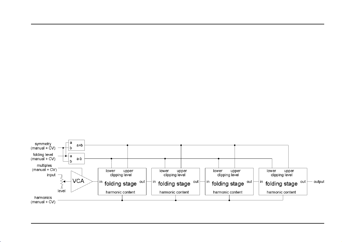
2. Basic principles
The signal is processed by a standard linear VCA and 4
so-called wave folding stages. The amplification of the
VCA is identical with the Multiples parameter. This is the
working principle of the folding stages: As soon as the
signal goes beyond the
folding level the signal is reflected resp. folded back. The
values for upper and lower folding level are derived from
the input parameters folding level and symmetry. Both
can be adjusted manually and controlled by an external
control voltage (CV).
stance between the upper and lower folding level, Fol-
ding Symmetry
zero line. The internal upper and lower folding level are
calculated by adding resp. subtracting the voltages for
Folding Level and Folding Symmetry (refer to fig. 3).
The working principle of one stage by means of a
triangle signal is shown in fig. 1. The upper picture
shows the incoming signal. The areas to be reflected are
filled black. The lower picture shows the output signal of
the stage. In this example the symmetry is slightly positive and the reflected areas are not symmetrical.
Fig. 2 shows the folding function of three stages. The
amplification (i.e. the
for the succeeding pictures to see the effect of increasing Multiples. Stage 4 is not shown because of clearness.
the position of both levels relating to the
Folding Level
Multiples
resp. below the
upper
determines the di-
parameter) is increased
lower
doepfer
Fig 1: Folding function for one stage
Fig 2: Folding function for three stages
2
Page 3
doepfer
System A - 100
Waveform Multiplier
A-137
As the amplification resp. the
creases even the peaks of the folded signal reach the
folding levels of the succeeding stage and the signal is
folded once again as shown in fig. 2. As the module
contains 4 folding stages up to 8 foldings are possible (4
at the upper and 4 at the lower clipping level). Consequently the maximum multiplication factor is 9 (8+1). If a
second A-137 module is added even more multiplications are possible.
The Harmonics parameter sharpens the waveform slo-
pes and adds some overshoot at the edges - a little bit
like the resonance resp. emphasis function of a filter.
Internally the harmonics feature is realized by an additional VCA for each folding stage.
Multiples
parameter in-
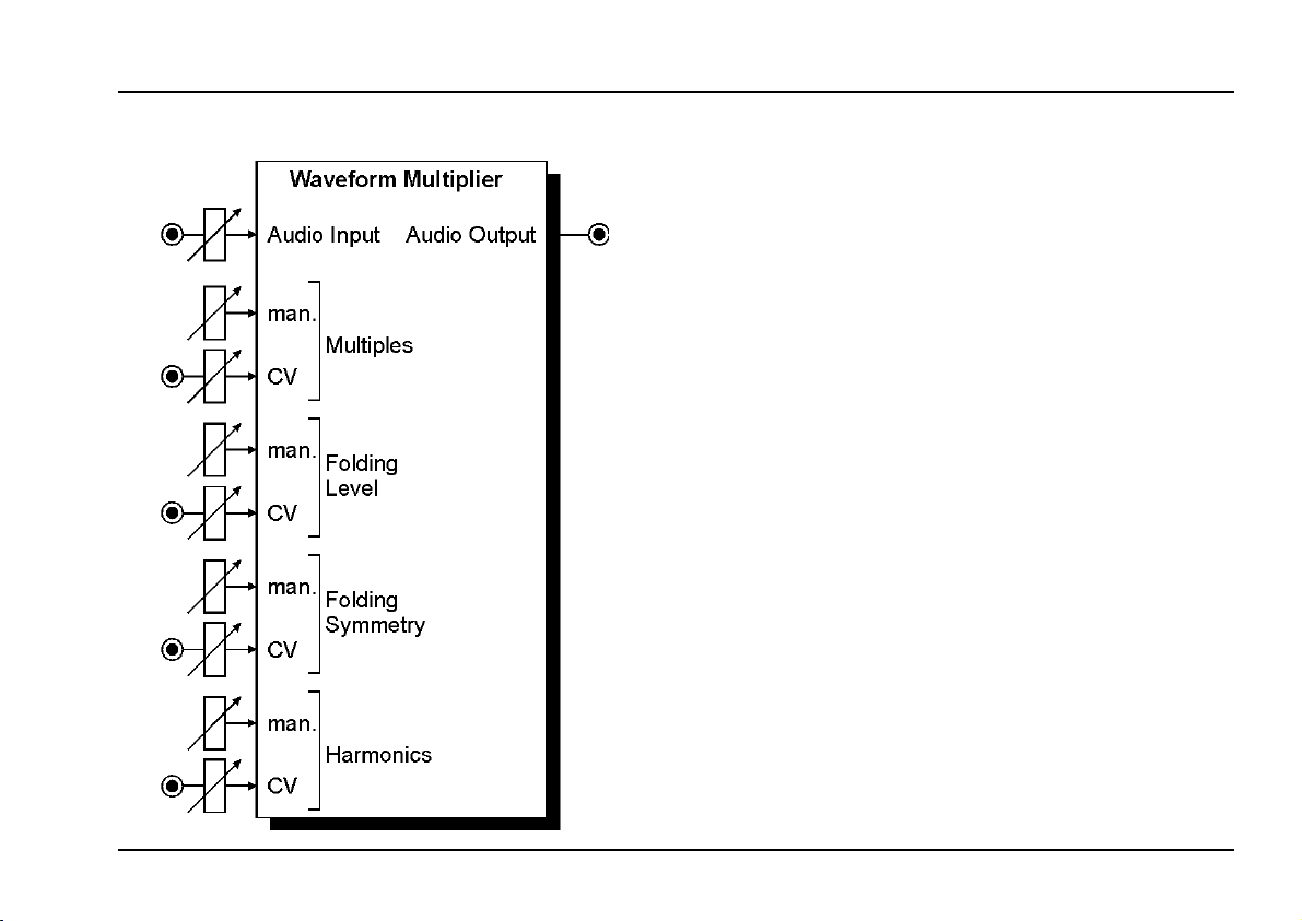
Fig 3 shows the complete schematics of the A-137
module. For each of the four parameters
Folding Level, Symmetry and Harmonics a manual control and an external control voltage input with attenuator
is available.
The external control of each parameter can be realized
with the usual modulation resp. CV sources: LFO,
ADSR, random voltage, MIDI-to-CV, Theremin, ribbon
controller, joy stick, foot controller and so on. Of course
simultaneous control of several parameters with different CV sources is possible (e.g. Multiples controlled by
and ADSR and
As the signals within the A-137 are fully DC coupled the
module can be used to process control voltages too.
Harmonics
by a LFO).
Multiples,
Fig. 3: Overall view
3
Page 4
A-137
Waveform Multiplier
System A - 100
doepfer
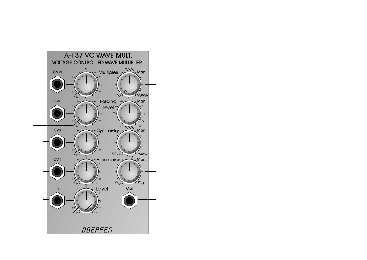
3. Overview
!
1a
"
2a
§
3a
4a
%
5
Controls:
1a CV Multiples: Attenuator for CV input !
1b Man. Multiples: Manual Multiples control
2a CV Folding Level: Attenuator for CV input "
2b Man. Folding Level: Manual
b
1
3a CV Symmetry: Attenuator for CV input §
3b Man. Symmetry: Manual Symmetry control
4a CV Harmonics: Attenuator for CV input $
b
2
4b Harmonics Man.: Manual Harmonics control
5 Level: Input level control
b
3
Folding Level
Inputs / Outputs:
! CVM: CV input
b
4
" CVF: CV input Folding Level
§ CVS: CV input
$ CVH: CV input Harmonics
&
% In: (Audio) input
& Out: (Audio) output
Multiples
Symmetry
control
4
Page 5

doepfer
System A - 100
Waveform Multiplier
A-137
4. Controls
1a CVM (knob) / ! CVM (socket)
1b Manual Multiples (knob)
This group of elements is responsible for the Multiples
parameter, i.e. the number of waveform multiplications
within one period (range 1...9).
2a CVF (knob) / " CVF (socket)
2b Manual Folding Level (knob)
This group of elements is responsible for the Folding
Level parameter, i.e. the distance between upper and
lower folding level.
3a CVS (knob) / § CVS (socket)
3b Manual Symmetry (knob)
This group of elements is responsible for the Symmetry
parameter, i.e. the asymmetrical shift of upper and lower
folding level relating to the zero level.
4a CVH (knob) / $ CVH (socket)
4b Manual Harmonics (knob)
This group of elements is responsible for the Harmonics
parameter, i.e. the sharpening of the waveform slopes
and the addition of overshoot at the edges similar to
resonance resp. emphasis function of a filter.
The following is valid for each of the 4 parameter groups:
Each parameter has available a manual control knob
(1b/2b/3b/4b) and an external control voltage input
(!/"/§/$). Each external CV input is equipped with an
attenuator (1a/2a/3a/4a) that allows to adjust the effect
of the external CV to the parameter in question.
The required control voltage difference at the sockets !
to $ is about 5V to reach all available settings, i.e. about
0...+5V with all attenuators set to it's maximum and all
manual controls to it's minimum positions.
5 Level (knob) / % In (socket)
This is the audio input of the module (e.g. triangle output
from a VCO) and the corresponding level control. Control 5 has the same effect as the Multiples parameter as
it is connected in series with the VCA that controls the
Multiples.
Level control 5 is adjusted so that the maximum effect
is obtained while passing through the complete Multiples
range (e.g. by turning knob 5 from fully counterclockwise to fully clockwise). If the input level is too small not
all waveform multiples will be reached. If the level is too
high the maximum waveform multiples are reached
even for middle positions of control 5 and the output
signal only distorts for higher settings of control 5. But
this may be a desired behaviour so that the level control
can be set intentionally to higher values.
5
Page 6

A-137
Waveform Multiplier
System A - 100
doepfer
& Out (socket)
This is the audio output of the module. The output signal
can be processed by other A-100 modules like filters,
VCAs, phaser, reverb or a second A-137.
5. User Examples
not yet ready
6
 Loading...