

Page 1

doepfer
Input
Ext. Level
Ext. Level
Output
A-136
DIS
A
+ L
- L
+ A
- A
System A - 100
1. Introduction
Module A-136 is a distortion and waveshaping mo-
dule with extensive control possibilities. Different settings of 5 distortion/waveshaping parameters enable a
lot of very complex and extreme waveform modifications.
The incoming audio or cv signal is divided into 3
sections: original, positive and negative component.
For the positive and negative component, clipping
levels (L) are defined. Only voltages beyond this level
effect the output signal. For each of the three sections
the positive or negative amplification (A) can be adjusted.
External control voltages can be used to alter both
clipping levels so that dynamic waveform changes are
possible.
The range of modification goes from simple soft or hard
clipping to completely altered waveforms where the
original signal is no longer recognizable.
Distortion / Waveshaper
A-136
Typical applications are audio distortion, and waveform
modification for audio signals as well as for control
voltages (LFO, ADSR, random etc.).
1
Page 2
A-136
Distortion / Waveshaper
System A - 100
doepfer
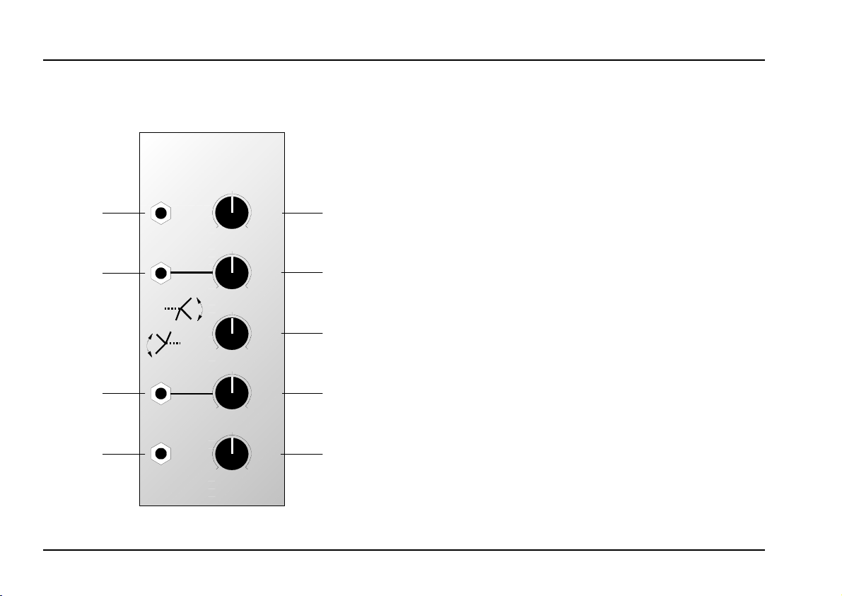
2. DIS - Overview
A-136
Distortion / Waveshaper
Input
Ext. Level
+L
+A
A
-L
-A
Ext. Level
Output
Controls:
A : Amplification control for original signal
1
DIS
+ A
10
0
+ L
10
0
A
10
0
- L
10
0
- A
10
0
➃
➁
➀
➂
➄
2 + L : Clipping control for positive signal compo-
nent
- L : Clipping control for negative signal com-
3
ponent
+ A : Amplification control for positive signal
4
component (above the positive clipping
level)
- A : Amplification control for negative signal
5
component (below the negative clipping
level)
In / Outputs:
Input : Signal input
!
" Ext. Level : ext. CV input for positive clipping level
Ext. Level
§
$ Output : Signal output
: ext. CV input for negative clipping le-
vel
2
Page 3

doepfer
System A - 100
Distortion / Waveshaper
A-136
3. Controls
1 A
Control 1 defines the amplification A of the original
signal. The range of the amplification factor is about
-4...+4. This means that one can obtain actual
amplification (range +1...+4), or attenuation (range
0...+1) or even inversion of the original signal (range
-4...0). The table below shows the approximate
assignment of some control settings and the
corresponding amplification factors:
Control
setting
3,5 about -1
6,5 about 1
10 about 4
Tab. 1: How control settings affect amplification
Amplification
factor
0 about -4
5 about 0
factors
Explanation
maximum negative amplification
same amplitude as input signal but
inverted
suppression of input signal
same amplitude as input signal
maximum positive amplification
2 + L • 3 - L
Controls 2 and 3 adjust the positive (+L) and
negative (-L) clipping levels respectively.
In the positive signal section only signal voltages
above the positive clipping level +L are affected by the
amplification control +A.
In the negative signal section only signal voltages
below the negative clipping level -L are affected by the
amplification control -A.
+ L
0
- L
Fig. 1: how the clipping levels work (input signal =
triangle)
3
Page 4

A-136
Distortion / Waveshaper
System A - 100
doepfer
H When an external control voltage is patched
to the normalled socket " (or § respectively)
control +L (or -L respectively) has no
function. In this case the clipping level is
determined only by the external control
voltage. This feature enables the dynamic
change of clipping levels by external control
voltage sources.
4 + A • 5 - A
With controls 4 and 5 respectively, the amplification
factors of the
the signal past the corresponding clipping level
thresholds are adjusted. The assignment of control
positions to amplification factors is the same as for the
original amplification control A (refer to tab. 1).
positive (+A) and negative (-A) parts of
4. In / Outputs
! Input
Socket ! is the
Ext. Level • § Ext. Level
"
If you want to control one or both of the clipping levels
from external control voltage sources (e.g. LFO,
ADSR, Random, Theremin, Sequencer, MIDI, and so
on) the normalled sockets " and § are used.
The clipping control +L (or -L respectively) sets the
clipping level unless an external control voltage is
patched into the Ext.Level
respectively). Please note that the positive (+A) section
of the A-136 takes effect only if the incoming signal
voltage is temporarily higher than the positive clipping
voltage. For the negative section the same applies: the
negative (-A) section of the A-136 takes effect only if
the incoming signal voltage is temporarily less than the
negative clipping voltage. If unsuitable external control
voltages are applied the A-136 may not work properly.
signal input
of the A-136.
socket (or
"
"
" "
§
$ Output
Socket $ is the A-136 output.
4
Page 5

doepfer
System A - 100
Distortion / Waveshaper
A-136
5. User Examples
Different settings of the 5 parameters enable a lot of
very complex and extreme waveform
modifications
simple soft or hard clipping to completely altered
waveforms where the original signal is no longer
recognizable. The sketch below shows a few examples
when a triangle signal is used as input.
An oscilloscope would be a good tool to see and
understand the waveform modifications resulting from
different parameter settings.
. The range of modifications varies from
Typical applications of module A-136 are:
• Audio distortion (especially interesting in
combination with filters), whereby the features of
the A-136 far exceed those of conventional
distortion or fuzz boxes
Waveform modifications for control signals (e.g.
•
new control waveforms derived from LFO, ADSR,
Random and so on)
Fig. 2: Examples for new waveforms derived from a triangle input with different parameter settings
5
Page 6

A-136
Distortion / Waveshaper
System A - 100
6. Patch-Sheet
The following diagrams of the module can help
you recall your own Patches. They’re designed so
that a complete 19” rack of modules will fit onto an
A4 sheet of paper.
Photocopy this page, and cut out the pictures of
this and your other modules. You can then stick
them onto another piece of paper, and create a
diagram of your own system.
Make multiple copies of your composite diagram,
and use them for remembering good patches and
set-ups.
P • Draw in patchleads with colored
pens.
• Draw or write control settings in the
little white circles.
A-136
Distortion / Waveshaper
Input
0
Ext. Level
+L
-A
Ext. Level
Output
0
+A
A
-L
0
0
0
DIS
10
10
10
10
10
+ A
+ L
A
- L
- A
A-136
Distortion / Waveshaper
Input
0
Ext. Level
+L
-A
Ext. Level
Output
0
+A
A
-L
0
0
0
DIS
10
10
10
10
10
+ A
+ L
A
- L
- A
doepfer
A-136
Distortion / Waveshaper
Input
0
Ext. Level
+L
-A
Ext. Level
Output
0
+A
A
-L
0
0
0
DIS
+ A
10
+ L
10
A
10
- L
10
- A
10
6
 Loading...