

Page 1
doepfer
System A - 100
1. Introduction
VC-Mixer
A-135
CV 1
CV 2
CV 3
CV 4
ext. CV
1
VC-Mixer
Gain 1
2
Gain 2
3
Gain 3
4
Gain 4
A-135
Audio In
Audio Out
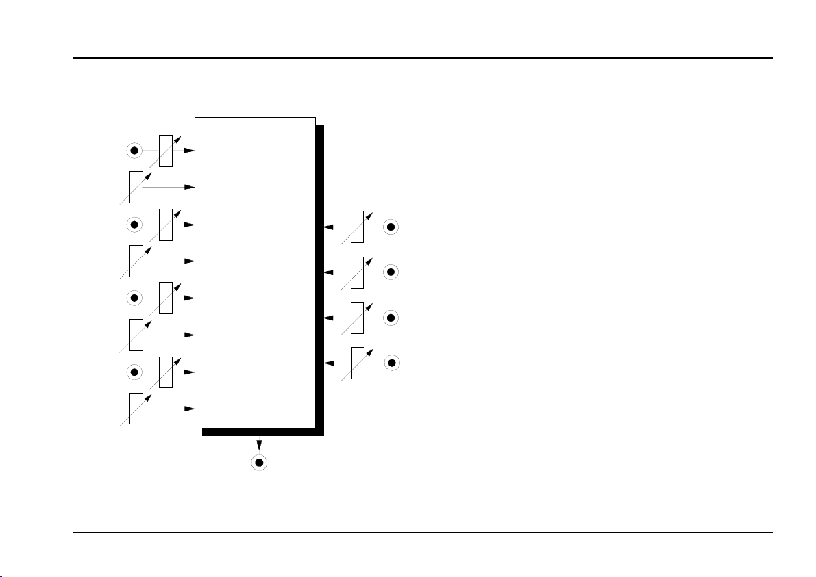
Module A-135 (VC-Mixer) is a four-channel voltage
controlled mixer
, which is used to mix audio signals
with four independent voltage controlled levels.
The module consists of 4 linear voltage controlled
Audio In 1
1
Audio In 2
2
Audio In 3
3
Audio In 4
4
amplifiers (VCAs) mixed to one common output. High
quality integrated VCAs (CEM3381) are used in the
circuit.
Each VCA has the following:
• Audio input with attenuator
• Control voltage input with attenuator
• Gain control (amplification offset).
1
Page 2
A-135
VC-Mixer
System A - 100
doepfer
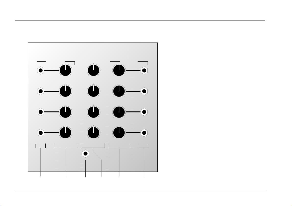
2. VC-Mix - Overview
A-135 VCMIX
VOLTAGE CONTROLLED MIXER
Audi o In ext. CVGain
10
0
10
0
10
0
10
0
Audio Out
Controls:
Audio In : Attenuator for audio si-
1
gnal at input !
2
1
10
0
10
0
2
10
0
10
0
3 ext. CV : Attenuator for control
In / Outputs:
! Audio In : Audio input
3
10
0
10
0
"
§ CV 2 : Control voltage input
4
10
0
10
0
: Control for amplification
Gain
offset
voltage at input
Audio Out
: Audio output (mixed out-
put of the four VCAs)
§
➀
➁
➂
2
Page 3

doepfer
System A - 100
VC-Mixer
A-135
3. Controls
1 Audio In
The four attenuators 1 control the levels of the audio
inputs. Adjust these controls to the desired input
levels of the audio signals
these controls serve to compensate for different audio
levels in the original signals so that the same control
voltage results in approximately the same audio level
at the output.
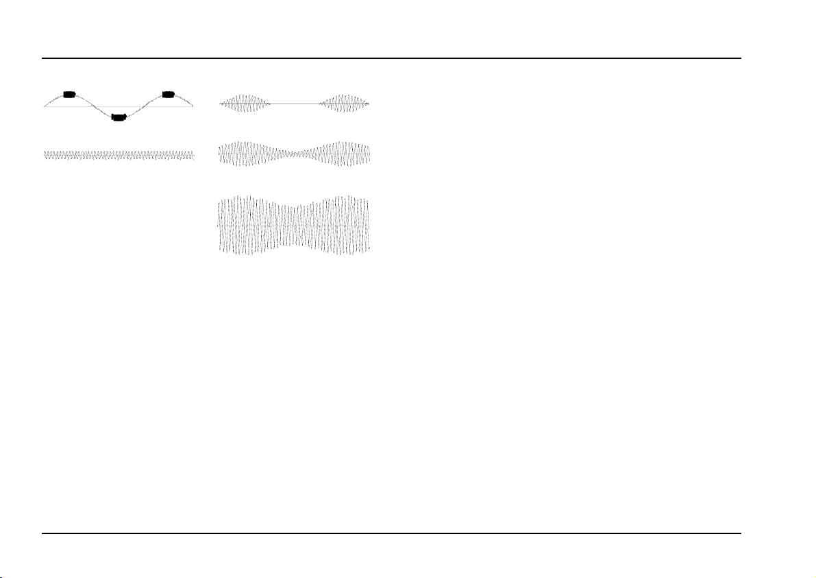
2 Gain
The gain control adjusts the amplification offset
(overall gain) for the VCA in question.
Position "0" corresponds to no amplification offset.
This means that the channel in question contributes
no signal to the output - provided that no positive
control voltage is applied to the external control voltage input.
Turning up the gain control increases the amplification proportional to the gain control setting - even if no
voltage is applied to the external control voltage input.
With the gain control, amplification response is shifted
up into the positive range (see Fig. 1).
at the inputs !. Basically
The VCA’s used in the
linear control response. The amplification is in direct
linear proportion to the control voltage input.
Fig. 1: Effect of gain control on VCA response
H For pure
an ADSR) the gain control is normally set to 0.
For bipolar control voltages (i.e. positive and
negative components, e.g. from LFO or random) the gain control is normally set to a
value larger than 0 so that the negative part of
the control signal is able to have an effect as
well (see. Fig.2).
positive control voltages
(CEM3381) have a
A-135
(e.g. from
3
Page 4
A-135
VC-Mixer
System A - 100
doepfer
CV
Input
Fig. 2: Resulting amplification with bipolar control
voltage (CV) and different gain settings
ext. CV
3
This attenuator affects the level of voltage control at
socket ". It controls the amount of effect the CV has
on amplification.
Output ( Gain = 0 )
Output ( Gain > 0 )
Output ( Gain >> 0 )
4. In / Outputs
! Audio In
The signals you wish to amplify are input through the
four audio inputs !.
Audio Out
"
The output signal " is the sum of the four audio inputs
amplified by the four VCAs.
§ ext. CV
Sockets § are the control voltage inputs.
The effective control voltage range of each VCA goes
from 0 V (no amplification) to about +5 V (maximum
amplification). The effective control voltage is the sum
of the voltages coming from the gain control 2 (about
0...+5V), and the external control voltage § that may
be attentuated with control 3.
4
Page 5

doepfer
System A - 100
VC-Mixer
A-135
5. User examples
Module A-135 enables voltage controlled mixing of
up to 4 audio sources
ges.
The control voltages can be generated by any voltage
source or even by audio sources for special effects
(similar to ring modulator or FM sound). Here are
some examples of possible control voltage sources:
• LFOs (A-145, A-146, A-147)
• ADSRs (A-140, A-141, A-142, A-170)
• Random (A-118, A-148)
• Shepard-Generator (A-191)
• external audio signals in combination with an enve-
lope follower (A-119)
Analog sequencer (A-155, MAQ16/3)
•
Theremins (A-178)
•
Light controls (A-179)
•
• Foot controls (A-177)
It is also possible to use MIDI-controlled voltages in
combination with a MIDI-CV-Interface (A-190, A-191,
MCV4, MCV24):
with 4 different control volta-
Pitch CV
•
After touch
•
• Pitch bend
• Modulation
• Volume
• any MIDI Controller
For example, the combination of A-135 and A-191 can
create a simple MIDI-controlled mixer.
One special application is using the Morphing Con-
troller A-144 to generate the control voltages for the
A-135. This enables cross-fading (morphing) of 4 audio sources with only one controlling voltage. This
single controlling voltage defines the fading or morphing position. For details refer to the A-144 user’s
guide.
5
Page 6

A-135
VC-Mixer
6. Patch-Sheet
System A - 100
doepfer
The following diagrams of the module can help you
recall your own Patches. They’re designed so that a
complete 19” rack of modules will fit onto an A4 sheet
of paper.
Photocopy this page, and cut out the pictures of this
and your other modules. You can then stick them onto
another piece of paper, and create a diagram of your
own system.
Make multiple copies of your composite diagram, and
use them for remembering good patches and set-ups.
P • Draw in patchleads with colored pens.
• Draw or write control settings in the little
white circles.
A-135 VCMIX
VOLT AGE CONT ROLLE D MIXE R
Audi o In ext. CVGain
10
10
10
10
Audio Out
0
0
0
0
0
0
0
0
10
10
10
10
10
0
10
0
10
0
10
0
1
2
3
4
6
 Loading...