

Page 1
doepfer
CV 2
A-134
VC Panning Module
CV 2
System A - 100
Voltage Controlled Panning
A-134
1. Introduction
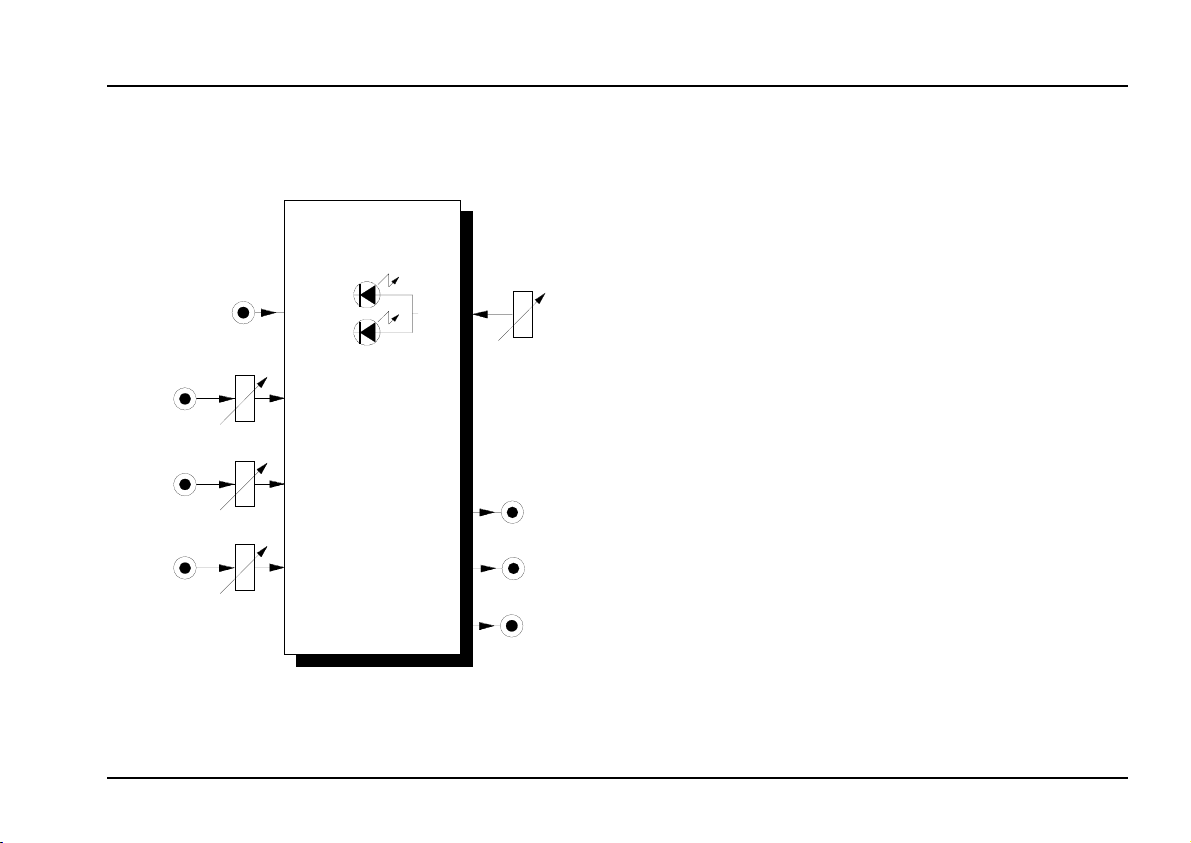
Module A-134 (PAN) is designed to provide voltagecontrolled panning
It can equally well pan between inputs (with two inputs going to one output) and
PanCV 1
input going to two outputs.
As well as the manual mode, panning can also be
voltage-controlled. Two CV inputs (one with an attenuator control are included for that purpose.
for audio signals.
between outputs -
one
Lev 1
Lev 2
Audio In 1
Audio In 2
Left
Out
Mix
Out
Right
Out
Two
pening to the signals.
To set the incoming audio signals at the right level,
both Audio Inputs have
give a visual indication of what’s hap-
LEDs
attenuators
.
1
Page 2
A-134
Voltage Controlled Panning
System A - 100
doepfer
2. PAN - Overview
A-134
VC Panning Module
CV 1
CV 2
Audio In 1
Audio In 2
Left
Output
Mix
Output
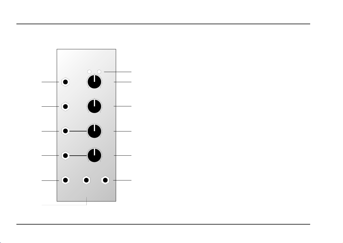
Controls and indicators:
LEDs : status indicators for audio output
PAN
Pan
10
0
CV 2
10
0
Lev 1
10
0
Lev 2
10
0
Right
Output
➀
➁
➂
➃
➄
1
2 Pan : manual panning control
CV 2 : attenuator for the CV at input
3
4 Lev 1 : attenuator for audio signal at input §
Lev 2 : attenuator for audio signal at input
5
"
In- / Outputs:
: control voltage input
CV 1
!
CV 2 : ditto, with attenuator
"
Audio In 1
§
Audio In 2
$
Left Output
%
Mix Output
&
Right Output
/
: input for first audio signal
: input for second audio signal - a swit-
ched socket, so that if nothing is
connected to it, it is automatically linked to socket
: left audio output
: mix output
: right audio output
§
§
$
2
Page 3
doepfer
System A - 100
Voltage Controlled Panning
A-134
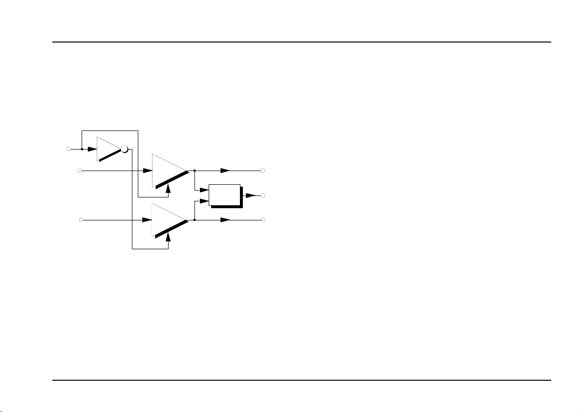
3. Basic layout
The A-134 provides both manual and voltagecontrolled panning. It basically contains two matched
linear VCAs like the A-130, and a mixer (see fig. 1).
CV
Audi o
In 1
Audio
In 2
Fig. 1: basic construction
In input mixing mode, the signals from the two audio
inputs are mixed and sent to Mix Output &. By using
the two pan controls 2 and/or any control voltages
connected, you can control the
the two input signals in the mix. The matched
VCAs, with one signal inverted, enable the relative levels of the signals to be controlled automatically.
Inv
VCA 1
VCA 2
Mix
Right
relative amounts of
Left
Out
Mix
Out
Out
In
output panning mode,
the signal present at audio
input 1 (§) is sent to the left (%) and right (/) audio
outputs at levels determined by the pan control 2 and/
or the control voltage/s input to the module. In this
way, you can control the
position of the signal in the
stereo soundstage.
A typical application is to make a signal move regularly about in the stereo soundstage. To do this, a
slow LFO is connected to CV input ! and/or " on the
A-134.
4. Controls and indicators
1 LEDs
The two LEDs 1 indicate the level of signals going
to outputs %, & and /; how they do this depends on
the mixing / panning mode:
Input mixing mode:
In this mode, the left LED refers to audio input §, and
the right to audio input $. The LEDs show the relative
signal levels from each of the inputs being sent to
Mix output &. Table 1 shows the result of differing
control voltages or positioning of the Pan control.
3
Page 4

A-134
Voltage Controlled Panning
System A - 100
doepfer
Pan LEDs Mix Output
0
5
10
Table 1: Input mixing mode
Output panning mode:
In this mode, the left LED monitors the left audio output %, the right LED the right audio output /. The
LEDs indicate the relative position in the stereo
soundstage produced by the two audio outputs. Table 2 shows the result of differing control voltages or
positioning of the Pan control.
Pan LEDs Left Output Right Output
0100 %0 %
5 50 % 50 %
10 0 % 100 %
Just the signal from Audio In 1
Equal amounts of signal from
Audio In 1 and Audio In 2
Just the signal from Audio In 2
2 Pan
Control 2 is used to control the relative signal levels
at outputs %, & and /. In
control the relative amounts of each of the input signal present at the Mix output; in output panning
this determines the
mode
soundstage.
input mixing mode,
position in the stereo
you
3 CV 2
Attenuator 3 is used to adjust the level of control
voltage
present at CV input " .
4 Lev 1 • 5 Lev 2
The level of the audio signals at inputs § and $ is
controlled by attenuators 4 and 5 .
Table 2: Output panning mode
4
Page 5

doepfer
System A - 100
Voltage Controlled Panning
A-134
5. In- / Outputs
! CV 1 • " CV 2
Inputs ! and/or " are for the control voltages to be
used for voltage-controlled panning.
H The actual amount of panning is governed by
the sum of the voltages produced by the pan
control 2 and CV control 3.
Audio In 1 • $ Audio In 2
§
Sockets § and $ are the module’s audio inputs. This
is where one or two audio signals are input, with their
level controlled by attenuators 4 and 5.
H
% Left Output • / Right Output
Sockets % and & are the left and right audio out-
puts
& Mix Output
The Mix Output & is used in input mixing mode.
Audio input $ is a switched (normalled)
socket. If there’s nothing connected to it, it’s
automatically linked with input §.
. These are used in output panning mode.
6. User examples
There are a whole load of possibilities for using Module A-134, principally because any signal you think of
can be used as a control voltage:
•
LFO
cyclical changes in output panning;
depending on the frequency, waveform and amplitude of the LFO, the signal moves from left to right
and vice versa.
ADSR, VC-ADSR, VCD
•
panning depending on the envelope’s voltage.
Random-CV
•
random panning;
fig. 2 shows a patch in which the position of the
sound in the stereo soundstage changes with each
new note played. The patch in fig. 3 produces an
output signal which alter the degree of rasp in the
osund with each new key-stroke or sequenced
note. (See also the user examples for the A-126)
Foot-Controller
•
Foot-controlled panning.
Theremin
•
Panning uy using hand-movements (see fig. 4) relative to the theremin’s antenna.
5
Page 6

A-134
Voltage Controlled Panning
System A - 100
doepfer
•
Sequencer
Panning controlled by voltages put out by a sequencer such as the A-155.
In the patch in fig. 5, the control voltages are
produced by the lower row of the A-155, so that
as the sequence runs, each note is positioned
at a different place in the stereo soundstage.
(Lessening the abrupt changes between voltages can be achieved by using Post Out 2 on the
A-155.)
MIDI Interface
•
By patching in a MIDI interface (such as the A190 or A-191) you can use virtually any MIDI
Controller message to control panning (for instance the mixing two signals using Aftertouch).
You can also use the pitch information generated by the MIDI interface to control any aspect
you want - for instance voltage-controlled panning using pitch data, perhaps making lower notes appear more on the left of the soundstage,
and higher notes on the right.
CV
Gate
VCO
VCF
VCA
ADSR
Audio
In 1
Left
Out
PAN
Right
Out
A-1 18
Random
Out
CV In
A-148
Trig. In
Fig. 2: Random position in the stereo soundstage
each time a key is pressed.
6
Page 7

doepfer
System A - 100
Voltage Controlled Panning
A-134
Audio
In 1
AudioSignal
VCFS
CV In
Colored
A-118
Up
Random
Out
Audio
In 2
A-1 48
Trig. In
Gate
: Randomly making a sound more harsh or ra-
Fig. 3
sping each time a note is pressed.
PAN
CV In
Mix
Out
Left
Out
Right
Out
Audio
Audio
In 1
PAN
CV In
CV
A-178
Audio
CV
In 1
Audio
In 2
PAN
CV In
Mix
Out
Audio 1
Audio 2
A-178
Fig. 4: Panning using the theremin module.
7
Page 8

A-134
Voltage Controlled Panning
Clock
System A - 100
doepfer
A-155
1 2 3 4 5 6 7 8
Trig. 1
Glide Crt l. 1
Gate
Pre Out 1
Post Out 2
Fig. 5: Output panning using a sequencer.
VCO
ADSR
VCF
VCA
:
#
Left
Out
#
#
Audio
In 1
PAN
Right
CV In
Out
8
Page 9

doepfer
System A - 100
Voltage Controlled Panning
A-134
9
Page 10

A-134
Voltage Controlled Panning
6. Patch-Sheet
System A - 100
doepfer
The following diagrams of the module can help
you recall your own
Patches
. They’re designed so
that a complete 19” rack of modules will fit onto an
A4 sheet of paper.
Photocopy this page, and cut out the pictures of
this and your other modules. You can then stick
them onto another piece of paper, and create a
diagram of your own system.
Make multiple copies of your composite diagram,
and use them for remembering good patches and
set-ups.
P • Draw in patchleads with colored
pens.
• Draw or write control settings in the
little white circles.
A-134
VC Panning M odule
CV 1
0
CV 2
0
Audio In 1
0
Audio In 2
0
Left
Output
Mix
Output
PAN
Pan
10
CV 2
10
Lev 1
10
Lev 2
10
Right
Output
A-134
VC Panning Module
CV 1
0
CV 2
0
Audio In 1
0
Audio In 2
0
Left
Output
Mix
Output
PAN
Pan
10
CV 2
10
Lev 1
10
Lev 2
10
Right
Output
A-134
VC Panning Module
CV 1
0
CV 2
0
Audio In 1
0
Audio In 2
0
Left
Output
Mix
Output
PAN
Pan
10
CV 2
10
Lev 1
10
Lev 2
10
Right
Output
10
 Loading...