

Page 1
doepfer
System A - 100
1. Introduction
Dual VC Polarizer
A-133
CV
CV
A-133
Dual VC Polarizer
CV
In
Out
CV
In
Out
Man.
Man.
Module A-133 (
voltage controlled amplifier that enables both positive and negative amplifications. Negative amplifica-
tion means in this context that the signal is
+
-
+
-
The main application of the module is the processing
of control voltages
audio signals can be processed with this module.
The amplification range is about -2.5....0....+2.5. Am-
plification can be adjusted manually (Man control) or
by an
external control voltage
The present
LEDs: one for positive and one for negative amplifications.
Dual VC Polarizer
e.g. ADSR or LFO. But even
,
amplification
.
is
) is a
special dual
displayed
inverted
with
.
two
1
Page 2
A-133
Dual VC Polarizer
System A - 100
doepfer
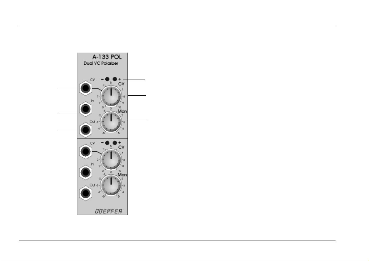
2. Overview
➊
➋
➌
➀
➁
➂
Controls and indicators:
LEDs : negative/positive amplification display
1
(not a signal display !)
: attenuator for the control voltage at
CV
2
input ! that controls the amplification
3 Man. : manual amplification control
In- / Outputs:
CV : control voltage input
!
" In : signal input
: signal output
Out
§
2
Page 3

doepfer
System A - 100
Dual VC Polarizer
A-133
3. Controls and Indicators
1 LEDs
The two LEDs
rizer in question (attention: in contrast to the LED
displays of other modules they do not show the signal
but the amplification factor !).
Tab. 1 shows the connection between LED display
and amplification. At maximum negative amplification
(about -2.5, signal inverted !) the left LED lights with
maximum brightness. At maximum positive amplification (about +2.5, signal not inverted!) the right LED
lights with maximum brightness. With amplification
about zero (i.e. no output signal) both LEDs are off.
indicate the amplification
2 CV
The attenuator 2 is used to adjust the effect of the
external control voltage
on the amplification.
3 Man.
This control is used to adjust the amplification manually. The range is about -2.5 to +2.5 (without external
control voltage). The middle position corresponds to
about zero amplification (but in any case the LEDs
should be used to find out the current amplification).
of the pola-
Man. LEDs a In Out
-5 -2,5
-2 -1
00
21
52.5
Tab. 1: Connection between manual control (Man.) ,
LED display, amplification (a) and effect on
the output signal
H
It is possible to obtain other amplification
ranges (e.g. -1 ...+1 or -5 ...+5). For this a
resistor has to be replaced. Please look at
the A-100 service manual or contact hardware@doepfer.de. We think that -2.5...+2.5
is a good compromise as higher amplificati-
3
Page 4

A-133
Dual VC Polarizer
System A - 100
doepfer
ons would cause clipping for all standard
A-100 signals (like LFOs, ADSRs or VCOs).
If the amplification is negative the signal is inverted
(see table above).
The effects of the manual control 3 and the external
control voltage ! with attenuator 2 are added up.
4. In- / Outputs
! CV
This jack socket is the control voltage input to control
the amplification by an external control signal.
" In
The signal to be amplified/inverted (control voltage or
audio) is fed into this
Out
§
Socket § is the signal output.
signal input socket
".
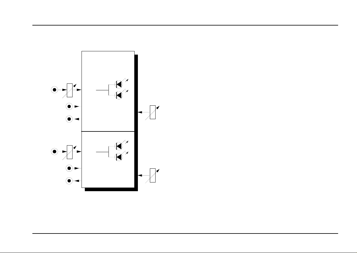
5. User examples
One application is the
For this two VCO outputs are connected to the signal
and the control input of the A-133 (see fig.1).
generation of new waveforms.
CV In
VCO A-133
In
: Generating new waveforms
Fig. 1
Same applies for
LFOs even ADSRs or other CV sources can be used.
LFO 1 A-133
LFO 2
Fig. 2: Control voltage modulation, arrows indicate
polarity changes
Additional examples:
voltage controlled feedback of filters (e.g. A-108),
•
phaser (A-101-3) or spring reverb (A-199)
polarity change of envelope signals (frequency CV
•
is used to control both filter frequency and polarizer
amplification simultaneously)
modulations
CV In
In
Out
(see fig. 2). Instead of
Out
000
4
 Loading...