

Page 1
doepfer
A-132
DUAL VCA
CV 1
System A - 100
1. Introduction
Module A-132 (Dual Low Cost VCA) contains two
voltage controlled amplifiers
most suited to regulating the level of control voltages
(ADSR amount, level of vibrato effect, etc.).
Dual Low Cost VCA A-132
, with a linear response
CV 2
Sig.
In
Sig.
Out
CV 1
CV 2
Sig.
In
Sig.
Out
In non-critical situations, though, its VCAs can be used
to control audio signals - see chapter 4, user examples.
Amplification is governed by the sum of the voltages
patched into the two CV inputs.
1
Page 2
A-132
Dual Low Cost VCA
System A - 100
doepfer
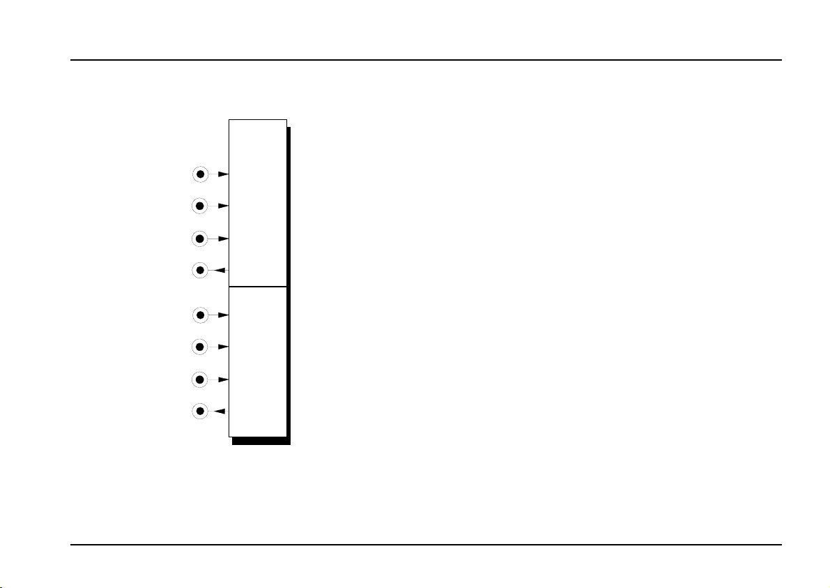
2. Dual Low Cost VCA - Overview
A-132
DUAL VCA
CV 1
CV 2
Sig.
In
Sig.
Out
CV 1
CV 2
Sig.
In
Sig.
Out
In / Outputs:
CV 1 : Input 1 for amplification CV
!
" CV 2 : Input 2 for amplification CV
Sig. In
§
Sig. Out : Amplifier output
$
: Amplifier input
2
Page 3

doepfer
System A - 100
Dual Low Cost VCA A-132
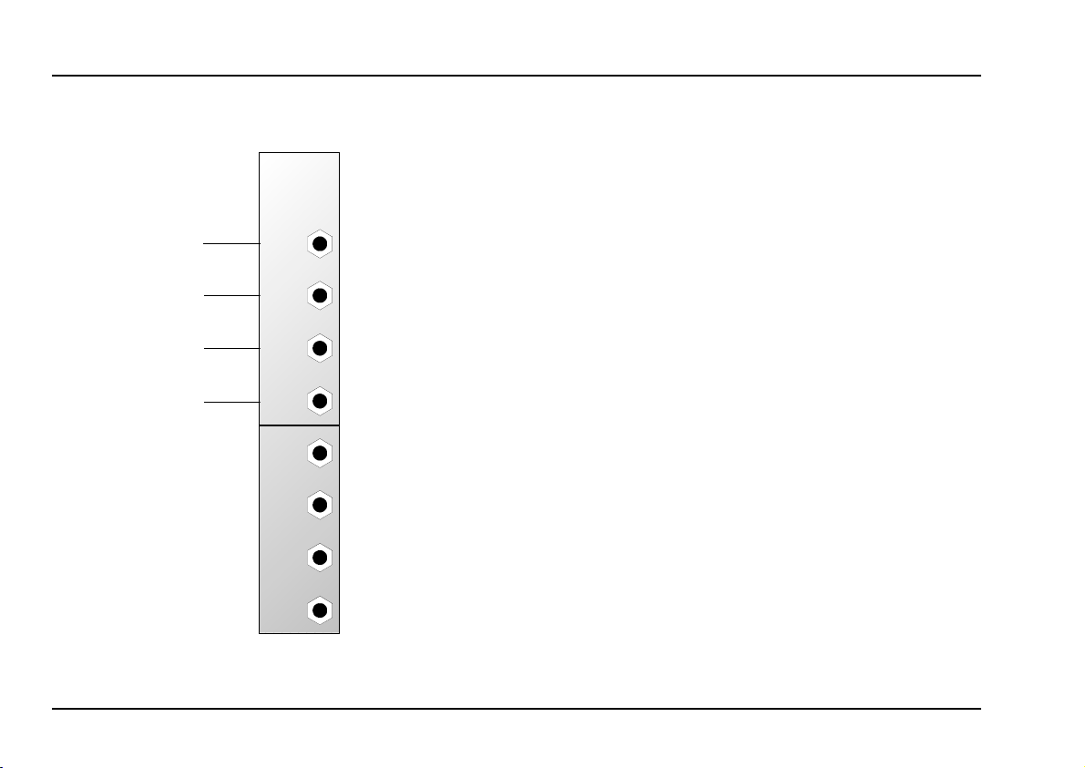
3. In / Outputs
! CV 1 • " CV 2
Sockets ! and " are the VCA’s
inputs. Whatever voltages are patched in here are
summed, and determine the amount of amplification
in the VCA (0 V: zero amplification; 5 V: maximum
amplification).
Sig. In
§
Patch the signal to be controlled by the VCA into input
socket §.
$ Sig. Out
The VCA output socket $ sends the signal out once
it’s been amplified by the sum of the control voltages
patched into the VCA.
control voltage
4. User examples
Control of modulation amount by AM
In Fig. 1 an A-132 is added to the patch to make the
amount of modulation voltage-controlled. Each of
the VCAs has the following function in this patch:
• VCA 1 : A-130, control of AM
• VCA 2 : A-131, control of total volume
VCA 3 : A-132, control of modulation amount
•
The control voltage for modulation amount (eg. from a
MIDI-CV interface) is patched in at point A.
VCO
LFO
VCA 3
lin.
A
VCA 1
lin.
CV
CV
VCA 2
log.
ADSR
Fig. 1: AM with voltage-controlled modulation amount
3
Page 4

A-132
Dual Low Cost VCA
System A - 100
doepfer
MIDI-controlled VCF or VCA envelope
amount
One important use of the A-132 is to control a VCF or
VCA envelope according to how much velocity CV a
MIDI-CV interface is putting out, as in Fig. 2.
VCF /
VCA
Gate
Velocity CV
Audio Signal
A-132
MIDI-
Interface
ADSR
Fig. 2: Controlling the level of a VCF or VCA enve-
lope by the velocity CV output from a MIDI
interface.
Audio signal amplitude control
For non-critical applications, the A-132 can also be
used for amplifying audio signals.
In the example in Fig. 3, an A-132 is patched in to
make the level of noise in an audio signal voltagecontrolled. The control voltage CV
come from the velocity output of a MIDI-CV interface;
or from an envelope, for a chiff at the start of each
note.
VCO
A-118
A-132
CV
N
Fig. 3: Audio signal amplitude control
could for instance
N
A-138
4
Page 5
doepfer
System A - 100
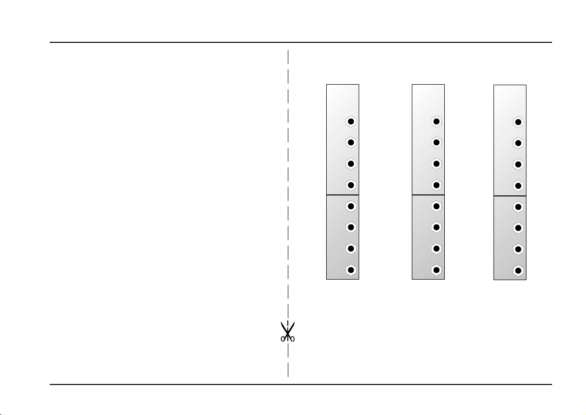
6. Patch-Sheet
The following diagrams of the module can help
you recall your own Patches. They’re designed so
that a complete 19” rack of modules will fit onto an
A4 sheet of paper.
A-132
DUAL VCA
CV 1
Dual Low Cost VCA A-132
A-132
DUAL VCA
CV 1
A-132
DUAL VCA
CV 1
Photocopy this page, and cut out the pictures of
this and your other modules. You can then stick
them onto another piece of paper, and create a
diagram of your own system.
Make multiple copies of your composite diagram,
and use them for remembering good patches and
set-ups.
P • Draw in patchleads with colored
pens.
CV 2
Sig.
In
Sig.
Out
CV 1
CV 2
Sig.
In
Sig.
Out
CV 2
Sig.
In
Sig.
Out
CV 1
CV 2
Sig.
In
Sig.
Out
CV 2
Sig.
In
Sig.
Out
CV 1
CV 2
Sig.
In
Sig.
Out
5
Page 6

A-132
Dual Low Cost VCA
System A - 100
doepfer
6
 Loading...