

Page 1
doepfer System A - 100 VCA A-130 / A-131
1. Introduction
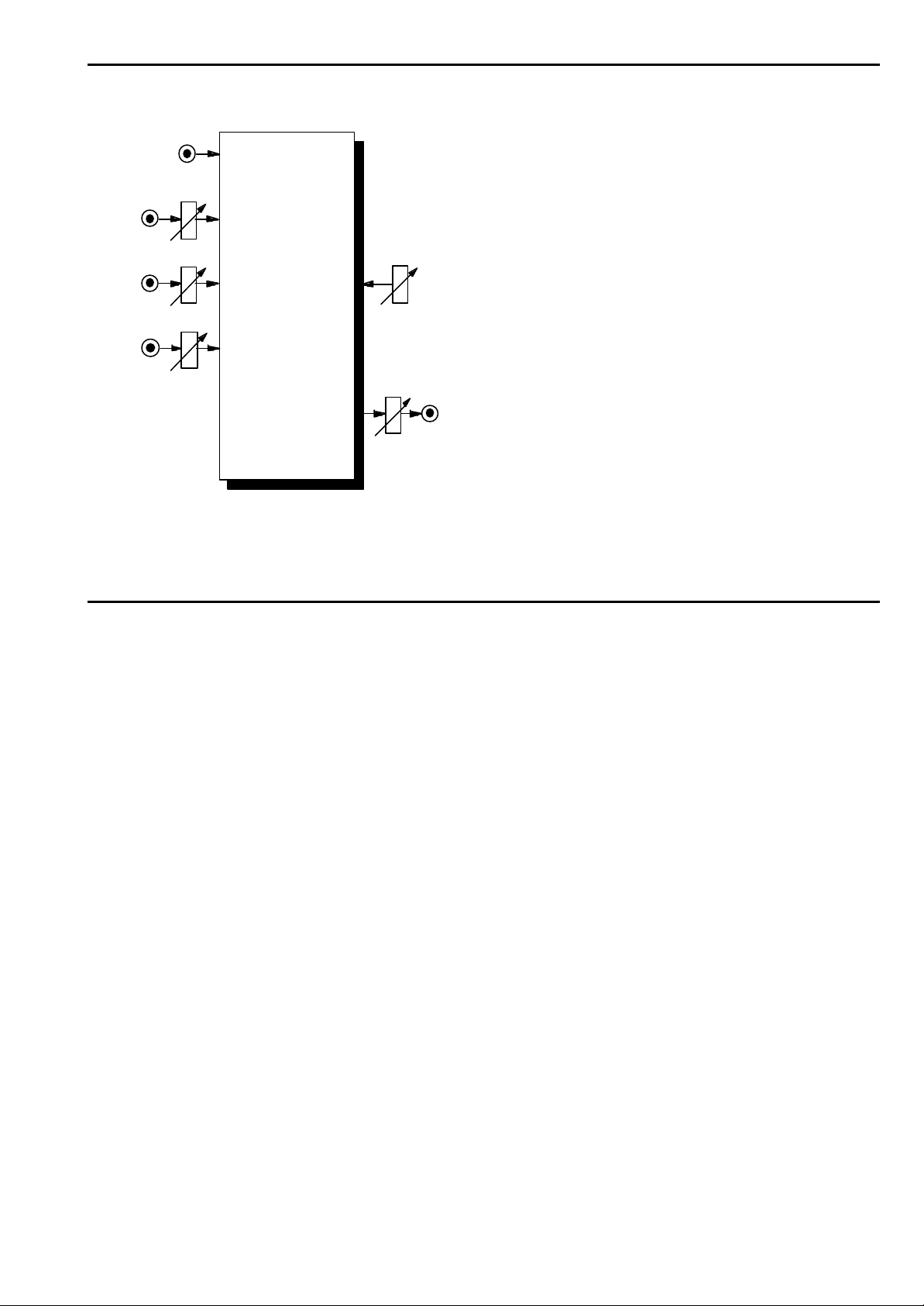
Modules A-130 (Linear VCA) and A-131 (Exp. VCA)
CV 1
A-130
provide voltage-controlled amplification.
CV 2
In 1
In 2
CV 2
A udio
In 1
Audio
In 2
V CA-LIN.
Gain
Audio Out
Out
H This section of the manual applies equally to
the A-130 and A-131, because apart from the
one difference of their response curves, they
are otherwise identical.
For audio signals, you would normally use the exponential VCA (A-131), and for control voltages, the linear
VCA (A-130). It doesn’t always have to be that way,
though.
The amount of amplification the VCAs provide is determined by the voltage at the CV input, and the position
of the gain control, which sets the overall gain in the
system.
The VCA has two audio inputs, each with an attenua-
tor. They are amplified by an amount determined by the
combination of the gain and the two CV controls.
1
Page 2
A-130 / A-131 VCA System A - 100 doepfer
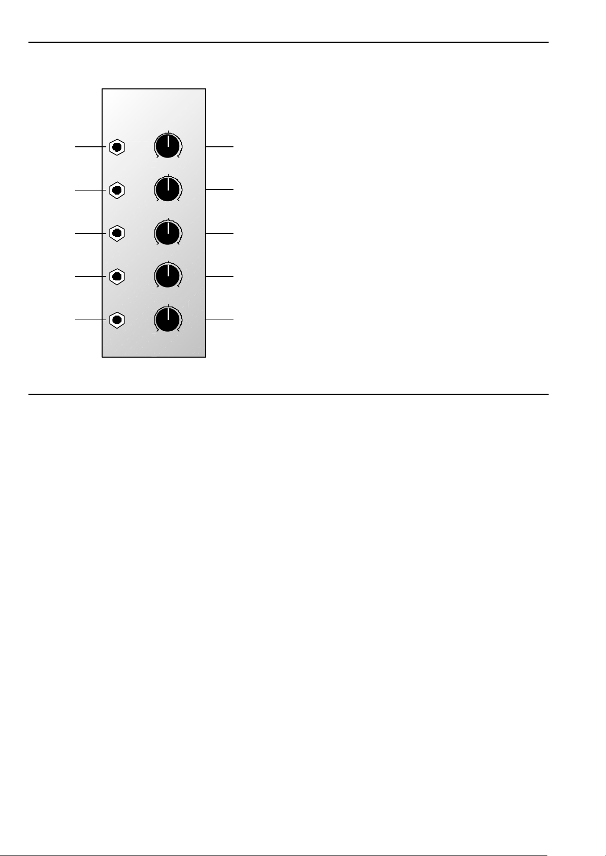
2. VCA - overview
A -130
CV 1
Ê
CV 2
Ë
Audio In 1
Ì
Audio In 2
Í
Audio Out
Î
VCA-LIN.
Gain
10
0
CV 2
0 10
In 1
10
0
In 2
10
0
Out
0 10
À
Á
Â
Ã
Ä
Controls:
1 Gain: Overall gain control
2 CV 2: CV attenuator for input "
3 IN 1: Attenuator for audio input §
4 IN 2: Attenuator for audio input $
5 Out: Attenuator for the output signal
In / Outputs:
! CV 1: Control voltage input
" CV 2: ditto, with attenuator
§ Audio In 1: Audio input
$ Audio In 2: ditto
% Audio Out: Audio output for the combined audio
signals input at § and $ and then
amplified by the VCA.
2
Page 3
doepfer System A - 100 VCA A-130 / A-131
3. Controls
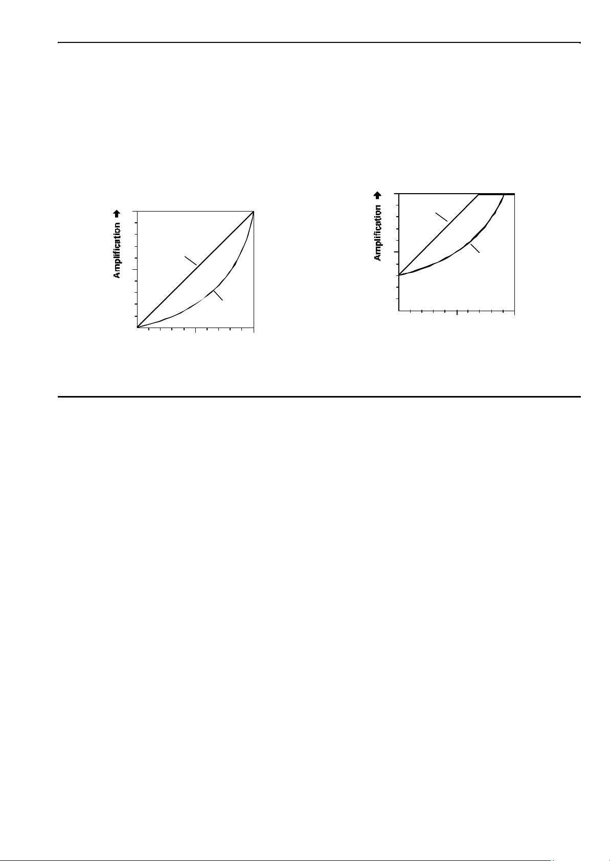
The A-130 has a linear response: the amplification is in
direct linear proportion to the control voltage input (see
Fig. 1).
The A-131 has an exponential (or logarithmic) response. That means that control voltage changes have
less effect at low levels of amplification than at high
levels, and makes the A-131 more sensitive and suitable for subtle changes at low levels (see Fig. 1).
10
lin.
5
e xp.
0
5 10
Control Voltage
èè
1 Gain
This controls the overall gain of the VCA.
At "0", with no control voltage present, there is no
amplification at all: no signal is present at the VCA’s
output. Once the gain control is turned up, amplification
occurs, even if there is no CV input present. The gain
control shifts the whole VCA response upwards (see
Fig. 2).
10
lin.
5
Ga in = 3
0
Control Voltage
e xp.
5 10
èè
Fig. 1: Response curves for the A-130 and A-131
Fig. 2: Effect of gain control on VCA response
3
Page 4

A-130 / A-131 VCA System A - 100 doepfer
H Note that if a control voltage is partially nega-
tive (for instance an LFO modulating the VCA)
you need to set the VCA gain above zero,
since otherwise the input signal is only amplified when the modulation CV is positive (see
Fig. 3).
Input
CV
Fig. 3: VCA output level at different gain settings.
Gain > 0
Output
Gain = 0
2 CV 2
This attenuator affects the level of voltage control at
socket ". It controls the amount of effect the CV has
on amplification.
3 IN 1 • 4 IN 2
Attenuators 3 and 4 control the level of the signals
input into the VCA.
H If the output signal distorts in an unwanted
way, turn down the input level, using control
3 and/or 4.
5 Out
This attenuator controls the total volume of the VCA’s
output.
4
Page 5

doepfer System A - 100 VCA A-130 / A-131
4. In / Outputs
! CV 1 • " CV 2
Sockets ! and " are control voltage inputs, whose
voltages are combined. The effective range of the VCA
goes from 0 V (no amplification) to +5 V (maximum
amplification).
§ Audio In 1 • $ Audio In 2
The signals you wish to amplify are input through audio
inputs § and/or $.
% Audio Out
The output signal here is the audio inputs amplified by
the VCA..
5. User examples
Typical voltage controlled amplification
A standard VCA patch is shown in Fig. 4. An ADSR
envelope produces a time-dependent amplification
curve, which can affect any sound source you choose.
The curve can be very quick (with a fast envelope) or it
can produce long, slow changes in the volume of a
sound.
CV 2
Audio
In 1
A-131
V C A-EX P.
Gain
Out
Audio Out
ADSR
CV 2
In 1
NOISE
Fig. 4: Time dependent amplification using an ADSR
5
Page 6

A-130 / A-131 VCA System A - 100 doepfer
Amplitude modulation
In Fig. 5, an LFO is modulating an A-130 linear VCA
(with Gain > 0), so that the amplification changes
cyclically with the LFO’s voltage. (Amplitude modu-
lation / AM.)
With an LFO frequency in the sub-audio range (1 Hz to
around 15 Hz) the result is Tremolo (see Fig. 5).
With a modulation frequency in the audio range, sidebands occur like those produced by FM (Frequency
Modulation), and interesting timbres emerge.
CV 2
Audio
In 1
A-130
VCA-LIN.
Gain
Audio Out
Ga in > 0
Out
LFO
VCO
CV 2
In 1
Modulation depth is adjusted with control 2.
Fig. 6 shows a way of voltage-controlling this modula-
tion depth using another VCA. In this example, the
VCAs have the following functions:
• VCA 1 (A-130): AM control
• VCA 2 (A-131): total volume control
• VCA 3 (A-130): modulation depth control
The voltage control input A to the modulation depth VCA
can come from an ADSR, MIDI controller, etc..
VCO
LFO
VCA 1
CV
VCA 3
CV
A
VCA 2
Fig. 5: VCA amplitude modulation with an LFO
6
Fig. 6: AM with voltage-controlled modulation depth
Page 7

doepfer System A - 100 VCA A-130 / A-131
Keyboard control of VCA (tracking)
You can use the CV output from a keyboard to modulate the VCA, and so have level of amplification de-
termined by the pitch of a note - what’s usually called keyboard tracking.
In the example in Fig. 7, high frequency notes are
amplified more than low frequency notes. Use control 1
on VCA 2 to vary the degree of keyboard tracking.
CV
VCO
Gate
VCA 1
ADSR
Fig. 7: Keyboard tracking - the higher the pitch, the
louder the output
VCA 2
CV1
mfp f
To produce the opposite effect (that is, inverse keyboard
tracking, where lower sounds are more amplified than
higher ones) patch a Voltage-Inverter A-175 in before
VCA 2 (see Fig. 8).
Set the gain control 1 at maximum, and use CV2
control 2 to determine the intensity of the effect
CV
Gain = 10
Gate
VCO
A-175
VCA 1
ADSR
VCA 2
CV2
mf pf
Fig. 8: Inverted keyboard tracking: the higher the
pitch, the less amplification.
7
Page 8

A-130 / A-131 VCA System A - 100 doepfer
6. Patch-Sheet
The following diagrams of the module can help you
recall your own Patches. They’re designed so that a
complete 19” rack of modules will fit onto an A4 sheet
of paper.
Photocopy this page, and cut out the pictures of this
and your other modules. You can then stick them onto
another piece of paper, and create a diagram of your
own system.
Make multiple copies of your composite diagram, and
use them for remembering good patches and set-ups.
P • Draw in patchleads with colored pens.
• Draw or write control settings in the little
white circles.
A-130
CV 1
CV 2
Audio In 1
Audio In 2
Audio Out
VCA -LIN.
Gain
0 10
CV 2
10
0
In 1
10
0
In 2
10
0
Out
0 10
A-131
CV 1
CV 2
Audio In 1
Audio In 2
Audio Out
VCA-EXP.
Gain
0 10
CV 2
10
0
In 1
10
0
In 2
10
0
Out
0 10
8
 Loading...