

Page 1

doepfer
A-129 /5
Voiced/Unvoiced Detec.
Speech
Input
Speech
Output
Gate
Output
Gain
Treble
Boost
System A - 100
1. Introduction
The A-129 /x series of modules, whose essential
component parts are the A-129 /1 (analysis section)
and
A-129 /2
lar vocoder.
Module
les the vocoder to distinguish between voiced sounds
and unvoiced sounds - i.e consonants like s, sh, v, f
and z - and to
signals to send to the instrument input in module
A-129 /2.
Voiced/Unvoiced Detector
(synthesis section), builds into a
A-129 /5 (Voiced / Unvoiced Detector
switch between two different carrier
A-129 /5
modu-
) enab-
Unvoiced
Input
Voiced
Input
Voiced / Unvoiced Output
Unvoiced
Module A-129 /5 has an adjustable gain control for
the speech signal. There’s also an adjustable
boost control, to help speech intelligibility where
desired.
A
gate output
brightness is proportional to the amount of unvoiced
signal detected) offers further help in the soundmaking process.
with associated LED indicator (whose
treble
1
Page 2
A-129 /5
Voiced/Unvoiced Detector
System A - 100
doepfer
2.
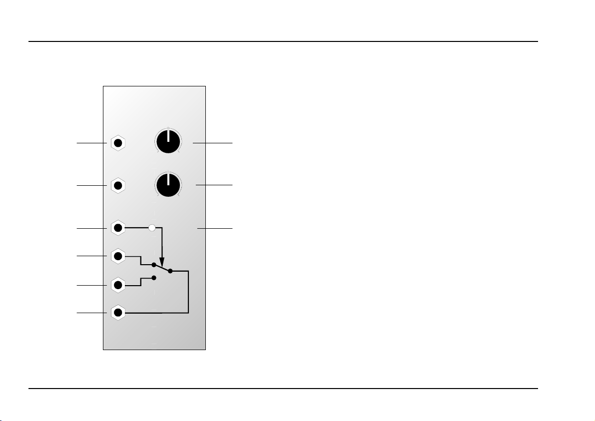
Voiced/Unvoiced Detector overview
A-129 /5
Voiced / Unvoiced Detec.
Speech
Input
VUV
Gain
10
Speech
Output
0
10
Gate
Output
0
Treble Boost
Unvoiced
Unvoiced
Input
Voiced
Input
Voiced / Unvoiced
Output
➀
➁
➂
Controls:
Gain : gain control for the speech input
1
signal patched into socket !
Treble Boost : control to increase the treble content
2
of the speech input signal
3 LED : LED indicator to show the presence
and relative strength of the unvoiced
signal
In / Outputs:
Speech Input
!
Speech Output
"
Gate Output : gate output, active during un-
§
Unvoiced Input
$
Voiced Input : input for voiced carrier signal
%
Voiced / Unvoiced Output: output for the carrier signal:
&
: input for speech signal
: output for speech signal after
amplification and treble boost
voiced sections of the sound
: input for unvoiced carrier signal
depending on the status of the
switching, it sends out the carrier signal present at sockets
or
%
$
2
Page 3

doepfer
System A - 100
Voiced/Unvoiced Detector
A-129 /5
3. Controls
1 Gain
Use control 1 to set the level of input gain for the
speech signal at socket !.
2 Treble Boost
Control 2 is used to increase the level of the high
frequencies
this control makes speech more easily intelligible.
H To produce the best results, please also look
3 LED
This LED indicator 3 shows the status of the switching in the voiced / unvoiced detector:
LED on : "Unvoiced"
•
LED off : "Voiced"
•
in the speech signal input. Often, using
at the general instructions (chapter 5) in the
manual for the main vocoder modules, A-129
/1 and A-129 /2.
4. In / Outputs
! Speech Input
The speech signal is patched into
Speech-input !
" Speech Output
Speech output " puts out the amplified and equalised
(treble-boosted) speech input signal. This output is
patched to the speech input socket on the A-129 /1
analysis module.
§ Gate Output
Gate output
the status of the voiced/unvoiced detector:
• "Unvoiced" (LED 3 on) : "high"
"Voiced" (LED 3 off) : "low"
•
You can use this gate signal for more elaborate sound
manipulation (see 5. User examples).
§ puts out a gate signal, depending on
.
3
Page 4

A-129 /5
Voiced/Unvoiced Detector
System A - 100
doepfer
$ Unvoiced Input
This unvoiced carrier signal input $ is used to patch
in the sound source you wish to use for the carrier
signal for unvoiced sounds.
As a rule, you’d tend to use the output from a noise
module (A-117, A-118), a high-frequency sawtooth
wave, or the 6 Oscillator output from an A-117 module.
% Voiced Input
This voiced carrier signal input
the sound source you wish to use for the carrier
signal for voiced sounds.
Usually, you’d tend to find a low-mid frequency VCO or
mix of several VCOs doing this job.
is used to patch in
%
& Voiced / Unvoiced Output
Depending on the status of the voiced/unvoiced detector switching,
socket $ or %.
output &
relays the input signal from
5. User examples
Vocoder block diagram including A-129 /5
The way the A-129/5 should be patched into the whole
vocoder system is shown in fig. 2 (see next page).
Smoothing Voiced / Unvoiced transitions
Whereas the A-129/5’s internal switch produces an
abrupt change from voiced to unvoiced carrier and
vice versa, it’s possible to patch the gate output to a
slew limiter, invert one of the carrier VCAs, and produce a smooth transition.
Gate Out
A-129 /5
A-170
A-117
A-118
A-110
A-111
A-175
A-130
A-130
A-138
to
Speech Input
of A-129 /1
fig. 1: smoothing the change of carrier signals
4
Page 5

doepfer
A-119
A-117
A-118
A-110
A-111
Speech
Gain
Input
Speech
Treb.
Output
Boost
A-129 /5
Unvoiced In
Voiced In
Unv./Voic. Out
LP
Speech
In
BP 1
BP 2
A-129 /1
System A - 100
Freeze
Man.
Contr.
Slew
Input
Rate
Follow
Slew
Slew
CV
Freeze
A-129 /4
Slew Control
Out
Slew Contr. In
Atten.
CV
In 1CVOut 1
Offset
A-129 /3
Voiced/Unvoiced Detector
LP
Instr.
In
BP 1
Voc.
BP 2
Out
A-138
A-129 /2
A-129 /5
BP 12
BP 13
High
Out
: diagram showing how to patch the A-129 /5
fig. 2
HP
BP 12
BP 13
HP
5
Page 6

A-129 /5
Voiced/Unvoiced Detector
System A - 100
doepfer
6
 Loading...