

Page 1

doepfer
System A - 100
Modular Vocoder
A-129 /3/4
1. Introduction
The A-129 /x series of modules is a modular vocoder. The crucial components are the A-129 /1
(analysis section) and A-129 /2 (synthesis section).
Module A-129 /3 adds a Slew Limiter to the vocoder.
It includes 5-way Attenuators, 5-way Offset Genera-
, and a
tors
voltages at the five CV inputs simultaneously).
Using the A-129 /3 just on its own, two functions are
available:
Attenuator: whatever signal is patched into the
•
CV input can be attenuated by your chosen amount
before being sent to the CV output. The attenuation
is set with a control knob.
• Offset Generator: whatever signal is patched into
the CV input will have an offset voltage added to it
before being sent to the output. The offset is
variable with a control knob.
To use the Slew Limiter section of the 129 /3, you need
to have module
well. It has several dedicated functions, and gives you
control over the following slew limiter functions:
Slew Limiter
A-129 /4 (Slew Limiter Controller
(which works on all the
) as
Manual control of the slew rate
•
CV control of the slew rate, with an input attenuator
•
• Choice of three functions: "Follow", "Slew" and
"Freeze"
• “Freezing” the output voltages for the duration of a
gate
H This set of functions is operated by the Slew
Limiter Controller, A-129 /4.
Usually, the slew limiter is patched between the CV
outputs of the analysis section and the CV inputs of
the synthesis section (see chapter 5, User examples).
You can also use module A-129 /3, particularly in
combination with A-129 /4, for other purposes. For
example, using the A-129 /2 synthesis section, you
can make a filterbank.
1
Page 2
A-129 /3/4
Modular Vocoder
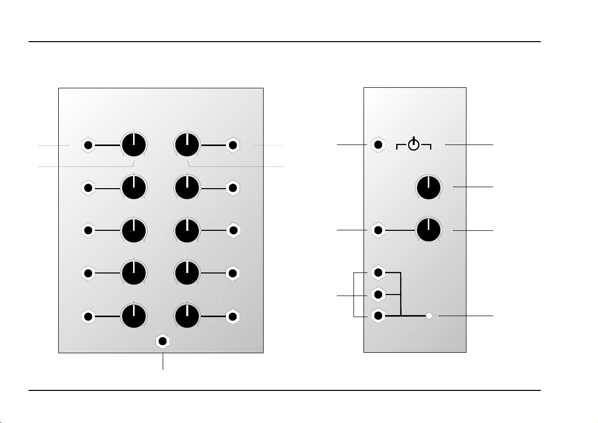
2. A-129 /3, /4 - Overview
System A - 100
doepfer
➀
A-129 /3
Attenuator Offset
CV In 1
0
CV In 2
0
CV In 3
0
CV In 4
0
CV In 5
0
Slew Control Input
Vocoder Slew-Limiter
CV Out 1
10
10
10
10
10
10
0
CV Out 2
10
0
CV Out 3
10
0
CV Out 4
10
0
CV Out 5
10
0
➁
A-129 /4
SLC
Slew Limiter Controller
Free ze
Ctr. Input
Freeze
Manual
Slew
Rate
Slew CV
Slew
Follow
0
0
Slew
Control
Outputs
10
10
➂
➃
➄
➅
2
Page 3

doepfer
System A - 100
Modular Vocoder
A-129 /3/4
A-129 /3
In- / Outputs:
CV In 1 ... CV In 5
!
CV Out 1 ... CV Out 5
"
Slew Control Input : Slew rate CV input; to
§
Controls:
Attenuator : Attenuator for the CV input
1
2 Offset : Offset control for the CV
: CV inputs
: CV outputs
access the slew limiting capabilities, patch the A-129 /4
output & into it.
output
A-129 /4
In- / Outputs:
Freeze Control Input
$
Slew CV :Slew rate control voltage
%
Slew Control Outputs: 3 internally linked CV out- puts
&
Controls and indicators:
Switch : Selector switch (3-position)
3
4 Manual Slew Rate : Knob for manual control of
Slew CV : Attenuator for output
5
6 LED : Indicator showing slew rate
: Gate input for controlling the
freeze function
input
to control slew rate
to choose "Freeze", "Slew",
or "Follow"
the slew rate
%
3
Page 4

A-129 /3/4
Modular Vocoder
System A - 100
doepfer
3. Controls and indicators
1 Attenuator
Use Attenuator 1 to lower the signal at the corresponding output !. At a setting of 0, the input signal is
completely switched off At a setting of 10, the signal
amplitude is completely unattenuated.
2 Offset
Control 2 sets the offset which you want to add to the
input signal. The offset control range goes from 0 V to
+5 V.
3 Switch
Switch 3 lets you
limiter works (see Fig. 1):
• Freeze : The instant you switch to this position, the
• Slew : The instant you switch to this position, the
select the mode
signal at the output is ‘frozen’ - a process
similar to what happens with the A-148
Sample & Hold.
slew limiter function
in which the slew
is selected.
• Follow
CV
Out
CV
In
FSFPos.
Fig. 1: The three slew limiter functions
H
: The instant you switch to this position the
output signal follows the input signal.
SlewFollow Freeze
(Attenuator = 10, Offset = 0)
In the "Slew" position, you can still freeze the
signal by sending a gate pulse to input
(see $ Freeze Control Input).
4 Manual Slew Rate
This control sets the slew rate of the slew limiter - the
steepness of the falling and rising edges of the waveform (see Fig. 2).
$
4
Page 5

doepfer
CV
Out
αααα
CV
In
: Slew rate explanatory diagram
Fig. 2
CV
Out
CV
In
αααα
System A - 100
(Attenuator=10, Offset=0)
With the control set at 0, the output signal is identical
to the input.
H The precise slew rate is decided by a com-
bination of the position of control 4, the control voltage available at input %, and the position of attenuator 5.
Modular Vocoder
A-129 /3/4
5 Slew CV
The amplitude of the control voltage at input % is
controlled with this attenuator 5.
6 LED
The LED indicates the mode of the slew limiter signal
at output &:
• dim : freeze
• bright : follow
5
Page 6

A-129 /3/4
Modular Vocoder
System A - 100
doepfer
4. In- / Outputs
! CV In 1 ... CV In 5
Sockets ! are CV inputs. This is where you patch in
the voltages you would like to modify - ie, attenuate,
offset, or smooth out by slew limiting.
" CV Out 1 ... CV Out 5
Sockets " are CV outputs, at which the modified
signals are available.
Each output signal is affected by a combination of
the attenuator, offset and slew limiter functions
§ Slew Control Input
Socket § is the input for the CV generated by the
A-129 /4 Slew Limiter Controller.
This input should be connected with output & on the
A-129 /4.
This is a specialised control signal which must
come from the A-129 /4
other modules won’t make sense.
. Connecting signals from
.
$ Freeze Control Input
A gate signal at input $ freezes the slew limiter’s
output signal (see Fig. 3).
H
CV
Out
CV
In
Freeze
Contr.
In
Fig. 3: Using a gate signal to freeze a voltage
This function is only active when the switch
is in the ‘slew’ position.
3
6
Page 7

doepfer
System A - 100
Modular Vocoder
A-129 /3/4
% Slew CV
Input % is where the CV should be patched in to
control the slew rate. The amplitude of the CV can be
set with the attenuator 5 if required.
& Slew Control Outputs
Sockets & are the slew limiter controller’s outputs.
They’re internally connected (a sort of mini-multiple),
and are designed to provide the control voltage to the
A-129 /3.
Connect one of the outputs to an A-129 /3 control
input.
5. User examples
Basic layout
Fig. 4 shows the standard layout for using the
A-129 /3 and A-129 /4. The A-129 /3 is inserted into
the control voltage chain, sandwiched between the
analysis and synthesis sections.
For total control of a 15-band vocoder, you need three
A-129 /3 modules. It’s quite possible to control the
slew limiter function of these three with one Slew
Limiter Controller A-129 /4. There’s also the option,
though, of using up to three, to treat different bands of
the vocoder in different ways.
The standard layout in Fig. 4 provides the following
control functions:
• CV to control the level of one or more vocoder
channels or bands (using the attenuator),
Smoothing the transition between vowels (slew li-
•
miter function),
• Vowel hold (freeze),
• Transposing vocoder channels (offset).
7
Page 8

A-129 /3/4
Modular Vocoder
System A - 100
doepfer
Freeze
Man.
Contr.
Slew
Input
Rate
Follow
Slew
Slew
CV
Freeze
A-129 /4
Slew Control
Out
Speech
In
BP 1
BP 2
Slew C ontr. In
Atten.
CV
LP
In 1
CV
Out 1
Offset
Instru ment
In
LP
BP 1
BP 2
Voc.
A-129 /3
A-129 /1
BP 12
BP 13
HP
A-129 /2
BP 12
BP 13
HP
Abb. 4: Basic set-up for the A-129 /3 and A-129 /4
Out
Further adventures in vocoder control
Using the layout in Fig. 4 (and also not forgetting
the tips and suggestions for experimentation in the
A-129 /1 and A-129 /2 manuals), you should be
able to produce all the most widely-used vocoder
effects. By patching in other modules, though, you
should be able to go ‘one step beyond’.
For a start, the voltages for the synthesis section
don’t have to come from the analysis section.
Possible choices for modulation sources from
which to control certain channels within the vocoder might include:
• ADSRs (A-140, A-141) for envelope control of
timbres
LFO's (A-145, A-146, A-147) for strange repea-
•
ted vocal timbres
• Sample-and-hold (A-118) for random vowel
sounds
Shepard-Generator (A-191) for continuous filter
•
effects
• Using an A-191 to control various vocoder
channels via MIDI - for instance aftertouch or
velocity.
8
Page 9

doepfer
System A - 100
Modular Vocoder
A-129 /3/4
P
Because as a modular vocoder the A-129 is
totally open-ended, it would be wrong to be
prescriptive about its use. Better to appeal to
your sense of adventure and experimentation. Particularly when you add other modules into the equation, the A-129 should enable you to create some extraordinary
sounds.
P Especially to begin with, though, don’t forget
the sound source and signal processing tips
and suggestions in the basic vocoder modules’ manuals.
A-129 /2 as a filter bank
The vocoder’s synthesis section can be used in conjunction with the A-129 /3 as a
filter bank
The A-129 /3’s offset controls govern the intensity of
the individual frequency bands within the total audio
spectrum (the output of the synthesis section).
You can also create a sort of voltage controlled filter
bank by using CVs from a wide range of modules to
set or modulate the levels of the frequency bands.
See user examples in the basic modules’ manuals,
and ‘Further adventures’ in this manual.
(see Fig. 5).
Atten.
CV
In 1CVOut 1
Offset
Instrume nt
In
A-129 /3
LP
3x
BP 1
BP 2
Voc.
Out
A-129 /2
Atten.
A-129 /3
CV
In 5CVOut 5
Offset
BP 12
BP 13
HP
Fig. 5: A-129 /2 and A-129 /3 as a filter bank
9
Page 10

A-129 /3/4
Modular Vocoder
System A - 100
doepfer
10
 Loading...