

Page 1

doepfer
System A - 100
Modular Vocoder
A-129 /1/2
1. Introduction
The A-129 /x series of modules forms a modular
vocoder. ‘Vocoder’ is an abbreviation of ‘voice coder’.
The basic components are an analysis section
(A-129 /1) and a synthesis section (A-129 /2).
Like a ring modulator, the vocoder needs two input
signals: a speech element which serves as the raw
material for the tonal shaping, and is patched into the
analysis section; and a
ched via the instrument input into the synthesis section.
The speech signal is chopped up and analysed in the
A-129/1 module, and then combined with the carrier
signal in the A-129/2 synthesis section. As a result of
this procedure, the carrier signal assumes the tonal
character of the speech signal, but with its own pitch
maintained.
Since the A-129 is a modular vocoder, and the
connections between the analysis and synthesis section are external, using patch-leads, you can use this
carrier signal
, which is pat-
interface to
attenuator, slew limiter, CV-to-MIDI / MIDI-to-CV interfaces,, inverter, etc.).
The
Five-way VC slew limiter / offset generator /
attenuators (A-129 /3) and Slew controllers (A-
129/4) are particularly designed for this purpose.
There’s also the possibility of connecting the frequency
bands of the analysis and synthesis sections arbitrarily, so that, for instance, a low frequency band in the
speech signal can control a high frequency band in the
carrier signal.
The
Voiced / unvoiced detector (A-129 /5)
cognise voiced and unvoiced sections in the speech
signal, and switch the carrier signal accordingly.
The A-129 /2 synthesis section can also be used as a
stand-alone voltage-controlled filter bank (see
chapter 6, User examples).
patch in
your choice of
modules
can re-
(eg.
1
Page 2
A-129 /1/2
Modular Vocoder
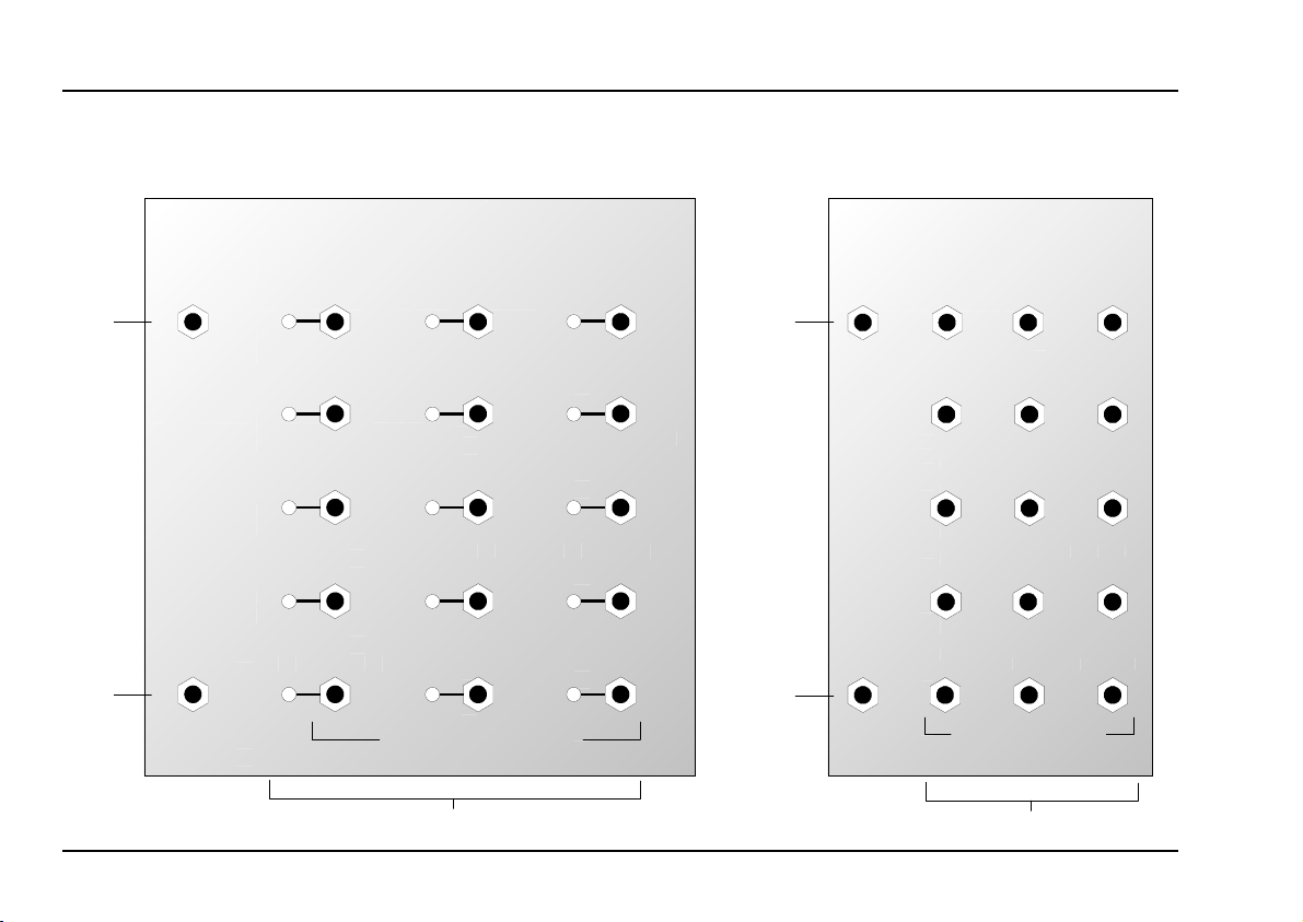
2. A-129 /1, /2 - Overview
System A - 100
doepfer
Speech
Input
High Pass
Out
A-129 /1
VOCODER ANALYSIS SECTION
Low Pass
Band 1
Band 2
Band 3
Band 4
VOC-A
Band 5
Band 6
Band 7
Band 8
Band 9
Control Voltage Outputs
Band 10
Band 11
Band 12
Band 13
High Pass
A-129 /2
VOCODER SYNTHESIS SECTION
Instrument
Input
Vocoder
Output
Low Pass
Band 1
Band 2
Band 3
Band 4
Band 5
Band 6
Band 7
Band 8
Band 9
Control Voltage Inputs
VOC-S
Band 10
Band 11
Band 12
Band 13
High Pass
2
Page 3
doepfer
System A - 100
Modular Vocoder
A-129 /1/2
In / Outputs:
A-129 /1
Speech In : Input for the speech signal
!
CV Outputs
"
High Pass
§
A-129 /2
Instrument In : Input for the instrument signal
$
CV Inputs : 15 CV inputs
%
Vocoder Out
&
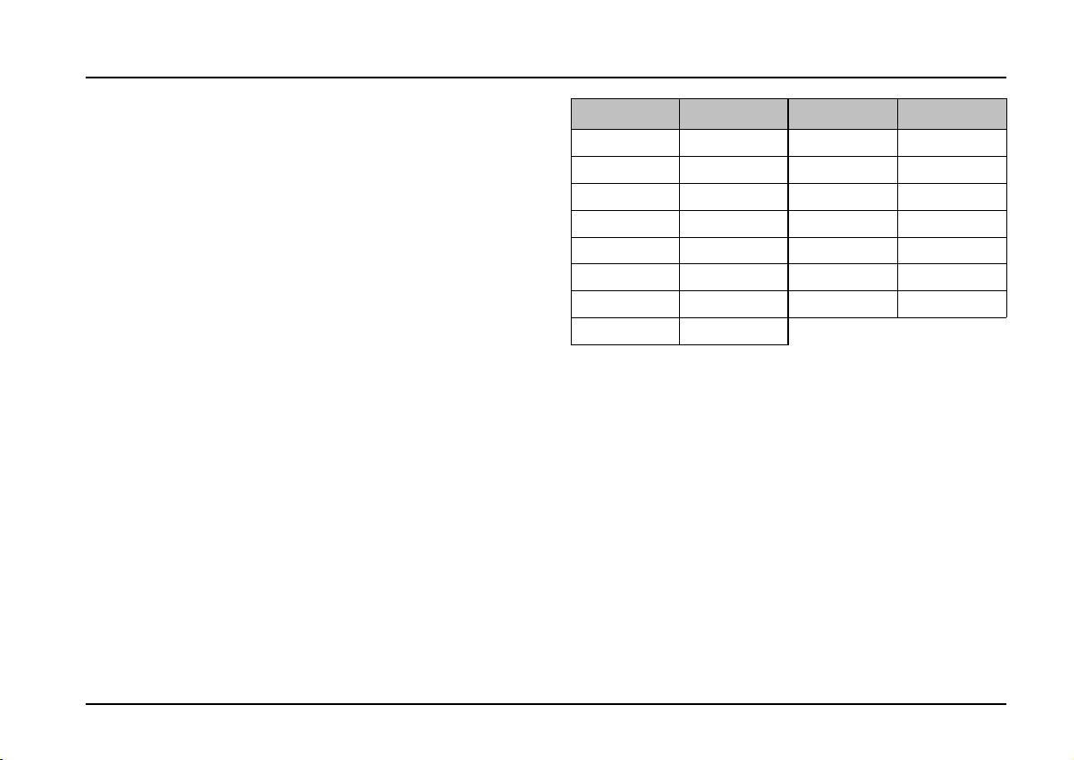
The following Table 1 shows the cut-off frequency of
the low pass filter, the middle frequency of the band
pass filters (Band 1 to Band 13) and the cut-off
frequency of the high pass filter.
: 15 CV outputs with control LEDs
: Signal output from the high pass
filter
: Audio output from the vocoder
Filter Frequency Filter Frequency
Low Pass
Band 1
Band 2
Band 3
Band 4
Band 5
Band 6
Band 7
100 Hz
120 Hz
160 Hz
230 Hz
330 Hz
500 Hz
750 Hz
1.1 kHz
Band 8
Band 9
Band 10
Band 11
Band 12
Band 13
High Pass
1.3 kHz
1.6 kHz
2.3 kHz
3.3 kHz
5 kHz
7.5 kHz
10 kHz
Tab. 1: Filter frequencies in the analysis and synthe-
sis sections
3
Page 4

A-129 /1/2
Modular Vocoder
System A - 100
doepfer
3. Basic principles
The fundamental modules in this vocoder are the
analysis section A-129 /1
A-129 /2 (see Fig. 1).
The
speech signal
being passed through a set of steeply sloping band
pass filters, with a low- and high- pass filter mop-
ping up the bottom and top frequencies respectively.
Attached to each of these filters is an envelope follower, which analyses the audio signal level passing
through, and sends a proportional voltage out of its
dedicated CV output (see below for further details).
The instrument signal is likewise sent through
another set of steeply sloping band pass filters, and a
low- and high-pass filter in the A-129 /2 synthesis
section, and is split into individual frequency bands.
This time, each filter has an associated VCA (voltage
controlled amplifier), which is governed by the voltage present at its
CV input
In this way, each frequency band in the instrument
signal has the dynamics of the corresponding band
from the speech signal superimposed onto it. The
pattern of the speech signal is thus re-constructed
from the tonal raw material of the instrument signal.
and the
synthesis section
is analysed in the A-129 /1, by
.
The closer the audio spectra of the speech and carrier
signals are, the more speech-like the resulting reconstruction.
Speech In Instrument In
VCA
LPF
LPF
BPF 1
BPF 13
HPF
Analysis A-129 /1 Synthesis A-129 /2
EF
EF
EF
EF
High
Pas s
Out
BPF 1
BPF 13
HPF
VCA
VCA
VCA
Mix
Voc.
Out
Fig. 1: Block diagram of the A-129 analysis and
synthesis sections
4
Page 5

doepfer
System A - 100
Modular Vocoder
A-129 /1/2
H
In most standard vocoders the voltage signals from the analysis section are fed
straight into the synthesis section. With the
A-129 modular vocoder, they are patched
externally via 15 leads.
That means it’s possible to modify the control
voltages by patching any sensible choice of
module (for instance attenuators, slew limiters, LFO, CV-MIDI / MIDI-CV interfaces,
inverters, etc.), between the analysis and
synthesis sections. Not-so-sensible choices
may produce interesting results, too.
It’s also possible to interconnect control voltages to synthesis section inputs in a nonstandard way, so that for instance the output
from a low frequency band from the speech
signal can control a high frequency element
of the carrier signal.
With a modular vocoder, the only constraints
on experimentation are the limits of your
imagination (and you can also always have
a look at chapter 6, User examples).
4. In / Outputs
! Speech In
Socket ! is the input to the analysis section. This is
where the speech signal is patched in.
Don’t forget that the speech signal needs to be at the
high level the A-100 uses internally. Plugging a
microphone directly in to the vocoder won’t work.
You need to use an A-119 External Input module, into
which you can plug a microphone or other external
signal. Then the output of the A-119 can be patched
into input socket ! on the analysis section.
"
Low Pass
These are the CV outputs " from the analysis section, whose voltages are determined by each filter’s
envelope follower. Each CV output has an LED
connected to it, showing the strength of the voltage
generated.
•
Band 1
to
Band 13
•
High Pass
5
Page 6

A-129 /1/2
Modular Vocoder
System A - 100
doepfer
§ High Pass
Socket § on the analysis section is the high pass
filter output. Unlike the other sockets, this is an audio
output
which the high pass filter lets through. This is most
usually added to the vocoder output, to make the
modified carrier signal more speech-like still, by including these high frequency elements of the sound.
, which sends out the part of the speech signal
$ Instrument In
Socket $ on the synthesis section is where you patch
in the instrument that will provide the carrier signal
(see below).
P Experiment with different sorts of sound for
the carrier signal, for instance
• sawtooth or square waves from a VCO,
• noise (A-118),
• digital noise (A-117).
H
%
The
the control voltages from the analysis section are
patched in.
With an
module, you can switch the carrier signal
depending on whether a speech signal is
present.
Low Pass
CV inputs %
A-129 /5
•
Band 1
on the synthesis section are where
voiced / un-voiced detector
•
Band 13
•
High Pass
& Vocoder Out
Output & on the synthesis section is the audio output
for the whole vocoder.
6
Page 7

doepfer
System A - 100
Modular Vocoder
A-129 /1/2
5. User examples
Basic principles
To get the best results from the vocoder, it’s essential
to take note of the following important points:
• For professional results, the quality of the speech
signal is crucial.
If you use a cheap and cheerful microphone,
connecting it up to the vocoder via the A-119 won’t
guarantee good results.
Any unwanted noise (rumble, airborne background
sounds, etc.) will greatly reduce the effectiveness
of the vocoding.
According to various musicians including Kraftwerk,
the speech signal is easier to use if it isn’t live, but
has been taped or sampled, and thus has reliable
levels and signal-to-noise - and is repeatable.
For early experiments, radio news stations provide
•
good raw material, because they are nearly always
putting out a steady stream of human speech.
• For the best results, speech and carrier signals
need to have similar frequency spectra. A quiet
female voice, or a child’s, needs a different carrier
signal compared with a low-register male voice. If
you use a VCO as the carrier signal, you can tune
it to find the ideal frequency.
Basically, the instrument’s carrier signal needs to
•
be as overtone-rich as possible, with a dense audio
spectrum. With a VCO the sawtooth output is best
suited to the task. An exact square wave has only
half as many harmonics, and triangle and sine
waves are completely unsuitable (see the notes to
the A-110 and/or A-111).
For professional results, it’s recommended to use a
•
graphic or parametric EQ to equalize the speech
signal to produce the most speech-like results at
the vocoder’s output. Good results can also be
obtained using computer-generated speech (as on
the A-100 demo CD).
In addition, we plan to bundle an audio cassette of
•
speech with each vocoder.
7
Page 8

A-129 /1/2
Modular Vocoder
System A - 100
Using just the basic modules
Just with the A-129 /1 and A-129 /2 modules (and an
A-119 external input), all the common vocoder effects
can be produced (see Fig. 2).
First patch all the CV outputs on the analysis
D
section to their respective CV inputs on the synthesis section (band 1 to 1, 2 to 2, and so on)
D Use an A-119 (External Input) to patch an audio
signal (see above, chapter 5, Basic Principles) into
the speech input socket of the analysis section at
normal A-100 operating level.
Experiment with different audio signals for the car-
D
rier frequency (instrument input), for instance:-
• different overtone-rich waveforms from a VCO,
• pink or coloured noise from an A-118,
• digital noise from an A-117,
• ring modulator outputs,
• two VCOs modulated in the audio range by FM
or AM.
doepfer
A-138
* : VCO
Noise
Dig. Noise
Ring Mod.
AM
FM
...
Audio *
Out
Speech
In
LP
BP 1
BP 2
A-119
LP
BP 1
BP 2
Instru m.
In
Voc.
A-129 /1 A-129 /2
BP 12
BP 13
High
HP
Out
: Basic vocoder schematic
Fig. 2
BP 12
BP 13
HP
"Frequency displacement"
If instead of patching the outputs from the analysis
section to their ‘proper’ respective inputs in the synthesis section, you swap them about instead, interesting
frequency displacements occur in the vocoder output.
D Swap the connections between analysis and syn-
thesis sections (see above).
8
Fig. 3 shows some simple variations; experiment
withall sorts of other possibilities.
Page 9

doepfer
System A - 100
Modular Vocoder
A-129 /1/2
Speech
In
LP
BP 1
BP 2
Instrument
In
LP
BP 1
BP 2
A-129 /1 A-129 /2
Speech
In
Speech
In
BP 11
BP 12
BP 13
HP
LP
BP 1
BP 2
BP 12
BP 13
HP
Instrument
In
LP
BP 1
BP 2
Instrum.
A-129 /1 A-129 /2
BP 11
BP 12
BP 13
HP
BP 12
BP 13
HP
Fig. 3: "Frequency displacement"
Voc.
Out
In
Voc.
Out
"Freq. down"
"Freq. up"
"Chopped up” speech
The patch in Fig. 4 produces chopped-up speech: the
vocoder chops speech up rhythmically, in time with the
trigger signals. The vocoder output is patched into a
VCA, which is controlled by a rhythmical pulse from an
ADSR (A=0, R=0, D and S to taste). The source of the
trigger signal could be an MAQ 16/3, Schaltwerk or
trigger from a MIDI sequencer via a MIDI Interface
such as the A-190.
Speech
In
LP
BP 1
BP 2
A-129 /1 A-129 /2
BP 12
BP 13
HP
Instrument
In
LP
BP 1
BP 2
BP 12
BP 13
HP
Voc.
Out
VCA 1
ADSR
Rhythmic trigger
Fig. 4: Rhythmically chopped-up speech
9
Page 10

A-129 /1/2
Modular Vocoder
System A - 100
doepfer
Using with the other modules ( /3, /4, /5)
While extremely usable vocoder sounds can be produced with just the two basic modules, total flexibility and
unlimited possibilities are offered by adding on the
extra modules (A-129 /3, A-129 /4, A-129/5).
Full user instructions will be found in the modules’ own
manuals.
A-129 /2 as a MIDI-controlled filterbank
The vocoder’s synthesis section can also, in conjunction with a special A-191 MCV16 module, be used as
a MIDI-controlled filterbank (see Fig. 3).
The level of each of the control voltages (Input &)
determines the relative level of each of the frequency
bands at the A-129/2’s output socket %.
These CVs are patched from a special A-191 MIDI-
CV-Interface (with 16 CV outputs and no MIDI-LFO)
and are controlled by various continuous controllers see the A-191 manual for details.
Audio In
VCA
MIDI
MIDI In
A-191 *
CV 1
CV 1
CV 15
CV 16
LPF
BPF 1
BPF 13
HPF
VCA
VCA
VCA
A-129 /2
* Special version
: The A-129 /2 as a MIDI-controlled filterbank
Fig. 3
Mix
Audio
Out
10
 Loading...