

Page 1
doepfer
In Level
Audio
A-127
Audio
In
ext. CV
VCF 1
Audio
Out
VCF 2 VCF 3
Mix Out
VCRF
LFO Frq.
CV Ampl.
VCF Frq.
Resonance
Audio Lev.
Original
System A - 100
1. Introduction
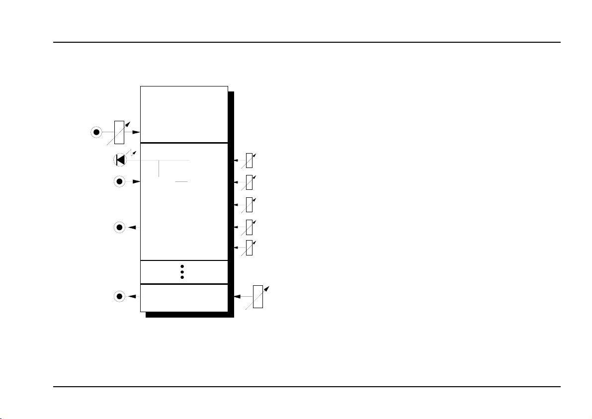
Module A-127 is a Voltage-Controlled Triple Resonance Filter
filters with one common input.
For each of the filters, the
nance can be manually controlled, and in addition
the filter frequency can be voltage controlled. Each
filter has its own audio output. There is also a Mix
output which takes your chosen amounts of each of
the three filter outputs and the original signal - set by
the Audio Level controls - and outputs them from one
socket.
Each of the filters also has an internal LFO (a triangle
waveform) for modulating the filter, and there are
controls for LFO frequency and amplitude. Instead of
the LFO, an external control voltage can be used,
whose amplitude can be manually controlled.
H
Triple VC Resonance Filter
), consisting of three separate
filter frequency
There is an alternative scenario:- each of the
three filters can also be configured as a
12dB low-pass filter
trol. To do this, a jumper has to be repositioned on each of the three circuit boards
(see chapter 7, Appendix).
with resonance con-
A-127
band pass
and
Reso-
1
Page 2
A-127
Triple VC Resonance Filter
System A - 100
doepfer
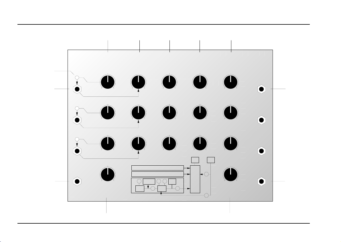
2. VCRF - Overview
A-127 VCRF
➃
ext. CV
1
2
3
Audio
In
➁
LFO Frq.
0
0
0
0
Audio In
Level
➂ ➄ ➅ ➆
Triple Voltage Controlled Resonance Filter
CV Ampl. VCF Frq. Resonance Audio Level Audio
10
10
10
10
10
0
10
0
10
0
1 s ame circuit
2 s ame circuit
3
F
ext. CV Out
LFO
A L
0
0
0
F Q
VCF
10
10
10
0
0
0
Out In
M
I
X
10
0
10
0
10
0
L
0
Original
L
Out
VCF 1
10
VCF 2
10
VCF 3
10
Mix
10
➀➇
2
Page 3

doepfer
System A - 100
Triple VC Resonance Filter
A-127
Controls:
A. In Level : Input signal attenuator
1
per VCF:
LFO Frq. : LFO frequency control
2
3 CV Ampl. : Attenuator for external CV and/or
LFO amplitude
LED : LFO and/or external CV indicator
4
5 VCF Frq. : Filter frequency control
Resonance
6
Audio Level : Level control for audio output
7
Original : Control for setting the amount of
8
(*) For modules manufactured until end of 1998 control
7 affects both the individual outputs § and the mix
output $. For modules manufactured 1999 and later
control 7 affects only the mix output $, but not the
single outputs §.
: Filter resonance control
amplitude of the filter (*)
the original signal present at the
Mix output
$
In- / Outputs:
Audio In : Input to the filter
!
per VCF:
ext. CV : Filter frequency CV input
"
§ Audio Out : Filter output
Mix Out
$
:Mix output
3
Page 4
A-127
Triple VC Resonance Filter
System A - 100
doepfer
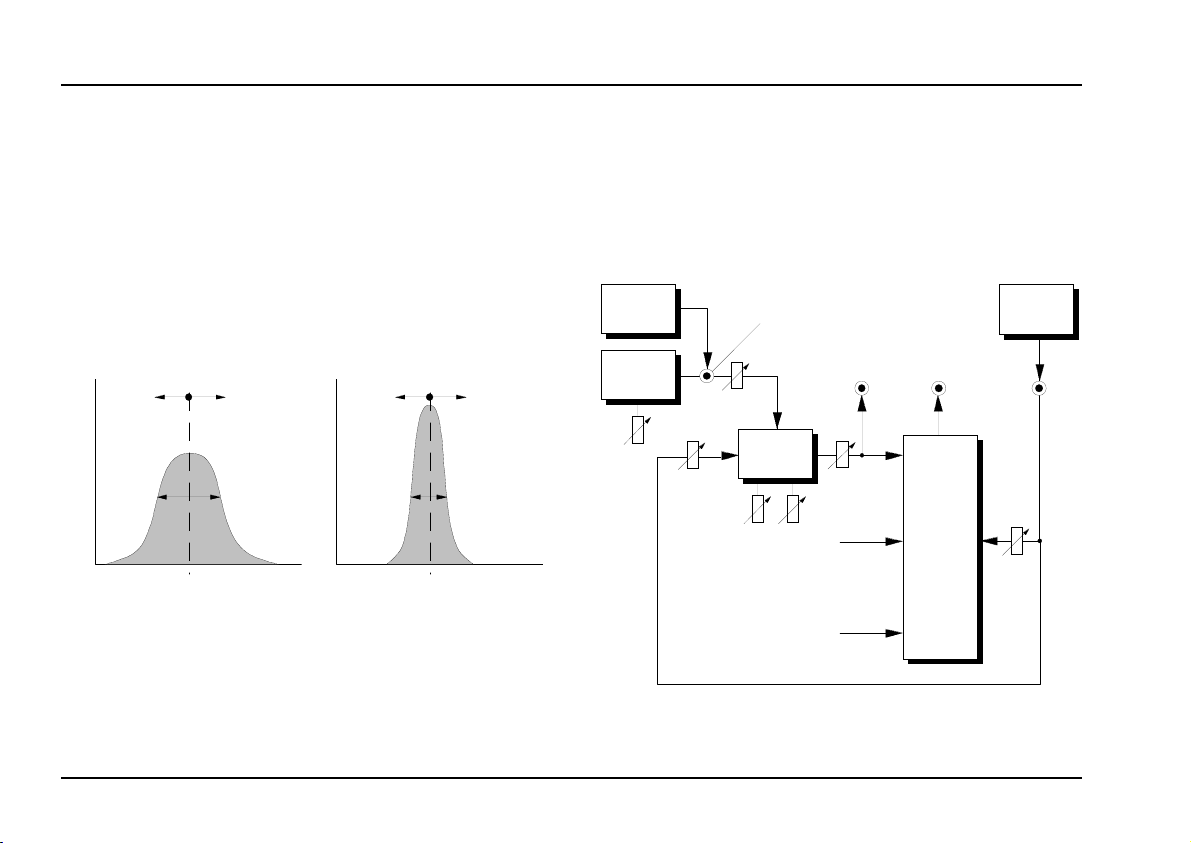
3. Basic function
The A-127 is a triple resonant filter containing three
band-pass filters each with controllable filter frequency
, resonance and amplitude. What a band-pass filter
f
M
does is to attenuate signals in frequency ranges both
above and below the filter frequency - referred to here
as the middle frequency - resulting in a bell-shaped
response curve (see fig. 1). In this way, a particular
part of the audio spectrum can be singled out.
Out
fig. 1: Frequency response of a band-pass filter
VCF Frq. / CV VCF Frq. / CV
f
M
Freq.
Out
M
with lower (on the left) and higher resonance
Freq.f
band let through, and the Audio Level control to set the
volume (see fig. 1).
To make it easier to understand how the A-127 is
configured, fig. 2 shows a block diagram of the
internal components.
ext. CV
LFO
ext. CV
"
Audio O ut§Mix Out
$
CV Ampl.
Audio
Audio In
!
3
Frq.
5
VCF
Res.
6
Level
7
1
Mix
2
Original
Frq.
2
In Level
1
8
3
For each filter you use the frequency control to determine the exact position along the frequency axis, the
resonance control to set the width of the frequency
4
fig. 2: Internal construction of the A-127 (from 1999
output § is not affected by the level control 7)
Page 5

doepfer
System A - 100
Triple VC Resonance Filter
A-127
4. Controls
1 Audio In Level
With the attenuator 1 you can set the
audio signals coming in to input ! .
The filter inputs are very sensitive, so it’s possible to
overdrive
(e.g. a VCO). With a VCO being input, overdrive
starts kicking in at about halfway on the attenuator
knob (1)’s travel.
the Filter with a normal A-100 signal level
H The module is set up at the factory so that
attenuator 1 doesn’t have any effect on the
Original signal level 8, so the effected sound (3
Filters) and "Original" sound can be controlled
separately, by 1 and 8 respectively (see fig. 1).
It’s possible to change this by altering a jumper
on the mixer circuit board (see chapter 7, Appendix), so that both the levels (Filter + Original)
can be controlled by attenuator 1 .
2 LFO Frq.
Potentiometer 2 gives control of the LFO frequency.
The frequency of the LFO’s triangle-wave oscillation
can be varied from c. 0.02 Hz (oscillation period c. 1
minute) to c. 20 Hz (oscillation period 1/20 sec).
level
of the
3 CV Ampl.
The
amplitude
with attenuator 3, and the source of this modulation
depends on whether anything is connected to socket
.
"
If the socket has nothing connected, the amplitude of
the internal LFO is controlled; if the socket does have
something connected, the amplitude of the external
control voltage
LED
4
LED 4 gives a visual indication of the modulation
signal produced by the LFO.
of the
modulation signal
is controlled.
is adjusted
5 VCF Frq.
Control 5 is used to set the filter frequency f
range: ~ 40 Hz to ~ 8 kHz).
The actual filter frequency is determined by the sum of
the voltages from the control knob and the modulation
signal (LFO or external control voltage).
(
M
6 Resonance
Control 6 is used to set the filter resonance. The
higher this control is set, the narrower the bandwidth
of the bandpass effect (see fig. 1).
5
Page 6

A-127
Triple VC Resonance Filter
System A - 100
doepfer
If the module has been re-configured to be a
pass filter, control 6 boosts the frequencies around
the filter cut-off point (see also the A-120 and A-122
low pass filter modules). Using the filter at high resonance to produce its own pitched tone (self-oscillation)
isn’t possible with this module.
low
7 Audio Level
Attenuator 7 adjusts the
each of the filters to be fed into the Mix signal at
output $.
amount of the signal
from
H For modules manufactured until end of 1998
control 7 affects both the corresponding individual output § and the mix output $. For modules manufactured 1999 and later control 7 affects only the mix output $, but not the single
outputs §.
8 Original
Whatever original signal was present at socket ! can
also be added into the internal mixer. The
the original signal fed into the mix output signal is set
by attenuator 8.
amount
of
H
The module is set up at the factory so that
attenuator 1 doesn’t have any effect on the
Original signal level 8, so the effected sound
(3 Filters) and "Original" sound can be controlled separately, by 1 and 8 respectively
(see fig. 1). It’s possible to change this by
altering a jumper on the mixer circuit board
(see chapter 7, Appendix), so that both the
levels (Filter + Original) can be controlled by
attenuator 1 .
5. In- / Outputs
! Audio In
This is the socket into which you connect the audio
signal which you want to be filtered.
" ext. CV
Socket " is the
lating the filter via external voltage control (ADSR,
LFO, sequencer - see chapter 7, User Examples).
This is a
tion is made, the internal LFO serves as the modulation source instead.
control voltage input,
normalled (switched) socket
used for modu-
. If no connec-
6
Page 7

doepfer
System A - 100
Triple VC Resonance Filter
A-127
§ Audio Out
Each filter Audio output § sends out the signal
processed by the particular filter. Despite what the
diagram on some of the early A-127 modules shows,
the Audio Level control 7 does also affect these
individual outputs, because the individual output comes after the Audio Level control in the circuit.
$ Mix
At socket $ the mixed output from the internal mixer
is available. That includes the output from each of the
three filters (with level from each filter set by control 7)
and the original signal (with level set by control 8).
6. User examples
By controlling filter frequencies with the internal LFO or
external voltages, the A-127 can produce extremely
complex filtering effects.
The control possibilities available with
lation sources are almost limitless.
Here are just a few examples:-
• LFO
other waveforms - not just triangle; LFO frequencies in the Audio- range
• ADSR
different envelopes for each of the individual filters;
complex filter sweeps
• MIDI Interface A-191
different MIDI controllers for each of the individual
filters: MIDI-controlled vowel sounds (see Examples below)
• Random-CV A-118
random filter settings
• Theremin A-178
filter settings by remote control!
Sequencer A-155 or MAQ 16/3
•
vocoder- and speech-like effects with specially shaped external CV sequences (see below)
external Modu-
7
Page 8

A-127
Triple VC Resonance Filter
System A - 100
doepfer
• S&H filter effects with an A-148
the A-148 Sample&Hold samples signals from modulation sources (LFO, Noise, Random, VCO, etc.)
at regular clock intervals (see fig. 3)
Clock Audio In
Mod.
Source
Mod.
Source
Mod.
Source
: S&H filter effects with an A-148
fig. 3
S&H
S&H
S&H
Clock
Clock
Clock
A-127
ext.
12 3
CV
Mix
Out
One of the A-127’s particular strengths is its ability to
bring out the formants that are crucial in re-creating
some sounds. It’s able to latch on to particular frequencies or ranges of frequencies which are characteristic
of an instrument, a room, or an acoustic effect, and
emphasise them within the whole frequency spectrum.
Equalisation is often used to suppress these formants
when a room’s acoustics need to be neutralised; but
the A-127 can actually work the other way, to simulate
a real room’s formants, and bring a sound alive.
A special application of this ability to build up formants
can be to simulate human speech - or more exactly,
human vowel sounds.
What happens when a person pronounces a vowel is
that the overtone-rich vocal cord sound sets off all
sorts of resonances in the mouth, nose and throat,
whose frequency depends mostly on the shape of the
mouth and position of the tongue.
The characteristic sound of each vowel is created by
formants - ranges of frequencies emphasised by the
mouth and throat creating resonant cavities which pick
out harmonics from the basic sound of the vocal cords.
The most important frequencies for formants in German vowel sounds is shown in fig. 4.
8
Page 9

doepfer
System A - 100
Triple VC Resonance Filter
A-127
uo aaouaei
f
+ u+ o
0.2 0.4 0.6 1.2 1.8 2.6 5.00.8
+ a
+ u
+ o
[kHz]
fig. 4: German vowel formant frequency range.
In the patch in fig. 5, this process is simulated by two
of the A-127’s band-pass filters, with the sawtooth
output from a VCO acting as the sound source. An
A-155 sequencer controls the A-127. Pitch is controlled by a keyboard.
The resonance of both of the band-pass filters should
be set quite high. The sounds from this patch will be
more realistic if the individual sounds slide from one to
the next (using the Glide Control on the A-155).
P It’s also possible to use non-harmonic
sound spectra (e.g. ring modulator signals)
for further experimentation.
Another source for discovering the formant frequency
range of English language vowel sounds is Allen
Strange's book Electronic Music. Here, he specifies
three centre frequencies for the formants for each of
the vowel sounds (see Table 1).
Band ee i e ae ah aw u oo A er
270 390 530 660 730 570 440 300 640 490
1
1990 1840 1720 1090 1840 1020 870 1190 1350 -
2
3010 2550 2480 2410 2440 2410 2240 2240 2390 1690
3
Tab. 1: Band-pass filter frequencies 1 to 3 for the
production of male vowel sounds (from: Allen
Strange, "Electronic Music")
If you’re trying out the patch in fig. 5, then just use the
first two frequency settings in each set of three.
9
Page 10

A-127
Triple VC Resonance Filter
System A - 100
doepfer
CV
Clock
A-155
1 2 3 4 5 6 7 8
Trig. 1
Post Out 1
Post Out 2
fig. 5: Simulation of vowel sounds
Otherwise, three vowel formant frequencies can be
produced using either a MAQ 16/3 sequencer, with
three control voltages per step, or by running two
A-155 sequencers in parallel. In this case, you could
use the spare CV from the second A-155 for pitch
control (instead of an external keyboard) or to produce
different decay times, by using a VC-ADSR instead of
a standard ADSR.
VCO
A-127
ext. CV 1 2
Mix
Out
ADSR
VCA
10
Page 11

doepfer
7. Appendix
Altering the filter characteristics
System A - 100
Triple VC Resonance Filter
A-127
The
characteristics
the A-127 can be altered by changing the position of a
corresponding jumper on its three-pin connector on
the filter circuit-board.
The standard factory setting is for each of the filters to
be set to the bandpass position (labelled "BP").
You can, if you want, alter the response of each
individual filter
Versions 1 and 2 of the A-127 module:
Change Jumper J1 on the filter circuit board from
position "BP" to position "LP" (low pass) - see Fig. 6.
Version 3 of the A-127 module:
Change the position of Jumper JP5 on the filter circuit.
JP5 is located behind der filter output socket.
Even a toggle switch can be added to switch between
low pass and band pass for each filter.
of each of the indifividual filters in
, so that it is
12 db low-pass.
: A-127 filter circuit-board
fig. 6
(versions 1 and 2)
11
Page 12

A-127
Triple VC Resonance Filter
System A - 100
Changing how control 1 works
As standard from the factory, Attenuator 1 doesn’t
have any effect on the Original control 8, so that it’s
possible to adjust 1 and 8 independently.
Versions 1 and 2 of the A-127 module:
doepfer
To change this, you can alter the position of
J3 on the Mix circuit-board from "Pre" (the factory
default) to "Post" (see fig. 8). In this case, control 1
comes before the Original signal level control 8, and
so does affect both the filter and Original signals.
Version 3 of the A-127 module:
Change the position of Jumper JP4 on the mix circuit
board. JP4 is located right beside the Audio In Level
control.
Even a toggle switch can be added to switch between
pre and post setting of control ol 1.
12
Jumper
: A-127 mix circuit-board
fig. 8
(versions 1 and 2)
 Loading...