

Page 1
doepfer
System A - 100
1. Introduction
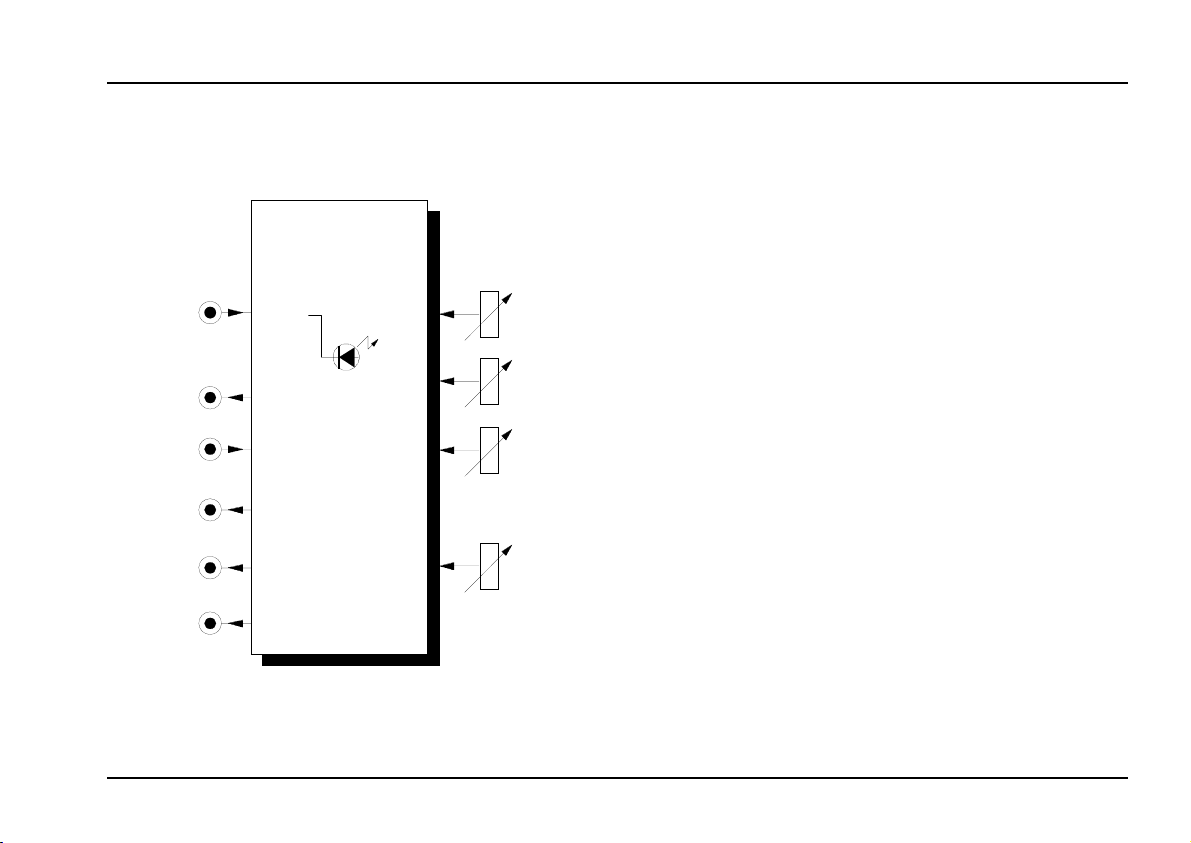
Module A-126 (VCFS) is a voltage-controlled frequency shifter.
VC Frequency Shifter
A-126
A-126
VC Frequ. Shifter
Audio
In
Audio
Out
CV
Up
Mix
Down
Overload
Level
Shift
CV
Mix
The amount of frequency shift can be varied from
about 50 Hz up to 4 kHz, either manually, or by voltage
control (via an attenuator).
The amount of input signal gain can be controlled
with the
The
upward- (Up)
signals are available at separate outputs, and also at
the Mix output, where a mix of the two frequency-
shifted signals is available, with the balance controlled
by a Mix knob.
The Audio Out socket provides an amplified but not
frequency-shifted version of the original input signal.
Level
knob.
and
downward- (Down)
shifted
1
Page 2
A-126
VC Frequency Shifter
System A - 100
doepfer
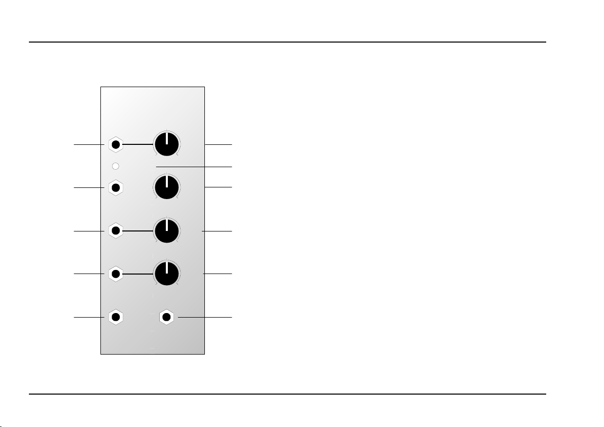
2. VCFS - Overview
A-126
VC Frequency Shifter
Audio In
0
Over load
Audio Out
CV
Mix
Output
Down
Output
0
0
0
VCFS
Up
Output
Level
10
Shift
10
CV
10
10
Mix
➀
➁
➂
➃
➄
Controls:
1
Overload : LED overload warning light for the
2
Shift : control for manual frequency-shifting
3
4
5
: gain control for the signal connected
Level
to input
input signal
: attenuator for the frequency-shifting
CV
control voltage at input
: control to balance the relative
Mix
amounts of Up and Down frequencyshifted signals at output
!
§
$
In / Outputs:
Audio In : audio input (line level)
!
Audio Out
"
: control voltage input for pitch-shifting
CV
§
Mix Output
$
Down Output
%
Up Output
&
: audio output (the original signal
amplified but not frequency-shifted)
: mix output for Up and Down signals
: output for just the downward-shifted
audio signal (Down)
: output for just the upward-shifted
audio signal (Up)
2
Page 3

doepfer
System A - 100
VC Frequency Shifter
A-126
3. Basic principles
Frequency shifting can slide an audio signal upwards
("UP Shift") or downwards ("DOWN Shift").
This is
the components of an audio signal are raised or lowered by an equal interval).
With frequency shifting, all the component harmo-
nics of a sound are shifted not by an equal musical
interval, but by the same frequency.
As a rule, the resulting output signal is very likely to
be
dissonant
altered not by a proportional amount, but by exactly
the same number of Hz. Think of a sawtooth with a
500 Hz fundamental, a first harmonic at 1 kHz, second
at 1.5 kHz, and so on. If the signal is shifted upwards
by 100 Hz the new fundamental will be 600 Hz, and
the overtones 1.1 kHz, 1.6 kHz, etc.. These overtones
are no longer perfect harmonics of the fundamental.
As with ring modulation, very complex, spectrally rich
sounds often result.
the same as
not
, because the overtone frequencies are
transposition
(in which all of
4. Controls
1 Level
Control 1 is used to set the amount of
of the input signal at socket !.
2 Overload
LED 2 lights up when the input signal
3 Shift
The amount of frequency shifting is set manuallywith
this control in a range from c. 50 Hz to 4 kHz.
4 CV
In addition to the manual control, the amount of frequency shifting can also be altered by a control voltage
patched into input §; the level of voltage control can
be set with attenuator 4.
amplification
overloads.
3
Page 4

A-126
VC Frequency Shifter
System A - 100
doepfer
5 Mix
Use control 5 to set the relative amounts of upwardand downward- shifted signals present at the mix
output $. If the knob is turned fully clockwise or
anti-clockwise, only one of the signals is audible:
Mix = 0
Mix = 10 : just the upward-shifted signal is heard
: just the downward-shifted signal is heard
5. In / Outputs
! Audio In
Socket ! is the frequency shifter’s audio input. Use it
to patch in the audio signal you want frequencyshifted.
" Audio Out
§ CV 1
Patch a control voltage for modulating the amount
of frequency-shift into socket §. The level of voltage
control is set with attenuator 4.
As a rule, a slowly-changing voltage (e.g. LFO, ADSR,
Random, etc.) or the CV output from a MIDI-CVInterface (e.g. A-190, A-191) is used for this.
$ Mix Output
Depending on the position of control 5,
contains a mix of the downward and upward
frequency-shifted signals.
output $
% Down Output
Output % contains just the downward frequency-
shifted signal.
& Up Output
Output &
shifted signal.
contains just the
upward frequency-
Output "
4
relays the
original signal
, amplified.
Page 5

doepfer
R
System A - 100
6. User examples
A typical use for a frequency shifter is to transform the
human voice - for instance, in a simple example, to
produce ‘robot voices’.
AudioSignal
VC Frequency Shifter
VCFS
Up
CV In
A-138
A-126
A kind of vibrato effect can be produced by modula-
Colored
ting the frequency-shift with a slow sine-wave from an
LFO (frequency about 5 - 7 Hz).
A-118
More drastic effects can be produced by replacing the
: "roughening up” an audio signal
sine wave with a sawtooth (frequency about 1 - 2 Hz)
fig. 1
to produce a repeated rising modulation.
With the patch in fig. 1 you can ‘roughen up’ audio
signals (e.g. voices) by modulating the frequency-shift
with colored noise, and sending the original and the
frequency-shifted signals to a mixer, to control the
amount of
‘harshness’ or ‘edge’
.
With the patch in fig. 2, you can create a new type of
AudioSignal
VCFS
CV In
Up
Down
VCA
VCA
L
percussive stereo effect, using the square wave from
an LFO (frequency c. 5 - 6 Hz) to modulate the
frequency-shift and continuously alter the side-bands.
LFO
The Up and Down outputs are sent to left and right
stereo channels respectively.
fig. 2: percussive stereo effect
5
Page 6

A-126
VC Frequency Shifter
System A - 100
doepfer
If you increase the LFO frequency into the audio range
(above about 20 Hz), other effects are produced.
Particularly if the LFO frequency is harmonically related to the fundamental of the audio signal, this can be
a very pleasing effect.
One popular effect in the past was to
frequency-shift
an octave band of sound, produced by band-pass
filtering the output from a noise module (see fig. 3).
VCF
VCFSA-118
CV In
LFO
fig. 3: frequency-shifting an octave band
Interesting and unusual
percussion sounds
can be
produced with the patch in fig. 4.
In this patch, a percussive sound (e.g. kick drum,
snare) is fed into the frequency shifter. Using the shift
control, you can then alter the apparent size of the
instrument.
By deriving a trigger or gate signal from the drum, and
controlling the frequency shifting with a short envelope, some effective and exciting percussion sounds
emerge.
VCFS
Up
DrumSignal
A-119 ADSR
Audio
In
Gate
Out
fig. 4: using the A-126 for new percussion sounds
6
Page 7

doepfer
System A - 100
VC Frequency Shifter
A-126
Very interesting sound textures can result from a
combination of frequency shifting and frequency
modulation (see. fig. 5).
Just combining the two VCOs with frequency-shifting
and FM can produce a wide range of massive sounds,
and adding dynamic control of the frequency-shifting
by using an ADSR can make them even more interesting. A whole new category of sounds is waiting to
be explored.
VCO 1
VCO 2
CV
Gate
: combining frequency-shifting and FM
fig. 5
VCA
ADSR
VCFS
Up
By using a mixer module A-138b, and altering the
relative levels of the Up, Down and original signals, the
tonal possibilities of the frequency shifter can be expanded still further.
Audio Out
A-126
Up
Down
A-138 b
fig. 6: mixing the Up, Down and original signals to
produce your chosen blend of sound
7
Page 8

A-126
VC Frequency Shifter
System A - 100
7. Patch-Sheet
The following diagrams of the module can help
you recall your own Patches. They’re designed so
that a complete 19” rack of modules will fit onto an
A4 sheet of paper.
Photocopy this page, and cut out the pictures of
this and your other modules. You can then stick
them onto another piece of paper, and create a
diagram of your own system.
Make multiple copies of your composite diagram,
and use them for remembering good patches and
set-ups.
P • Draw in patchleads with colored
pens.
• Draw or write control settings in the
little white circles.
A-126
VC Frequency Shifter
Audio In
Overload
Audio Out
CV
Mix
Output
Down
Output
0
0
0
0
Up
Output
VCFS
Level
10
Shift
10
CV
10
Mix
10
A-126
VC Frequency Shifter
Audio In
Overload
Audio Out
CV
Mix
Output
Down
Output
0
0
0
0
Output
VCFS
Up
Level
10
10
10
10
Shift
CV
Mix
doepfer
A-126
VC Frequency Shifter
Audio In
0
Overload
Audio Out
CV
Mix
Output
Down
Output
0
0
0
Output
VCFS
Up
Level
10
Shift
10
CV
10
Mix
10
8
 Loading...