

Page 1
doepfer
System A - 100 A-105 / A-122
1. Introduction
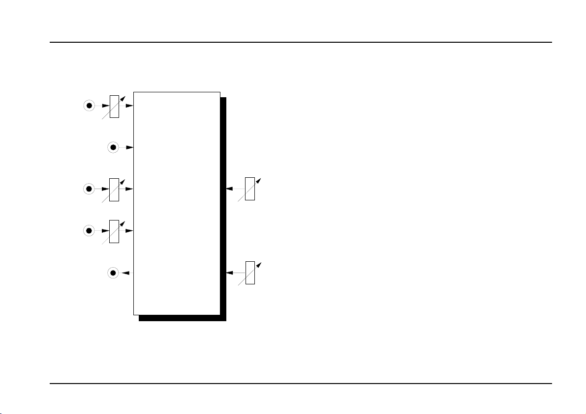
Level
FCV 2
QCV
Audio
In
FCV 1
FCV 2
QCV
Audio
Out
A-122
VCF 3
Frequency
Resonance
The modules A-105 and A-122 are voltage-
controlled low-pass filters, which filter out the higher
parts of the sound spectrum, and lets lower frequencies pass through.
The
cut-off frequency
filtering takes effect. You can control this manually, or
by voltage control (
an LFO). Two CV inputs are available. The cut-off
slope is
Voltage controlled resonance: for both A-105 and
A-122, resonance can be controlled not just manually,
but by voltages as well, right up to self-oscillation. In
this case, the filter behaves like a sine wave oscillator.
The A-105 is based on the special circuit SSM2044,
that was used in several devices of the companies
Korg (Polysix, Mono-Poly), Sequential Circuits
(Prophets, Pro-One), PPG, Fairlight, Emu and Kawai.
The circuitry of the A-122 uses a chip of Curtis Electromusic (CEM), and is very similar to the classic
Oberheim filter sound. Because of the different circuits the A-105 and A-122 have considerably different
sounds and even sound different compared to the
other filters (e.g. A-120 Moog low pass, A-102 Diode
Low Pass or A-103 18dB low pass, A-124 Wasp filter).
As the functions and controls are the same for both
modules they are a combined in one manual.
-24 dB/octave
determines the point at which
filter modulation
.
, for instance by
1
Page 2
A-105 / A-122 System A - 100
doepfer
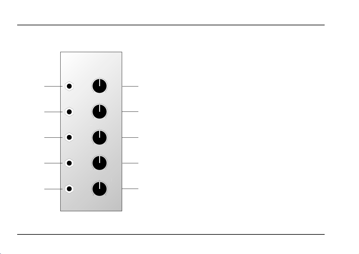
2. VCF 3 - Overview
A-122
24 dB Low Pass II
Audio In
0
FCV 1
0
FCV 2
0
QCV
0
Audio Out
0
VCF 3
Lev.
10
Frq.
10
FCV
10
QCV
10
Res.
10
➀
➁
➂
➃
➄
Controls:
: Attenuator for audio input
Lev.
1
Frq. : Cut-off frequency control
2
!
3 FCV : Attenuator for filter CV at input §
: Attenuator for resonance CV at input
QCV
4
$
5 Res.: Control for setting the filter’s reso-
nance (emphasis)
In / Outputs:
Audio In
!
FCV 1 : Input for voltage control of the filter
"
FCV 2 : ditto, level controlled by
§
$ QCV : Input for voltage control of the filter’s
Audio Out : Output from the filter
%
: Input to the filter
cut-off frequency (1 V /octave)
resonance; level controlled by
3
4
2
Page 3
doepfer
System A - 100 A-105 / A-122
3. Controls
1 Lev.
Use this attenuator to control the amount of signal
entering the filter input $.
H
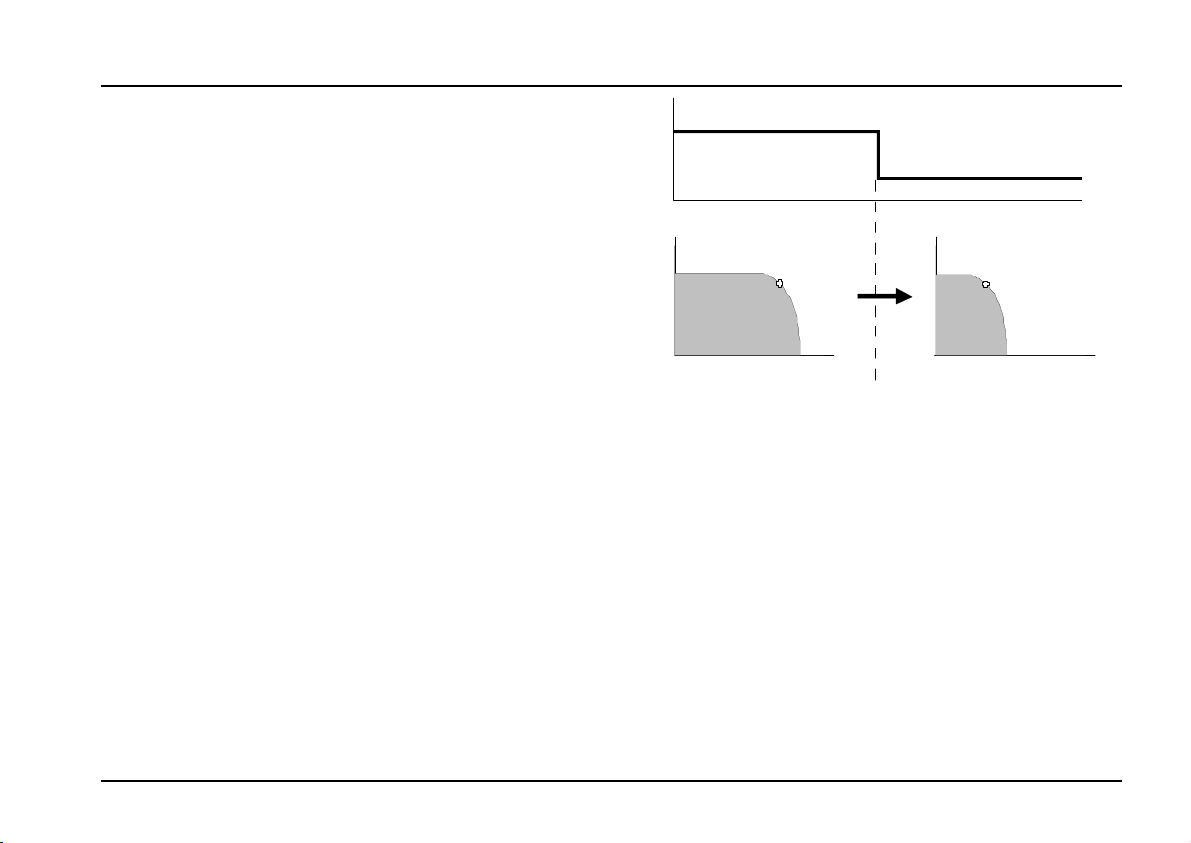
2 Freq.
With this control you adjust the Cut-Off Frequency fc,
above which the filter attenuates all frequencies. At 10,
the filter is fully open. The more you ‘close down’ the
filter, the more the high frequencies are filtered (see
Fig. 1): the sound becomes mellower and less bright,
until at 0 the filter is completely shut down, and there
will be no output signal at all.
3 FCV
For voltage control or modulation of the cut-off frequency using CV input § (see Fig. 1), use attenuator
to control the level of voltage control.
3
4 QCV
Attenuator 4 gives you control over the level of voltage control applied to resonance.
If the filter’s output sounds distorted, turn this
control down, unless you deliberately want
the sound as a special effect.
CV
Out Out
f
c
Fr e q. Fr e q.
Fig. 1: White noise put through a low pass filter
f
c
4 QCV
Attenuator 4 gives you control over the
tage control applied to resonance.
level of vol-
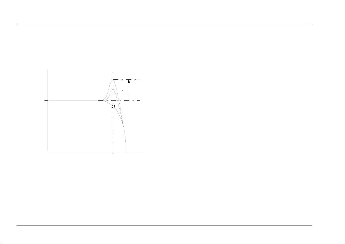
5 Res.
With this control you adjust the filter’s resonance (or
‘emphasis’) - the parameter which emphasises the
frequencies around the cut-off point f
strengthens or emphasises the band of frequencies
around the filter’s cut-off point.
(see Fig. 2). It
C
3
Page 4
A-105 / A-122 System A - 100
doepfer
At close to maximum resonance, the filter starts to
self-oscillate, and behaves like a sine wave oscilla-
tor. Thanks to this effect, you can use the filter as an
independent tone source.
am plitude
res onance
0 d b
fr equency
f
c
Fig. 2:
How resonance affects the behaviour of a
low pass filter.
4. In / Outputs
! Audio In
This is the filter’s
patch in the output from any sound source.
audio input
" FCV 1
Socket FCV 1 is a
It works on the 1V / octave rule, like the VCOs.
If you connect the output of a modulation source (eg
LFO, ADSR) to this input, the cut-off frequency of the
filter will be modulated by its voltage: ie, the sound
color changes according to the voltage put out by the
modulator.
P
If you use this VCF as a sine wave oscillator,
connect a pitch control voltage to this input.
Do the same if you want the filter’s cut-off
frequency to track exactly with the pitch of a
note.
voltage control input
§ FCV 2
Socket § is also a
Unlike on socket ", though, you can adjust the level of
voltage by using the attenuator 3 , and thus control the
intensity of modulation effect on the filter.
voltage-control input
socket, where you
for the filter.
for the filter.
4
Page 5

doepfer
System A - 100 A-105 / A-122
$ QCV
This socket is the voltage control input for the filter’s
resonance
If you patch a modulation source (eg LFO, ADSR) to
this input, the resonance of the filter will be modulated
by it: increases in voltage will increase the amplitude
of the frequencies around the filter cut-off point.
.
% Audio Out
Filter output % sends out the filtered audio signal.
5. User examples
The filter’s cut-off frequency can be modulated in
various ways:
• VCF - LFO
Modulation of the cut-off frequency produces cyclical changes of the sound spectrum. At low frequencies (c. 1 - 5 Hz), you get a
effect. Modulation in the audio range produces
interesting sounds; the same principles apply here
as with frequency modulation of the A-110 VCO
(see chapter 6).
• VCF - ADSR
Modulation by an envelope results in gradual
change of the sound spectrum. Typical uses
would be the
sounds, and filter sweeps, which slowly sweep
through the audio spectrum, emphasising different
harmonics.
• VCF - Keyboard CV
This modulation produces pitch-related filter opening: the higher the pitch, the more the filter opens,
and the brighter the sound becomes.
synthesis of electric bass or drum
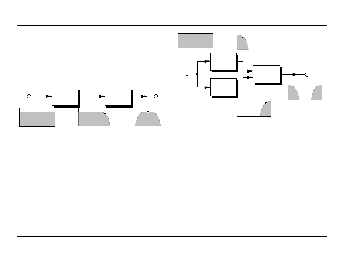
24 dB Bandpass • 24 dB Notch
By combining the A-123 high pass filter with the A-122
low pass filter, it’s possible to create 24 dB band
pass or 24 dB notch filters (as opposed to the
"Wah-Wah"
5
Page 6
A-105 / A-122 System A - 100
A-121 multi-mode filter’s 12 dB) with voltage control-
Fre q.
A-122
Ö
.
= (fL + fH ) / 2.
M
A-123
Fre q.
Ö
f
L
Fre q.
Ö
f
M
Fig. 4: 24 dB notch filter (resonance = 0)
led resonance
To create a bandpass filter, put both modules in
series (see Fig. 3). The band-width is governed by the
difference between the cut-off frequencies of the two
filters f
(A-122) and fH (A-123); the middle frequency
L
is half way between the two: f
Fre q.
Ö
A-122
A-123
f
L
Freq.
Fre q.
A-138
Ö
doepfer
Ö
Fre q.
Ö
f
M
f
H
Fig. 3: 24 dB band pass filter (resonance = 0)
A notch filter is created by putting both modules in
parallel
, and controlling their outputs with an A-138
mixer (see Fig. 4). The band-width and middle frequency are determined by the same factors as in the
bandpass.
When modulating these ‘construction kit’ filter types,
certain rules apply:-
6
• To maintain the exact bandwidth, the cut-off
frequencies of both filters must be modulated by
the same amount.
If you modulate the cut-off frequency of just one of
•
the filters, or both of them by different amounts, or
different modulators, the bandwidth and middle
frequency will themselves be modulated.
• At a resonance setting of greater than zero, or
when the resonance is modulated, the middle frequency will be skewed. With different resonance
settings or modulation of each filter, this will have
the same result.
Page 7

doepfer
Further examples can be found in the manual for the
A-123 high pass filter.
System A - 100 A-105 / A-122
7
Page 8

A-105 / A-122 System A - 100
6. Patch-Sheet
doepfer
The following diagrams of the module can help
you recall your own Patches. They’re designed so
that a complete 19” rack of modules will fit onto an
A4 sheet of paper.
Photocopy this page, and cut out the pictures of
this and your other modules. You can then stick
them onto another piece of paper, and create a
diagram of your own system.
Make multiple copies of your composite diagram,
and use them for remembering good patches and
set-ups.
P • Draw in patchleads with colored
pens.
• Draw or write control settings in the
little white circles.
A-122
24 dB Low Pass II
Audio In
FCV 1
FCV 2
QC V
Audio Out
VCF 3
Lev.
010
Fr q.
010
FCV
010
QCV
010
Re s .
10
0
A-122
24 dB Low Pass II
Audio In
FCV 1
FCV 2
QC V
Audio Out
VCF 3
Lev.
010
Fr q.
010
FCV
010
QCV
010
Re s .
10
0
A-122
24 dB Low Pass II
Audio In
FCV 1
FCV 2
QC V
Audio Out
VCF 3
Lev.
010
Fr q.
010
FCV
010
QCV
010
Re s .
10
0
8
 Loading...