

Page 1
doepfer
System A - 100
1. Introduction
VCF 2
A-121
Audio Level
FCV 2
QCV 2
Audio
FCV 1
FCV 2
QCV 1
QCV 2
A-121
In
MULTIMODE
FILTER
Freq.
Res.
Low Band High Notch
Module A-121 (VCF 2) is a voltage-controlled multimode filter with a cut-off slope of -12 dB / octave.
Four simultaneous outputs are available, each with
different characteristics: low-pass, band-pass, high-
pass and notch (or band reject).
The cut-off frequency determines the point at which
the respective filter effects appear. The frequency can
be adjusted manually, or by voltage control (Filter
modulation, for instance by an LFO or ADSR). Two
CV inputs are available, whose control voltages are
summed.
Resonance (Emphasis or Q ) can be adjusted
manually, or by voltage control (voltage-controlled
resonance / VCQ), right up to self-oscillation, in which
case it will behave like a sine wave oscillator.
1
Page 2
A-121
VCF 2
System A - 100
doepfer
2. VCF 2 - Overview
MULTIMODE FILTER
Audio In
➊
➋
➌
➍
➎
Notch
➏
High
➐
Band
➑
Low
➒
FCV 1
FCV 2
QCV 1
QCV 2
VCF 2
0
0
0
0
0
10
Freq.
10
FCV 2
10
10
QCV 2
10
Audio
Level
Res.
➀
➁
➂
➃
➄
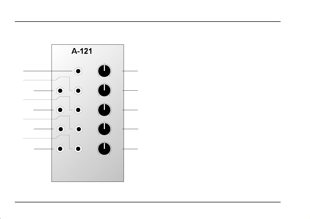
Controls:
1 Audio Level : Input signal attenuator
2 Freq. : Cut-off frequency control
3 FCV 2 : Attenuator for filter CV §
4 Res. : Resonance control
5 QCV 2 : Attenuator for resonance CV %
In / Outputs:
! Audio In : Audio input to the filter
" FCV 1 : Cut-off frequency CV input
§ FCV 2 : ditto, level controlled by 3
$ QCV 1 : Resonance CV input
% QCV 2 : ditto, level controlled by 5
& Low : Low-pass filter output
/ Band : Band-pass filter output
( High : High-pass filter output
) Notch : Notch filter output
2
Page 3
doepfer
System A - 100
VCF 2
A-121
3. Basics
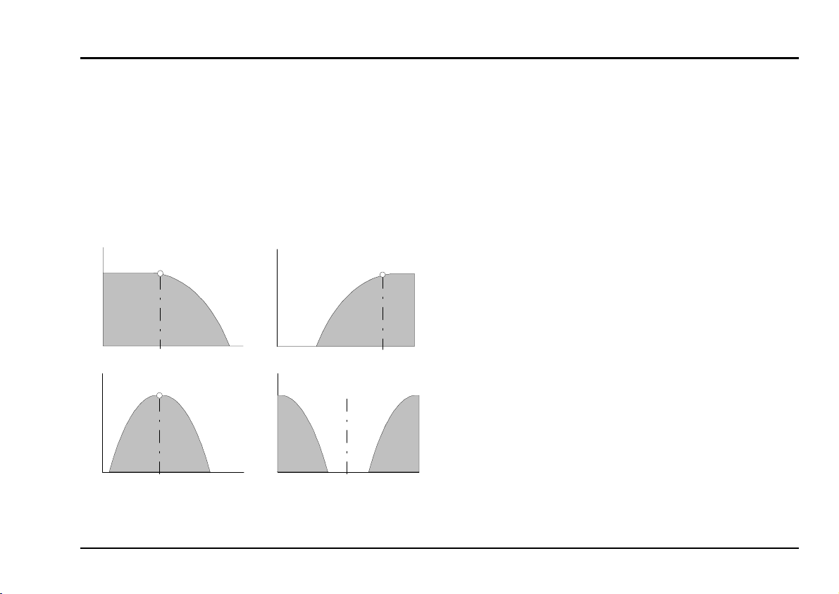
Low Pass
The most common type of filter in analogue sound
production is the low-pass, which filters out the higher
parts of the sound spectrum, and lets the lower fre-
High Pass
f
c
C
f
c
de-
Freq.
quencies pass unchanged. Cut-off frequency f
termines the frequency at which this occurs (see Fig.
1).
Out
Out
Low Pass
f
c
Band Pass Notch
f
c
Out
Freq.
Out
Freq. Freq.
High Pass
The high-pass filter is a precise mirror-image of the
low-pass filter: while it lets frequencies that are higher
than the cut-off frequency f
through, it attenuates
C
frequencies below the cut-off point (see Fig. 1).
Band Pass
In a band-pass filter, both ends of the frequency
spectrum are attenuated (see Fig. 1), and the cut-off
frequency f
becomes the mid frequency. It gives
C
you the ability to highlight a particular frequency band.
Notch
A notch filter is the opposite of a band-pass filter,
letting through the upper and lower end of the frequency spectrum, but rejecting a band in the middle
(see Fig. 1). If the mid-frequency f
LFO, the result sounds very similar to phasing.
is modulated by an
C
Fig. 1: Typical response curves of the four filters.
3
Page 4

A-121
Q
➨➨➨➨
VCF 2
System A - 100
doepfer
Resonance
Another filter parameter is resonance, also known as
emphasis or Q. As the value for Q gets higher, the
frequencies around the cut-off frequency f
phasised. Fig. 2 shows this process using a low-pass
filter as an example (a high-pass filter would produce a
mirror-image). This way, you can make the frequencies around the cut-off point stand out more.
0 db
Frequency
f
c
C
Res ona nce
are em-
In band-pass mode, an increase in Q’s value makes
the bandwidth narrower.
The same is true of notch mode, but of course in this
case this narrower band will be rejected, instead of let
through.
Setting the resonance close to maximum sends the
filter into self oscillation, and makes it behave like a
sine wave oscillator.
H
The A-121’s resonance is not frequency dependent to any significant degree. As long as
resonance is kept below the self-oscillation
level, any variation is imperceptible.
The one exception to this is at high levels of
resonance, coupled with a high cut-off frequency setting, when an increase in resonance can lead to a small drop in the sinewave output’s frequency. This is a characteristic of the CEM 3320 filter IC, and is not
due to a design fault in the A-121’s control
system.
Fig. 2: How resonance affects the response of a
filter around the cut-off frequency.
4
Page 5

doepfer
System A - 100
VCF 2
A-121
4. Controls
1 Audio Level
This attenuator controls the input level of the signal to
be filtered, entering the module at input ! .
H
2 Freq.
The filter frequency is adjusted with this control.
3 FCV 2
If you want to control or modulate the cut-off frequency
by a voltage patched into input §, use attenuator 3
FCV 2 to set the level of voltage control.
4 Res.
With this control you adjust the resonance of the filter,
which emphasises the frequencies around the cut-off
frequency f
If the filter’s output signal is distorted, turn
this control down, unless the distortion is
wanted as a special effect.
.
C
Close to the maximum position, the filter goes into
self-oscillation. In this mode it behaves like a sine
wave oscillator, and can be used as an alternative
sound source.
5 QCV 2
Attenuator 5 lets you control the level of voltage
control signal modulating the resonance (Q).
5
Page 6

A-121
VCF 2
System A - 100
doepfer
5. In / Outputs
! Audio In
This socket is the filter’s audio input. Patch the
output of a sound source (such as a VCO, noise
generator or mixer) into it.
" FCV 1
Socket FCV 1 is a voltage control input for the filter
frequency. It works to the 1 V / octave standard (like
a VCO).
If you patch a modulation source (eg LFO, ADSR) to
this input, the cut-off frequency of the filter will be
modulated by its voltage: ie., the sound color changes
according to the voltage put out by the modulator.
If you use the VCF as a sine wave oscillator, connect
the pitch CV into this socket. Do the same if you want
the filter’s cut-off frequency to track exactly with the
pitch of a note.
§ FCV 2
Socket FCV 2 is another voltage control input for
the filter. Unlike CV 1, you can control the level of
voltage - the intensity of the modulation effect on the
filter - with attenuator 3.
$ QCV 1
This socket is the voltage control input for the filter’s
resonance. It works to the 1 V / octave standard (like
a VCO).
If you patch a modulation source (eg LFO, ADSR) to
this input, the resonance of the filter will be modulated
by its voltage: ie., the sound color of the frequencies
around the cut-off point changes according to the
voltage put out by the modulator.
% QCV 2
This is another voltage control input for controlling
the resonance, but unlike QCV1 it gives you the ability
to use Attenuator 5 to control the amount of voltage
control, and therefore the intensity of its effect on the
filter’s resonance.
& Notch • / High • ( Band • ) Low
Sockets & to ) are the filter outputs. They simultaneously carry the input signal modified by the
respective filter types (see Fig.1).
6
Page 7

doepfer
System A - 100
VCF 2
A-121
6. User examples
The A-121’s cut-off frequency can be modulated in a
variety of ways:
• VCF - LFO
Modulation of the cut-off frequency produces cyclical changes of the sound spectrum. At low frequencies (c. 1 - 5 Hz), you get a "Wah-Wah"-
effect. Modulation in the audio range produces
interesting sounds; the same principles apply here
as with frequency modulation of the A-110 VCO
(see chapter 6).
• VCF - ADSR
Modulation by an envelope results in gradual
change of the sound spectrum. Typical uses
would be the synthesis of electric bass or drum
sounds, and filter sweeps, which slowly sweep
through the audio spectrum, emphasising different
harmonics.
• VCF - Keyboard CV
This modulation produces pitch-related filter opening and closing.
Spatial manipulation of the spectrum
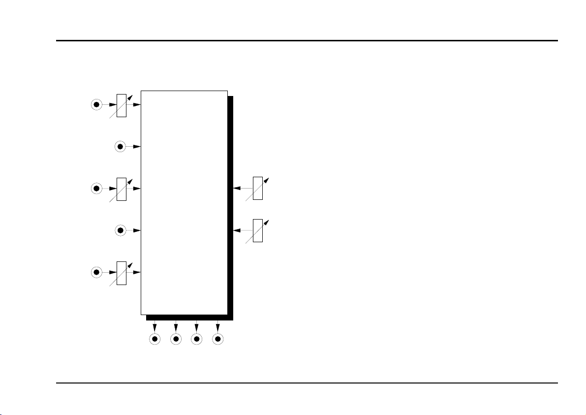
Fig. 3 shows an interesting application of the multimode filter. Each of the four outputs is fed to one
corner of a quadraphonic sound stage (VCAs and
amplifiers, etc. have been omitted for the sake of
clarity).
Each channel sends out only a part of the audio
spectrum, depending on its respective filter’s frequency response, and the result is interesting spatial
distribution of the different spectral elements of the
sound.
Audi o Level
Audio
In
A-121
MULTIMODE
FILTE R
Input
FCV 2
QCV 2
FCV 1
FCV 2
QCV 1
QCV 2
Low Band High Notch
Freq.
Res.
Quad Space
Fig. 3: spatial manipulation of the spectrum
7
Page 8

A-121
VCF 2
System A - 100
Generating vocal effects
With the patch in Fig. 4 (see next page) vocal effects
can be produced, using two A-121 filters.
A sawtooth at around 100 Hz or less is patched into
two A-121 filters. Set Q to a small or medium level,
and use different mid-frequencies for each of the two
filters.
Modulate the VCO and both filters with a triangle wave
LFO at about 1 Hz, but with the voltage input to one of
the filters inverted by an A-175 inverter. Set the
modulation amount for the VCO (Attenuator CV3) and
for the filter (Attenuator FCV2) to a small or medium
value.
You can control the intensity of the modulation with a
dynamic MIDI controller - aftertouch, mod wheel, etc..
Experiment a little with this patch (see next page). W ith
careful setting up and tweaking, interesting vocal-like
timbres can be produced.
doepfer
8
Page 9

doepfer
System A - 100
VCF 2
A-121
CV
VCO
Gate
LFO
CV 2
A-132
CV 3
A-175
Controller CV
Fig. 4: Producing vocal-like sounds
P
Check out various different combinations of
mid-frequency settings on the filters.
Experiment with different envelope settings.
A-121
A-121
Band
Band
P
A-138
A-131
ADSR
By turning down the pitch CV input to the
VCO, more speech-like intonation can be
achieved.
Patch a Slew Limiter (A-170) in before the
VCO’s CV input, so that the ‘voice’ intonation
slides, rather than jumping in discrete steps.
9
Page 10
A-121
VCF 2
7. Patch-Sheet
System A - 100
doepfer
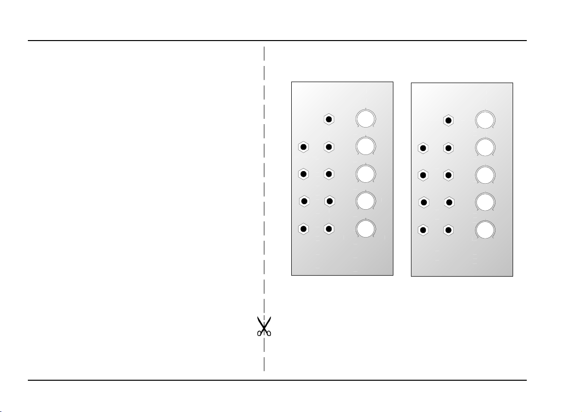
The following diagrams of the module can help you
recall your own Patches. They’re designed so that
a complete 19” rack of modules will fit onto an A4
sheet of paper.
Photocopy this page, and cut out the pictures of
this and your other modules. You can then stick
them onto another piece of paper, and create a
diagram of your own system.
Make multiple copies of your composite diagram,
and use them for remembering good patches and
set-ups.
P
• Draw in patchleads with colored
pens.
• Draw or write control settings in the
little white circles.
A-121
MULTIMODE FILTER
Audio In
FCV 1
Notch
FCV 2
High
QCV 1
Band
QCV 2
Low
0
0
0
0
0
VCF 2
Audio
Level
10
Freq.
10
FCV 2
10
Res.
10
QCV 2
10
A-121
MULTIMODE FILTER
Audio In
FCV 1
Notch
FCV 2
High
QCV 1
Band
QCV 2
Low
0
0
0
0
0
VCF 2
Audio
Level
10
Freq.
10
FCV 2
10
Res.
10
QCV 2
10
10
 Loading...