

Page 1
doepfer
Asym.
In
A-119
Ext. In.
System A - 100
1. Introduction
Module A-119 (External Input / Envelope Follower)
is designed to allow external audio signals to be
integrated into the System A-100. It comprises a pre-
amp, envelope follower, and comparator.
Ext. Input / Envelope Follower
A-119
Symm. In
Audio
Out
Envelope
Out
Gate
Out
Gain
OverLoad
Threshold
The pre-amp has two inputs: an unbalanced input for
line level signals, with a gain factor of from 0 to 20, and
a balanced input with a gain factor of from 0 to 500,
for insertion of low level signals, for instance from a
microphone or electric guitar.
The Envelope Follower reads the signal level of the
input, and puts out a proportional voltage as an envelope at its own output (see chapter 3. How it works).
The comparator generates a gate signal whenever the
input goes above an adjustable trigger threshold (see
chapter 3. How it works).
Three LEDs help you keep track of overload, the
envelope, and the gate signal.
1
Page 2
A-119
Ext. Input / Envelope Follower
System A - 100
doepfer
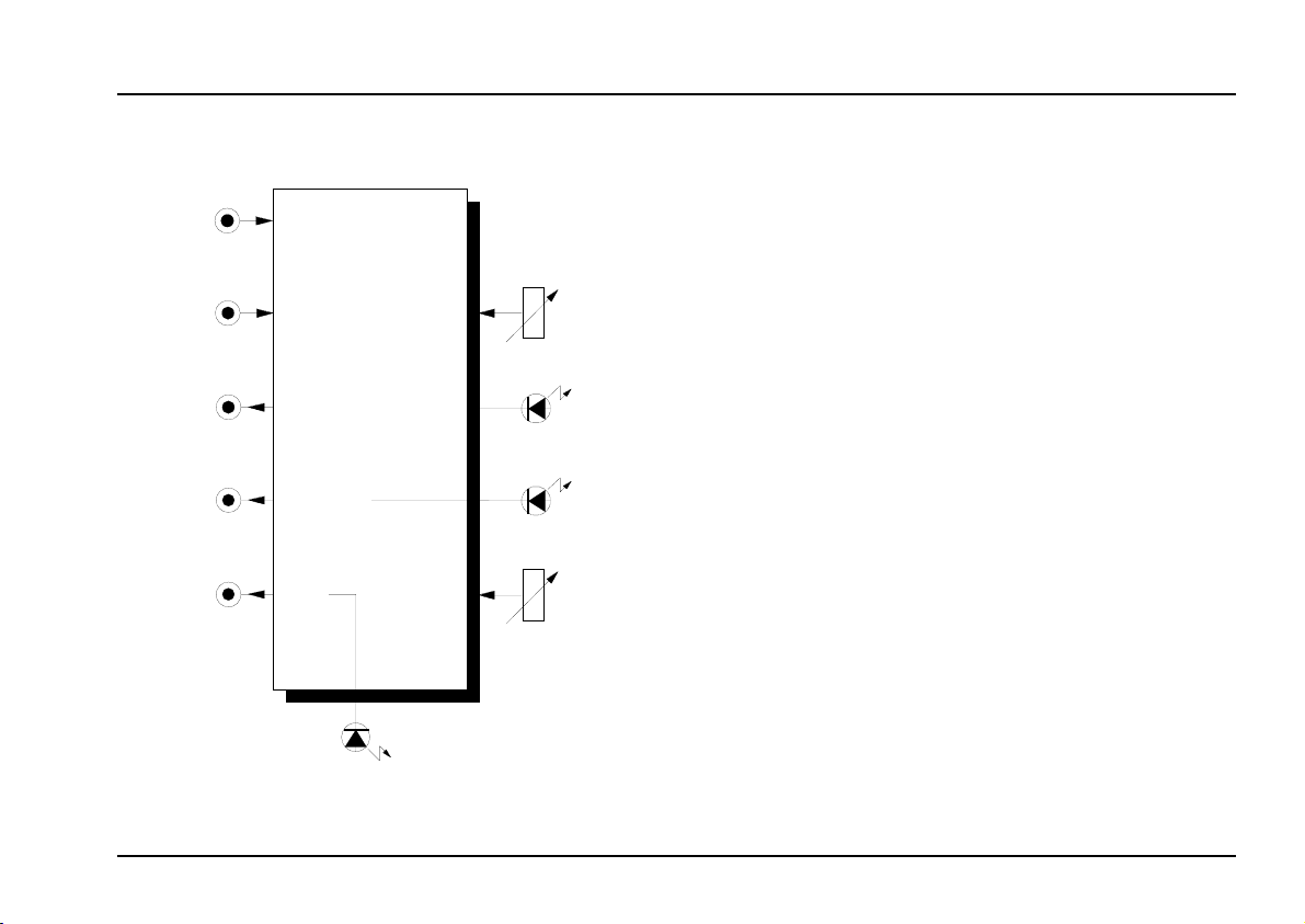
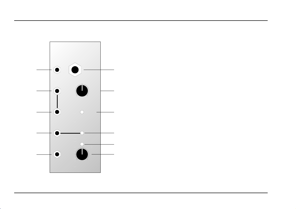
2. A-119 - Overview
A-119
Ext. Input / Env. Follower
Asym. In
➊
Audio Out
➌
➍
Envelope
Out
➎
Gate Out
➏
Ext. In.
0
0
Symm.
In
10
OverLoad
Thres.
10
Gain
➋
➀
➁
➂
➃
➄
Controls and indicators:
1
Over-Load : LED overload warning
2
3 LED : Envelope level indicator at (output %)
4
Thres. : Trigger threshold control
5
: Control for input signal level
Gain
: Gate indicator (output &)
LED
In / Outputs:
! Asym. In : Unbalanced input for line-level audio
Symm. In
"
Audio Out
§
Audio Out : ditto, linked with output
$
% Env. Out : Envelope output
Gate Out
&
: Balanced input for mic or instrument-
level signals (6.3 mm jack socket)
: Output for pre-amped audio signal
§
: Gate output
2
Page 3
doepfer
System A - 100
Ext. Input / Envelope Follower
A-119
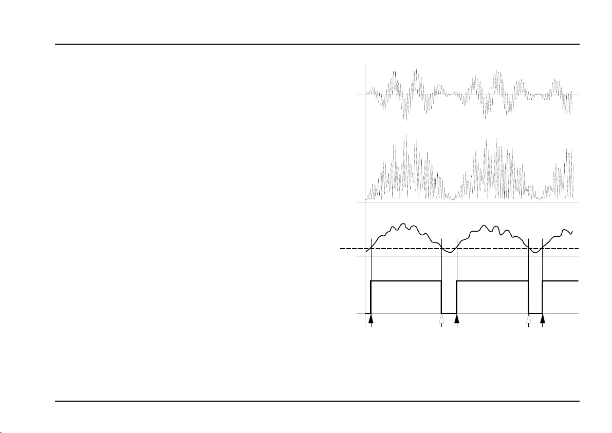
3. The Envelope Follower: how it works
The external audio signal (see Fig. 1a) is patched into
input ! or ", depending on its level. It is amplified by
an amount set by the gain control 1, brought up to
A-100 internal operating level, and can then be output
from audio outs § and/or $.
To produce envelope and gate signals, the amplified
signal is put through a full-wave rectifier, so that the
internal signal output has only positive voltages (see
Fig. 1b).
Next, the rectified signal passes through a 50 Hz low
pass filter, and is sent to envelope output %.
H With input frequencies of less than 50 Hz,
patch the envelope output % into an A-170
slew limiter, set to a time constant of greater
than 20 ms, to avoid remnants of the signal
being audible in the envelope.
The signal at the envelope output is compared with the adjustable trigger threshold (T in
Fig. 1c), to produce gate signals, available at
output &.
a
0
b
0
c
T
0
d
0
: The envelope follower: how it works
Fig. 1
3
Page 4

A-119
Ext. Input / Envelope Follower
System A - 100
doepfer
As soon as the envelope amplitude exceeds the trigger threshold T, the gate signal is output (see the black
arrows in Fig. 1d on the previous page). When the
signal drops below the threshold again, the gate signal
stops (see the white arrows in Fig. 1d).
4. Controls and indicators
1 Gain
This knob controls the amount of amplification the
external signal receives. This depends on the input
chosen:
unbalanced input ! : 0 ... 20
•
balanced input " : 0 ... 500.
•
Overload
2
LED 2 lights when the circuit is overloaded - that is,
when the amplified signal exceeds 10 V.
3 LED
The voltage of the envelope produced at output
can be monitored with LED 3.
4 LED
LED
monitors the
4
gate signal
at output &.
5 Threshold
Control 5 is used to set the trigger threshold T,
above which a gate signal is generated (see Fig. 1c).
5. In / Outputs
! Asym. In
The 3.5 mm mono mini-jack socket ! is the A-119’s
unbalanced input, designed predominantly for line
level external audio signals and/or audio generated
within the A-100 system.
" Symm. In
The 6.3 mm stereo full-size jack socket " is the
A-119’s balanced input, for low level signals such as
from a microphone, electric guitar, and so on.
%
H Because there’s just one gain control for two
inputs, only use one input at a time. If you
use both at once, their signals will be mixed
in a 1:25 ratio.
4
Page 5

doepfer
System A - 100
Ext. Input / Envelope Follower
A-119
§ Audio Out • $ Audio Out
The external audio signal,
amplified
by the gain control, is available at audio output
and/or $. These two sockets are simply linked as a
“mini-multiple”.
by an amount set
% Env. Out
The envelope generated by the A-119 is available at
this output % (see Fig. 1c).
Gate Out
&
The gate signal generated by the A-119 is available at
this output (see Fig. 1d).
6. User examples
§
Manipulating external audio signals
The A-119 is what makes it possible for individual
parts of the A-100 to manipulate external signals. In
the patch in Fig. 2, an external audio signal is filtered
by a VCF, whose cut-off frequency is controlled by an
ADSR.
ext.
Audio
Asym.
In
Symm. In
Audio
Out
Envelope
Out
Gate
Out
A-119
Ext. In.
Threshold
Gain
OverLoad
ADSR
VCF
VCA
: Filtering an external audio signal
Fig. 2
5
Page 6

A-119
Ext. Input / Envelope Follower
System A - 100
doepfer
Ring modulator squelch patch
A ring modulator works particularly well with
audio signals such as voices, strings, or saxophone.
In the patch in Fig. 3 a typical external audio signal is
ring modulated with a sine wave.
A-114
RING MOD.
ext.
Audio
VCO
Asym.
In
Symm. In
Audio
Out
Envelope
Out
Gate
Out
A-119
Ext. In.
Threshold
Gain
OverLoad
X IN
Y IN
X • Y OUT
Fig. 3: Ring modulator squelch patch
external
VCA
Gain = 0
A-170
to generate an envelope which can then control the
ring modulator’s output via a VCA.
This is necessary because the ring modulator doesn’t
shut down completely when there’s a 0 V input. It
goes to about -50 or -60 dB, and so traces of the VCO
or external signal can still be heard.
The combination of the A-119 and VCA causes the
ring modulator to shut down completely (‘squelch’) if
there is no input present.
The A-170 slew limiter smooths out the gate signal
generated by the A-119 a little, to avoid clicks in the
VCA.
P Instead of gate signals, you can use the
envelope generated by the A-119 to control
the VCA, and thus maintain the loudness
pattern of the original sound.
In this patch, the A-119 has two functions. One is to
bring the level of the signal output at § and/or $ up to
the operating level of the A-100 (c. 5 V). The other is
6
Page 7

doepfer
System A - 100
Ext. Input / Envelope Follower
A-119
“Ducking”, using an external signal
In the patch in Fig. 4 the amplitude of an external audio
signal controls the loudness of an A-100 patch.
Whenever an external audio signal is present, the
internal A-100 sound is attenuated (set the gain of
VCA 2 high).
Without the A-175 inverter, the opposite of this occurs
(set the gain of VCA 2 to zero).
0
Gate
ext.
Audio
CV
VCO
ADSR
Asym.
In
Symm. In
Audio
Out
Envelope
Out
Gate
Out
A-119
Ext. In.
Threshol d
Gain
OverLoad
VCA 1
VCA 2
Gain = 10
A-175
0
"Singing synth"
With the patch in Fig. 5, you can create a ‘singing
synth’: when you sing into the microphone, out of the
VCA comes a very interesting sound, distinctive but
difficult to describe. Turn up the first and second
sub-octaves on the A-115, and turn the original ound
right down
Micro
.
A-115
ADSR
Asym.
In
Symm. In
Audio
Out
Envelope
Out
Gate
Out
A-119
Ext. In.
Threshold
Gain
OverLoad
A-120
VCA
Fig. 4: “
Fig. 5: "Singing synth"
Ducking” by using an external signal
7
Page 8

A-119
Ext. Input / Envelope Follower
System A - 100
doepfer
8
 Loading...