

Page 1
doepfer
System A - 100
1. Introduction
DIVIDER A-115
Audio In
A-115
DIV IDER
Audio
Out
Orig .
F / 2
F / 4
F / 8
F / 16
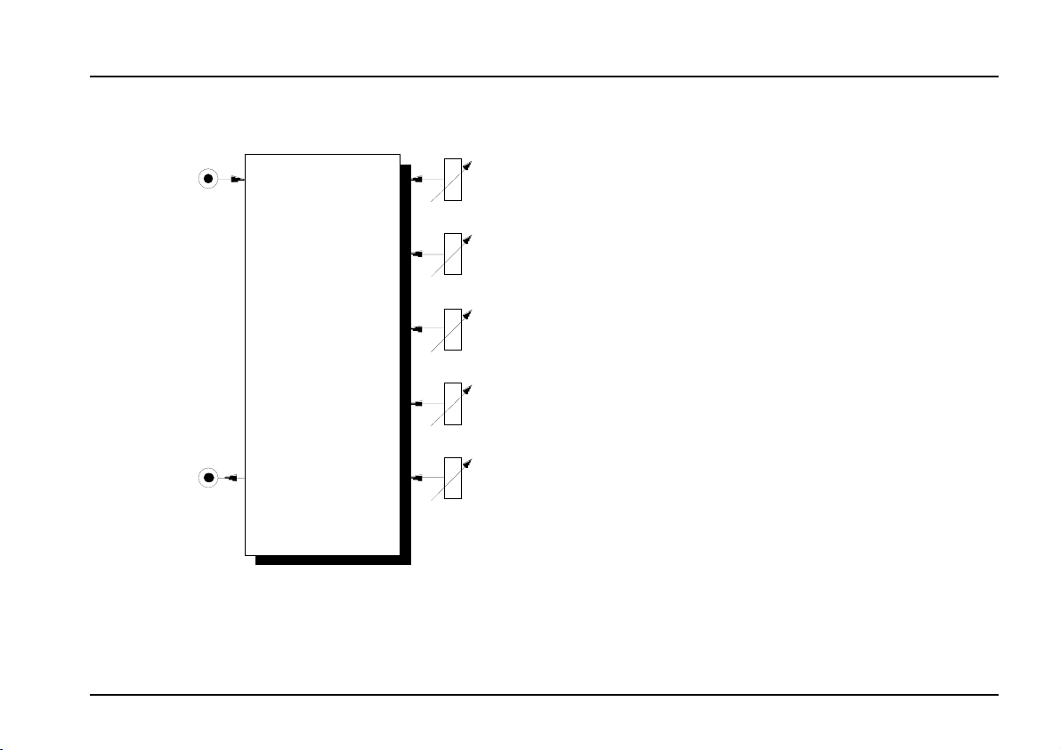
Module A-115 (DIVIDER) is a four-way frequency
divider
The frequency of a signal at the input is halved (half
frequency = first sub-octave), quartered (1/4 frequency
= second sub-octave), and so on.
In this way, the DIVIDER produces four sub-octaves
(F/2 down to F/16).
At the output, the A-115 produces a summed mix of
the original and the four sub-octaves. There are attenuators to control the amount (ie. Amplitude) of the
original signal and each of the sub-octaves.
Bear in mind that the sub-octaves output by the A-115
are all true square waves. If you put, eg., a sawtooth
into the Divider, it changes it into a square wave before
the frequency division takes place (using the SchmittTrigger system, if you’re interested). At the output,
therefore, there are always four square waves and the
original signal available.
.
1
Page 2
A-115
DIVIDER
System A - 100
doepfer
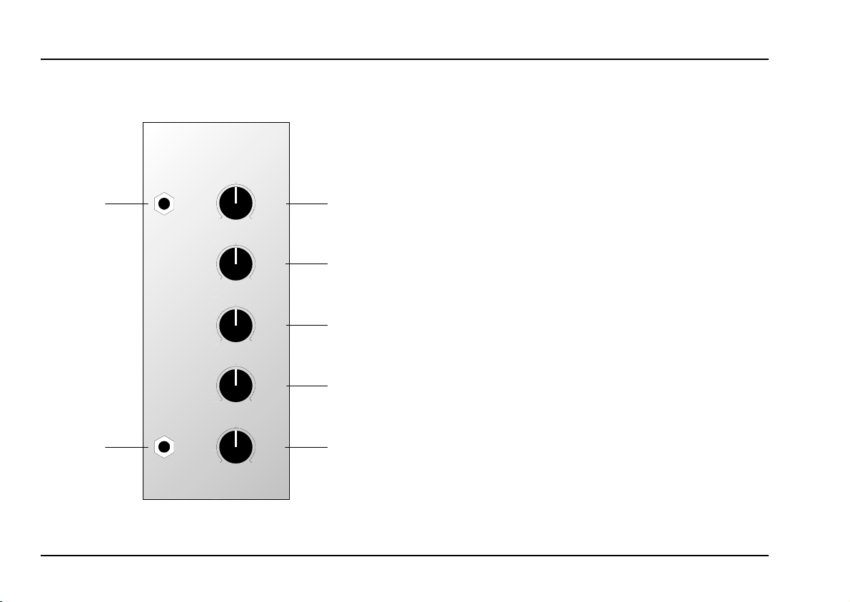
2. DIVIDER - Overview
A-115
In
➊
Out
➋
DIVIDER
0
0
0
0
0
10
10
10
10
10
Orig.
F / 2
F / 4
F / 8
F / 16
➀
➁
➂
➃
➄
Controls:
: Attenuator controlling the amount of
Orig.
1
the original input signal present at the
mix output "
: Attenuator controlling the amount of
F / 2
2
the first sub-octave present at the mix
output
F / 4 : ditto for the second sub-octave
3
4 F / 8 : ditto for the third sub-octave
5 F / 16
: ditto for the fourth sub-octave
"
In / Outputs:
In : Signal input
!
Out : Mix signal output
"
2
Page 3

doepfer
System A - 100
DIVIDER A-115
3. Controls
1 Orig.
This attenuator controls the amount of the original
input signal present in the mix output.
2 F / 2 ... 5 F / 16
These attenuators 2 to 5 control the amount of the
respective sub-octaves present in the mix output.
Say your production needs a stronger bass-line: you
can add a square wave an octave below the original
signal simply by setting attenuators 1 and 2 to maximum, and attenuators 3 to 5 to 0.
4. In / Outputs
! Audio In
Socket ! is the divider’s
whose frequency you wish to divide.
The divider is basically set up to divide rectangle
H
waveforms. If you put another waveform into the
input (for instance a sawtooth) the A-115 will
change it into a square wave before dividing it.
" Audio Out
At
output
sub-octaves (depending on the position of attenuators
1 to 5) is available.
" the total mix of the original signal and four
. Connect up the signal
input
5. User examples
A-115 as a "frequency generator"
With the A-115, you can start out with a VCO’s basic
square wave and produce more complex waveforms.
Fig. 1 shows how the A-115 can take a simple square
wave and create a new wave form. Turn attenuators
to 4 up to maximum, and set attenuator 5 to 0.
1
Audio In
VCO
: The A-115 as a frequency generator
Fig. 1
A-115
DIVIDER
Audio
Out
Experiment with different level settings for each attenuator, and also with other waveforms (for instance,
a square wave modulated by a slow LFO).
In
F / 2
F / 4
F / 8
3
Page 4

A-115
DIVIDER
System A - 100
doepfer
Frequency division of external audio
The patch in Fig. 2 shows how the A-115 can
frequency-divide an external monophonic signal (such
as a vocal, flute, or single-note guitar).
A-120
Audio Out
Audio In
A-115
DIVIDER
A-119
ext.
Audio In
Env. Out
Audio
Out
ADSR
Fig. 2: Frequency division of external audio
The A-119 again has a double task: to bring the
external signal up to the level the A-100 needs, so that
the divider works properly, and to send voltages to an
ADSR. That means that the Threshold control must
be set relatively high, so that when the signal isn’t
In
F / 2
F / 4
F / 8
F / 16
VCA
gated, there’s enough level for the divider to work
correctly.
The ADSR controls a VCA, and closes it as soon as
the gate shuts down, so that possible glitches (eg.
when the sound of a string is dying away), are
avoided.
H The ADSR’s release parameter must be set
to Zero.
If you like, you can patch an A-120 low pass filter (not
voltage controlled) in before the A-115. This may
improve the frequency division.
4
Page 5

doepfer
System A - 100
DIVIDER A-115
5
Page 6

A-115
DIVIDER
6. Patch-Sheet
System A - 100
doepfer
The following diagrams of the module can help
you recall your own Patches. They’re designed so
that a complete 19” rack of modules will fit onto an
A4 sheet of paper.
Photocopy this page, and cut out the pictures of
this and your other modules. You can then stick
them onto another piece of paper, and create a
diagram of your own system.
Make multiple copies of your composite diagram,
and use them for remembering good patches and
set-ups.
P • Draw in patchleads with colored
pens.
• Draw or write control settings in the
little white circles.
A-115
In
Out
DIVIDER
10
0
10
0
10
0
10
0
F / 16
10
0
Orig.
F / 2
F / 4
F / 8
A-115
In
Out
DIVIDER
10
0
10
0
10
0
10
0
F / 16
10
0
Orig.
F / 2
F / 4
F / 8
A-115
In
Out
DIVIDER
10
0
10
0
10
0
10
0
10
0
Orig.
F / 2
F / 4
F / 8
F / 16
6
 Loading...