

Page 1
doepfer
CV 2
CV 1
A-111
High End VCO
CV 2
Range
System A - 100
1. Introduction
Module A-111 (VCO 2) is a voltage controlled oscil-
.
lator
The VCO has a range of about 12 octaves, and
produces four waveforms simultaneously: pulse
(rectangle), sawtooth, triangle and sine waves.
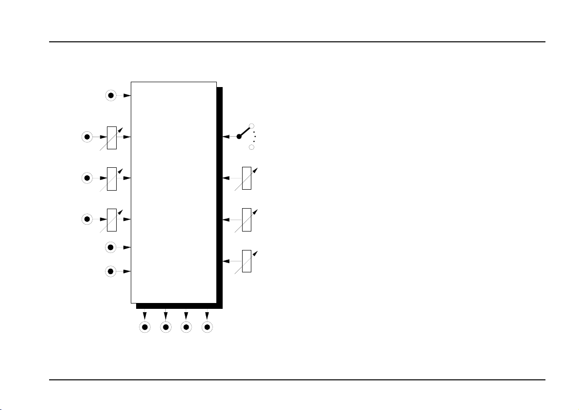
VCO 2 A-111
Lin. FM
PCV
Lin. FM
PCV
H-Sync
S-Sync
Saw Sine Tri Puls e
Tune
Fine
PW
The VCO's frequency is determined by the position of
the range switch, tune and fine tune controls, and the
voltage at the two pitch CV inputs, CV 1 and CV 2.
Footage
(the octave of the fundamental) is set by the
Range control, which has seven octave steps. The
Tune control is used for coarse tuning, and the Fine
control for
fine tuning
of the VCO pitch.
The A-111 can be modulated by both exponential and
linear FM (frequency modulation).
You can control the
pulse width
of the square wave
either by hand, or by voltage control - Pulse Width
Modulation, or PWM for short.
The A-111 has inputs for Hard Sync and Soft Sync.
1
Page 2
A-111
VCO 2
System A - 100
doepfer
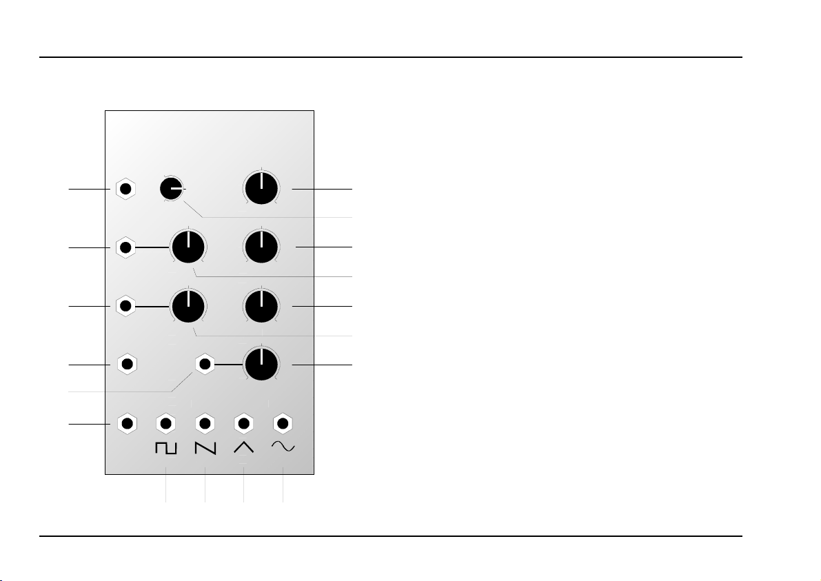
2. VCO 2 - Overview
A-111
HIGH END VOLTAGE CONTR. OSCILLATOR
➊
➋
➌
➍
➏
➎
CV 1
CV 2
Lin. FM
H-Sync PCV
S-Sync Pulse Saw Triangle Sine
-3
Octave
0
+4
CV 2
10
0
Lin. FM
10
0
VCO 2
0
0
0
0
Tune
10
10
10
10
Fine
PW
PCV
➁
➀
➂
➃
➄
➆
➅
Controls:
Range
1
Tune : Control for coarse tuning
2
3 Fine : Control for fine tuning
CV 2
4
PW : Manual control for pulse width
5
PCV
6
Lin. FM : Attenuator for voltage at linear FM
7
: 7-position switch for octave selection
: Attenuator for pitch CV at input
"
: Attenuator for PWM voltage at PCV
input §
In- / Outputs:
! CV 1 : Pitch control input (1 V/oct.)
"
Lin. FM : CV input for linear FM
§
$ H-Sync : Input for hard synchronisation
%
PCV : Input for pulse width modulation CV
&
/, (, ), = : VCO outputs
: ditto, level adjustable with
CV 2
S-Sync
: Input for soft synchronisation
4
&
➐
➑➒➓
2
Page 3
doepfer
System A - 100
VCO 2 A-111
3. Basics
3.1 Waveforms
Module A-111 puts out four waveforms simultaneously. All these signals have the same pitch, since
all are controlled by the same CVs at inputs ! and " .
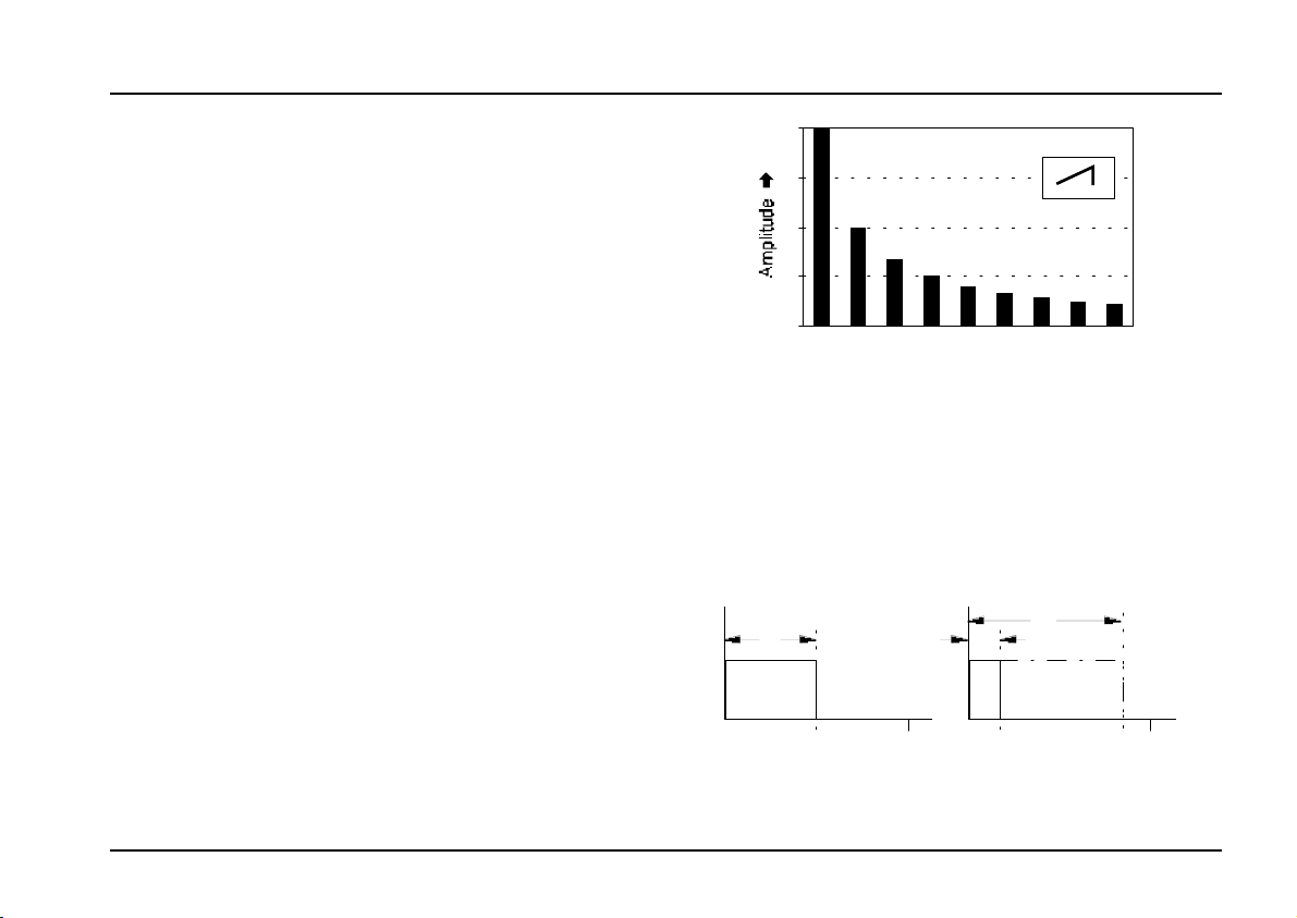
Sawtooth
The VCO’s sawtooth waveform is available at output
/. It has a ‘cutting’ sound, rich in overtones. All the
harmonics of the fundamental are present, with a
linear reduction in intensity as the harmonic series
progresses - so that the second harmonic is half as
strong, the third is one third, the fourth a quarter, etc.
(see Fig. 1).
Sawtooth waves are ideal for synthesizing sounds
which are rich in harmonics, such as percussion, brass
or vocal timbres, and as the carrier input to a vocoder.
Pulse wave
The VCO produces a square / rectangle wave at
output =. You can alter its pulse width (see Fig. 2) by
hand or by voltage control (
or PWM for short).
pulse width modulation
100 %
0%
f1f
f3f4f
2
f6f7f8ff
5
Harmo n ics
9
➨
Fig. 1: Harmonic spectrum of a sawtooth
A symmetrical pulse wave (ie. an exact square
wave, with a pulse width of 50%) has only odd harmonics of its fundamental (see Fig. 3) and produces a
typically hollow sound.
c
a
1/f 1/f
b
Fig. 2: Rectangle waves with different pulse widths
3
Page 4
A-111
VCO 2
System A - 100
doepfer
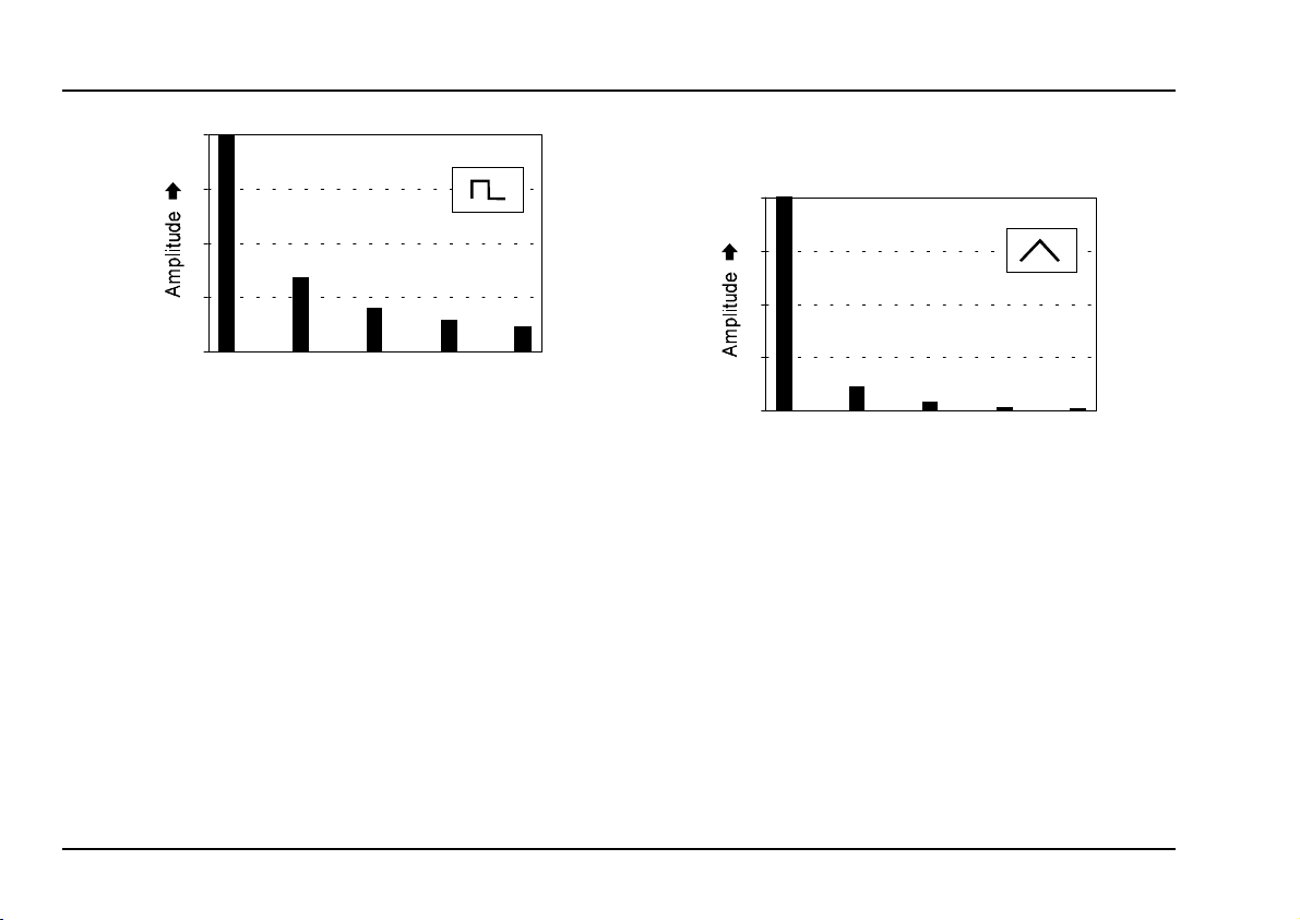
100%
0%
f1f
2
f3f4f
f
6
5
Harmonics
f7f8ff
9
➨
Fig. 3: Harmonic spectrum of a true square wave
The further the pulse width deviates from 50% (see
Fig. 2, b and c), the weaker the lower harmonics
become, and the more the sound gets thin and nasal.
Pulse waves are often used as a sound source in
subtractive (filtered) synthesis, because of their rich
overtones, and are good at producing woodwind-like
timbres.
Triangle wave
A triangle wave (output )) is poor in upper harmonics,
and sounds softer and more mellow. It only contains
odd harmonics, whose strength decreases exponenti-
ally - the third harmonic is a ninth as strong, the fifth
1/25, and so on.
100%
0%
f1f
2
f3f4f
f
6
5
Harmonics
f7f8ff
9
➨
Fig. 4: Harmonic spectrum of a triangle wave
Because of their soft, rounded timbre, triangle waves
are ideal for synthesizing timbres like flute, organ and
vibes. Because of the comparative weakness of the
upper harmonics, they are not ideal for treating with a
low pass filter, in subtractive synthesis.
4
Page 5
doepfer
System A - 100
VCO 2 A-111
Sine wave
Sine waves are pure waves: they just contain the
fundamental, without any harmonics (see Fig. 5).
They are thus not suitable for subtractive synthesis
(shaping sound with a filter) - as there’s nothing to take
away!
100%
0%
f1f
2
f3f4f
f
f7f8ff
6
5
Harmonics
9
➨
Fig. 5: Spectrum of a sine wave
3.2 Frequency Modulation (FM)
Since the frequency of the VCOs can be voltage
controlled, that of course makes frequency modula-
tion (FM) possible. The frequency changes conti-
nuously, depending on the incoming voltages at CV1
and CV2. In contrast with the standard VCO module
(A-110), the A-111 provides two types of frequency
modulation.
For
exponential FM
(like on the A-110) you simply
input a modulation signal via the normal CV inputs, !
or ". For linear FM there is a dedicated CV input §,
complete with attenuator.
If the modulation signal is in the sub-audio range (for
instance modulation with a slow LFO), there’ll be no
real difference noticeable between the two types. The
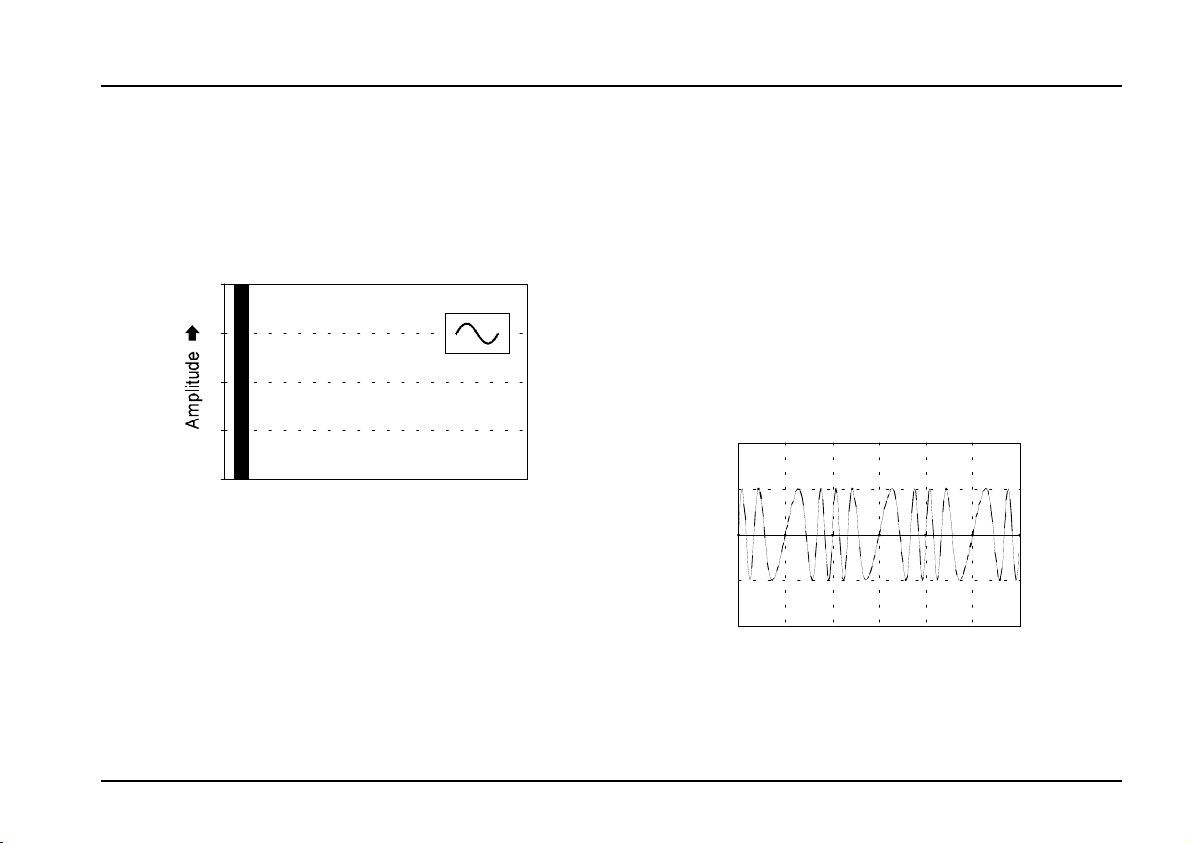
result in both cases is a typical vibrato (see Fig. 6).
Fig. 6: Frequency modulation with a slow LFO
(vibrato)
5
Page 6

A-111
VCO 2
System A - 100
doepfer
Completely different sounds will emerge, though, if the
modulation frequency is in the audio range.
Exponential FM in the audio range
For exponential FM, patch the modulation voltages
into CV input ! or " (see Fig. 7).
CV 1
A-110
VCO
Range
Tune
CV 2
CV 2
A-110
VCO
Range
Tune
Fig. 7: Frequency modulation in the audio range
Thanks to the rapid changes in the modulated VCO’s
pitch, side bands are created: as well as the two
original frequencies, you also get the frequencies created by their sum and difference (for instance a modulation frequency of 100 Hz and a carrier frequency of
500 Hz produce side bands at 400 Hz and 600 Hz).
When you try this out for the first time, start off with
sine waves, and slowly raise the modulation frequency
from the sub-audio into the audio range.
If you use waveforms other than sine waves in FM in
the audio range, the sounds that result will be extremely complex and difficult to predict. A sawtooth, for
instance, is like a vast number of sine waves of
different frequencies - all of which will be represented
in the modulated output, so that the final sound will be
a complex mix of the buzzes, noises and tones produced by all the various sum and difference outputs.
With exponential FM, changes in control voltage pro-
duce
proportional changes in the pitch relationship
of the component sounds. This can have unwanted
side-effects. If a 440 Hz VCO sine wave is modulated
by a 2 V
amplitude sine wave ( see Fig. 8), the top
SS
and bottom side-bands are respectively up and down
one octave, at 880 Hz and 220 Hz. You might think
that would be fine - but with modulation in the audio
range, we hear the note half-way between these frequencies - 550Hz - and this is (not surprisingly) out of
tune with the original 440 Hz carrier note.
6
Page 7

doepfer
+ 1
System A - 100
VCO 2 A-111
talk about ‘digital’ sounds. After being superceded in
popularity by ‘sample & synthesis’ technology in the
late 80s - and analog or analog-like instruments in the
90s - it is now appreciated again as a very useful
source of timbres.
With linear FM, changes in control voltage produce
0
- 1
proportional changes in pitch, not in octaves
a Hz/V rather than V/octave response.
. It’s
Fig. 8: Exponential FM in the audio range
Whenever you change pitch using exponential FM, the
inevitable side effect of the change will be an unplanned and usually un-musical change in the relative pitch
of the components of the sound.
If the side-effects of exponential FM aren’t wanted,
then you need to use the linear FM input on the A-111.
Linear FM in the audio range
Linear FM is now one of the standard building blocks
of synthesis. Especially after the introduction and instant success of the Yamaha DX 7, in the early 80s,
linear FM was hugely popular throughout the world,
and is partly what people are referring to when they
This time, if you modulate a 440 Hz sine wave with a
220 Hz sine wave, the side-bands created will be at
220Hz and 660 Hz, and so the pitch at which we hear
the modulated signal (halfway between 220 Hz and
660 Hz) will be 440 Hz - and thus
in perfect tune with
the original carrier frequency.
The relationship between the
modulator frequency f
is crucial to the timbre.
M
carrier frequency f
C
and
With identical frequencies for carrier and modulator,
you end up with a timbre which is like a sawtooth put
through a low pass filter (see Fig. 9 on page 8).
With a modulator frequency double the carrier frequency, you end up with something very like a pulse
wave (see Fig. 10 on page 8).
7
Page 8

A-111
Fig. 9: f
M
VCO 2
= f
C
Fig. 10: f
= 2 x f
M
System A - 100
C
If you choose non-related frequencies for the carrier
and modulator, you can produce all sorts of vocal-like
sounds, and radio interference imitations (see Fig. 11).
The results can be surprising, as just a tiny change in
frequency can produce a drastic timbral alteration or
effect (compare Fig. 10 with Fig. 12).
Fig. 11: f
= 3.3 x f
M
C
Fig. 12: f
= 2.05 x f
M
C
doepfer
The other important influence on the end result is the
intensity of the modulation - in other words, how high
the Linear FM control 7 is set.
3.3 Synchronisation
What synchronisation means in this context is that the
waveform of one VCO (‘slave’) is locked to the waveform of another (‘master’), by connecting the audio
out of the master VCO to the sync input of the slave.
In the A-111 two types of synchronisation are available: "Hard Sync" and "Soft Sync". There are accordingly two Sync input sockets ($ and %).
Hard sync
Consider the following example (see Fig. 13 on page
9), in which the slave VCO is a triangle wave, and the
master VCO is a rectangle wave. The waveform of the
triangle wave changes direction every time the rectangle wave hits a rising or falling edge.
If the master VCO’s frequency f
slave VCO's f
, then the slave’s frequency is in-
S
creased, to match the master exactly (see Fig. 13a:
the ‘synced’ triangle wave T
to the cycle of the master VCO T
is bigger than the
M
‘s cycle is exactly equal
R
).
M
8
Page 9

doepfer
System A - 100
If it’s the other way round, and the slave is at a higher
frequency than the master (f
< fS) then it still follows
M
the master’s frequency (Fig. 13 b: the slave’s cycle T
matches the master VCO’s cycle), but the waveform is
also actually altered by the changes in direction the
master imposes on it. Harmonic sidebands are created, which can produce interesting timbral changes.
The way Hard Sync is implemented on the A-111
differs from the system on the A-110 standard VCO,
which imposes a change of direction on the slave only
at every other edge of the master waveform. Because
the A-111 master sends a change to the slave at its
positive as well as negative edges, when the slave
frequency is higher than the master (f
< fS) the
M
process produces richer side bands, and more interesting timbres.
VCO 2 A-111
R
Slave-Signal
Hard-Sync- Signal
a:
f > f
M
Master-Signal
Hard-Sync-Signal
b:
f < f
M
S
S
0V
T
S
0V
T
R
0V
T
M
0V
T
R
Master-Signal
Fig. 13
0V
: Hard sync on the A-111
T
M
9
Page 10

A-111
VCO 2
System A - 100
Soft Sync
In contrast with hard sync, soft sync produces no
change in the waveform
of the slave VCO. The
master VCO simply forces the slave’s waveform direction changes to match its own.
Slave-Signal
doepfer
0V
T
S
That simply means that the
f
is increased, to become an exact multiple of the
S
slave VCO's frequency
master VCO’s.
In fig. 14 you can see that the frequency of the
‘synced’ triangle wave f
double that of the master VCO f
way: cycle T
is twice the length of cycle TR).
M
is forced into being exactly
R
(or, to put it another
M
Soft Sync, because there is no change in the slave’s
actual waveform shape, can’t produce timbral variations. What it does instead is to lock two or preferably
more oscillators into a perfect harmonic relation
to produce a particular sort of timbre.
10
Soft-Sync-Signal
Master-Signal
0V
T
R
0V
T
M
Fig. 14: Soft sync on the A-111
,
Page 11

doepfer
System A - 100
VCO 2 A-111
4. Controls
1 Range
Footage (the octave of the fundamental) is controlled
with this knob. Seven settings are available, covering
a very wide frequency range.
2 Tune • 3 Fine
Use these two controls to tune the VCO. The Tune
control 2 is for
VCO’s frequency roughly ± ½ octave. The Fine control
is for
3
For total accuracy, an electronic tuner is
recommended.
P
fine tuning
If two or more oscillators are controlled by
the same control voltages, and set to the
same footage, you can use the Fine knob to
de-tune one or more of the oscillators
relative to each other. This can produce
vibrato and chorus-like effects, perfect for
soundscapes and generally rich timbres.
coarse tuning
.
, and can alter the
4 CV 2
The pitch of the VCO is controlled by the voltages
present at inputs ! and ". The level of CV input " can
be controlled with the Attenuator 4 .
5 PW
Use control 5 to adjust the pulse width of the
rectangle wave which is output at socket = (see fig. 2
in chapter 3.1).
PCV
6
The pulse width of the rectangle wave can also be
altered or modulated by voltage control (see chapter 6,
User examples). Patch a CV in at input & and adjust
its level with the attenuator 6.
7 Lin. FM
Use attenuator 7 to adjust the amplitude of the
linear FM signal patched into socket §.
11
Page 12

A-111
VCO 2
System A - 100
doepfer
5. In- / Outputs
! CV 1 • " CV 2
Sockets ! and " are the voltage control inputs for
controlling VCO pitch. The voltages at these inputs
are summed. Input ! is set to exactly 1 V/octave, and
is normally used for pitch control - for instance from a
MIDI-CV interface, controller keyboard with 1V/octave
output, or the CV output from an MAQ 16/3 sequencer.
Additionally there is an internal CV input with 1V/
octave connected to CV of the system bus. This
signal (for instance the CV from a keyboard via a Bus
Access module A-185), additionally controls the pitch
of the VCO.
H
If you are planning not to use the system bus
CV - ie. if there’s no CV signal being sent to
the bus - you should disconnect the bus
from the module, by removing jumper J1 (at
the top right of the main circuit board on the
A-111, underneath the ribbon cable - see
chapter 7, Appendix). If you don’t, there’s
the possibility of interference, caused by the
system bus CV line acting as an aerial.
If you should later want to use the system
bus CV, then simply re-install the jumper.
Input " is used for exponential FM in the sub-audio
as well as the audio range; the level of its signal sent
to the VCO is controlled by attenuator 4.
§ Lin. FM
Socket § is the Linear FM input. Level is controlled by
attenuator 7.
H This input is only suitable for modulation in
the audio range (> 50 Hz), because with
lower frequencies there is the possibility of
pitch instability.
12
Page 13

doepfer
System A - 100
VCO 2 A-111
$ H-Sync • % S-Sync
Sockets $ and % are the synchronisation inputs.
Socket $ is for
hard sync
, and socket % for
soft sync
& PCV
Socket & is the pulse width voltage control input
socket for the VCO’s rectangle wave. The level of
voltage can be adjusted with attenuator 6. Fig. 15
shows pulse width modulation with an LFO.
PCV
Fig. 15
LFO
: Modulation of pulse width by an LFO
A-111
/
.
Sockets / to = are the VCO outputs, each sending
out a different waveform:
sawtooth ((), triangle ()) and sine wave (=).
The frequency of the waveforms at outputs / to = is
always the same for all.
•
(
•
)
rectangle wave
•
=
(/),
13
Page 14

A-111
VCO 2
System A - 100
7. Appendix
The diagram on the right shows the layout of the A-111
main circuit board.
If you want to disconnect the normalled CV 1 socket
from the system bus INT. CV line (see also page 12),
remove Jumper J1 from the circuit board. It is just
under the ribbon cable at the top right of the board. It
will be easier to disconnect the cable before removing
the jumper. Don’t forget to re-connect the cable
afterwards.
If at a later date you want to use the internal CV
connection again, then simply reverse this procedure,
to put the jumper back on.
doepfer
14
 Loading...