

Page 1

doepfer
System A - 100
VC Signal Processor
A-109
1. Introduction
Module A-109 is a voltage controlled audio signal
processor containing the components VCF, VCA and
PAN (see fig. 1 on page 4).
The module is based on Doug Curtis' CEM3379 that
was used in many Sequential™, Ensoniq™ and
PPG™ synthesizers.
The audio in/outputs of the module are normalized,
e.g. the VCF output is fed into the VCA input privided
that no jack plug is inserted to the VCA audio input
socket.
The VCF is a 24 dB low pass filter with voltage
controlled resonance. The filter has a so-called
"constant amplitude versus resonance design", i.e.
the peak-to-peak output level remains within 6dB when
the output waveform rings from added resonance.
Manual controls for frequency and resonance are
available as well as 2 CV inputs for both (one with
attenuator). The frequency range is about 5 Hz ...
20kHz, resonance ranges from 0dB up to self oscilla-
tion.
The main VCA has a combined exponential/linear
control scale: exponential from about 0...+200mV
(corresponding to about -100dB ... -20dB attenuation),
and linear from about 200mV...+5V (corresponding to
about -20dB...0dB). The "rounded" knee at the scale
bottom allows an envelope to decay to zero with a
natural exponential sound. Manual control for ampli-
tude is available as well as 2 CV inputs (one with
attenuator).
The gains of the panning VCAs are complementary,
beeing equal and half of maximum at about +2.5V CV.
The control scales are linear between about +1 and
+3.5V CV, becoming logarithmic beyond these extremes. Manual control for panning is available as well
as 2 CV inputs (one with attenuator).
1
Page 2
A-109
VC Signal Processor
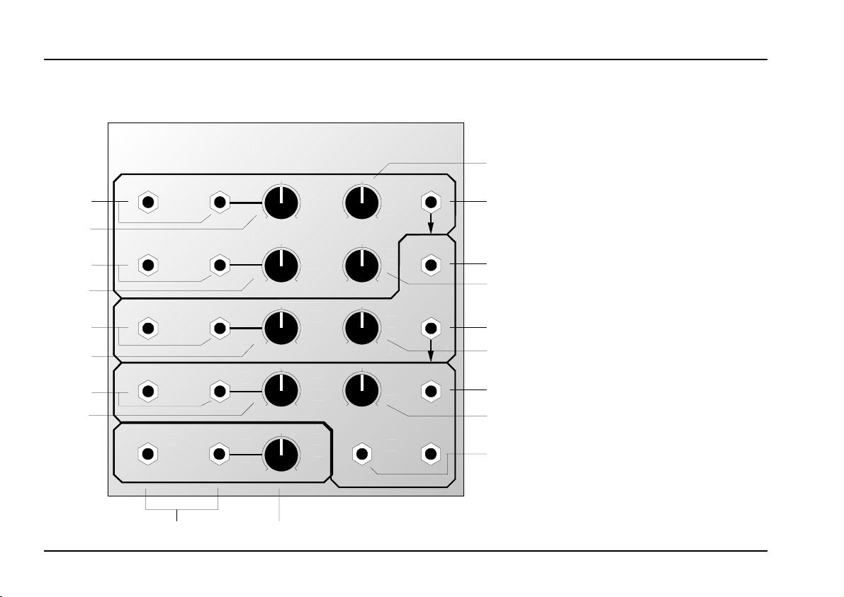
2. Overview
System A - 100
doepfer
➋
➂
➌
➄
➏
➆
➒
➈
A-109
VC Signal Processor
24 dB Low Pass / VCA / Panning
CV F2
CV F1
CVF1
VCF
10
0
CVQ2 CVQ1
CVA 2 CVA 1
CVQ1
10
0
CVA 1
VCA
10
0
CVP2 CVP1
CV P1
PA N
10
0
Audio In 2 Audio In 1
(to VC F A udio Input )
➊
Level
10
0
➀
Frq.
VCF Out
10
0
VCA In
Res .
10
0
Amp.
VCA Out
10
0
Pan In
Pan.
10
0
Pan Out L Pan Out R
➁
➍
➎
➃
➐
➅
➑
➇
➓
2
Page 3

doepfer
System A - 100
VC Signal Processor
A-109
Controls:
1 Level : Attenuator for input signal at socket !
(Audio In 1)
2 Frq. : Manual control of filter frequency
3 CVF1 : Attenuator for input signal at socket "
(CVF1)
4 Res. : Manual control of filter resonance
5 CVQ1 : Attenuator for input signal at socket §
(CVQ1)
6 Amp. : Manual control of VCA amplitude
7 CVA1 : Attenuator for input signal at socket &
(CVA1)
8 Pan : Manual panning control
9 CVP1 : Attenuator for input signal at socket )
(CVP1)
In- / Outputs:
! Audio In 1 •
Audio In 2 : VCF audio inputs
" CVF1 • CVF2 : CV inputs for filter frequency (CVF1
with attenuator)
§ CVQ1 • CVQ2 : CV inputs for filter resonance
(CVQ1 with attenuator)
$ VCF Out : Filter output
% VCA In : VCA audio input
& CVA1 • CVA2 : CV inputs for VCA amplitude (CVA1
with attenuator)
/ VCA Out : VCA output
( Pan In : Panning audio input
) CVP1 • CVP2 : CV inputs for panning (CVP1 with
attenuator)
= Pan Out L •
Pan Out R : Audio outputs of the panning unit
3
Page 4
A-109
VC Signal Processor
System A - 100
doepfer
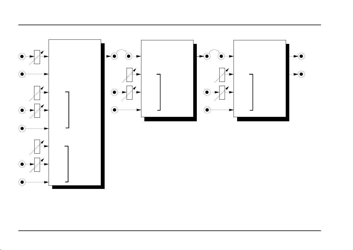
VCF
Audio In 1
Audio In 2
man.
CV 1
CV 2
man.
CV 1
CV 2
Fig. 1: A-109 structure
Res onanc e
Audio
Out
Frequency
ab
Audio In
man.
CV 1
CV 2
VCA
Amplitude
PAN
Audio
Out
The internal connections “a” and “b” are inter-
H
Audio In
man.
CV 1
CV 2
Audio
Out L
Audio
Out R
Panning
rupted as soon as a plug is inserted into the
corresponding audio input socket (normalized
switching sockets).
4
Page 5
doepfer
Q
System A - 100
VC Signal Processor
A-109
3. Controls
1 Level
Use this attenuator to control the amount of signal
entering the filter input "Audio In 1".
If the filter distorts, turn this control down, unless
H
you deliberately want the distorted sound as a
special effect. The audio input is very sensitive
so that distortion is possible even with normal
A-100 levels. Distortion appears about from position 5 with normal A-100 audio levels.
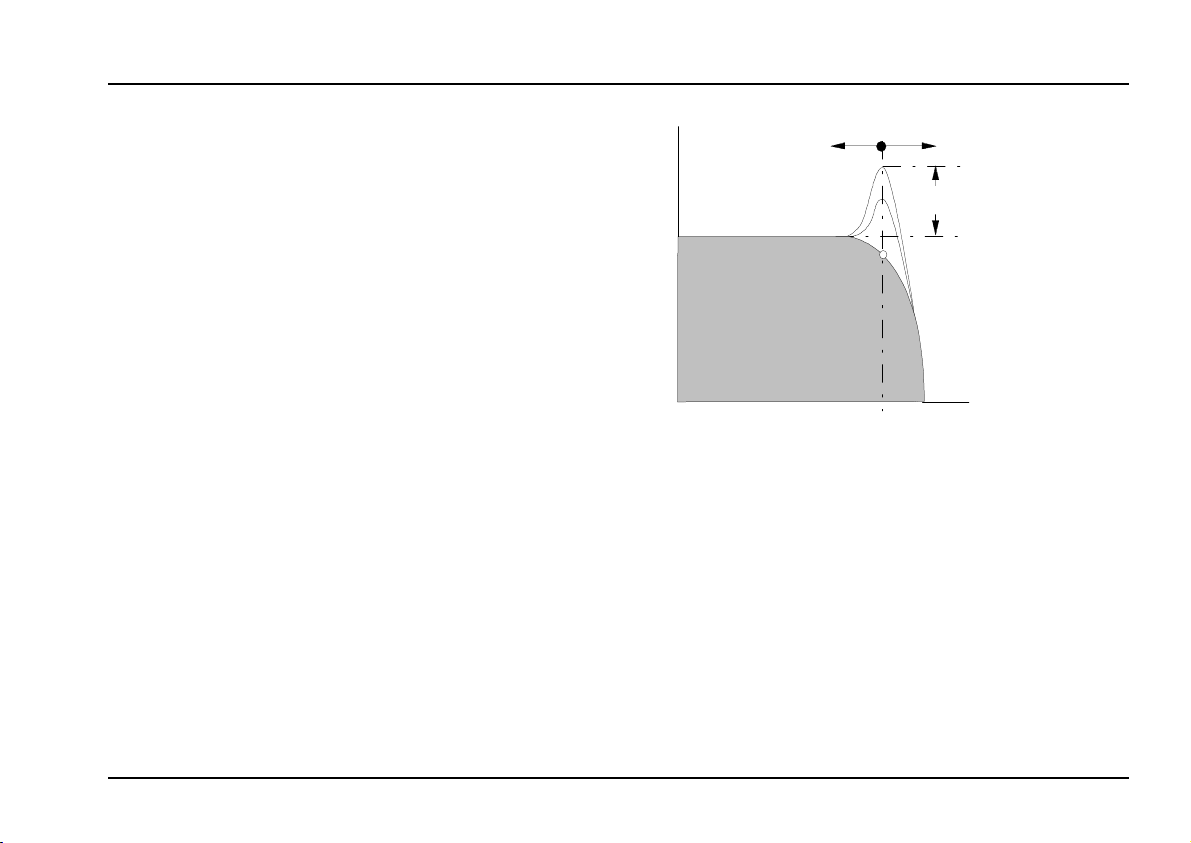
2 Frq.
Control 2 is used to adjust the filter frequency manually, i.e. the cut-off frequency f
In the maximum position of this control the low pass
filter is open. The more you turn down this control, the
more the high frequencies are filtered. The sound
becomes mellower and less bright (see Fig. 2) until at
0 the filter is completely shut, and there will be no
output signal at all.
The actual filter frequency results from the sum of the
manual control 2 and the external control inputs CVF1
and CVF2.
of the filter.
C
Out
Fig. 2: Frequency response of the filter
Frq. / CV F
f
C
Res . / CV
Freq.
3 CVF1
For voltage control or modulation of the cut-off frequency, use the frequency CV inputs ". Use attenua-
tor 3 to adjust the control voltage level of the frequency CV input CVF1.
5
Page 6

A-109
VC Signal Processor
System A - 100
doepfer
4 Res.
With this control you adjust the filter’s resonance (or
emphasis or Q factor) - the parameter which emphasises the frequencies around the cut-off point f
2). Close to its maximum setting, the filter becomes so
resonant that it goes into self-oscillation, and starts
behaving like a sine wave oscillator. You can take
advantage of this effect, and use the VCF as an
additional oscillator.
The actual resonance results from the sum of the
manual control 4 and the external control inputs
CVQ1 and CVQ2.
(see Fig.
C
5 CVQ1
For voltage control or modulation of the resonance,
use the resonance CV inputs §. Use attenuator 5 to
adjust the control voltage level of the resonance CV
input CVQ1.
6 Amp.
With this control you adjust the VCA’s amplitude (or
audio level). The main VCA has a combined expo-
nential/linear control scale:
• exponential from about 0...+200mV
(corresponding to about -100dB ... -20dB attenuation)
• linear from about 200mV...+5V (corresponding to
-20dB...0dB attenuation)
The "rounded" knee at the scale bottom allows an
envelope to decay to zero with a natural exponential
sound.
7 CVA1
For voltage control or modulation of the VCA amplitude, use the amplitude CV inputs &. Use attenuator 7
to adjust the control voltage level of the amplitude
CV input CVA1.
8 Pan
With this control you adjust the modules panning
setting - the parameter that defines the amplitude
relation between the audio outputs Pan Out L and Pan
Out R (=), resp. the position of the audio signal in a
stereophonic environment.
The middle position of this control corresponds to
equal amplitude for both outputs, resp. middle stereo
position.
6
Page 7

doepfer
System A - 100
VC Signal Processor
A-109
The actual panning setting results from the sum of the
manual control 8 and the external control inputs CVP1
and CVP2.
The gains of the panning VCAs are complementary,
beeing equal and half of maximum at about +2.5V CV.
The control scales are linear between about +1 and
+3.5V CV, becoming logarithmic beyond these extremes.
9 CVP1
For voltage control or modulation of the panning, use
the panning CV inputs ). Use attenuator 9 to adjust
the control voltage level of the panning CV input
CVP1.
4. In- / Outputs
! Audio In 1 • Audio In 2
These are the filter’s audio input sockets. Both inputs
form a miniature audio mixer. The signal at the "Audio
In 1" socket is equipped with an attenuator to adjust
the audio level of this input.
As the input "Audio In 2" does not have available
H
an attenuator high input levels may cause distortion at this audio input. To avoid this use "Audio
In 1" that is equipped with an attenuator.
" CVF1 • CVF2
These are the control voltage inputs for the filter
frequency. The control voltages of both sockets are
added to manual control 2.
CVF1 is equipped with an attenuator that allows control the level of voltage - the intensity of modulation
effect on the filter frequency - with the attenuator 3.
Socket CVF2 does not have an attenuator and works
approximately on the 1V / octave rule, like the VCOs.
7
Page 8

A-109
VC Signal Processor
System A - 100
doepfer
If you patch a modulation source (eg LFO, ADSR) to
these inputs, the cut-off frequency of the filter will be
modulated by the voltages, i.e. the sound color changes according to the voltages put out by the modulators.
If you use the VCF as a sine wave oscillator, connect
the pitch CV into the CVF2 socket. Do the same if you
want the filter’s cut-off frequency to track with the pitch
of a note.
§ CVQ1 • CVQ2
These are the control voltage inputs for the filter
resonance. The control voltages of both sockets are
added to manual control 4.
CVQ1 is equipped with an attenuator that allows
control the level of voltage - the intensity of resonace
modulation on the filter - with the attenuator 5.
Socket CVQ2 does not have an attenuator. The voltage range for this input is approximately 0...+5V (0V =
no resonance, ~ +4...5V = self oscillation).
If you patch a modulation source (eg LFO, ADSR,
sequencer, random CV) to these inputs, the resonance of the filter will be modulated by the voltages.
$ VCF Out
Socket % is the audio output of the filter. The socket
is connected to the audio input of the VCA (see fig. 1).
% VCA In
This socket is the audio input of the VCA. It is
internally connected to the VCF output $ (normalized
socket) provided that no plug is inserted into the
socket %.
& CVA1 • CVA2
These are the control voltage inputs for the VCA
amplitude. The control voltages of both sockets are
added to manual control 6.
CVA1 is equipped with an attenuator that allows control the level of voltage - the intensity of amplitude
modulation on the VCA - with the attenuator 5.
Socket CVA2 does not have an attenuator. The voltage range for this input is approximately 0...+5V.
/ VCA Out
Socket / is the audio output of the VCA. The socket
is connected to the audio input of the panning section.
8
Page 9

doepfer
System A - 100
VC Signal Processor
A-109
( Pan In
This socket is the audio input of the Panning section. It is internally connected to the VCA output /
(normalized socket) provided that no plug is inserted
into the socket (.
) CVP1 • CVP2
These are the control voltage inputs for the Panning
section. The control voltages of both sockets are
added to manual control 8.
CVP1 is equipped with an attenuator that allows control the level of voltage - the intensity of panning
modulation - with the attenuator 9.
Socket CVP2 does not have an attenuator. The voltage range for this input is approximately 0...+5V.
A typical application is the periodical "walking" of a
signal in the stereo panorama. For this the triangle or
sine output of a LFO is connected to one of the sockets
) to control the panning.
= Pan Out L • Pan Out R
5. User Examples
Module A-109 makes available three important basic
modules: 24dB low pass (VCF), VCA and PAN. At
least VCF and VCA are required for most of the
standard synthesizer patches. The sub-modules are
usefully pre-patched to minimize the required external
patches.
Because of the normalized audio input sockets the
sub-modules of the A-109 can be used even separately from each other.
As the A-109 is nothing but a collection of modules that
are still available in the A-100 please look at the
examples in the manuals for the A-100 filters (e.g.
A-102, A-103, A-105, A-108, A-120, A-122), VCAs
(e.g. A-130, A-131, A-132) and the separate panning
module (A-134) to find some typical applications.
These sockets are the left resp. right audio output of
the panning section.
9
Page 10

A-109
VC Signal Processor
6. Patch-Sheet
System A - 100
doepfer
The following diagram of the modules can help you
recall your own Patches. They’re designed so that a
complete 19” rack of modules will fit onto an A4 sheet
of paper.
Photocopy this page, and cut out the pictures of this
and your other modules. You can then stick them
onto another piece of paper, and create a diagram of
your own system.
Make multiple copies of your composite diagram, and
use them for remembering good patches and set-ups.
P
• Draw in patchleads with colored pens.
• Draw or write control settings in the little
white circles.
A-109
VC Signal Processor
24 dB Low Pass / VCA / Panning
CV F2
CV F1
CV F1
VCF
10
0
CVQ2 CVQ 1
CVA 2 CVA 1
CVQ1
10
0
CVA 1
VCA
10
0
CV P2 CVP1
CV P1
PAN
10
0
Audio In 2 Audio In 1
(to V CF A udio In put )
Leve l
10
0
Frq.
VCF Out
10
0
VCA In
Res.
10
0
Amp.
VCA Out
10
0
Pan In
Pan .
10
0
Pan Out L Pan Out R
10
 Loading...