

Page 1
doepfer
System A - 100
1. Introduction
Trautonium Formant Filter
A-104
Input
Leve l
A-104
Audio
In
Level
Frequency
VCF 1
Reso na n ce
Mode
VCF 2 VCF 4
Audio
Out
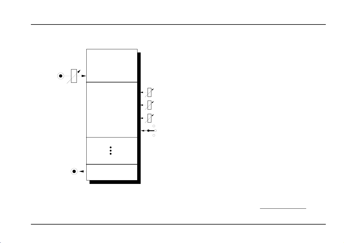
Module
“Mixtur Trautonium” by Oskar Sala. It is made of
four parallel resonance filters with common input
and output (see fig. 1 on page 3). Each filter can be
switched to low pass or band pass or off. Frequency,
resonance, mode
trolled for each filter separately by hand (no voltage
control !). The frequency range for each filter is about
50Hz...5kHz.
The input level for all filters is controlled by an attenuator. The filter audio inputs are very sensitive so
that distortion may intentionally be used to create new
sounds - if desired.
The A-104 is a versatile module for sound modifica-
tion. In the first place it is used for reproduction of
resonances (e.g. the vocal-like effects known from
the Trautonium). In combination with the
nic generator A-113 one obtains the complete replica
of the Trautonium sound generation.
More detailed information about the Trautonium can
be found on our internet site www.doepfer.com
is a replica of the
A-104
Formant Filter
(band/low/off) and
are con-
level
subharmo-
.
of the
1
Page 2
A-104
Trautonium Formant Filter
System A - 100
doepfer
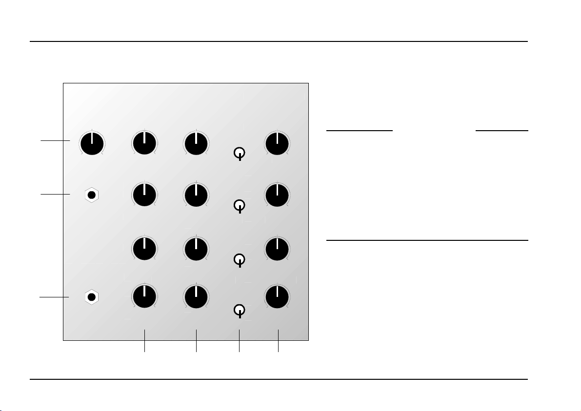
2. TFF - Overview
➀
➊
➋
A-104
Input Level Frequency Resonance Mode Level
10
0
Audio In
Audio Out
Trautonium Formant Filter
0
0
0
0
Controls:
1 Input Level : Attenuator for audio input
signal (effective for all filters)
Band
10
10
10
10
10
0
Band
0
10
Band
0
10
Band
0
10
Low
Low
Low
Low
0
0
0
0
1
: Frequency control
Frq.
10
10
2
Resonance : Resonance control (Q, em-
3
2
Mode : Mode switch (band/off/low)
4
5 Level : Level control (share of the
3
10
10
In- / Outputs:
Audio In : Common filter audio input
!
4
" Audio Out
For each VCF:
phasis)
filter signal in the mix output)
: Common filter audio output
➁
➂
➃
➄
2
Page 3

doepfer
Fig. 1: Sketch of the A-104
3. Controls
System A - 100
Trautonium Formant Filter
A-104
1 Input Level
Attenuator 1 adjusts the level of the audio input signal
applied to the audio input socket !. The attenuated
signal is fed to each of the four resonance filters.
H The audio inputs of the filters are very sensitive
so that distortion - even with normal A-100
audio levels (e.g. VCO A-110) - may intentionally be used to create new sounds. Distortion
appears about from the middle position of the
input level control 1.
3
Page 4

A-104
Trautonium Formant Filter
System A - 100
doepfer
Out
Frq.
f
Out
Res.
M
Freq.
Frq.
f
C
Res.
Freq.
Fig. 2: Frequency response of band pass and low
pass
2 Freq.
Control 2 is used to adjust the
filter frequency
fig. 2):
• In band pass mode i.e. the middle frequency f
• In low pass mode i.e. the cutoff frequency f
The frequency range for each filter is about 50Hz ...
5kHz (same as for the Trautonium filter).
(see
M
C
3 Resonance
Control 3 is used to adjust the filter resonance (or
emphasis or Q, see fig. 2):
In band pass mode i.e. the band width
•
•
In
low pass
mode i.e.
frequency emphasis
around the cutoff frequency
Self-oscillation - as for some other filters of the A-100
(e.g. A-120, A-121, A-122, A-123 and so on) - is not
available.
4 Mode
The three-position switch 4 is used to select the
of the corresponding filter:
• band pass (upper position)
• off (middle position)
• low pass
(lower position).
mode
5 Level
Attenuator 5 is used to adjust the signal level of the
corresponding filter (share in the mix output socket ").
4
Page 5

doepfer
System A - 100
Trautonium Formant Filter
A-104
4. In- / Outputs
! Audio In
This is the filter’s
output from the sound source (e.g. Subharmonic Generator A-113, VCO A-110/A-111, Noise Generator
A-117/A-118, Mixer A-138).
audio input
" Audio Out
Filter output
i.e. the sum signal of the four resonance filters.
socket " sends out the filtered signal,
socket. Patch in the
5. User Examples
Module A-104 is used in the first place for the simula-
of
tion
Even vowel-like effects may be generated with this
module (refer to the user’s manuals of A-127 and
A-128).
In combination with the Subharmonic Generator A-
113
Trautonium sound generation (refer to the user’s
manual of A-113 on page 11 for the complete sketch).
More detailed information about the Trautonium and
the realization with A-100 modules can be found on
our internet site www.doepfer.com
A module that’s related very close to the A-104 is the
A-127 Voltage Controlled Resonance Filter
contrast to the A-104 the filter frequencies are voltage
controlled and each filter has an own LFO for frequency modulation. This enables automatic filter
sweeps or multiple voltage controlled filtering (e.g. with
sequencer or MIDI-to-CV interface).
For filter applications with fixed frequencies the
Filter Bank A-128 may be used.
resonances
one obtains a nearly complete replica of the
.
.
. In
Fixed
5
Page 6

A-104
Trautonium Formant Filter
6. Patch-Sheet
System A - 100
doepfer
The following diagrams of the module can help you
recall your own Patches. They’re designed so that a
complete 19” rack of modules will fit onto an A4 sheet
of paper.
Photocopy this page, and cut out the pictures of this
and your other modules. You can then stick them
onto another piece of paper, and create a diagram of
your own system.
Make multiple copies of your composite diagram, and
use them for remembering good patches and set-ups.
P
• Draw in patchleads with colored pens.
• Draw or write control settings in the little
white circles.
A-104
Input Lev el Freq uen cy Reso nanc e Mo de Leve l
0
Audio In
Audio Out
Trautonium Formant Filter
10
0
10
10
0
0
10
10
0
10
0
0
10
0
10
0
10
Band
Low
Band
Band
Band
0
0
Low
0
Low
0
Low
1
10
2
10
3
10
4
10
6
 Loading...