

Page 1

doepfer
System A - 100
Modular Vactrol Phaser
A-101-3
1. Introduction
Module A-101-3 is a 12 stage phase shifter with vactrols as phase shifting elements. A vactrol is a combina-
tion of a light depending resistor (LDR) and LED both
put into a light-proof case. They are known for their
smooth sound behaviour as vactrols are distortion-free
linear elements in contrast to any semiconductor (like
transistors or OTA in other designs). For more general
details about vactrols please look at the vactrol basics
page on our web site www.doepfer.com.
In contrast to other phaser designs the A-101-3 is much
more flexible and offering a lot of new features not
available from other phasers on the market. The A-1013 offers access to each of the 12 input and output
stages leading to a lot of new filters that cannot be
obtained in other ways. Especially the free patchable
(yes, not only one feedback loop is
feedback loops
possible) between each of the 12 stages, the separate
phase shift control for the stages 1-6 and 7-12, and
the 2 polarizers intended to control the feedback loops
lead to completely new filter types (a polarizer is a
circuit that is able to generate positive and negative
amplifications in the range -1...0...+1 with -1 = inversion,
0 = full attenuation, +1 = unchanged signal, for details
concerning the polarizer function please look at the
A-133 VC Polarizer or A-138c Polarizing Mixer module).
On our web site are lot of frequency response curves
availabe that show which filter types can be realized.
Internally the module is made of 2 independent 6 stage
phase shifters (1-6 reps. 7-12) with separate audio
inputs (with attenuators), audio outputs (with mix con-
trol), and phase shift control units. The phase shift
control units feature both manual and voltage controlled
phase shifting (e.g. from a LFO, ADSR, Random Voltage, Theremin CV, Foot Controller CV ...). For each
sub-module a phase shift display (LED) is available.
The LED shows the illumination state of the 6 vactrols of
the sub-module in question as it is connected in series
with the internal vactrol LEDs.
Each of the 12 phase shift stages is equipped with an
audio output socket and feedback input socket to
obtain full flexibility to create a multitude of different
filters. The audio input signal and the output signals of
stage 6 resp. stage 12 are mixed with 2 manual controls
to obtain effects at two audio outputs (for normal
phase shifting effect this is 50% input signal and 50%
phase shifted signal).
The two submodules are internally connected via nor-
malled sockets so that two 6 stage phase shifters can
be obtained without external patches.
1
Page 2
A-101-3
Modular Vactrol Phaser
System A - 100
doepfer
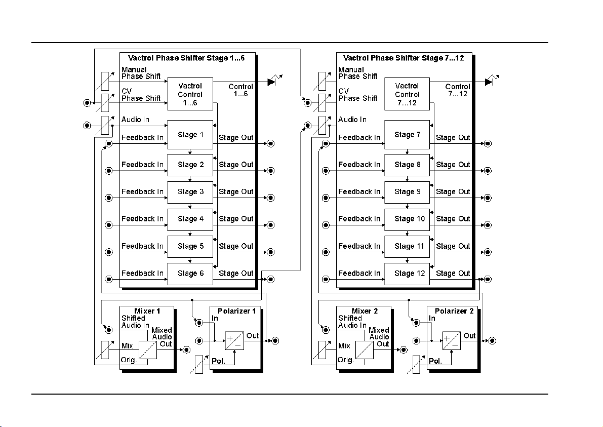
Fig.1: A-101-3 Overall view
2
Page 3

doepfer
System A - 100
Modular Vactrol Phaser
A-101-3
2. Basic principles
The module is made of two identical units that differ
only in the normalling of the sockets (i.e. how the
switching contacts of some sockets are internally
pre-wired). Therefore only one of the two units is
described with reference to fig. 1 on the preceding
page. The stages 1-6 belong to the first unit, 7-12 to
the second one. Some basics concerning the function
of a phaser (frequency response, comb filter) can be
found in the manual of the VC phaser A-125 too.
The vactrol control unit is made of a logarithmic
voltage-to-current converter that converts the sum
of the manual phase shift setting and the external
control voltage into a current. This current is used to
drive the 6 LEDs inside the vactrols of the phase
shift stages and the display LED. The 6 photo resi-
stors inside the vactrols that work as phase shift
controlling elements respond to the illumination intensity and create different phase shifts for different
illuminations.
The (attenuated) audio input signal is fed into the first
phase shift stage (stage 1). The 6 phase shift stages
are daisy-chained. Each stage is equipped with it's
own audio output (stage out) and feedback input.
The sum of the feedback input and the output of the
preceding stage are mixed and fed into the corresponding phase shift stage.
This modular concept allows the realization of dif-
ferent phasers as well as a lot of other filters too as
all inputs and outputs are free patchable. For example
phasers with 2 up to 12 stages, phasers with free
eligible simple or multiple feedback loops or parallel
working phasers are possible. On our web site a lot of
frequency response curves are available that show
which types of phasers and filters are possible with
this modular concept.
The module contains two additional circuits: a mixer
and a polarizer (one for each unit).
The mixer is used to combine the incoming original
audio signal (audio In) with the phase shifted signal
(shifted audio In) with adjustable ratio. The typical
setting for a phaser is 50:50, i.e. both the original and
the shifted signal have the same level. This creates
the typical phaser jet sound that is based on the
comb-like frequency response curve. But even different ratios make sense. If only the phase shifted
signal is used one obtains the so-called phase vi-
brato effect. The socket "Shifted Audio In" is normalled to stage output 6. Consequently a 6-stage phaser
is obtained at the socket "Mixed Audio Out" provided
3
Page 4

A-101-3
Modular Vactrol Phaser
System A - 100
doepfer
that no plug is inserted into this socket. To obtain a
phaser with more or less stages the output of the corresponding stage has to be connected to the socket
"Shifted Audio In". To obtain e.g. a 12-stage phaser the
output of stage 12 has to be connected to "Shifted Audio
In" of mixer 1.
The polarizer is intended to control the feedback
loops. In principle a polarizer is an attenuator. But in
contrast to a normal attenuator it enables both positive
and negative attenuations (i.e. amplifications in the
range -1...0...1). Negative attenuation resp. amplifications means that the signal is inverted (look at the manuals of A-133 CV Polarizer or A-138c Polarizing Mixer for
details). The middle position of the polarizer control
corresponds to full attenuation (or amplification = 0).
This corresponds to the fully counterclockwise position
of a "normal" attenuator. The fully clockwise position
corresponds to amplification +1 (i.e. the signal passes
unchanged), the fully counterclockwise position corresponds to amplification -1 (i.e. the signal is inverted).
The "Polarizer In" socket is normalled to stage output 6.
Consequently the output of stage 6 is used as polarizer
input provided that no plug is inserted into this socket.
The polarizer output is normalled to "Feedback In Stage
stage 1"
1". Consequently the feedback loop "stage 6
is active without external patches and the polarizer
control is used to adjust the feedback intensitiy and
polarity (remember: zero feedback corresponds to
→→→→
middle position). On our web site a lot of examples of
single and multipe feedback loops are published
(available via A-101-3 information page).
And this is the result from all these response curves:
The number of notches is defined by the num-
•
ber of stages used as output (number of notches = integer of the stage number/2)
The number of resonance peaks is defined by
•
the number of stages used for feedback
(number of peaks = integer of number of feedback stages used/2)
The height of the resonance peaks is deter-
•
mined by the amount of resonance (adjusted
with the polarizer)
By means of the open modular concept of the module
A-101-3 different numbers of notches and peaks are
possible by using the corresponding patch for output in
use and feedback loop(s) !
4
Page 5

doepfer
System A - 100
Modular Vactrol Phaser
A-101-3
3. Overview
3
&
"
2
§
$
4
! 1(/
6
%
5
5
Page 6

A-101-3
Modular Vactrol Phaser
System A - 100
doepfer
Controls:
1 Level: attenuator for audio input !
2 CV: attenuator for CV input "
3 Shift: manual phase shift
4 Mix: mixing ratio between original and phase
shifted signal
5 Pol.: polarizer control
6 Shift: LED display for pase shift
(= brightness of the LEDs inside the
vactrols)
Only the elements of one of the two identical phase shift units is specified. The second unit is identical with these
exceptions:
• "Audio In 7-12" is normalled to output stage 6 (i.e. all 12 stages are daisy-chained - even between stage 6 and
stage 7 - provided that no plug is inserted into socket "Audio In In 7-12")
• "CV In 7-12" is normalled to socket "CV In 1-6" (i.e. same CV for both units provided that no plug is inserted
into socket "CV In 7-12")
Inputs / Outputs:
! Audio In: Audio input
" CV In: Control voltage input
§ Shifted Audio In: Mixer input for phase shifted si-
gnal (normalled to output stage
6)
$ Mixed Audio Out: Mixer output (= phase shifter
audio output)
% Polarizer In: Polarizer input (two sockets,
one is normalled to output stage
6)
& Polarizer Out: Polarizer output
/ Feedback In: Feedback inputs (6x, feedback
In 1 is normalled to polarizer
output)
( Stage Out: Phase shifter outputs (6x)
6
Page 7

doepfer
System A - 100
Modular Vactrol Phaser
A-101-3
4. Controls
! Audio In / 1 Level
Socket ! is the audio input with the assigned attenuator
1. Feed the audio signal that has to be provided with the
phaser/filter effect into socket !. Adjust the
1 so that the output signal does not distort - unless you
want to obtain distortion. For normal A-100 levels (e.g.
VCO A-110) distortion appears at about middle position
of control 1. The input was made a bit more sensible
than for other modules to be able to obtain distortion
without an additional module. Distortion might be interesting with certain feedback settings.
Attention:
7-12 is normalled to stage output 6 of the left unit ! This
simplifies the patching of phasers with more than 6
stages as the output of stage 6 is connected to the audio
input of stage 7 provided that no plug is inserted into
socket
separate phasers/filters each unit is supplied with it's
own audio signal that is connected to socket ! (Audio In
In 1-6 resp. Audio In In 7-12).
" CV In / 2 CV / 3 Shift
This group of elements is responsible for the phase shift
control. Knob 3 Shift
manually. With an external control voltage (e.g. LFO,
For the right unit the audio input ! Audio In In
Audio In In 7-12
. If both units are used as
is used to adjust the phase shift
Level
control
Random, ADSR, Theremin, Ribbon controller, foot controller, MIDI-to-CV) applied to socket " CV In
shift can be modulated. Knob 2 CV is used to adjust the
depth of the CV modulation.
Attention: For the right unit the socket " CV In 7-12 is
normalled to socket " CV In 1-6. This simplifies patches
with identical CVs for both units (e.g. phasers with more
than 6 stages) as the phase shift controls of both units
are supplied with the same control voltage (applied to
socket " CV In 1-6
into socket socket " CV In 7-12
operated separately even separate CVs are applied to
the CV input sockets.
The voltage difference required at socket " to take
advantage of the full phase shift range is about 5V (with
attenuator 2 fully clockwise).
4 Mix / § Shifted Audio In / $ Mixed Audio Out
Knob 4 Mix is used to adjust the ratio between the
original audio signal (i.e. the signal applied to socket !)
and the signal at socket § Shifted Audio In. Socket $
Mixed Audio Out
audio output of the phaser.
Socket § is normalled to stage output 6. Provided that
no plug is inserted into socket § one obtains a 6 stage
phaser at output $ Mixed Audio Out. If another stage
output is connected to socket § phasers with 2 - 12
) provided that no plug is inserted
. If both units are
is the mixer output and normally the
the phase
7
Page 8

A-101-3
Modular Vactrol Phaser
System A - 100
doepfer
stages can be obtained. The output of stage 1 does not
lead to a phaser but a high pass or low pass according
to the polarity of the signal fed into socket §. E.g. one of
the polarizers can be used to define the polarity and to
fade from highpass to lowpass and vice versa. To obtain
a phaser with 7-12 stages the output of stage 7-12 has
to be connected to socket §
(!) unit as only here the original signal is available as the
second input of the mixer (the mixer of the right unit
does not have available the original that is connected to
audio input ! of the left unit).
% Polarizer In / & Polarizer Out / 5 Pol.
These elements correspond to the polarizer. The working principle of the polarizer is described in chapter 2.
The two sockets % Polarizer In
multiple" and are the input of the polarizer. Socket &
Polarizer Out is the output of the polarizer.
The function of the polarizer (i.e. the amplification in the
range -1...0...+1) is determined by the position of control
5 Pol.
The left one of the sockets % Polarizer In
stage output 6. The output of the polarizer is normalled
to the feedback input of stage 1 (/ Feedback In 1).
Provided that no plugs are inserted a feedback loop from
stage 6 to stage 1 is established. In the middle position
of control 5
clockwise position maximum negative, at fully clockwise
position maximum positive feedback occurs.
no feedback occurs. At fully counter-
Pol
Shifted Audio In
form a "miniature
of the left
is normalled to
To obtain different feedback loops the sockets % Polari-
zer In and & Polarizer Out have to be connected with
the desired output stages resp. feedback inputs.
By using the second polarizer or external modules (e.g.
VCA, VC polarizer A-133, filter, distortion, waveshaper)
even multiple feedback loops are possible - leading to
very interesting frequency responses with multiple resonance peaks.
Another special feature of the A-101-3 are "forward
loops", i.e. it is possible to feed a stage output to a
feedback input of a higher stage (via polarizer).
By means of multiple feedbacks and/or forward loops in
combination with the positive/negative amplifications of
the polarizers and different controls and patches of the
stages 1-6 resp. 7-12 very complex frequency response
curves can be realized that cannot be obtained in any
other way.
/ Feedback In (6x)
These are the feedback inputs of the phase shifting
stages. Applications of these inputs have been described on the preceding pages. The feedback input of
stage 1 is normalled to the polarizer output, i.e. Feed-
back In 1 is connected to the polarizer output - provided
that no plug is inserted into socket / Feedback In 1
.
8
Page 9

doepfer
System A - 100
Modular Vactrol Phaser
A-101-3
( Stage Out (6x)
These are the outputs of the phase shifting stages.
Applications of these outputs have been described on
the preceding pages. The output of stage 6 is normalled
to socket §
sockets % Polarizer In
Shifted Audio In
and to the left one of the two
.
5. User Examples
not yet ready
9
Page 10

A-101-3
Modular Vactrol Phaser
System A - 100
doepfer
10
 Loading...