

Page 1
doepfer
System A - 100
Vactrol Lowpass Gate
A-101-2
1. Introduction
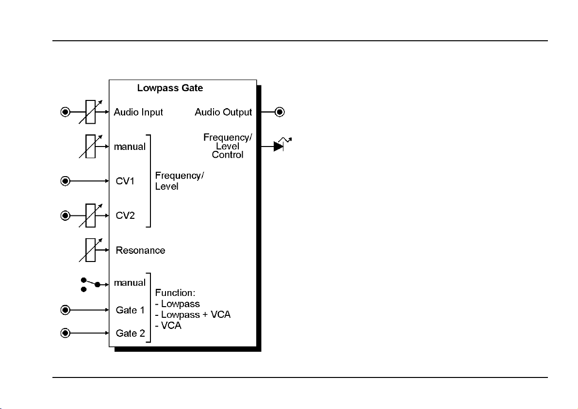
Module A-101-2 is a vactrol based combination of
Low Pass filter (LP) and VCA. Additionally a combined
mode LP+VCA is available. In this mode the sound
becomes more dull as the loudness decreases.
The A-101-2 was inspired by module 292 of Don Buchla.
He also intruduced the term "Low Pass Gate" for this
combination of functions.
The function of the module is controlled by a manual
switch or by two gate inputs.
In principle the A-101-2 is a 12 dB low pass that can be
switched to VCA or a combination of Low Pass and
VCA. The controlling elements for frequency resp. loudness are so-called vactrols. A vactrol is a combination
of a light depending resistor (LDR) and a light emit-
ting diode (LED) both put into a small light-proof case.
Vactrol based circuits are known for their soft low-
distortion sound. For details about vactrols please use
the corresponding link in the A-101-2 info page on our
web site www.doepfer.com.
Frequency resp. loudness is controlled manually and
by two control inputs.
The audio input is very sensitive in filter mode to obtain
distortion effects if desired.
The resonance function "colors" to the sound and is
adjustable all the way up to self-oscillation.
In contrast to the Buchla design the A-101-2 offers the
resonance feature, attenuators for both CV and audio
input, and two gate inputs to control the function of the
module in addition to the manual toggle switch.
1
Page 2
A-101-2
Vactrol Lowpass Gate
2. Overview
"
System A - 100
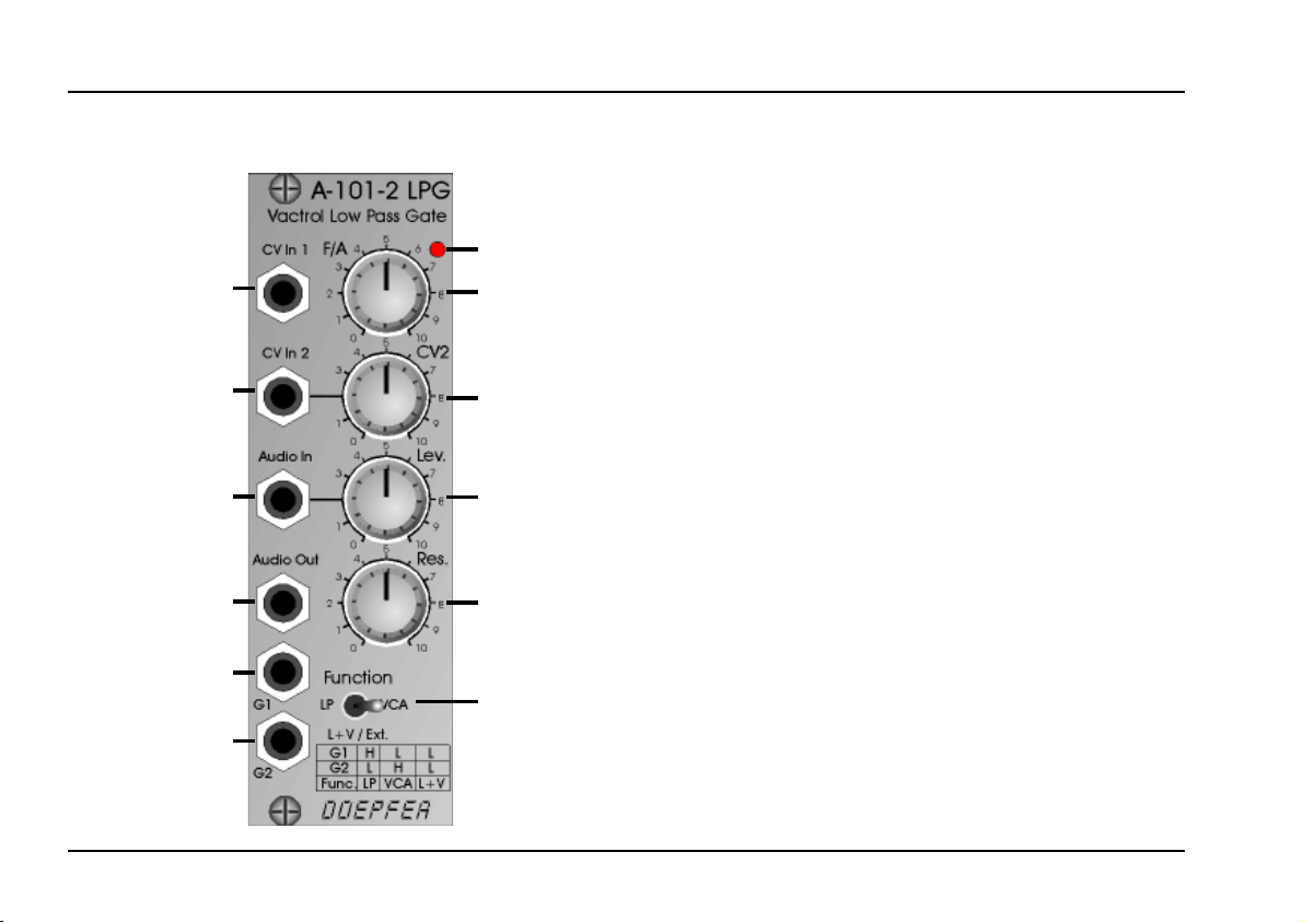
Controls:
1 F/A manual frequency/loudness control
6
1!
2
2 CV2 attenuator for CV input "
3 Level attenuator for audio input §
4 Resonance resonance control
5 Function function toggel LP / LP+VCA / VCA
6 LED control for frequency/loudness
Inputs / Outputs:
doepfer
§
$
%a
3
4
! CV In 1 frequency/loudness CV input 1
" CV In 2 frequency/loudness CV input 2
§ Audio In audio input
$ Audio Out audio output
%a G1 function control input 1 (gate 1)
%b G2 function control input 2 (gate 2)
5
%b
2
Page 3

doepfer
System A - 100
Vactrol Lowpass Gate
A-101-2
3. Controls / Inputs / Outputs
1 F/A (control) / ! CV In 1 (socket)
2 CV2 (control) / " CV In 2 (socket)
This group of elements is responsible for the filter frequency resp. loudness (audio level / amplitude) according to the selected function. Control 1 F/A is used to
adjust the frequency resp. loudness manually. The control voltage inputs ! CV In 1 and " CV In 2 enable
voltage control of the frequency resp. loudness by
means of external voltages (e.g. ADSR, LFO, random
voltage, S&H). The input " CV In 2 is equipped with the
attenuator 2 CV2. Input ! CV In 1 has no attenuator
available.
Remark:
control frequency and resp. loudness. The light depending resistors inside the vactrols show a considerable
slowness of the resistance variation. Consequently frequency resp. loudness changes are not as fast as for
other A-100 filters or VCAs that do not use vactrols. Fast
attacks or decays (CV = ADSR) or FM effects in audio
range (CV = LFO or VCO) are not possible with vactrol
based circuits. Please use one of the other A-100 filters
or VCAs for these purposes. By means of a LFO with
gradually increasing frequency one can discover the
maximum modulation frequency that the vactrols are
able to follow.
Module A-101-2 uses so-called vactrols to
The LED near the frequency control 1 is a rough
measure of the current frequency resp. loudness. This
LED is connected in series with the LEDs inside the
vactrols and consequently shows the current illumination
inside the vactrols.
Due to the"crooked" response of
not an exact control standard (like V/Oct or dB/V). The
inevitable tolerances and tracking errors between different vactrols will also lead to an individual sound of each
module and individual frequency and resonance behaviour.
3 Level (control) / § Audio In (socket)
This is the audio input of the module with the corresponding level control (attenuator). At socket § the audio
signal to be processed by the module is fed in (e.g. VCO
output).
The audio input is very sensitive in the low pass mode so
that even distorted sounds can be obtained - especially
for higher resonance settings. From about middle position ( ~ 5) distortion appears with A-100 standard audio
signals (e.g. VCO output). Even in the VCA and combined LP+VCA mode distortions are possible. But they are
distinctly smaller than in low pass mode.
vactrol
s the filter has
3
Page 4

A-101-2
Vactrol Lowpass Gate
System A - 100
doepfer
4 Resonance (control)
In low pass mode this is the resonance control. The
resonance function "colors" to the sound and is adjustable all the way up to self-oscillation. Due to the
vactrol tolerances and tracking errors mentioned above
resonance resp. self-oscillation deviations over the frequency range may occur.
In the VCA mode control 4 only changes the overall
loudness.
In the combined LP+VCA mode control 4 affects both
loudness and resonance.
The resonance function was not available for Buchla's
low pass gate. To reproduce the original Buchla sound
the resonance control simply has to be set fully counterclockwise.
$ Audio Out (socket)
This socket is the audio output of the module. According
to the selected mode the low pass filtered resp. amplitude modulated input signal appears.
5 Function (toggle switch)
%a G1 (socket) / %b G2 (socket)
This group of elements serves to select the desired
function resp. mode. These three functions are available:
Function Switch
position
low pass LP high low
low pass + VCA L+V/Ext. low low
VCA VCA low high
The function can be selected with the toggle switch 5 or
the two gate inputs %a G1 and %b G2. If the gate inputs
are used to selected the function the toggle switch has to
be in middle position L+V/Ext. (i.e. the grey shaded area
in the above table).
For the gate inputs "low" corresponds to a control voltage range of about 0...+2V, "high" corresponds to about
+3...+12V.
G1 G2
4
Page 5

doepfer
4. User Examples
not yet ready
System A - 100
Vactrol Lowpass Gate
A-101-2
5
Page 6

A-101-2
Vactrol Lowpass Gate
System A - 100
doepfer
6
 Loading...