

Page 1
doepfer
System A - 100
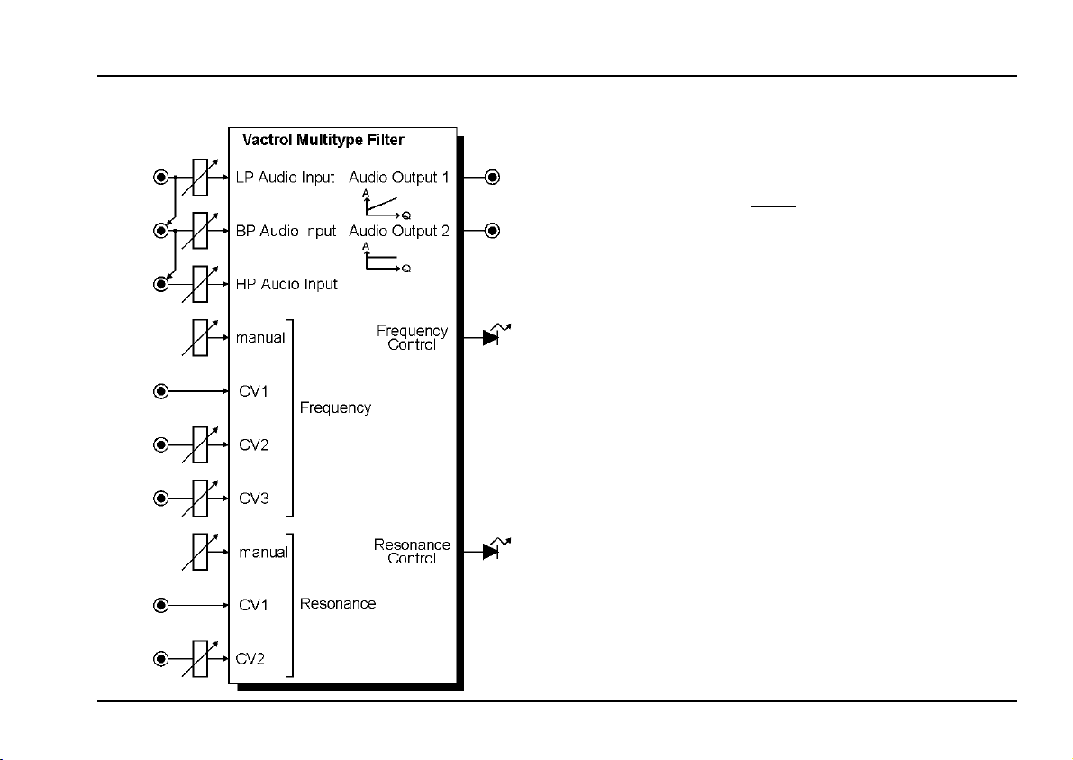
Vactrol Multitype Filter
A-101-1
1. Introduction
Module A-101-1 is a special multitype filter based on
an idea by Nyle A. Steiner from the year 1974. Injecting
an audio signal into different points of a standard low
pass filter circuit leads to the three filter types low pass
(LP), band pass (BP) amd high pass (HP). For each
filter type a separate input
the three filtered signals appears at the common out-
put. Even a notch filter can be realized.
In contrast to the original circuit so-called
used instead of diodes as variable resistors for fre-
quency and resonance control. A vactrol is a combination of a light depending resistor (LDR) and a light
emitting diode (LED) both put into a small light-proof
case. Vactrol based circuits are known for their soft
low-distortion sound. For details about vactrols and
the A-101-1 circuit principles please use the corresponding links in the A-101-1 info page on our web site
www.doepfer.com.
The three filter audio inputs are normalled via swit-
ching sockets, i.e. the BP input is connected to the LP
jack socket provided that no cable is plugged into the BP
socket (same applies for HP/BP inputs). Each audio
input is equipped with an attenuator. The audio inputs
are very sensitive and enable distorted sounds too.
For both frequency and resonance manual control and
several control voltage inputs are available.
Two LEDs display the current frequency and reso-
nance settings.
is available and the sum of
vactrols
are
1
Page 2

A-101-1
Vactrol Multitype Filter
System A - 100
doepfer
2. Overview
a
9
!
1
"
2
§
3
$
4
%
5
Controls:
1 Frequency manual frequency control
2 CVF2 attenuator for FCV input "
3 CVF3 attenuator for FCV input §
4 Emphasis manual resonance control
5 CVQ2 attenuator for QCV input %
&
6 LP attenuator for LP audio input &
6
7 BP attenuator for BP audio input /
8 HP attenuator for HP audio input (
/
9a/b LED controls for frequency and resoance
7
Inputs / Outputs:
(
! CVF In 1 frequency control voltage input 1
" CVF In 2 frequency control voltage input 2
8
§ CVF In 3 frequency control voltage input 3
$ CVQ In 1 resonance control voltage input 1
a
)
% CVQ In 2 resonance control voltage input 2
& LP In low pass audio input
b
)
/ BP In band pass audio input
( HP In high pass audio input
b
9
)a Out 1 audio output 1
)b Out 2 audio output 2
2
Page 3

doepfer
System A - 100
Vactrol Multitype Filter
A-101-1
3. Controls / Inputs / Outputs
1 Frequency (control) / ! CVF In 1 (socket)
2 CVF2 (control) / " CVF In 2 (socket)
3 CVF3 (control) / § CVF In 3 (socket)
This group of elements is responsible for the filter frequency. Control 1 Frequency is used to adjust the
frequency manually. The control voltage inputs ! CVF
In 1, " CVF In 2 and § CVF In 3 enable voltage control
of the filter frequency by means of external voltages (e.g.
ADSR, LFO, random voltage, S&H). The inputs " CVF
In 2 and § CVF In 3 are equipped with the attenuators
2 CVF2 and 3 CVF3. Input ! CVF In 1 has no attenua-
tor available.
Remark:
control frequency and resonance. The light depending
resistors inside the vactrols show a considerable slowness/inertia of the resistance variation. Consequently
frequency changes are not as fast as for other A-100
filters that do not use vactrols. Fast attacks or decays
(CV = ADSR) or FM effects in audio range (CV = LFO or
VCO) are not possible with vactrol based circuits. Please
use one of the other A-100 filters for these purposes. By
means of a LFO with gradually increasing frequency one
can discover the maximum modulation frequency that
the vactrols are able to follow.
Module A-101-1 uses so-called vactrols to
The LED right from the frequency control 1 is a rough
measure of the current filter frequency. This LED is
connected in series with the LEDs inside the vactrols
and consequently shows the current illumination inside
the vactrols.
Due to the"crooked" response of
not an exact frequency control standard (like V/Oct). The
inevitable tolerances and tracking errors between different vactrols will also lead to an individual sound of each
module and individual frequency and resonance behaviour (see below).
4 Emphasis (control) / $ CVQ In 1 (socket)
5 CVQ2 (control) / % CVQ In 2 (socket)
This group of elements is responsible for the filter resonance (emphasis, Q factor). Even the resonance control
is realized with vactrols. Consequently this parameter is
voltage controlled, too. Control 4 Emphasis is used to
adjust the resonance manually. The control voltage inputs $ CVQ In 1 and % CVQ In 2 enable voltage
control of the resonance by means of external voltages.
Input % CVQ In 2 is equipped with the attenuator 5
CVQ2. Input $ CVQ In 1 has no attenuator available.
The LED right from the resonance control 4 is a rough
measure of the current filter resonance. Same remarks
as for the frequency LED applies (see above).
vactrol
s the filter has
3
Page 4

A-101-1
Vactrol Multitype Filter
System A - 100
doepfer
Resonance can be increased up to self-oscillation . But
due to the vactrol tolerances and tracking errors mentioned above resonance resp. self-oscillation deviations
over the frequency range may occur.
6 LP (control) / & LP In (socket)
7 BP (control) / / BP In (socket)
8 HP (control) / ( HP In (socket)
These are the audio inputs of the module with the
corresponding level controls (attenuators) for low pass
(LP), band pass (BP) and high pass (HP) function. Here
the audio signal resp. audio signals
The audio input sockets are normalled, i.e. the BP input
is connected to the LP input provided that no cable is
plugged into the BP socket. Same applies for the HP ->
BP inputs. This simplifies the patch in case that a
common signal is used for the three filter inputs. The
arrow symbols at the front panel indicate the normalled
sockets.
The audio inputs are very sensitive to obtain distorted
sounds if desired. From about middle position ( ~ 5)
distortion appears with A-100 standard audio signals
(e.g. VCO output).
The level controls are adjusted to obtain the desired filter
sound.
are fed in.
The following table shows some examples for certain
control settings in case that a common audio signal is
used for all three filter inputs (i.e. the normalling feature
is used and the common signal is fed into the LP socket
and consequently available at the BP and HP input too).
Control
LP BP HP Result
~ 5 0 0 low pass
0 ~ 5 0 band pass
0 0 ~ 5 high pass
~ 5 ~ 5 ~ 5 notch (inverse BP)
~ 5 0 ~ 5 band pass with offset
~ 5 ~ 5 0 low pass + band pass
0 ~ 5 ~ 5 highpass gate
The value "~ 5" is only an example. Instead of 5 any
other position (e.g. 3 or 8) can be chosen. But for
combinations that include multiple "~ 5" settings (e.g.
notch) all "~ 5" controls have to be turned to the same
position. Beyond ~ 5 distortion may occur that affects the
result too.
4
Page 5

doepfer
System A - 100
Vactrol Multitype Filter
A-101-1
Pay attention that the notch filter does not arise from a
combination of low pass and high pass only - as one
would expect. Even the band pass control has to be
turned up. The reason for this behaviour are the phase
conditions inside the filter circuit.
Band pass with offset means that a share of all frequencies passes the circuit. High pass gate means that the
filter frequency setting also affects loudness but not only
the frequency.
Of course the controls can be adjusted to any values to
experiment with different mixtures. The table shows only
some typical examples.
If different audio signals are fed into the filter inputs the
output is the sum of the input signals with each input
filtered to the corresponding filter type, frequency and
resonance settings. Consequently a frequency and reonance depending mix appears at the output.
Basics about the different filter types (low pass, band
pass, high pass, notch) and the resonance function can
be found e.g. in the manual of the A-121 Multimode
Filter.
)a Out 1 / )b Out 2 (sockets)
These are the two audio outputs of the module. Output 1
is the output of the original circuit. In the original circuit
the output level distinctly depends upon the resonance
(higher resonance = higher output level). Output 2 compensates this behaviour by the usage of an additional
vactrol that is connected in series to the vactrol that
controls the resonance. This additional vactrol forms a
simple VCA that compensates the level increase for
higher resonance settings to a great extent (but not
perfect).
5
Page 6

A-101-1
Vactrol Multitype Filter
System A - 100
4. User Examples
not yet ready
• examples with different audio signals (e.g. 3
parallel VCOs, which have no fixed phase relation to each other)
• voltage controlled filter panning with module
A-134
• examples with phase shifter between the audio inputs
doepfer
6
 Loading...