

Page 1

doepfer
System A - 100 9. Appendix
9.3. Miniature power supply/bus
9.3.1. Introduction
The A-100 MNT (Miniature power supply / bus) is
composed of a miniature power supply and system
bus, with connectors for four modules. It’s designed
to be used with a small set-up of just a few modules, in
your own custom-designed case.
The idea is that then you can use individual A-100
modules - for instance the filters, the filterbank, ferquency shifter, sampler, MIDI interface, etc. - as
free-standing pieces of equipment, which can easily
be integrated with your other instruments or recording equipment.
The power supply provides the usual A-100 system
requirements of +12 V and -12 V, and an additional +5
V supply, for the few modules (e.g. A-190) which need
it.
The maximum current loading capacity totals 100
mA for +/- 12 V and/or 50 mA for the +5 V supply.
From spring 2007 the A-100MNT is equipped with
larger heat sinks and is able to deliver 200 mA for +/12 V. The max. current for +5V remains unchanged.
The system bus provides connections for four System
A-100 modules. As well as the power supply, it also
carries "INT.CV" and "INT.GATE" connections (see
A-100 manual, main introduction, chapter 3, ‘The
A-100 signal flow’.).
The A-100 MNT is supplied as standard with an exter-
nal power supply, which has to be connected to the
socket on the MNT’s circuit board.
A
The external power supply’s transformer supplies alternating current (AC). If you want to
use another power supply instead of the one
supplied, it must have a voltage output of about
7 to 9 V AC
From spring 2007 the transformer has to be
able to deliver at least 500mA.
If you connect an external power supply
which produces direct current (DC), the A100 MNT simply won’t work!
A
Both the A-100 MNT and any connected modu-
les must be firmly fixed into a proper casing.
Any sort of "flying construction" is absolutely dis-
couraged, because if two conductors from separate
modules accidentally make contact, (for instance if the
bus-bars from one module ended up touching another
module’s bus-bars), damage will almost certainly result.
In cases like that, the
void.
and a capacity of at least 300 mA.
DOEPFER
guarantee is definitely
31
Page 2
9. Appendix System A - 100
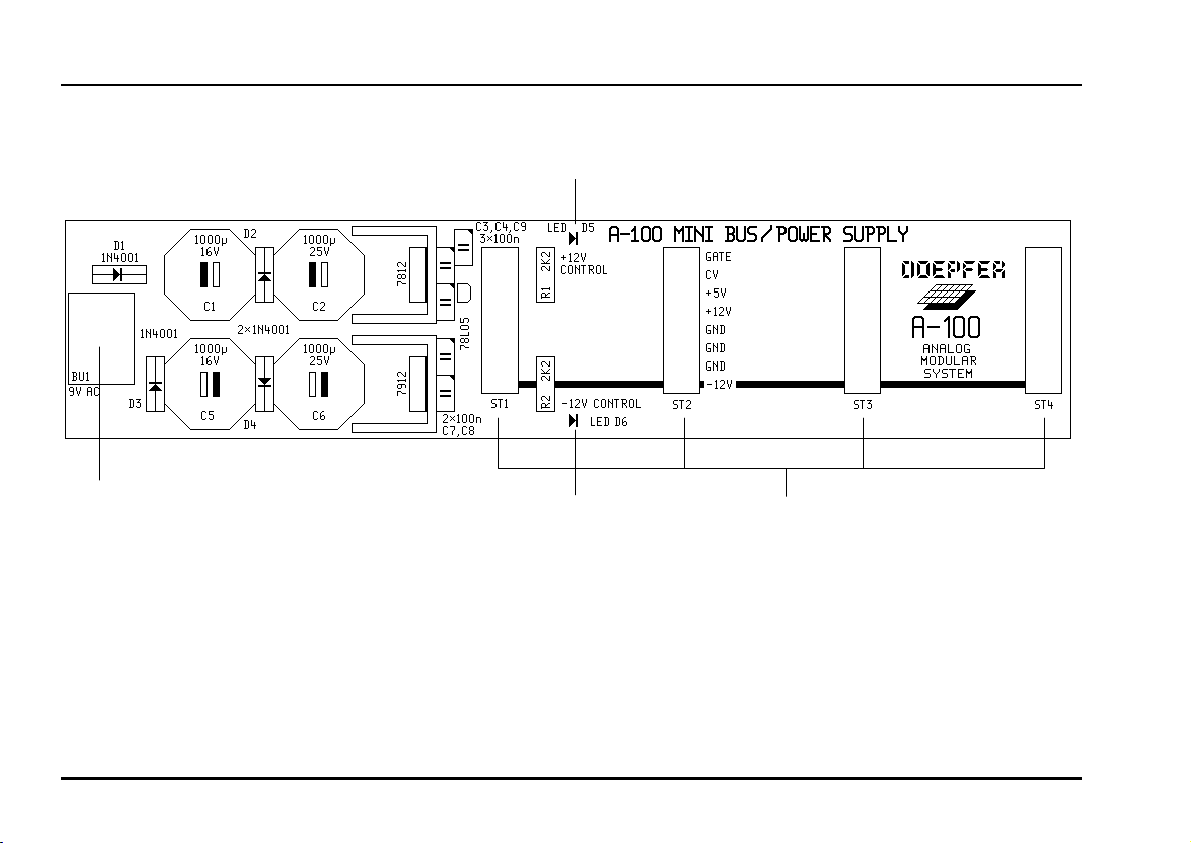
9.3.2. A-100 MNT - Overview
➀
doepfer
Controls:
1 LED : LED indicator for +12 V supply.
2 LED : LED indicator for -12 V supply.
32
➁
In- / Outputs:
! BU 1 : Input for external power supply (7 ...
9 V AC)
" ST 1 ... ST 4 : Bus output sockets for four
modules.
For the new version of the pc board from spring 2007
the positions of the control LEDs are a bit different.
Page 3

doepfer
System A - 100 9. Appendix
9.3.3. Controls / indicators
1 LED • 2 LED
LEDs 1 and 2 indicate that the power supply is
working properly. Once the MNT is connected, both
LEDs should come on.
A
If both LEDs don’t come on, first of all check
that mains power is available at the socket
which the MNT power supply was connected
to; then that the mains adaptor is actually
putting out voltages, and that a DC adaptor
hasn’t been used by mistake. If both these
points are checked, then the MNT must be
defective. The same applies if just one of the
LEDs comes on.
9.3.4. In- / outputs
! BU 1
This is the socket to which the plug from the external
power supply is connected.
" ST 1 ... ST 4
The sockets labelled " on the diagram on p.2 are
where the modules are connected.
So... to connect modules up to the MNT .....
D Disconnect the power supply lead from socket !.
D Connect the ribbon cable supplied with each
module to the module’s bus connector
(see
1
in Fig. 1). As a rule, this is 16-way, but on
some modules it’s only 10-way. Check that the
2
cable connector is oriented correctly, (see
1), and press it on to the module’s bus pins.
A
Be very careful to ensure that the coloured
marking on the ribbon cable is at the bottom
of the module’s connector (see
1) and that the connection is perfect, and
pushed fully home, not at a slight angle.
Failure to check this may result in the module’s instant destruction as soon as the power
is re-connected.
in Fig.
3
in Fig.
33
Page 4

9. Appendix System A - 100
doepfer
3
Bestückungsseite
components side
3
1
Fig. 1: Connecting the ribbon cable to the module
D Now join the free end of the ribbon cable (see
Fig. 2) to the nearest available position on the
system bus board (see
A
Again ensure that the coloured marking on
the ribbon cable is at the bottom of the
module’s connector (see
that the connection is perfect, and pushed
fully home, not at a slight angle. Failure to
check this may again result in disaster.
1
in Fig. 2).
2
3
in Fig. 1) and
2
in
Busplatine
bus board
1
2
Fig. 2: Connecting the ribbon cable to the bus
board.
D Now fix the module solidly in its case.
D Re-connect the A-100 MNT’s power supply, and
then switch on the mains again.
D Test out the newly installed module.
If it doesn’t seem to be working as expected, imme-
diately disconnect the system from the power supply again.
In this case, double-check the connections, making
completely sure that the ribbon cable is the right
way round where it connects to the module and to
the bus.
34
 Loading...