

Page 1
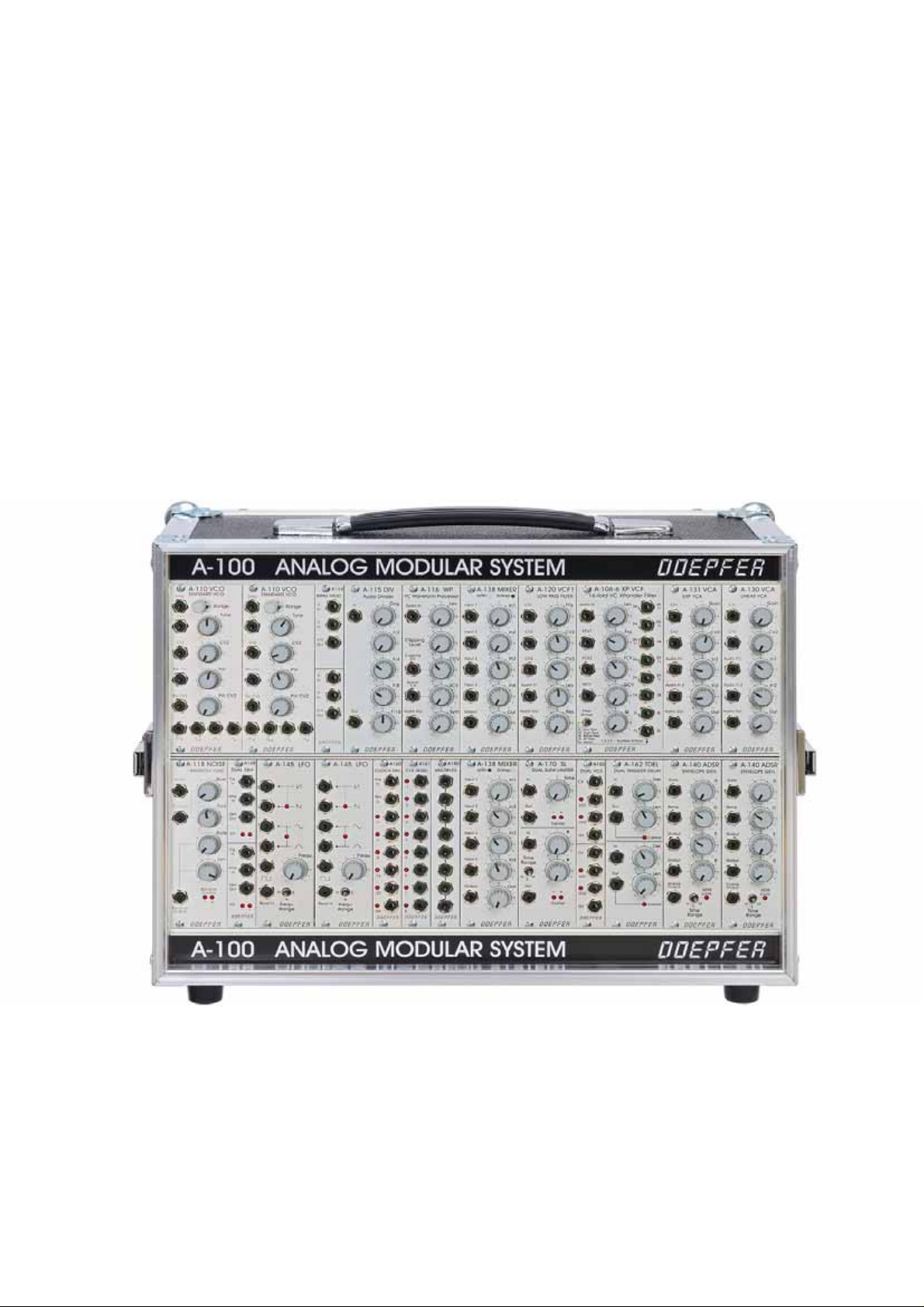
A-100
Analog Modular System
Operating Instructions
doepfer Musikelektronik Gmbh
Page 2

The complete A-100 user's guide is available for download on our website:
www.doepfer.com Æ Manuals Æ A-100 Æ A100_Manual_complete.pdf.
Here you find also the links to user manuals of single modules.
The manual is also available at extra charge in printed form in a ring binder. Please
contact your local dealer if you want to order the printed version of the manual.
More detailed information about electrical and mechanical details of the A-100 is also
available on our website:
www.doepfer.com Æ products Æ A-100 Æ Technical Details
and
www.doepfer.com Æ products Æ A-100 Æ Mechanical Details
The page www.doepfer.com Æ products Æ A-100 also contains links to additional
information around the A-100 system, e.g. complete A-100 module overview, basic
systems, system suggestions or a system planner.
On the FAQ page of our website some special questions have been answered also:
www.doepfer.com Æ FAQs Æ A-100
Package
We recommed to keep the original carton to have available a suitable package for the
return consignment e.g. in case of a repair.
Page 3

E
Warning:
Inside the A-100 cases are dangerous voltages. It is essential to take careful
note of the following safety instructions:
• Before using any part of the instrument, read these instructions and notes
carefully.
•
The instrument may only be used for the purpose described in this operating
manual. Due to safety reasons, the instrument must never be used for other
purposes not described in this manual. If you are not sure about the intended
purpose of the instrument please contact an expert.
•
The instrument may only be operated with the voltage specified near the power
input on the rear panel.
•
Before opening up the case or moving a module or blanking panel,
the mains power supply plug out
. This applies also to removing or replacing any
always take
panel or module.
•
All empty spaces in the rack must be filled with modules or blind panels before the
unit is connected to mains voltage.
•
The instrument must never be operated outdoors but only in dry, closed rooms.
Never use the instrument in a humid or wet environment nor near inflammables.
•
Do not use this instrument in damp environments, or close to water.
•
No liquids or conducting materials must get into the instrument. If this should
happen the instrument must be disconnected from power immediately and be
examined, cleaned and eventually be repaired by a qualified person
•
Do not use this instrument in close proximity to heat sources such as radiators or
ovens. Don’t leave it in direct sunlight.
•
This instrument must be assembled or installed in a way that guarantees sufficient
ventilation and air circulation.
•
The instrument must not be exposed to temperatures above 50°C or below -10 °C.
In use, the instrument must be at a minimum temperature of 10 °C.
•
In case of an A-100G6 case: keep the top side of the instrument free in order to
guarantee proper ventilation, otherwise the instrument could be overheated. Never
place heavy objects on the instrument.
•
This instrument can, without any external amplification or in combination with a
headphone or speaker amplifier, produce sound levels which can damage your
hearing. Don’t work at high sound levels for prolonged periods of time, and don’t
ever use levels which cause discomfort.
•
The instrument’s mains power supply lead should be disconnected if it is not used
for any substantial period. If there is any damage the cables must be repaired or
replaced by an authorized person
•
Do not tread on the mains supply lead.
•
In disconnecting the lead, pull the plug, not the cable.
•
If this instrument is connected to others, check in their manuals for connection
instructions.
Page 4

•
Make particularly sure that no object falls into the instrument, and that no liquid
gets into it.
•
Transport the instrument carefully, never let it fall or overturn. Make sure that
during transport and in use the instrument has a proper stand and does not fall, slip
or turn over because persons could be injured
•
The instrument must be checked and serviced by a qualified technician in the
following cases:
o
the power supply lead or connector is damaged in any way,
o an object or fluid has somehow got into the instrument,
o
the instrument was exposed to rain,
o
the instrument stops working properly or starts to behave erratically,
o the instrument is knocked over or dropped and/or its case is damaged.
•
There are no user-serviceable parts in the instrument. Refer all repairs to
•
All eventual modifications must only be carried out by a qualified person who will
follow the valid safety instructions. Every modification should becarried out only at
the manufacturer or an authorized service company. Any modification not released
by the manufacturer leads to the extinction of the operation permission.
Connecting to the electricity supply
•
The system A-100 must only be connected to the mains voltage that is specified at
the back of the A-100 frame (220 V to 240 V / 50 Hz or 110 to 120 V / 60 Hz).
•
If the fuse has to be replaced only the type of fuse specified at the back of the A100 frame is allowed. If another fuse is used the warranty is void and the A-100
may be damaged. The fuse is located at the mains inlet on the back of the A-100
frame (exception: suitcase version with mains inlet at the front). To replace the fuse
one has to disconnect the mains cable and remove the fuse holder (e.g. with the
aid of a screw driver). The fuse holder is a small black plastic part that is inserted
into the mains inlet.
•
The following table shows the fuse values for different kind of cases:
Page 5

Case Version Mains Voltage
A-100G3 19" frame old version
(with 650 mA power supply A-
100NT12)
A-100G6 19" frame old version
(with 650 mA power supply A-
100NT12)
A-100G3 19" frame 3U/84HP
A-100G6 19" frame 6U/84HP
A-100P6 suitcase version 6U/84HP
A-100P9 suitcase version 9U/84HP
A-100LC6 low cost suitcase 6U/84HP
A-100LC9 low cost suitcase 9U/84HP
A-100LCB low cost base frame 2 x
3U/84HP
A-100PMS6 monster suitcase
6U/128HP
A-100PMS9 monster suitcase
9U/128HP
A-100PMS12 monster suitcase
12U/128HP
A-100PMB monster base frame
2x3U/128HP
Mains Voltage
230V
125 mA 250 mA
400 mA 800 mA
400 mA
400 mA
400 mA
400 mA
400 mA
400 mA
400 mA 800 mA
800 mA
800 mA 1.6A
1,6 A
800 mA
115V
800 mA
800 mA
800 mA
800 mA
800 mA
800 mA
1.6A
3.15 A
1.6 A
grey marked
The
completeness.
In any case
of response is abbreviated by a character on the metallic ring of the fuse: F (
m
(
edium) or T (time lag = slow blow). A fuse coded "T" has to be used ! Medium or
fast fast fuses are unsuitable and will blow. The reason for the time lag fuses is the
high transient current during power on that is ignored by the slow fuses. This transient
current is much higher for ring core/toroid transformer than for normal transformers. If
you still own an older A-100 frame or suitcase with the old version of the power
supply (A-100NT12, 650mA output current, manufactured until about 2001) a fuse
with 125 mA (230V) / 250 mA (115V) is required.
time lag (slow blow) fuses
cases are no longer available but have been added for the sake of
5x20 mm have to be used ! Usually the type
f
ast), M
Page 6

Even the A-100 DIY kits contain fuses. There is no difference between 115V and
230V for the fuse values as these fuses are used to protect the secondary circuits of
the supplies (i.e. the low voltages). The specified values are valid for the transformers
and wall outlet power supplies that are available from us for the DIY kits. If other
transformers or supplies are used the values have to be changed depending on the
specification of the transformer or supply. In this case the values specified in the table
are maximum values. If a transformer or supply with lower power is used the fuse
values should be changed according to the specification of the transformer or supply.
Type kit Fuse (5x20mm)
A-100 DIY #1
A-100 DIY #2
2500mA/2.5A träge / 2500mA/2.5A time lag (slow blow)
2 x 500mA/0.5A träge / 2 x 500mA/0.5A time lag (slow blow)
The grey marked DIY kit is no longer available but has been added for the sake of
completeness.
Installation
•
Do not expose the A-100 to rain or moisture.
•
Operation is allowed only in a dry environment in a closed room but not in the open
country.
•
The installation near a large amplifier or other equipment which uses powerful
mains transformers may cause hum.
•
Do not install the A-100 in close proximity to equipment which produces an
electromagnetic field (monitors, computers, etc.), to avoid the possibility of mutual
interference.
•
Do not connect the A-100 to a socket or outlet which is also being used by
equipment such as electric motors, lighting dimmers, etc, which can cause
interference. Use a separate outlet for the A-100.
•
Use in a dusty environment should be avoided.
Care and maintenance
•
Apart from cleaning the instrument, no other usermaintenance is recommended, of
the modules or system busses. Internal maintenance should be carried out only by
qualified technicians.
•
For regular cleaning, use a soft, dry, or slightly damp cloth. To remove dirt, if
necessary, use a cloth slightly moistened with a very diluted mild detergent. This
should be more than sufficient to clean the instrument. Never use solvents like
petrol, alcohol, or thinners.
Page 7

Mechanical and electrical conception
The modular system consists of a case (e.g. 19" case A-100G6 or one of the suitcase
versions A-100P6/P9 or one of the low-cost cases A-100LC6/LC9/LCB or one of the
"monster" cases A-100PMS6/PMS9/ PMS12/PMD12/PMB) and the modules that are
installed into the case in question.
Each case contains one or more bus A-100 boards. The modules are connected to
the bus boards via ribbon cables. The bus is used to supply the modules with the
required supply voltages. For some modules the bus board can be used also to carry
the CV and the Gate signal (for details please refer to the user manuals of the
modules in question).
Important note
boards or 100% compatible
allowed to use bus boards with polarized pin headers (bowl pin headers with code
gap). These may force the user to connect the bus cable in a direction which might be
the wrong one ! This will destroy the module and the warranty is void ! In the A-100
the colored wire of the ribbon cable marks -12V and this wire has to point to the
bottom under all conditions !
Each case contains also one or more power supplies. The power supply provides the
supply voltages +12V and –12V that are required to run the A-100 modules. A few
modules also require +5V (e.g. A-190-1 and A-113). In these cases the +5V adapter
A-100AD5 is recommended. Each power supply (A-100PSU2) provides max. 1200
mA. Until about 2001 a smaller supply with 650 mA only was used. When a system is
planned the sum of all module currents has to be less than the max. current of the
power supply.
The cases A-100G6/P6/P9/LC6/LC9/LCB have one A-100PSU2 available and can be
used for modules with a total current of 1200mA or less. With the exception of a few
very "exotic" module sets this is sufficient for all reasonable module combinations.
The cases A-100PMS6/PMS9/PMB have two A-100PSU2 available which means that
modules up to 2400 mA total current can be installed. Case A-100PMS12 contains
four A-100PSU2 corresponding to 4800 mA.
: A-100-modules have to be connected only to original A-100 bus
bus boards of other manufacturers ! Particularly it's not
Page 8

Installing modules
•
To be on the safe side please calculate the total current requirement of existing
modules plus the new module/s.
•
Check that this total is less than 1200 mA (or 2400 mA or 4800 mA depending
upon the A-100 case that is used). Normally this will apply.
•
If that's OK: First of all, take the A-100’s plug out of the wall socket.
•
Check if each module is equipped with a ribbon cable with a 16 pin female
connector at the open end. The ribbon cable can be 10 or 16 pin but the female
connector has to be 16 pin !
•
Now join the free end of the ribbon cable to the nearest available position on the
system bus board
•
For this one has to plug the female 16 pin connector at the free end of the ribbon
cable to one of the pin headers of the bus (these are also 16 pins). Use a pin
header of the bus board that is close to the position where the module has to be
mounted later.
•
Check very carefully that it is connected so that the
coloured marking
on the
ribbon cable is at the bottom of the bus connector. The coloured marking has to
align with the "-12V" printing on the bus board next to the pin header.
•
Check also very carefully that it is
not vertically or horizontally displaced .
•
Failure to check this may result in the module’s instant destruction as soon as the
pushed fully home, not at a slight angle and
power is turned back on!
•
When you’re installing extra modules, it may be necessary to take another module
or two out, to allow you easier access to the bus board.
•
Place the module carefully into the space in the rack, and fasten it firmly in place
with the supplied screws (M3x6).
•
Repeat this procedure until all modules (and possibly blind panels) are installed
and the front of the A-100 case is fully closed.
•
Now plug the system A-100 back into the main power supply, and switch it on.
•
Test out the newly installed modules.
•
If it doesn’t seem to be working as expected, immediately disconnect the system
from the power supply again.
•
In this case, double-check all connections, making completely sure that the ribbon
cables are the right way round where they connect to the bus.
Interconnecting modules
For connecting modules to each other, you need mono mini-jack ( 3.5 mm) patch
leads
. We offer patch leads in different lengths (from 15 cm to 2 m) and colors.
 Loading...