

Page 1

ChemLogic® 4 & 8
Continuous Gas Monitor User Manual
Page 2

2
DC-ITD-CL4andCL8MAN01.A www.dodtec.com
NOV 2018 815-788-5200
CL4 & CL8 Manual
© DOD Technologies, INC
675 Industrial Drive Bldg. A.
Cary, IL 60013
Phone 815.788.5200 • Fax 815.788.5300
Page 3

3
DC-ITD-CL4andCL8MAN01.A www.dodtec.com
NOV 2018 815-788-5200
CL4 & CL8 Manual
EC DEC LAR AT ION OF CO NFO RM ITY
EU DEC LAR AT ION OF CO NFORM ITY
DOD TECHNOLOGIES INC.
675 Industrial Drive – Bldg. A
Cary, IL 60013
USA
Name and address of the company established in European Community and authorized to compile
the Technical File
:
ACC - Services Contact
105 route des pommiers
Centre Ubidoca
74370 St Martin Bellevue
France
DOD TECHNOLOGIES INC. declares under our sole responsibility that the product described as:
Equipment Name: Continuous Gas Monitor
Equipment Description: Detection and measurement of toxic gases
Model: CL4/CL8
Serial number(s): _______________
Complies with the requirements of the following European Directives:
Machinery Directive 2006/42/EC;
Electromagnetic Compatibility Directive 2014/30/EU.
RoHS Directive 2011/65/EU.
Main standards considered :
EN ISO 12100 :2010.
EN 50271: 2010.
EN 60204-1:2006 +A1:2009.
EN 50270: 2006.
EN 50581: 2012
Name of authorized company representative: Mr. Daniel O’Donnell
President
DOD Technologies, INC
Daniel O’Donnell
Daniel O'Donnell
Date: 05/25/18
At: Cary, Illinois USA
Page 4

4
DC-ITD-CL4andCL8MAN01.A www.dodtec.com
NOV 2018 815-788-5200
CL4 & CL8 Manual
Table of Contents
Chapter 1 – Overview .................................................................................................................................................................... 7
1.1 Introduction ........................................................................................................................................................................... 7
1.2 Sampling and Monitoring ..................................................................................................................................................... 7
1.3 Flow Connections ................................................................................................................................................................. 7
1.4 Electrical Connections .......................................................................................................................................................... 8
1.5 Theory of operation .............................................................................................................................................................. 8
1.6 Time Weighted Average (TWA) ............................................................................................................................................ 8
Chapter 2 – Features ..................................................................................................................................................................... 9
2.1 External Layout ..................................................................................................................................................................... 9
2.1.1 Warning Labels, Descriptions, & Danger Zones .............................................................................................................. 9
2.1.2 ChemLogic 4 & 8 Danger Zones ..................................................................................................................................... 10
2.1.3 Status Lamp (OPTIONAL) ............................................................................................................................................... 11
2.1.4 Output Wiring Knockouts ................................................................................................................................................ 11
2.1.5 Touch Screen Display...................................................................................................................................................... 11
2.1.6 Keyed Service Door Access ............................................................................................................................................ 11
2.1.7 A/C Power & Switch ......................................................................................................................................................... 11
2.1.8 Flow Adjustment .............................................................................................................................................................. 11
2.1.9 ChemLogic Paper Tape ................................................................................................................................................... 11
2.1.10 Maintenance door.......................................................................................................................................................... 11
2.1.11 Take-up reel ................................................................................................................................................................... 12
2.1.12 Tubing Connections ...................................................................................................................................................... 12
2.2 Maintenance area ............................................................................................................................................................... 12
2.3 Internal Layout – Service area ........................................................................................................................................... 12
2.4 Password Security .............................................................................................................................................................. 13
2.5 USB Memory Stick .............................................................................................................................................................. 14
Chapter 3 – Installation ............................................................................................................................................................... 15
3.1 Selecting a location ............................................................................................................................................................ 15
3.1.1 Lifting Instructions .......................................................................................................................................................... 15
3.2 Mounting ............................................................................................................................................................................. 17
3.3 Sample Tubing .................................................................................................................................................................... 19
3.3.1 Sample Manifold Relocation ........................................................................................................................................... 19
3.3.2 End of line particulate filters ........................................................................................................................................... 19
3.4 Exhaust tubing .................................................................................................................................................................... 20
3.5 A/C Power ............................................................................................................................................................................ 20
3.6 Output Wiring ...................................................................................................................................................................... 20
Page 5

5
DC-ITD-CL4andCL8MAN01.A www.dodtec.com
NOV 2018 815-788-5200
CL4 & CL8 Manual
3.6.1 Standard Output Relay Module Wiring ........................................................................................................................... 20
3.6.2 Optional 4 to 20ma Output Module Wiring .................................................................................................................... 22
3.6.3 Optional 8 Point Relay Module (Item #2-500-012) ....................................................................................................... 22
Chapter 4 - Setup & Configuration .............................................................................................................................................. 23
4.1 Set system date and time .................................................................................................................................................. 23
4.2 Gas Selection ...................................................................................................................................................................... 23
4.3 Alarm Settings..................................................................................................................................................................... 23
4.4 Output Relays ...................................................................................................................................................................... 23
4.5 Concentration Logging ....................................................................................................................................................... 23
4.6 Install new tape ................................................................................................................................................................... 23
4.7 USB Memory Stick .............................................................................................................................................................. 24
4.8 Setup Complete ................................................................................................................................................................... 24
Chapter 5 – Basic Operation ....................................................................................................................................................... 25
CL4/CL8 Menu Overview .......................................................................................................................................................... 25
5.1 Initialization ......................................................................................................................................................................... 25
5.2 Setup / Main Menu ............................................................................................................................................................. 26
5.2.1 Gas & Alarm Settings Menu ............................................................................................................................................ 27
5.2.2 Set Date/Time .................................................................................................................................................................. 27
5.2.3 Load Tape ......................................................................................................................................................................... 28
29
5.2.4 Flow Adjustment .............................................................................................................................................................. 29
5.2.5 Calibration Factors .......................................................................................................................................................... 30
5.2.6 Set & Test Outputs ........................................................................................................................................................... 31
5.2.7 Factory Settings ............................................................................................................................................................... 32
5.2.8 Event History .................................................................................................................................................................... 32
5.3 Concentration Log .............................................................................................................................................................. 33
5.3.1 Concentration Configuration .......................................................................................................................................... 33
5.4 Analysis Mode ..................................................................................................................................................................... 34
5.5.1 Point Detail screen .......................................................................................................................................................... 35
5.5 USB Memory Stick log ........................................................................................................................................................ 35
5.6 Time Weighted Average (TWA) .......................................................................................................................................... 36
Chapter 6 – Maintenance ............................................................................................................................................................ 38
6.1 Maintenance Door Access ................................................................................................................................................. 38
6.2 Service Door Access ........................................................................................................................................................... 38
6.3 ChemLogic Paper tape ....................................................................................................................................................... 38
ChemLogic Paper Tape Installation Procedure ...................................................................................................................... 39
6.4 End of line particulate filters .............................................................................................................................................. 40
6.5 Flow adjustment ................................................................................................................................................................. 41
Page 6

6
DC-ITD-CL4andCL8MAN01.A www.dodtec.com
NOV 2018 815-788-5200
CL4 & CL8 Manual
6.6 USB Memory Stick replacement ........................................................................................................................................ 41
6.7 Apply grease periodically ................................................................................................................................................... 42
6.8 Fuse Replacement .............................................................................................................................................................. 42
Chapter 7 – Service & Support .................................................................................................................................................... 43
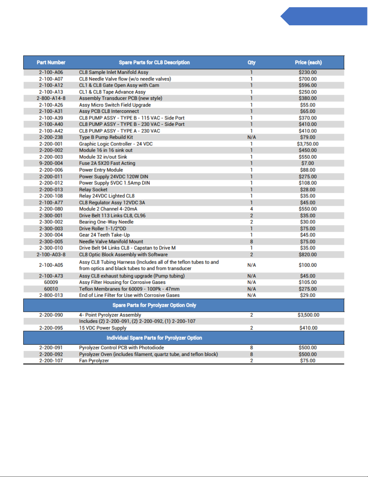
Appendix A – Accessories / Cassettes ...................................................................................................................................... 44
Appendix B – I/O Connection Detail ........................................................................................................................................... 46
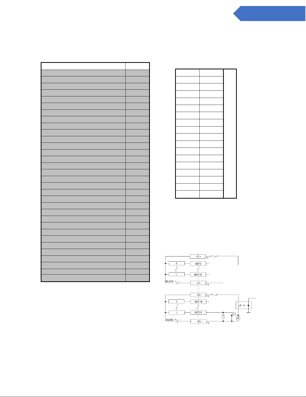
B.1 Standard Output Relay Module ......................................................................................................................................... 46
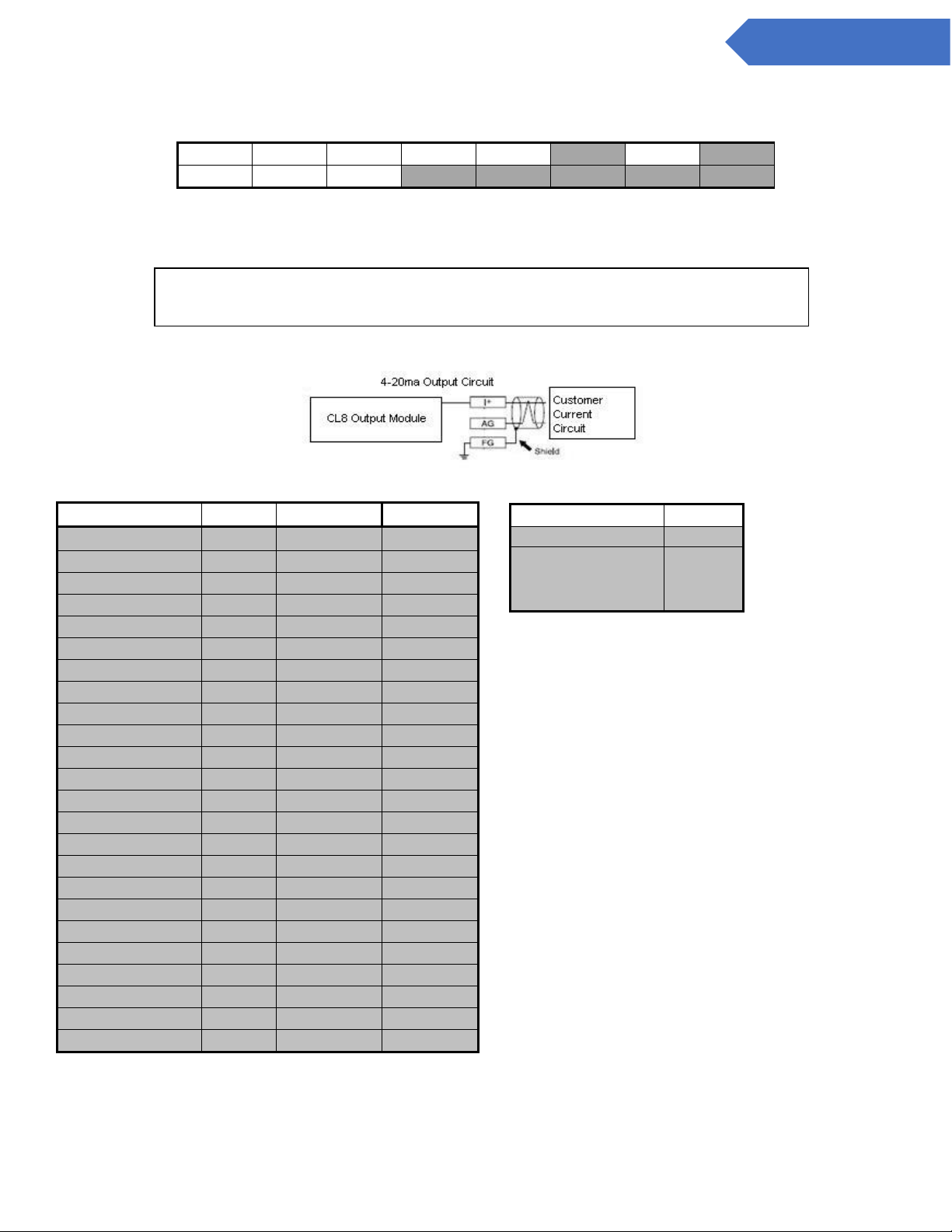
B.2 4 to 20mA Module (2 Points per Module) (PN: 2-500-011) ...................................................................................... 47
B.2.1 4 to 20mA Module (4 Points per Module) (PN: 2-500-011) ................................................................................... 48
B.3 8-Point Module (PN: 2-500-012) ...................................................................................................................................... 49
B.4 Optional Mechanical Relays .............................................................................................................................................. 50
B.4.1 Optional Mechanical Relay Wiring ................................................................................................................................. 51
B.5 OPC Interface (PN: 2-500-501) ......................................................................................................................................... 53
Appendix C – System Specifications ......................................................................................................................................... 54
Appendix D – System Event Messages ...................................................................................................................................... 55
Appendix E – Gas Specifications ................................................................................................................................................ 57
Appendix F – USB Memory Stick Data ....................................................................................................................................... 59
F.1 Alarm & Event files (ZG*.CSV) ............................................................................................................................................ 59
F.2 TWA Data Logs (TYYMMDD.CSV) ..................................................................................................................................... 60
F.3 Concentration Log Files (ZL*.CSV) .................................................................................................................................... 60
F.4 Config File ............................................................................................................................................................................ 61
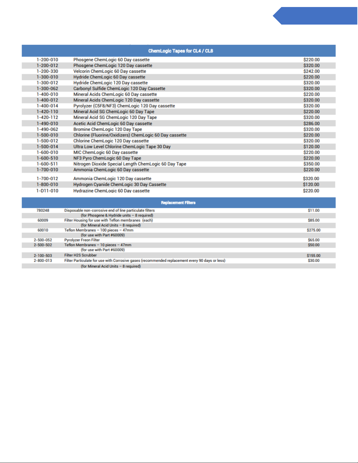
Appendix G – ChemLogic Cassettes .......................................................................................................................................... 62
Appendix H – Optic Block Cleaning Procedure ......................................................................................................................... 63
H.1 Basic Optics Cleaning ........................................................................................................................................................ 63
H.2 Advanced Optics Cleaning ................................................................................................................................................. 64
Page 7

7
DC-ITD-CL4andCL8MAN01.A www.dodtec.com
NOV 2018 815-788-5200
CL4 & CL8 Manual
Chapter 1 – Overview
1.1 Introduction
WARNING:
Operation of the ChemLogic 8 continuous gas detection system without a manual in the native language in
its country of operation is illegal. A translated copy of the manual should be requested immediately from DOD
Technologies and before installation of the device. Failure to do so may result in severe injury.
Contact:
Phone: +1 815-788-5200
email: [email protected]
The ChemLogic 4 (CL4) & 8 (CL8) continuous gas detection systems should be used exclusively for the quick
detection of toxic, corrosive, and asphyxiant gases for process measurement and personnel safety purposes.
Failure to comply with the intended purpose of the device may result in injury or death.
The DOD Technologies ChemLogic 4 (CL4) ChemLogic 8 (CL8) simultaneously monitors eight locations
(called points)
for toxic and corrosive gases. It responds to gases that exceed a programmed alarm level by:
• Triggering visual alarms that warn of high or low concentrations
• Triggering relays or activating analog outputs to external devices
• Displaying the point number, gas type, and gas concentration
• Recording the alarm information and storing it in memory
The CL/4CL8 triggers relays for each individual point for two levels of gas concentrations. These
programmable limits are factory-set at 1 TLV and 2 TLV for their respective gases.
Each point may be up to 300 feet (91.44 m) from the CL4/CL8 location. This allows operators to monitor gas
concentrations in an area removed from the location where gas may actually be leaking.
The CL4/CL8 provides a fast response to a wide range of gases. It was designed for maximum uptime, so
routine maintenance and service can be performed quickly and easily.
The CL4/CL8 uses DOD Technologies ChemLogic paper tape technology for fast and accurate gas detection.
1.2 Sampling and Monitoring
The system draws sample flow simultaneously from all eight points. Part of the sample flow is diverted
across the ChemLogic tape. All 4/8 channels exhaust through a single port. The ChemLogic 4/8 continuous
gas detection system operates at a noise level below 70 dB(A) and does not require hearing protection for
operation or work within close proximity. Workplace environment outside the ChemLogic 4/8 system may still
require hearing protection. Please consult your safety officer for your recommended safety protocols.
1.3 Flow Connections
Flow connections consist of “quick-connect” ports on the top or side of the CL4/CL8 UNIT. There are eight
inlets, one for each monitored point, and an exhaust outlet.
Page 8
8
DC-ITD-CL4andCL8MAN01.A www.dodtec.com
NOV 2018 815-788-5200
CL4 & CL8 Manual
1.4 Electrical Connections
“Knockout panels” for external electrical connections are provided on the top or right side of the CL4/CL8.
The covers are exchangeable to provide top or right-side flexibility.
1.5 Theory of operation
The system draws sample flow simultaneously from all four/eight points. Part of the sample flow is diverted
across the ChemLogic Tape. The ChemLogic 4/8 uses an advanced optical detection system to measure the
light level reflected from the ChemLogic tape. As the target gas is detected, the color of the of the ChemLogic
tape changes. This color change results in a loss of reflected light across the ChemLogic tape. This loss of
reflected light is detected by the advanced optics system in the ChemLogic 4/8. The ChemLogic 4/8 will then
report an appropriate gas concentration reading and/or a gas alarm.
1.6 Time Weighted Average (TWA)
During analysis the CL4/CL8 stores the TWA information every 8 hours* (referred to as a ‘cycle’). The
system retains the 5 most recent cycles in memory and will save all cycles to the CUSB Memory Stick – if
installed. The number of cycles capable of being stored on the USB Memory Stick is only limited by the size
of the USB Memory Stick.
*NOTE: If analysis is stopped by the operator or due to any other factor (critical
service fault, power interruption, etc.), the TWA information is saved as a
separate cycle regardless of how much time has elapsed since the cycle started.
Page 9
9
DC-ITD-CL4andCL8MAN01.A www.dodtec.com
NOV 2018 815-788-5200
CL4 & CL8 Manual
Chapter 2 – Features
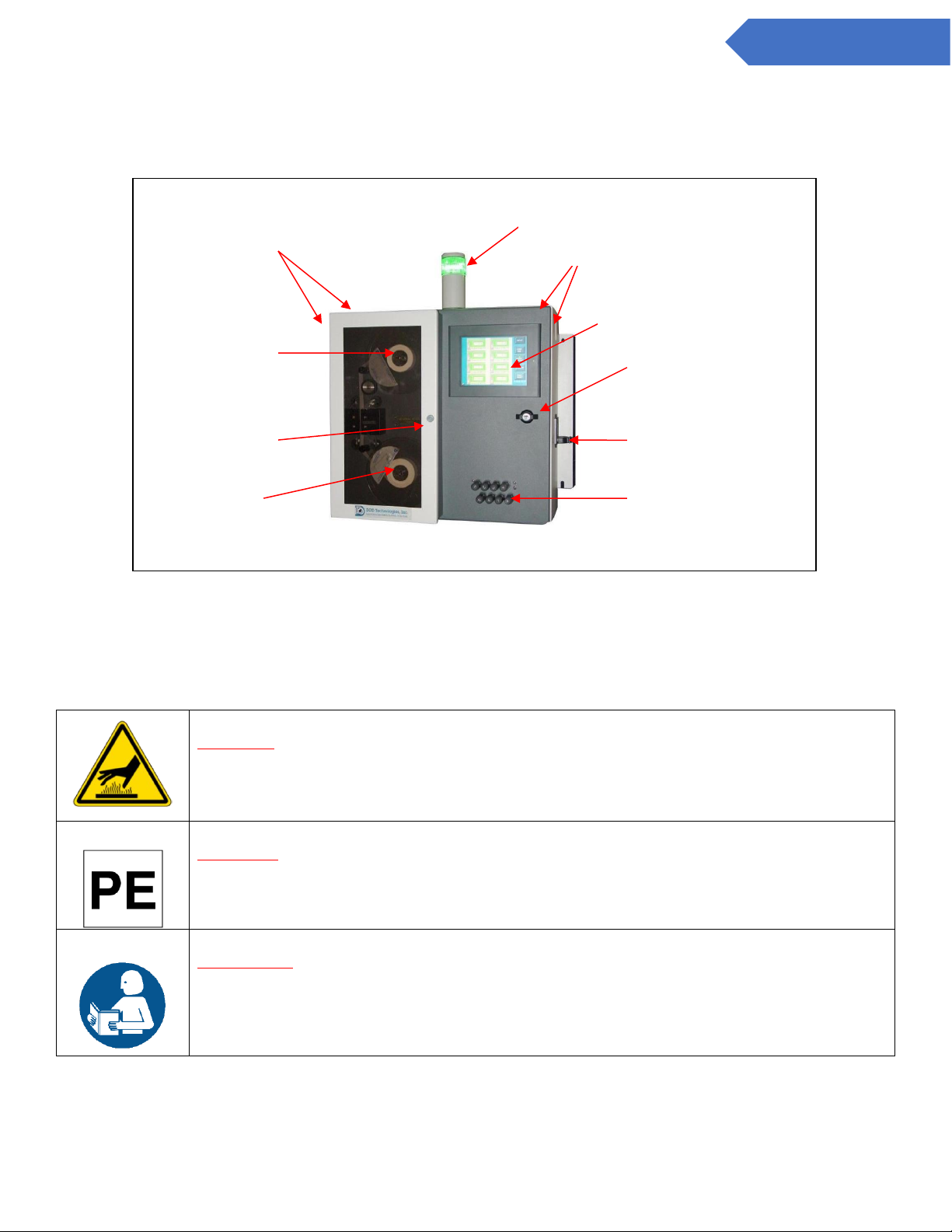
2.1 External Layout
Figure 2.1
2.1.1 Warning Labels, Descriptions, & Danger Zones
The below table references all warning labels and their meanings that may be encountered while operating
and servicing the ChemLogic 4 and 8 continuous gas detection equipment.
WARNING:
Hot Surface. This surface will be hot to touch and may cause injury. Please avoid or take
caution when working near this zone.
WARNING:
Protective Earth Ground. Terminal Intended for connection to external conductor for
protection against electric shock in case of fault.
ATTENTION:
Please read operators manual for all instruction for this machine. If manual is not in
country’s native language, requested updated manual before use of equipment.
Output Wiring Knockouts
Keyed Service Door Handle
A/C Power & Switch
Flow adjustment knobs
ChemLogic Tape
Maintenance Door
Take-up reel
4 color status lamp and
audible alarm (Optional)
Flow tubing & exhaust
quick connect system
Touch Screen LCD Display
Page 10
10
DC-ITD-CL4andCL8MAN01.A www.dodtec.com
NOV 2018 815-788-5200
CL4 & CL8 Manual
WARNING:
Electric Shock is possible, please use caution when accessing this zone.
WARNING:
Moving Parts and Hand Crushing possible. Please watch hand placement when working
near this zone.
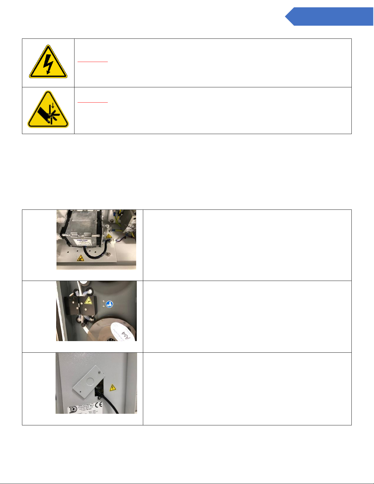
2.1.2 ChemLogic 4 & 8 Danger Zones
Please be aware of the following danger zones on the ChemLogic 4 and 8 continuous gas detection
equipment. Each zone contains warning labels for operator safety. Label meanings/descriptions can be found
in the above table
A
This danger zone is in the service access point of the unit. Users
should be aware of hot surfaces and electrical shock.
B
This danger zone is located on the gate assembly. During
operation, operators could pinch fingers if not aware of hand
placement.
C
This danger zone is located on the right exterior of the unit. This
area warns of electrical shock areas within the service door of the
machine.
Page 11

11
DC-ITD-CL4andCL8MAN01.A www.dodtec.com
NOV 2018 815-788-5200
CL4 & CL8 Manual
2.1.3 Status Lamp (OPTIONAL)
The optional status lamp consists of 4 colored lights – Red, Orange, Blue, and Green along with an audible
alarm. See Appendix A for ordering information.
2.1.4 Output Wiring Knockouts
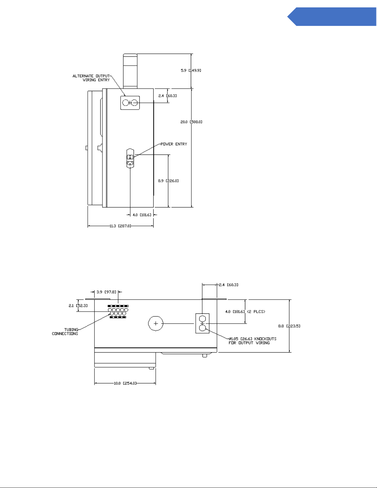
There are two knockouts available for output wiring located on the top panel near the right side and on the
right-side panel near the top.
2.1.5 Touch Screen Display
The CL8 uses a full color touch panel LCD display. All menus and data entry are accomplished by touching
the appropriate area of the screen – see Chapter 5 “Basic Operation”.
2.1.6 Keyed Service Door Access
The door uses a key lock to restrict internal access. See section 2.3 for detailed information on the service
area.
2.1.7 A/C Power & Switch
A/C power is connected on the right-side panel with a standard cable. The on/off power switch is located
adjacent to the power cable connection.
2.1.8 Flow Adjustment
Flow adjustments for all 4/8 points are located on the front panel. Refer to section 5.2.d regarding flow
adjustment.
2.1.9 ChemLogic Paper Tape
ChemLogic paper tapes are accessed by opening the maintenance door. Refer to section 6.3 regarding tape
installation/replacement.
2.1.10 Maintenance door
The maintenance door allows easy access to the ChemLogic tape for installation and replacement.
IMPORTANT: The maintenance door should remain closed and latched except
when changing the ChemLogic tape. Do not open the door while in Analysis
Mode.
Page 12
12
DC-ITD-CL4andCL8MAN01.A www.dodtec.com
NOV 2018 815-788-5200
CL4 & CL8 Manual
2.1.11 Take-up reel
An empty take-up reel is inserted at the time of ChemLogic tape installation (see section 6.3). During
installation the previous take-up reel which is full is removed from CL4/CL8 and discarded. The previous
ChemLogic tape reel which is now empty should then be used as the next take-up reel.
2.1.12 Tubing Connections
Sample tubing and exhaust use a quick connection system for simple installation. The connections may be
made on either the top or left side of the CL4/CL8. See section 3.3 for information on connecting the sample
and exhaust tubing. See also Appendix C for essential information on transport times for gas from sampling
point to the CL4/CL8.
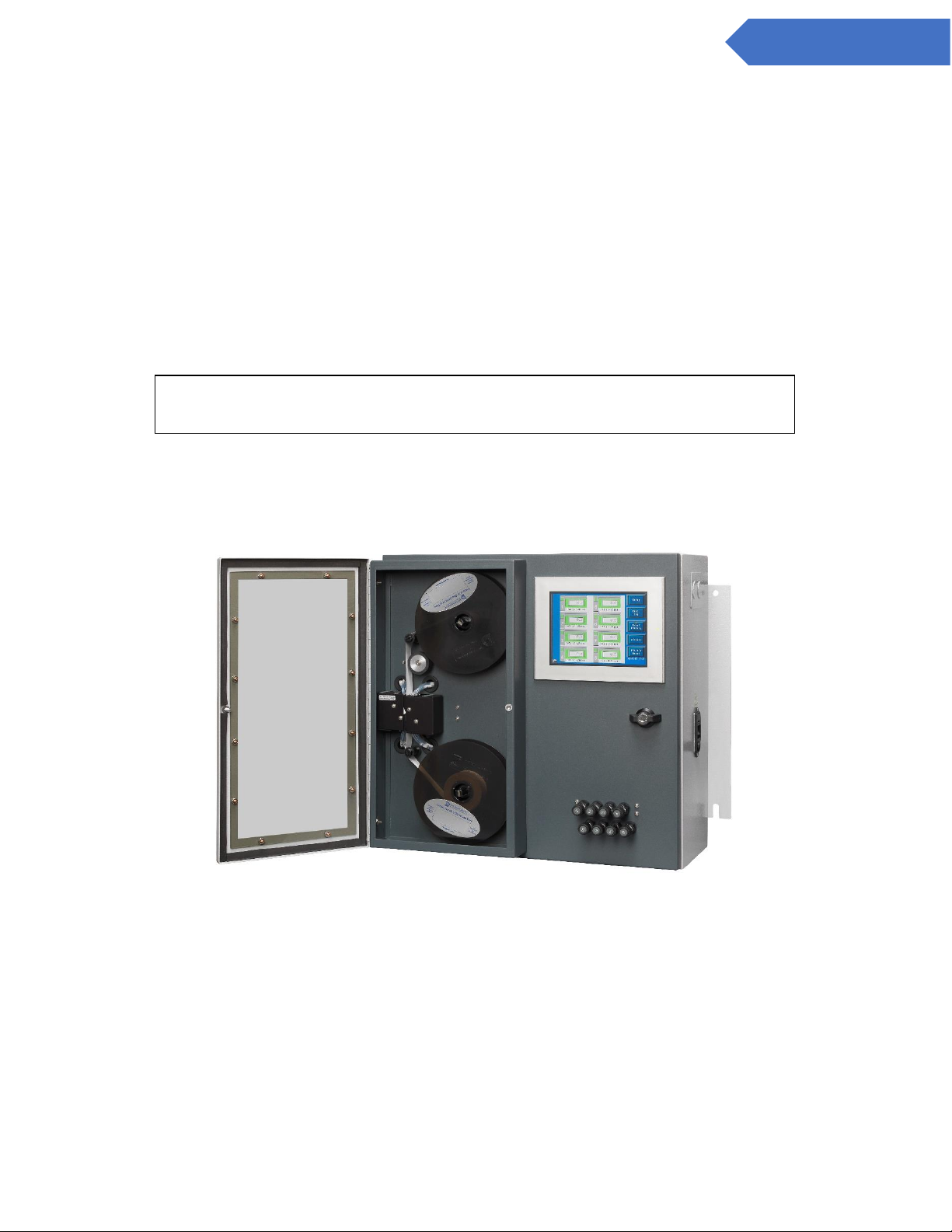
2.2 Maintenance area
The maintenance area allows easy access for changing ChemLogic tape in the CL4/CL8. Figure 2.2 shows
the internal layout with the access panel open. See section 3.5 for tape installation.
Figure 2.2
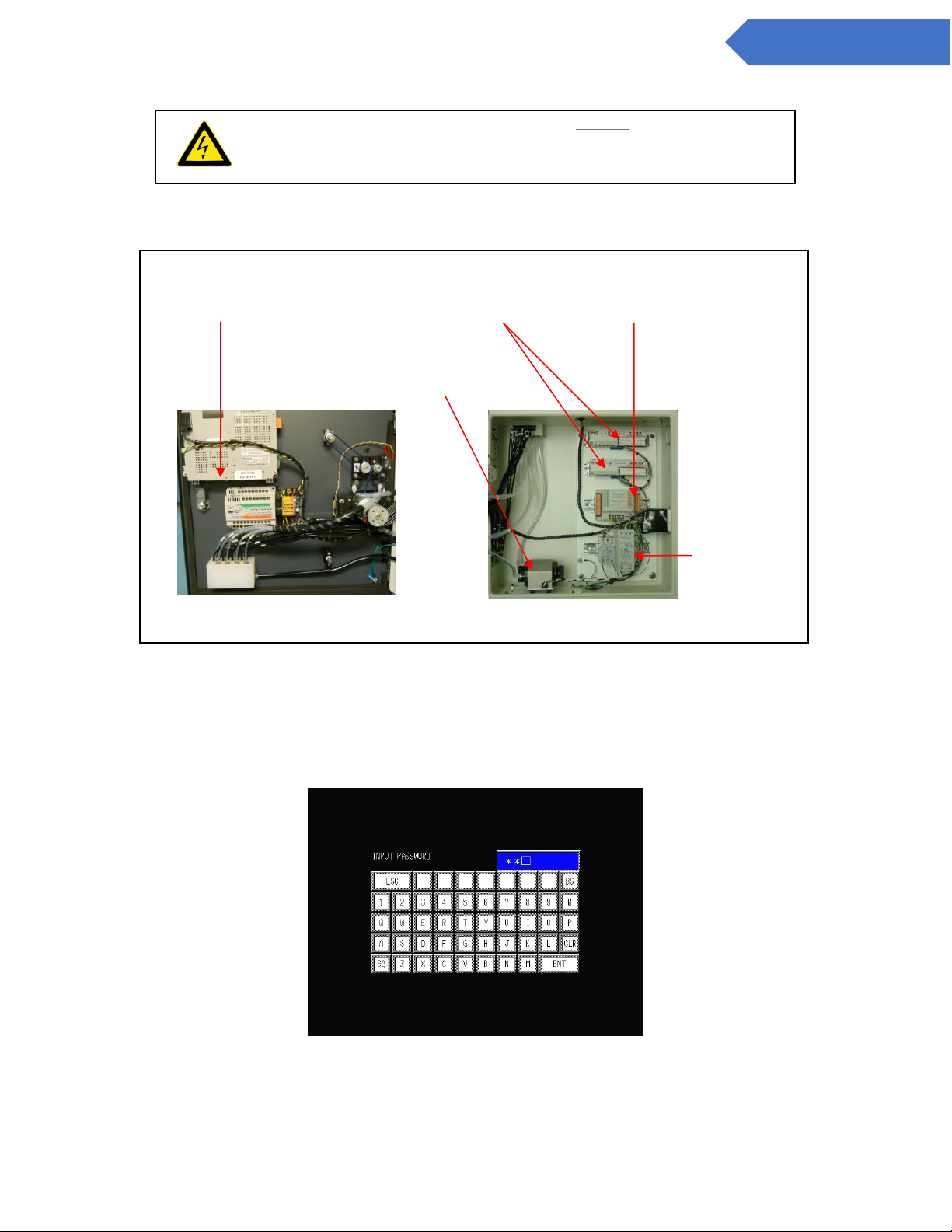
2.3 Internal Layout – Service area
Internal access to the CL4/CL8 for installation and service uses the keyed handle located on the right side of
the front panel. Figure 2.3 shows the internal layout of the CL4/CL8 with the service door open.
IMPORTANT: End of line filters are required at all times on each channel – see
Section 6.2.
Page 13
13
DC-ITD-CL4andCL8MAN01.A www.dodtec.com
NOV 2018 815-788-5200
CL4 & CL8 Manual
The door should be opened by trained service personnel (See section 6.2 )
Figure 2.3
2.4 Password Security
Access to many of the features is controlled through password protection which is entered through the
screen displayed in figure 2.4.
Figure 2.4
DANGER: Turn off the unit and disconnect unplug A/C power to the
unit before opening the Service Door.
Inside w/Service Door open
Back of Service Door
(OPTIONAL) 4-20ma
Output Connection
USB Memory Stick Access
Pump
Power Supply
Page 14

14
DC-ITD-CL4andCL8MAN01.A www.dodtec.com
NOV 2018 815-788-5200
CL4 & CL8 Manual
Whenever someone attempts to access a screen that is password protected, the screen shown in figure 2.2
will appear (see important note below). Several of the setup & configuration screens of the CL4/CL8 require
entry of an administrative password. Factory service screens require entry of a service password - see
section 7.
NOTE: The Administrative Password is included on the first page of this manual. It is suggested that you
remove the page and keep in a safe and secure place. If you forget or lose your password please contact
DOD Technologies, INC. See Chapter 7 for contact information.
2.5 USB Memory Stick
The CL4/CL8 uses a USB Memory Stick to store historical information including concentration logging, event
history, configuration information, and TWA data. The use of higher speed USB Memory Stick (2x, etc.) may
not be compatible with the CL4/CL8. USB Memory Sticks may be purchased through DOD Technologies – see
Appendix A.
IMPORTANT: Once a password is entered it remains active for 2 minutes after
entry so that it does not need to be repeatedly entered when switching between
screens. Please remember that anyone using the touch screen may access
restricted screen locations during this time if the machine is left unattended.
Page 15

15
DC-ITD-CL4andCL8MAN01.A www.dodtec.com
NOV 2018 815-788-5200
CL4 & CL8 Manual
Chapter 3 – Installation
3.1 Selecting a location
The CL4/CL8 should be placed in a location as central as possible to the locations being monitored while
considering the following restrictions:
• The maximum sample line length is 300 ft. Using the shortest possible sample line length will reduce
transport times and increase the response time of the CL4/CL8.
(see Appendix C)
• A/C power is required to the unit.
• Locate near proper ventilation keeping in mind the maximum length of the exhaust
• tubing is 25ft.
• The CL4/CL8 requires stable temperature and humidity levels within range to operate properly.
Recommendations
Do not place in a location which will expose the CL4/CL8 to moisture, dust, corrosive gas, or any unusual
environmental conditions which could damage the unit and/or cause it to operate inaccurately.
3.1.1 Lifting Instructions
It is recommended that installation of this unit requires the help of 3 individuals. Two individuals should lift
the unit into its desired location while the third person secures the device into a mounted position. If the
device must be manually handled, follow the following steps each time:
1. Size up the Load
• Check if the weight of the object is listed on it
• If not, push, pull, gently kick or rock the object to be moved before you attempt to move it – get a feel
for its weight, size and shape
• Check whether the weight is evenly distributed
• Recognize what your own limits are and stick to these limits
Ensure the area is clear
• Work out where the load is going
• Ensure that your intended pathway is clear and free of obstacles
• Make sure that your vision will not be blocked when moving large objects
Position your feet correctly
• Place your feet a comfortable distance apart (shoulder width). A broader base of support increases
stability. With a narrow base of support with your feet too close together, you are more likely to lose
your balance.
• Point your feet in the direction that you intend to travel
• Always turn with your feet, not your hips or shoulders. Never twist as you move or go to lift!
Get as close to the load as possible
• Walk over to the load – don’t stand still and reach for it
Page 16

16
DC-ITD-CL4andCL8MAN01.A www.dodtec.com
NOV 2018 815-788-5200
CL4 & CL8 Manual
Maintain the normal curves in your spine You need to try and work in your power zone – above your knees
and below the shoulders
• Keep the back straight and the head looking up
• Half bend the knees and use your leg muscles
• Bend forward at the waist
• Stick your bottom out
• Bend your back as little as possible Keep your head looking up, not down
• Put weight down through your heels, not the toes
Use the correct grip
• Have a firm grip by using the palms and the base of the fingers Don’t just use your fingertips as this
can cause strain on the hands, wrists and forearms
Lift Smoothly
• Grip the load firmly and hold it close to your body. Keep the heaviest side closest to your body.
• Brace’ (tighten) your stomach muscles. Remember to breathe out when you lift. However, remember
that bracing the stomach muscles does not mean ‘holding your breath’.
• Thrust with the legs - Use the leg muscles to move the load (quadriceps and gluteal muscles).
• They are much bigger and stronger than the back muscles .
• Complete the movement smoothly and without jerkiness.
Page 17
17
DC-ITD-CL4andCL8MAN01.A www.dodtec.com
NOV 2018 815-788-5200
CL4 & CL8 Manual
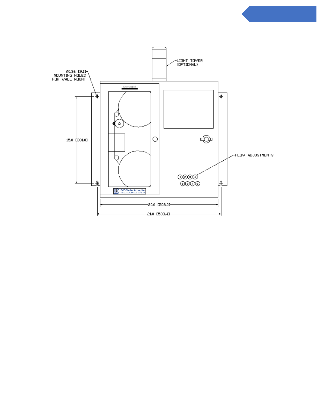
3.2 Mounting
Figure 3.1
Front
Page 18
18
DC-ITD-CL4andCL8MAN01.A www.dodtec.com
NOV 2018 815-788-5200
CL4 & CL8 Manual
Figure 3.2
Figure 3.4
Top
Right
Side
Page 19
19
DC-ITD-CL4andCL8MAN01.A www.dodtec.com
NOV 2018 815-788-5200
CL4 & CL8 Manual
Refer to figure 3.1 for dimensional requirements for wall mount. Be sure the CL4/CL8 is properly secured to
the wall.
3.3 Sample Tubing
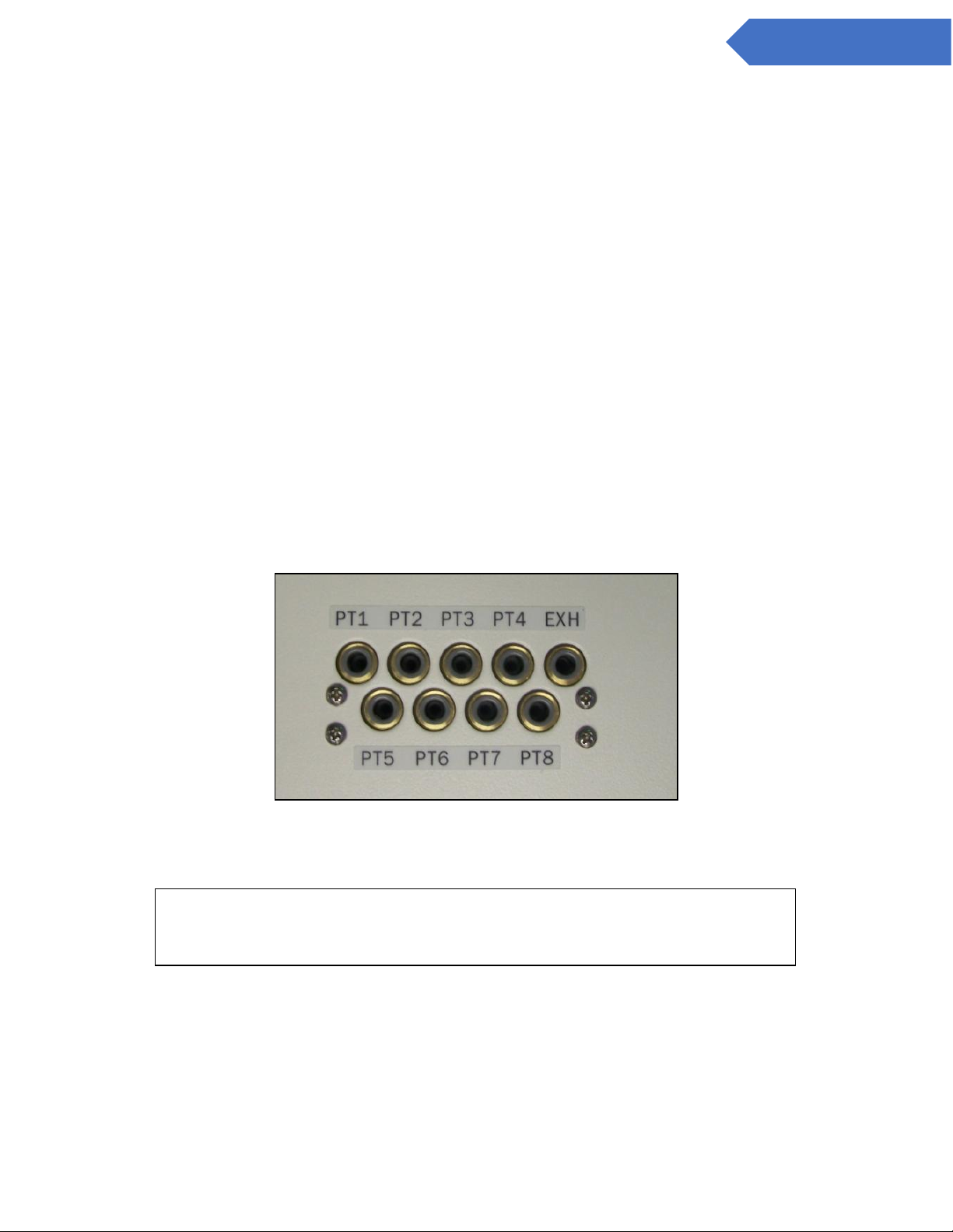
Sample tubing may be connected to the CL4/CL8 on the top or left side of the CL4/CL8 (see section 3.3.1). All
sample tubes are 1/4” OD x 3/16” ID Teflon FEP (300 ft max length) which may be purchased from DOD
Technologies, INC (See Appendix A).
Fully depress each sample tube into the proper hole when attaching. To detach the tube, push on the collet
and pull the tubing out
3.3.1 Sample Manifold Relocation
The quick connect system used to attach sample tubing and exhaust may be located on the top or left side of
the machine. To move the manifold, Follow the procedures in section 6.2 to open the service door.
• Remove the four (4) mounting screws shown in figure 3.5 to detach the manifold.
• Remove the 4 lock nuts holding the cover plate over the unused manifold opening
• Remove the cover plate
• Align the manifold inside the CL4/CL8 with the holes in the new position
• Replace the screws holding the manifold in place and tighten accordingly.
• Replace the cover plate over the unused opening and secure with the four lock nuts.
Figure 3.5
Sample tubing may be purchased from DOD technologies (see appendix A)
3.3.2 End of line particulate filters
End of line particulate filters must be installed on all 4/8 sample lines at all times to prevent damage to the
unit. Unused lines must either be plugged or have a filter installed. Filters require regular maintenance – see
chapter 6.
IMPORTANT: All sample tubing used with the CL4/CL8 must be 1/4”OD x 3/16”
ID FEP Teflon. Use of any other tubing may damage the CL4/CL8 and/or cause
inaccurate gas concentration readings.
Page 20
20
DC-ITD-CL4andCL8MAN01.A www.dodtec.com
NOV 2018 815-788-5200
CL4 & CL8 Manual
End of line particulate filters may be purchased from DOD technologies (see appendix A)
3.4 Exhaust tubing
The exhaust line must be 3/8” OD x 1/4” ID tubing with a maximum length of 25ft. Polyethylene is
recommended although polypropylene or Teflon may also be used.
Exhaust tubing may be purchased from DOD technologies (see appendix A)
3.5 A/C Power
A 6ft power cord is included – DO NOT use extension cords with the CL4/CL8. Longer cords are available
from most electrical supply stores.
3.6 Output Wiring
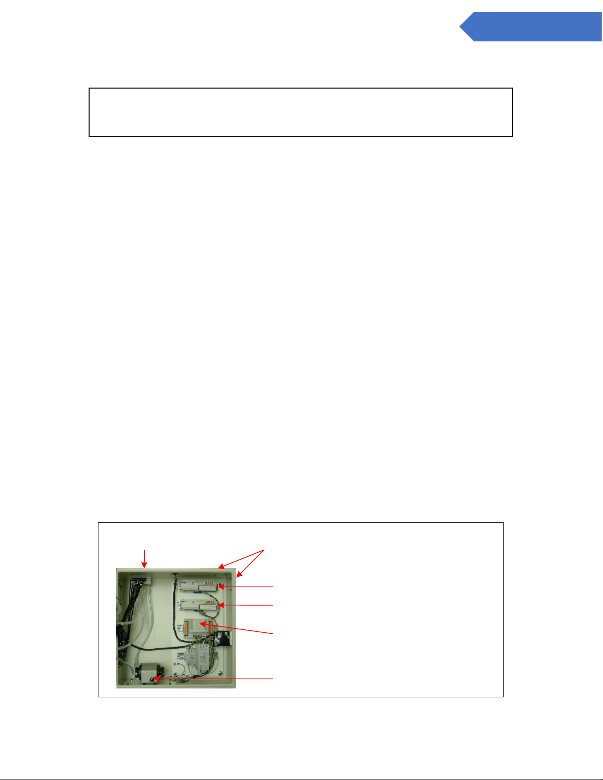
Figure 3.2 details the connection method for both the standard relay output module and the optional 4 to 20
ma modules.
See Appendix B for a listing of output module connections.
3.6.1 Standard Output Relay Module Wiring
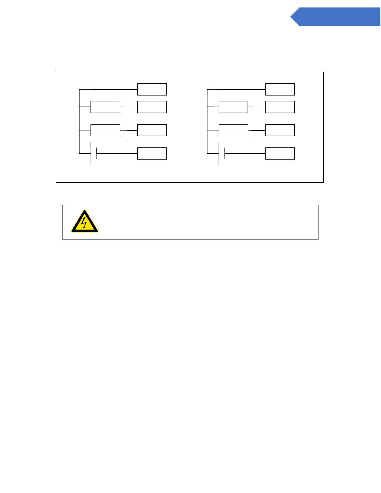
The standard output module requires an external 24V supply connected to V1+/- and V2+/- (see Appendix B).
Outputs 0-15 are powered through V1 while outputs 16-31 are powered through V2. Each output can handle
up to 0.2 Amps with a total maximum current of 1.6Amps to each group of 16 outputs at any time. See figure
3.6 and 3.7 for information on wiring the CL4/CL8 standard relay outputs.
IMPORTANT: All points require filtration to prevent dust accumulation in tubing and
internal damage to the CL4/CL8. Dust that collects in the tubing or the internal
system may cause sample loss and inaccurate gas concentration readings.
Wiring knockouts on sides of
cabinet
Service
Door
Open
DOD 4 to 20ma Module 1
DOD 4 to 20ma Module 2
DOD Output Relay
Module
Pump
Page 21
21
DC-ITD-CL4andCL8MAN01.A www.dodtec.com
NOV 2018 815-788-5200
CL4 & CL8 Manual
Figure 3.6
Figure 3.7
Use only AWG22 to AWG18 twisted wire (wire sizes UL1015 and UL1007)
Strip from .26” to .31” (6.5mm to 8.0mm) from each wire to insert into the connector.
1. To connect the wires to the spring-loaded output connector:
2. Insert the screwdriver into the square shaped hole which will open the round hole for the wire.
3. Continue to hold the screwdriver while inserting the wire into the round shaped hole.
4. While holding the wire in place remove the screwdriver which closes the clamp onto the wire.
5. IMPORTANT: Be sure the wire is inserted completely into the hole. Failure to do so could result in
system failure, electrical shock.
6. To remove a wire, re-insert the screwdriver in the hole as described in step 1 and gently pull the wire
out while the spring is compressed.
V1 +
V1 -
LOAD
+ 24V -
…
OUT 0
OUT 15
LOAD
V2 +
V2 -
LOAD
+ 24V -
…
OUT 16
OUT 31
LOAD
DANGER: Before performing any wiring modifications, be sure that
power to the CL4/CL8 is disconnected and remove the output
connector from the output relay block.
Page 22
22
DC-ITD-CL4andCL8MAN01.A www.dodtec.com
NOV 2018 815-788-5200
CL4 & CL8 Manual
3.6.2 Optional 4 to 20ma Output Module Wiring
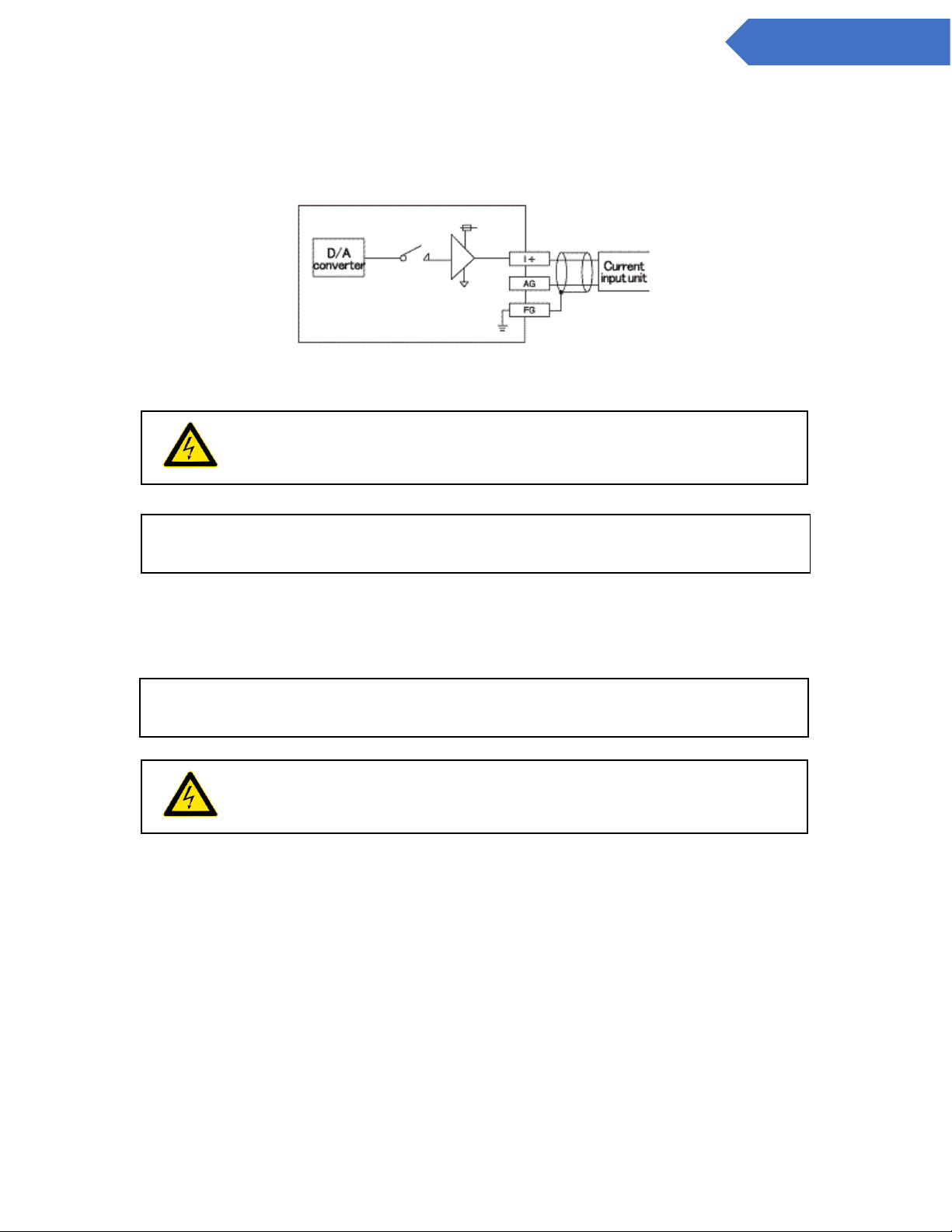
Figure 3.8 details a typical connection to one of the eight (8) 4 to20ma output connections. See Appendix B
for a complete list of terminal connections on the optional 4 to 20ma output block.
Figure 3.8
3.6.3 Optional 8 Point Relay Module (Item #2-500-012)
See Appendix B for a complete list of terminal connections on the optional output block.
IMPORTANT: Verify that all I/O unit terminal screws are securely tightened even if
they are not used.
DANGER: Before doing any wiring, modifications be sure that power
to the CL4/CL8 is disconnected.
IMPORTANT: Verify that all I/O unit terminal screws are securely tightened even if
they are not used.
DANGER: Before doing any wiring, modifications be sure that power
to the CL4/CL8 is disconnected.
Page 23

23
DC-ITD-CL4andCL8MAN01.A www.dodtec.com
NOV 2018 815-788-5200
CL4 & CL8 Manual
Chapter 4 - Setup & Configuration
4.1 Set system date and time
See section 5.2.2
4.2 Gas Selection
Each point on the CL4/CL8 must be setup for the appropriate gas and configured accordingly. See section
5.2.1 for information on selecting the gas for each point.
4.3 Alarm Settings
See section 5.2.a for information on how to adjust the alarm settings after the gas has been selected for each
point.
4.4 Output Relays
The CL4/CL8 supports both energized and de-energized relays and may be configured for either latching or
non-latching faults/events.
When configured for energized relays, the outputs are normally in a high state and change to a low state
when the corresponding fault / alarm occurs. De-energized relays work in the opposite manner. See section
5.2.f. When the power is ON, the Power Loss relay is always in the normally high state.
When latched outputs are selected (section 5.2.f), any fault or alarm that occurs will remain until the ‘fault
reset’ button is touched. If non-latching outputs are selected the output will reset automatically if, and when,
the condition that caused the fault/alarm goes away.
NOTE: A message is added to the event log each time the ‘fault reset’ button is touched.
4.5 Concentration Logging
Three levels of concentration logging can be configured in the CL4/CL8.
1. >0 - All concentrations detected >= LDL are added to the concentration log.
2. AP1 - Anytime alarm level 1 is reached, the concentrations are added to the log.
3. AP2 - Anytime alarm level 2 is reached, the concentrations are added to the log.
Regardless of which point the gas is detected on, all CL4/CL8 points are logged as long as the trigger is
active. For AP1 or AP2 logging the system will continue to log concentrations as long as the alarm level is
active. If latching faults are enabled the system will continue to log until the ‘fault reset’ button is touched.
See section 5.3
4.6 Install new tape
Page 24

24
DC-ITD-CL4andCL8MAN01.A www.dodtec.com
NOV 2018 815-788-5200
CL4 & CL8 Manual
See section 6.3 for installation instructions.
4.7 USB Memory Stick
The use of a USB Memory Stick is highly recommended to retain historical and performance information
including events, alarms, and gas concentrations. USB Memory Sticks are available from DOD technologies
(see Appendix A) and at most retail electronic stores. See section 6.4 for information on inserting and
replacing a USB Memory Stick. See also Appendix F for information on the data stored on the USB Memory
Stick.
4.8 Setup Complete
Enter analysis.
Page 25
25
DC-ITD-CL4andCL8MAN01.A www.dodtec.com
NOV 2018 815-788-5200
CL4 & CL8 Manual
Chapter 5 – Basic Operation
CL4/CL8 Menu Overview
I. Initialization (Power on) (sec. 5.1)
a. Setup Mode
b. Timer
II. Setup (11 button menu) (sec. 5.2)
a. Gas & Alarm Settings
i. Points 1-4
ii. Points 5-8
b. Set Date/Time
c. Load Tape
d. Adjust Flow
e. *Calibration Factors
f. *Set/Test Outputs
g. **Factory Settings
h. Events History
i. Fault Reset
j. Start Analysis
III. Concentration Log (sec. 5.3)
IV. Analysis (5 buttons & 8 points w/detail) (sec. 5.4)
a. Setup
b. Concentration Log
c. Event History
d. Silence
e. Fault Reset
f. Point Detail (1-8)
V. USB Memory Log (sec. 5.5)
VI. Time weight average (sec. 5.6)
Legend
User Screens
(No Password Required)
*Administrative Screens
(Administrator Password Required)
**Service Screens
(Service Password Required)
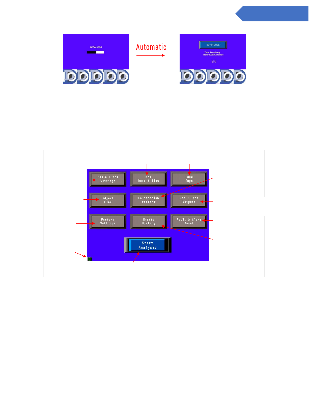
5.1 Initialization
When the CL4/CL8 is powered on it will begin with an initialization screen (figure 5.2) which is followed by the
restart screen (figure 5.3).
Page 26
26
DC-ITD-CL4andCL8MAN01.A www.dodtec.com
NOV 2018 815-788-5200
CL4 & CL8 Manual
Figure 5.2 Figure 5.3
If the operator touches the ‘SETUP MODE’ button before the timer reaches 0 the Setup screen appears
(section 5.2) otherwise after a timeout the system will start analysis (section 5.4)
5.2 Setup / Main Menu
The setup menu is accessed either by touching the ‘SETUP MODE’ button on power up (section 5.1) or by
touching ‘SETUP’ from the analysis screen (section 5.5). Figure 5.4 below shows the setup screen and
explains the various buttons.
Figure 5.4
View/Reset tape usage counter.
(Section 5.2.c)
Set system Date & Time (section
5.2.b)
Touch to reset all
active faults &
alarms.
Touch to Start Analysis (Section 5.5)
Touch to
display
version and
configuration
information.
Service password
required
Flow adjustment
– (section 5.2.d)
Gas selection
and alarm level
settings
(Section 5.2.a)
Adjust Calibration
Factors
(Section 5.2.e)
Set latching outputs and
test outputs.
(Section 5.2.f)
View alarms, system
events, conc. Log,
and other files on
USB Memory Stick.
(Section 5.2.h)
Page 27
27
DC-ITD-CL4andCL8MAN01.A www.dodtec.com
NOV 2018 815-788-5200
CL4 & CL8 Manual
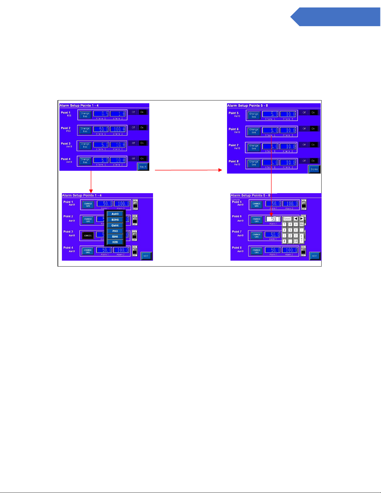
5.2.1 Gas & Alarm Settings Menu
Touching the ‘GAS & ALARM SETTINGS’ button on the setup screen brings up the screen shown on the left in
figure 5.5 which displays the configuration of points 1-5. Touching the ‘NEXT’ button will bring up the screen
shown on the right of figure 5.5 which displays the configuration of points 5-8. Touching the ‘BACK’ button
will then return to the SETUP screen.
Figure 5.5
Touching the ‘CHANGE GAS’ button brings up the gas selection menu from which you may either select a new
gas or touch the ‘Cancel’ button. Touching any of the alarm level numeric displays will bring up the keypad to
change the alarm level. The valid alarm levels are listed in Appendix X for each gas. An invalid alarm level
entry will bring up an error message.
The toggle switch to the right of each point allows the individual points to be disabled when not in use. The
word ‘DISABLED’ will then appear on the analysis screen for that point and no calculations will be made.
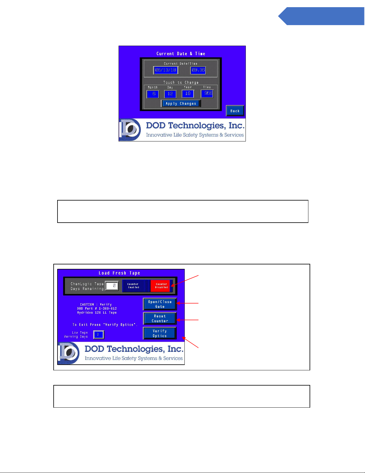
5.2.2 Set Date/Time
Touching the ‘SET DATE/TIME’ button on the setup screen brings up the screen shown in figure 5.6.
Next for points 5-8.
Touch ‘CHANGE GAS’ to
bring up selection menu.
Touch the Alarm
Level # to change.
Page 28
28
DC-ITD-CL4andCL8MAN01.A www.dodtec.com
NOV 2018 815-788-5200
CL4 & CL8 Manual
Figure 5.6
Touching any of the numeric displays for Month, Day, Year, and Time will bring up the numeric entry keypad.
The time must be entered in 24-hour (Military) time format. Touch the ‘BACK’ button to return to the setup
menu.
5.2.3 Load Tape
Touching the ‘LOAD TAPE’ button on the setup screen brings up the screen shown in figure 5.7.
Figure 5.7
IMPORTANT: After entering the new date & time you must touch the ”Apply
Changes” button to update the system date/time.
Touch to reset tape counter
after installation
Enable/Disable Tape Days
remaining counter & fault.
Open & Close gate as
needed to install tape.
To exit screen you must
press this button to verify
IMPORTANT: Each time a new tape is loaded into the CL4/CL8 the ‘RESET
COUNTER’ button must be touched to accurately track tape usage.
Page 29
29
DC-ITD-CL4andCL8MAN01.A www.dodtec.com
NOV 2018 815-788-5200
CL4 & CL8 Manual
Each time the ‘OPEN/CLOSE GATE’ button is touched, the gate will open or close appropriately. If the gate is
currently closed, touching the button will open the gate. If the gate is currently open* touching the button will
close the gate.
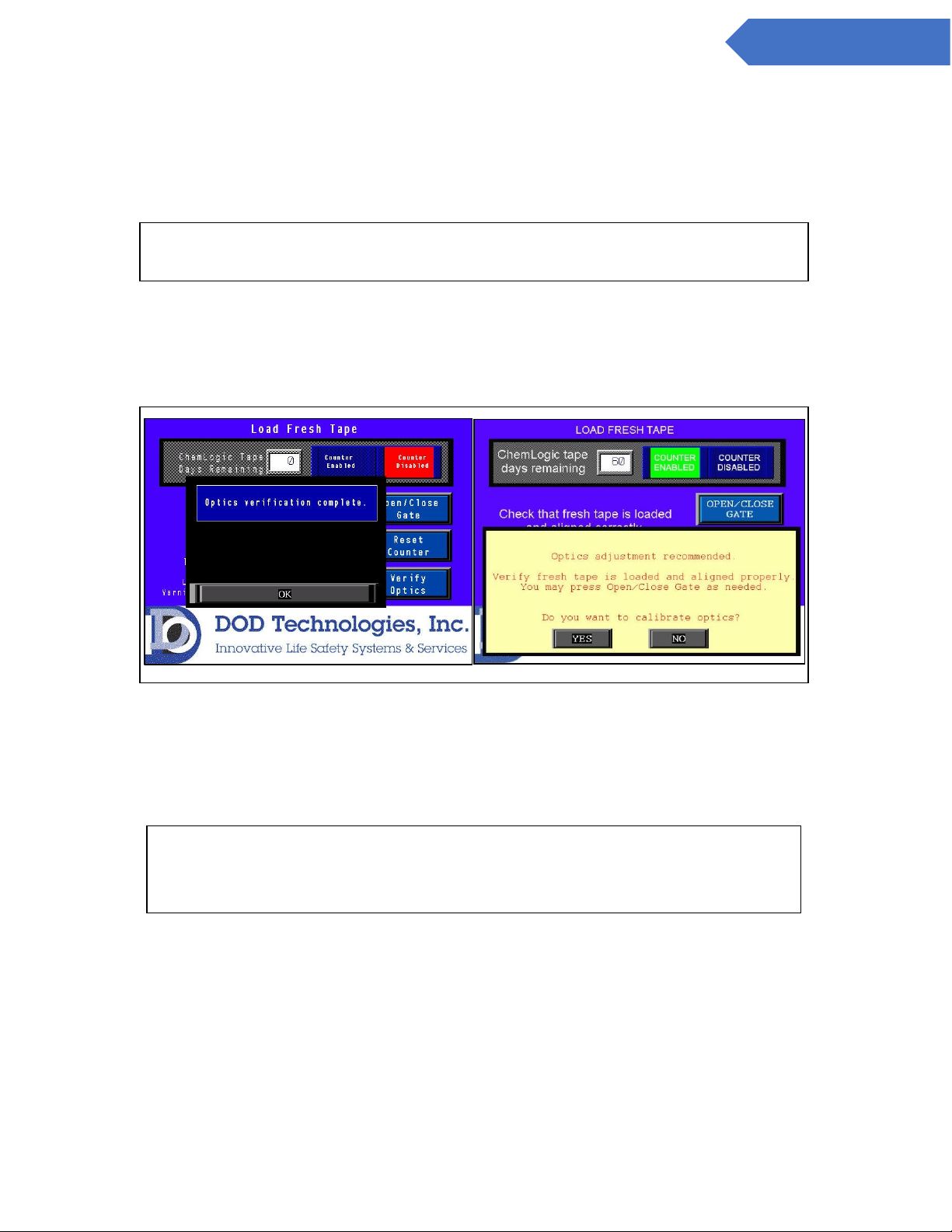
To Exit the screen optics verification is required. When the ‘Verify Optics’, button is touched the machine will
verify the tape is aligned correctly and the optics are calibrated appropriately. During this time a ‘ONE
MOMENT PLEASE’ window will appear. When verification is complete one of the two screens in figure 5.8 will
appear.
Figure 5.8
If successful touch the “OK” button to return to the setup menu. If unsuccessful verify that the tape is
installed and aligned correctly by using the ‘OPEN/CLOSE GATE’ button as needed. Once you have verified
that the tape is installed correctly you can touch the ‘YES’ button to recalibrate the optics for the new tape or
press ‘NO’ to return to the setup menu.
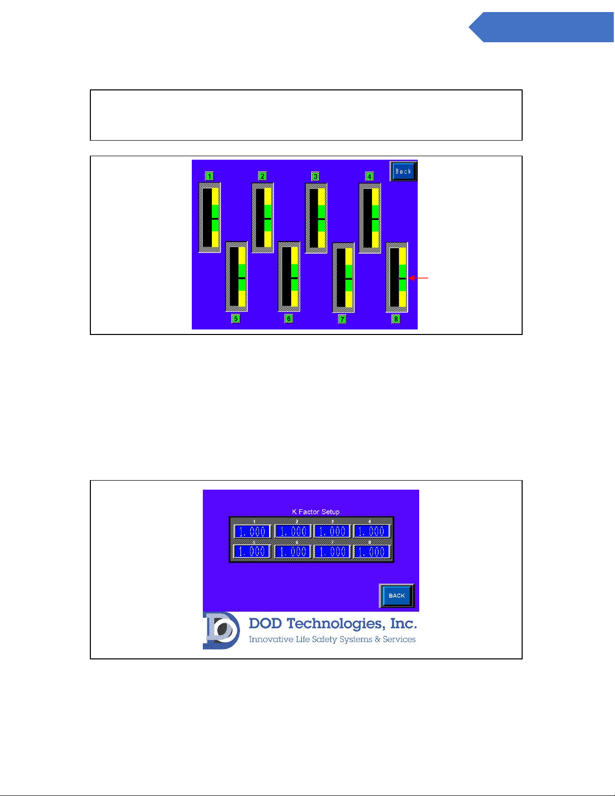
5.2.4 Flow Adjustment
Touching the ‘ADJUST FLOW’ button on the setup screen brings up the screen shown in figure 5.9 along with
advancing the tape and turning the pump on. Use the corresponding flow adjustment knobs located on the
front panel to adjust the flow so that each level is as close as possible to the black line in the middle of the
green section.
NOTE: If the gate is not completely open touching the button will open the gate to
the proper open position. Touch the button again to close.
IMPORTANT : If you choose ‘NO’ when asked to calibrate the optics as shown to
the right of figure 5.8 the CL4/CL8 may not function properly. Contact DOD
Technologies for more information.
Page 30
30
DC-ITD-CL4andCL8MAN01.A www.dodtec.com
NOV 2018 815-788-5200
CL4 & CL8 Manual
Figure 5.9
Touch the ‘BACK’ button to return to the setup menu.
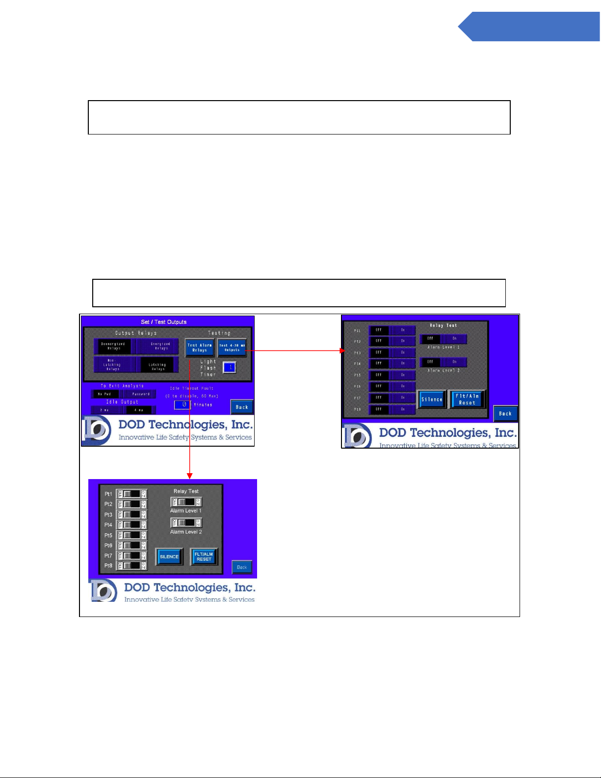
5.2.5 Calibration Factors
Touching the ‘CALIBRATION FACTORS’ button on the setup screen brings up the screen shown in figure 5.10
This screen requires administrator password access. Contact DOD (see chapter 7) for information on the use
of Calibration Factors.
Figure 5.10
*NOTE: There may be a slight delay between the time the knob is turned, and the
updated reading is reflected on the screen. Adjust the knob slowly and wait a few
seconds to verify that the level is accurate.
Adjust flow to
this level.
Page 31
31
DC-ITD-CL4andCL8MAN01.A www.dodtec.com
NOV 2018 815-788-5200
CL4 & CL8 Manual
Touching any of the numeric displays for any of the channels will bring up the numeric entry keypad. The
value entered must be between 0.5 and 2.000 for each channel.
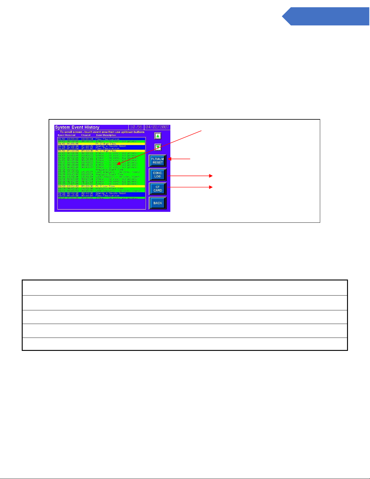
5.2.6 Set & Test Outputs
Touching the ‘SET/TEST OUTPUTS’ button on the setup screen brings up the screen shown in figure 5.11.
This allows the user to test relays and analog outputs.
Two other features on this screen:
1. Require a password to exit analysis – If enabled the level 1 password must be used for anyone to exit
the analysis screen. When disabled a simple “Are you sure?” window appears.
2. Idle Timeout – Set from 1-60 minutes to trigger a fault when the machine is left in idle. Setting this to
0 minutes disables the fault.
Figure 5.11
NOTE: This screen requires the Administrator password for access – See section
2.4
CAUTION: Activating these outputs will trigger any connected alarms
Output Relay Test
Alarm Relay Test
Page 32
32
DC-ITD-CL4andCL8MAN01.A www.dodtec.com
NOV 2018 815-788-5200
CL4 & CL8 Manual
5.2.7 Factory Settings
This button is reserved for technical service and requires a service password. Contact DOD Technologies,
INC (section 7) for service information.
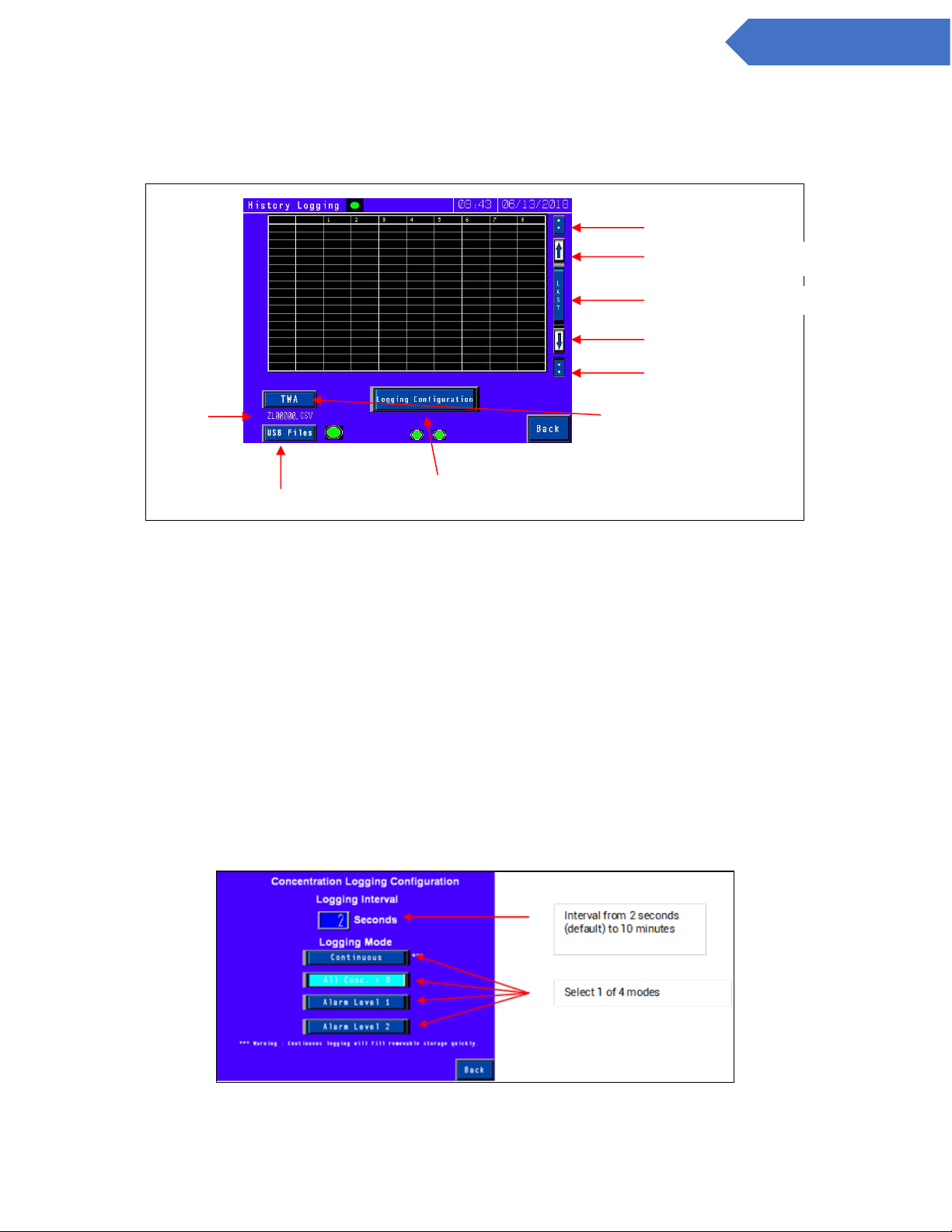
5.2.8 Event History
Touching the ‘EVENT HISTORY’ button on the setup screen brings up the screen shown in figure 5.11.
Figure 5.12
The event history is display with the most recent event/alarm at the top using the color coding listed in table
5.1.
Table 5.1
Green
Normal operation messages
Yellow
Fault messages
Blue
Informational display messages – non-critical
Orange
Critical Service messages
Red
Gas alarm messages
Touch the ‘BACK’ button to return to the setup menu.
Touch inside this message area and
then use the green up and down arrows
to scroll the screen. Most recent
messages appear on top.
Reset active faults & alarms.
See section 5.3
See section 5.5
Page 33
33
DC-ITD-CL4andCL8MAN01.A www.dodtec.com
NOV 2018 815-788-5200
CL4 & CL8 Manual
5.3 Concentration Log
Touching the ‘CONC LOG’ button on the Event History screen (section 5.2.9) will bring up the screen shown in
figure 5.13.
Figure 5.13
The log displays the concentration on each point when the trigger criteria is met. If you select >0 the system
will log all CL4/CL8 points when any of the points have a concentration reading which is >LDL for the gas
selected. (See appendix E).
The buttons on the right of the screen allow scrolling through the most recently logged readings. Touch the
configuration button to set the logging parameters.
5.3.1 Concentration Configuration
Figures 5.12.b shows the concentration configuration screen. Four levels of logging area available
depending on your needs.
1. Alarm Level 2 – Logging on when any channel is above alarm level 2
2. Alarm Level 1 – Logging on when any channel is above alarm level 1.
3. 0 – Logging on when any channel is above 0
4. Continuous – Logging always on (not recommended)
Figure 5.12b
Page Up
Up 1 message
Go to last message
Down 1 message
Page Down
See section 5.5
Current
log file
name
Go to Concentration configuration Page (See section
5.3.1)
See section 5.6
Page 34
34
DC-ITD-CL4andCL8MAN01.A www.dodtec.com
NOV 2018 815-788-5200
CL4 & CL8 Manual
In addition, the logging interval can be adjusted from the default of 2 seconds to a maximum of 10 minutes
(600 seconds).
5.4 Analysis Mode
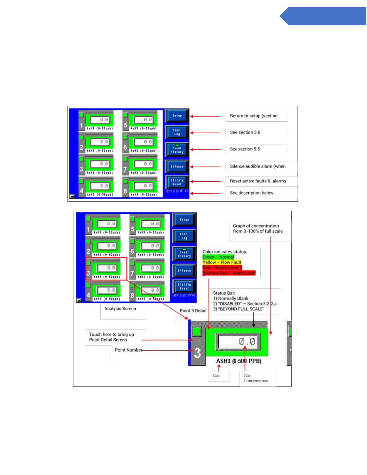
Figures 5.13 shows the main analysis screen which is entered either automatically during power on or by
touching the ‘START ANALYSIS’ button on the setup screen. Figure 5.14 shows the main analysis screen
with a detailed view of the information on point 3.
Figure 5.13
Figure 5.14
Page 35
35
DC-ITD-CL4andCL8MAN01.A www.dodtec.com
NOV 2018 815-788-5200
CL4 & CL8 Manual
At the bottom of the analysis screen on the right side is the current date & time and a message box below it.
The message box will either display the blinking message ‘NO USB Memory Stick or will be blank if a USB
Memory Stick is inserted in the machine. (See section 2.5.)
To display detailed information on any point touch along the left-hand side from the point # to the square box
above it which will bring up the point detail screen (section 5.5.1).
Touch the ‘BACK’ button to return to the setup menu.
5.5.1 Point Detail screen
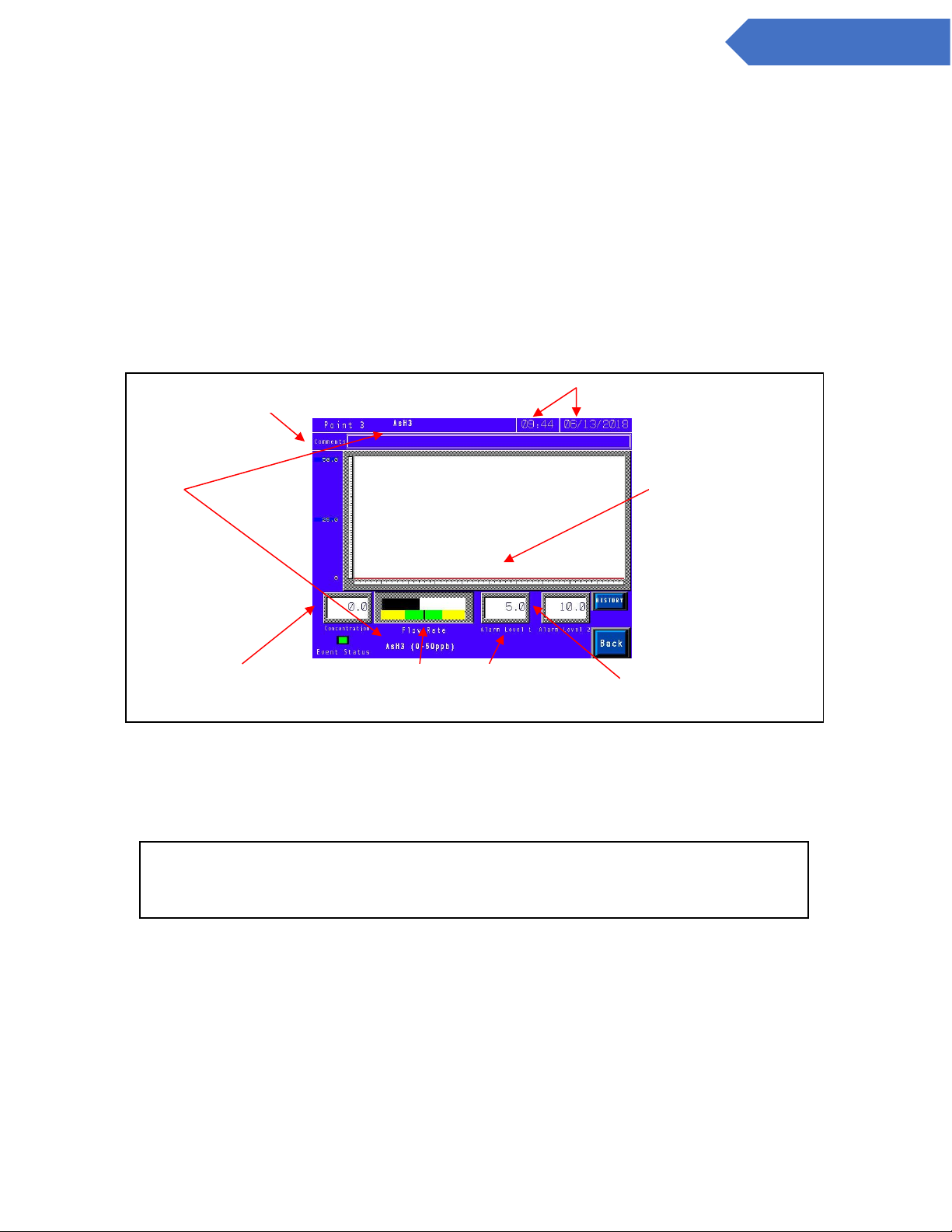
Touching a point # on the analysis screen (Section 5.4) will bring up the point detail screen shown in figure
5.15
Figure 5.15
The information on the point detail screen is updated in real time while in analysis mode. Alarm levels may
be changed by touching the numeric display area for the appropriate alarm. Similarly, the comments related
to this point may be edited by touching anywhere in the box displayed for comments.
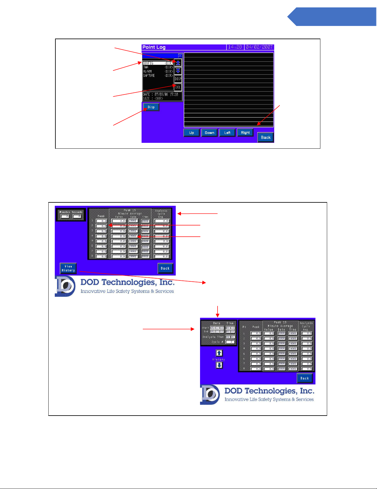
5.5 USB Memory Stick log
Figures 5.16 shows the ‘CF Log’ which is displayed by touching the ‘CF Files’ button on the concentration log
(Section 5.3). This screen allows the user to browse everything contained on the USB Memory Stick currently
inserted. (Note – if no USB Memory Stick is present or there is an error reading the card, the left selection
screen will appear blank). To initiate the display touch ‘DISP’.
Gas
and
full scale
range
User entered comments
Trend graph of gas
concentration on this
Current alarm limits for
this point.
Current
concentration
Current Flow
Setting
Point disabled
message
NOTE: The display of the current flow may not be immediately displayed on this
screen. It is recommended that the flow adjustment screen
(section 5.2.4) be used for all flow calibration.
Page 36
36
DC-ITD-CL4andCL8MAN01.A www.dodtec.com
NOV 2018 815-788-5200
CL4 & CL8 Manual
Figure 5.16
5.6 Time Weighted Average (TWA)
Touching the ‘TWA’ button on the concentration log screen (section 5.3) brings up the TWA screen shown in
figure 5.17.
Figure 5.17
List of items in
current folder
w/current selection
highlighted.
Touch ‘DISP’ to
display contents of
selected folder or
Delete selected
Arrow keys to
scroll through list
Use these
keys to
navigate
when
viewing a
file.
TWA information for current analysis cycle.
Use the arrow keys to
scroll through the
previous 5 analysis
cycles.
Details of selected analysis cycle. Start & End
Date/Time, actual analysis time, and cycle
number (sequencial #).
Peak value reached in current cycle
Highest 15 minute average reached including
date/time of occurrence.
Page 37

37
DC-ITD-CL4andCL8MAN01.A www.dodtec.com
NOV 2018 815-788-5200
CL4 & CL8 Manual
The first screen displays the current TWA information including the minutes and seconds elapsed since the
cycle started. The CL4/CL8 retains the most recent 5 analysis cycles (up to 40 hours) in addition to the
current cycle in memory. The previous cycles are accessed by touching the ‘View History’ button which
brings up the screen shown in the lower right of figure 5.17. Use the up and down arrows to review the
previous 5 cycles in this screen.
Page 38
38
DC-ITD-CL4andCL8MAN01.A www.dodtec.com
NOV 2018 815-788-5200
CL4 & CL8 Manual
Chapter 6 – Maintenance
It is recommended for complete safety that the ChemLogic 4/8 continuous gas detection system be serviced
on-site every 6 months by a certified DOD Service Engineer or by submitting the unit to the manufacturer for
routine maintenance. A certificate of repair should be received and kept with operation documents of the
machine. Any malfunctions in the device should be reported and corrected before further use.
6.1 Maintenance Door Access
The maintenance door is used to access the ChemLogic tape. To open the maintenance door simply turn the
maintenance door locking knob counterclockwise until it is unscrewed from the main panel. The door can
then be opened.
When maintenance is complete be sure to close the maintenance door and hand tighten the maintenance
door locking knob (clockwise) to secure the door.
6.2 Service Door Access
To open the door:
1. Insert the key provided into the slot and rotate counter clockwise to unlock the unit.
2. Turn the latch counterclockwise to unlatch the door.
3. Open the door for service as required.
When service is complete be sure to close the service door and secure the keyed latch to the closed position.
Verify that the service door cannot be pulled open – secure the door using the key to lock the door.
6.3 ChemLogic Paper tape
The ChemLogic paper tape has an expiration date printed on the label. Expired tape should be disposed of
and replaced with new tape to assure proper gas concentration readings. Each DOD ChemLogic tape
cartridges will last for 60 days under normal usage. See Appendix A for ordering information.
IMPORTANT: The maintenance door should remain securely latched at all times
except when servicing the ChemLogic tape.
DANGER: Turn off the unit and unplug A/C power to the unit before
opening the Service Door.
IMPORTANT: The service door must remain securely latched at all times when not
servicing the unit. Verify that the latch is secure and use the keyed lock to prevent
unauthorized access.
Page 39
39
DC-ITD-CL4andCL8MAN01.A www.dodtec.com
NOV 2018 815-788-5200
CL4 & CL8 Manual
ChemLogic Paper Tape Installation Procedure
A. From the setup menu touch the ‘Load Tape’ button (section 5.2.3)
B. Open the maintenance door. (Section 6.1)
C. On the screen touch the ‘OPEN/CLOSE GATE’ button to open the gate
D. Remove the old take-up reel by gently pulling and dispose of properly
E. Remove the empty tape reel and install on top as the new take-up reel.
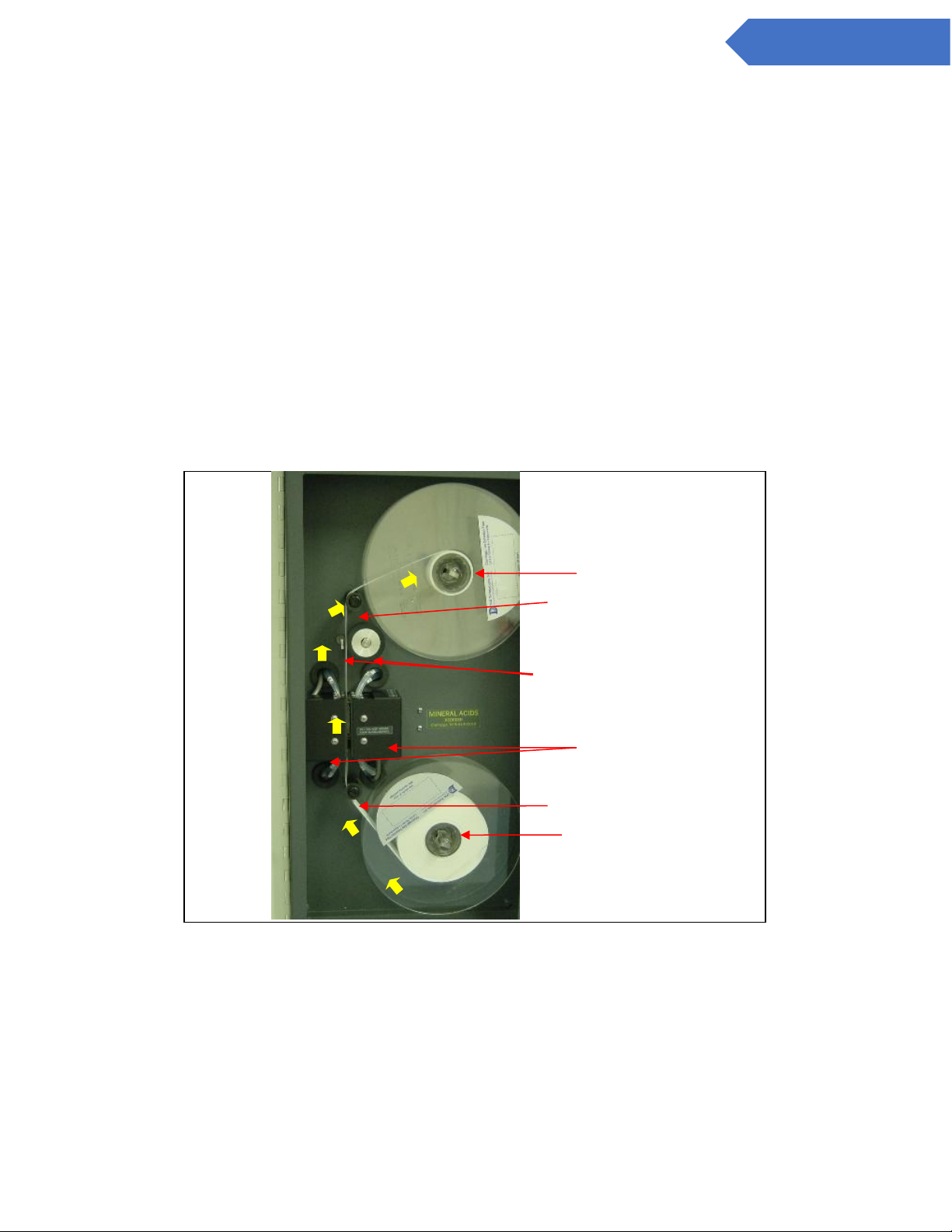
F. Secure the new ChemLogic tape reel on the bottom as shown in figure 6.1. The tape should be around
the bottom in a clockwise direction as shown.
G. Feed the tape as shown with the arrows in figure 6.1.
1. From the bottom reel
2. Around the bottom tape guide
3. Through the opening between the optic blocks
4. Between the rubber roller and the capstan
5. Around the top of the upper tape guide
6. Fold the end of the tape and insert into the slot in the empty tape reel. Be sure the tape is wound
clockwise around the take-up reel.
Figure 6.1
H. Turn the upper wheel clockwise at least 2 full turns to secure the tape
I. On the screen touch the ‘OPEN/CLOSE GATE’ button to close the gate
J. On the screen touch the ‘Reset Counter’ button. (See section 5.2.3)
Warning: Keep fingers clear during tape advance.
Upper tape reel
1 2 3
4
5
6
Lower tape reel
Optic Blocks
Bottom tape guide
Top tape guide
Capstan / Rubber roller
Page 40
40
DC-ITD-CL4andCL8MAN01.A www.dodtec.com
NOV 2018 815-788-5200
CL4 & CL8 Manual
6.4 End of line particulate filters
End of line (point of detection) particulate filters which protect the CL4/CL8 from damage are required on all
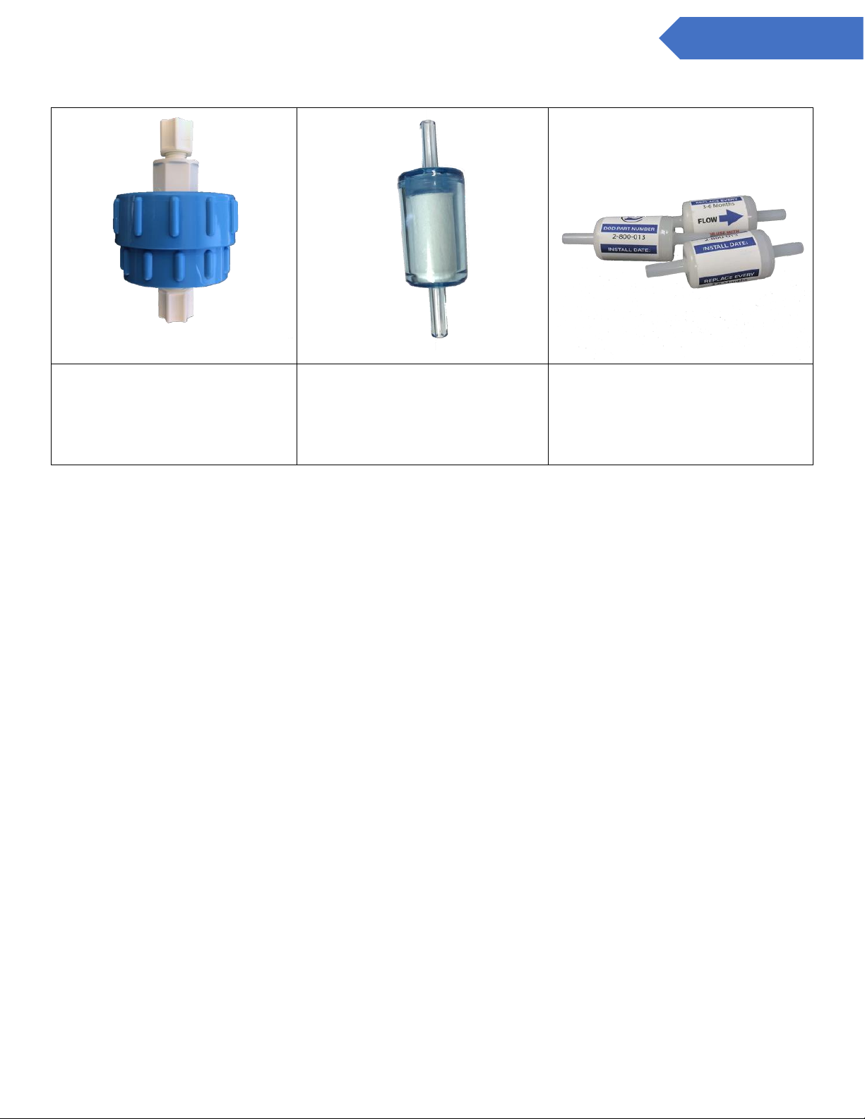
4/8 points including points not being monitored. Table 6.1 details the type of filter required for each gas –
see also figure 6.2. Filters must be replaced on a regular basis as shown in the table. Filter orientation is not
critical in either application.
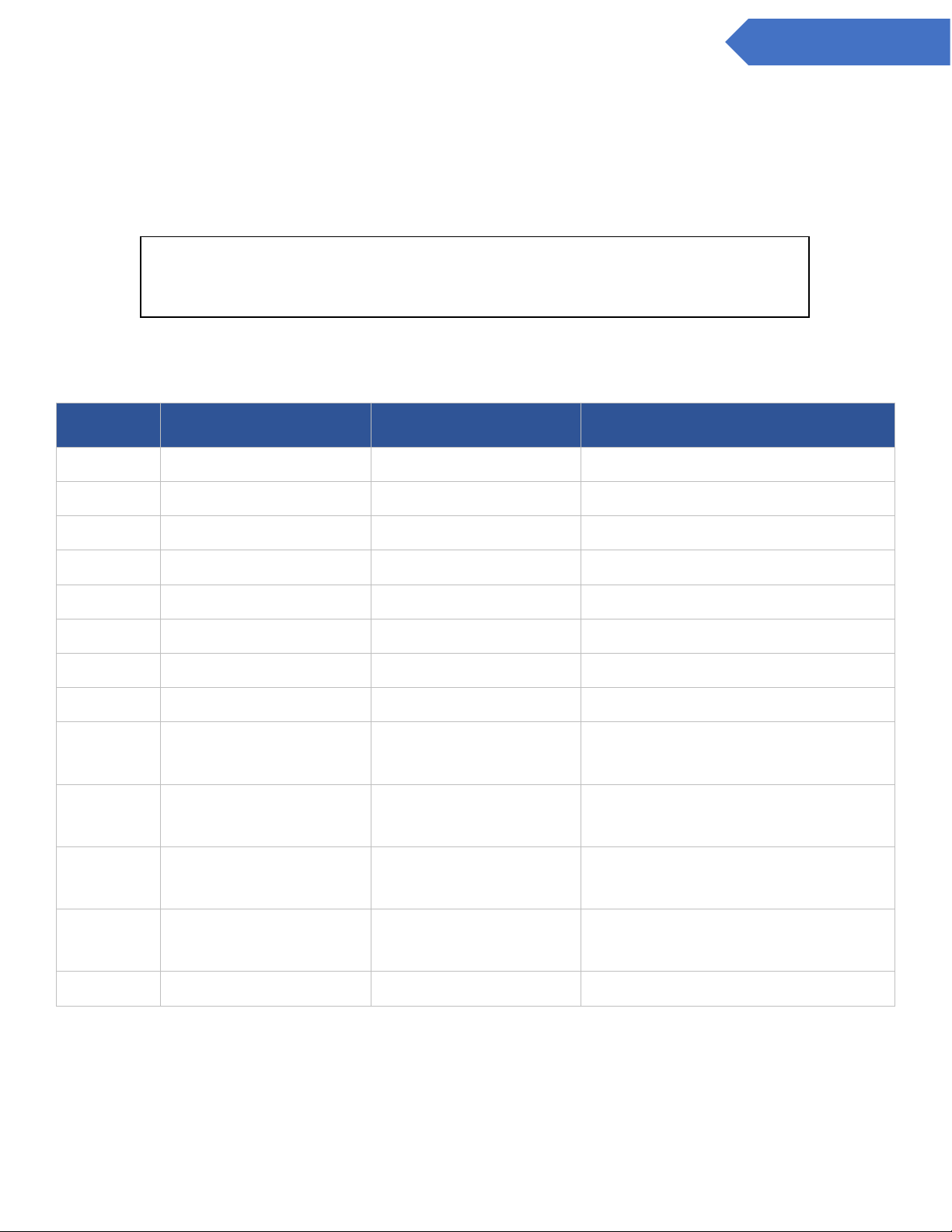
Table 6.1
Gas
Description
Suggested Replacement
DOD Filter Part #
AsH3
Arsine
6 Months
780248
B2H6
Diborane
6 Months
780248
GeH4
Germane
6 Months
780248
H2SE
Hydrogen Selenide
6 Months
780248
PH3
Phosphine
6 Months
780248
SiH4
Silane
6 Months
780248
TBA
Tertiary-Butyl-Arsine
6 Months
780248
H2S
Hydrogen Sulfide
6 Months
780248
HCL
Hydrogen Chloride
1 Month (membrane)
60009 (Housing) 60010 (membrane)
OR
2-800-013
HF
Hydrogen Fluoride
1 Month (membrane)
60009 (Housing) 60010 (membrane)
OR
2-800-013
BF3
Boron Trifluoride
1 Month (membrane)
60009 (Housing) 60010 (membrane)
OR
2-800-013
HBR
Hydrogen Bromide
1 Month (membrane)
60009 (Housing) 60010 (membrane)
OR
2-800-013
COCL2
Phosgene
6 Months
780248
IMPORTANT: All points require filtration to prevent dust accumulation in tubing and
internal damage to the CL4/CL8. Dust that collects in the tubing or the internal
system may cause sample loss and inaccurate gas concentration readings.
Page 41
41
DC-ITD-CL4andCL8MAN01.A www.dodtec.com
NOV 2018 815-788-5200
CL4 & CL8 Manual
Mineral Acids Filter
Part Numbers:
Blue Housing: 60009
Filter Membrane: 60010
Hydrides & Phosgene Filter
Part Number:
780248
Mineral Acids Disposable Filter
Part Number
2-800-013
Figure 6.2
6.5 Flow adjustment
Each channel should be adjusted whenever a new ChemLogic tape or particulate filter is installed. See
section 5.2.4
6.6 USB Memory Stick replacement
It is highly recommended to keep a USB Memory Stick inserted in the unit at all times. The lower right corner
of the analysis screen will show when a card is properly inserted (see section 5.4) To insert or replace a USB
Memory Stick follow these steps below.
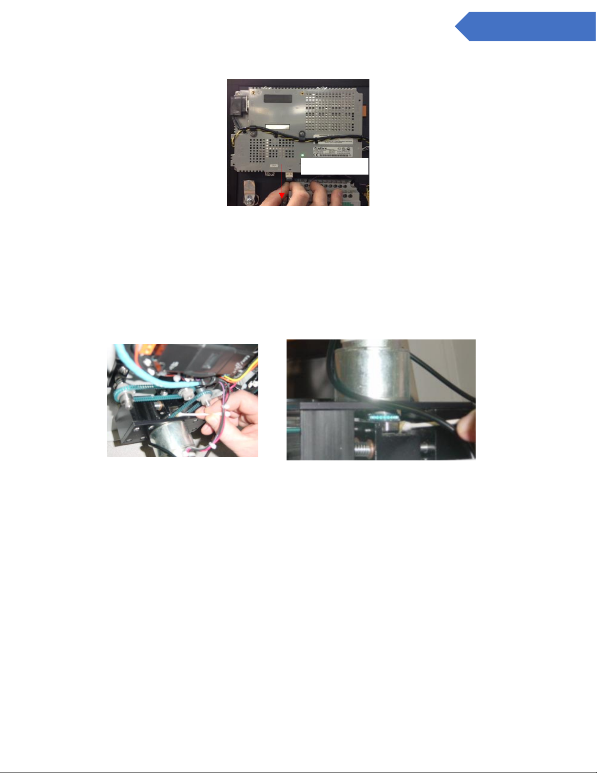
1) Locate USB slot on middle center of the HMI. It is marked USB.
2) Removal:
a) Pull USB Memory Stick straight down
3) Insertion:
Page 42
42
DC-ITD-CL4andCL8MAN01.A www.dodtec.com
NOV 2018 815-788-5200
CL4 & CL8 Manual
a) Push the USB Memory Stick straight up ensuring the USB Memory Stick and slot are aligned properly.
Figure 6.3
Section 5.5 describes viewing the files stored on the USB Memory Stick on the touch screen. Appendix F
details the data stored on the USB Memory Stick and how to access it on a personal computer.
6.7 Apply grease periodically
The cam attached to the gate motor should be greased every 6 months to prevent wear. Apply a small
amount of number 2 type petroleum or synthetic grease (such as McMaster Carr #1378K27) to the rounded
portion of the cam. – See Figure 6.4
Top of gate mechanism
Bottom of gate mechanism
Figure 6.4 -Grease may be applied either from the top of the gate mechanism or the bottom.
6.8 Fuse Replacement
The system power is fused with a 2 amp fast-acting (5x20mm) fuse.
DO NOT REMOVE
Page 43

43
DC-ITD-CL4andCL8MAN01.A www.dodtec.com
NOV 2018 815-788-5200
CL4 & CL8 Manual
Chapter 7 – Service & Support
For information on service and support for your CL4/CL8 contact DOD Technologies, INC. using the
information below.
For Permanent discontinuation:
Please contact DOD Technologies for the safe return of your equipment. All discontinued units will
be accepted back by DOD Technologies so proper recycling may take place. For information on how
to return the unit contact us using the below information:
Phone Support
M-F 8:30am – 5pm (Central Time Zone)
815.788.5200
Service Center
675 Industrial Drive Bldg. A.
Cary, IL 60013
Visit our website
www.dodtec.com
Page 44
44
DC-ITD-CL4andCL8MAN01.A www.dodtec.com
NOV 2018 815-788-5200
CL4 & CL8 Manual
Appendix A – Accessories / Cassettes
Page 45
45
DC-ITD-CL4andCL8MAN01.A www.dodtec.com
NOV 2018 815-788-5200
CL4 & CL8 Manual
Page 46
46
DC-ITD-CL4andCL8MAN01.A www.dodtec.com
NOV 2018 815-788-5200
CL4 & CL8 Manual
Appendix B – I/O Connection Detail
B.1 Standard Output Relay Module
Description
Output
Point 1 Alarm Level 1
0
Point 1 Alarm Level 2
1
Point 2 Alarm Level 1
2
Point 2 Alarm Level 2
3
Point 3 Alarm Level 1
4
Point 3 Alarm Level 2
5
Point 4 Alarm Level 1
6
Point 4 Alarm Level 2
7
Point 5 Alarm Level 1
8
Point 5 Alarm Level 2
9
Point 6 Alarm Level 1
10
Point 6 Alarm Level 2
11
Point 7 Alarm Level 1
12
Point 7 Alarm Level 2
13
Point 8 Alarm Level 1
14
Point 8 Alarm Level 2
15
Critical Fault
16
Watchdog
17
Power On
18
Analysis Mode
19
General Fault
20
Gas Alarm Level 1
21
Gas Alarm Level 2
22
Critical Fault (*)
23
General Fault (*)
24
Gas Alarm Level 1 (*)
25
Gas Alarm Level 2 (*)
26
Blue Light
27
Audible Alarm
28
Green Light
29
Orange Light
30
Red Light
31
(* ) Can be Energized / De-Energized
Output Relay Connector
0
1
Output
2 3 4 5 6
7
8
9
10
11
12
13
14
15
V1 +
V1 -
16
17
18
19
20
21
22
23
24
25
26
27
28
29
30
31
V2 +
V2 -
Connect 24 Volt supply to V1 +/- and V2
+/-. (See Connector diagram.)
Outputs 0-15 use common ground (V1 -)
Outputs 16-31 use common ground (V2
-)
0.2 Amp per output max current
Outputs 0-15 Max current 1.6A
Outputs 16-31 Max current 1.6A
Page 47
47
DC-ITD-CL4andCL8MAN01.A www.dodtec.com
NOV 2018 815-788-5200
CL4 & CL8 Manual
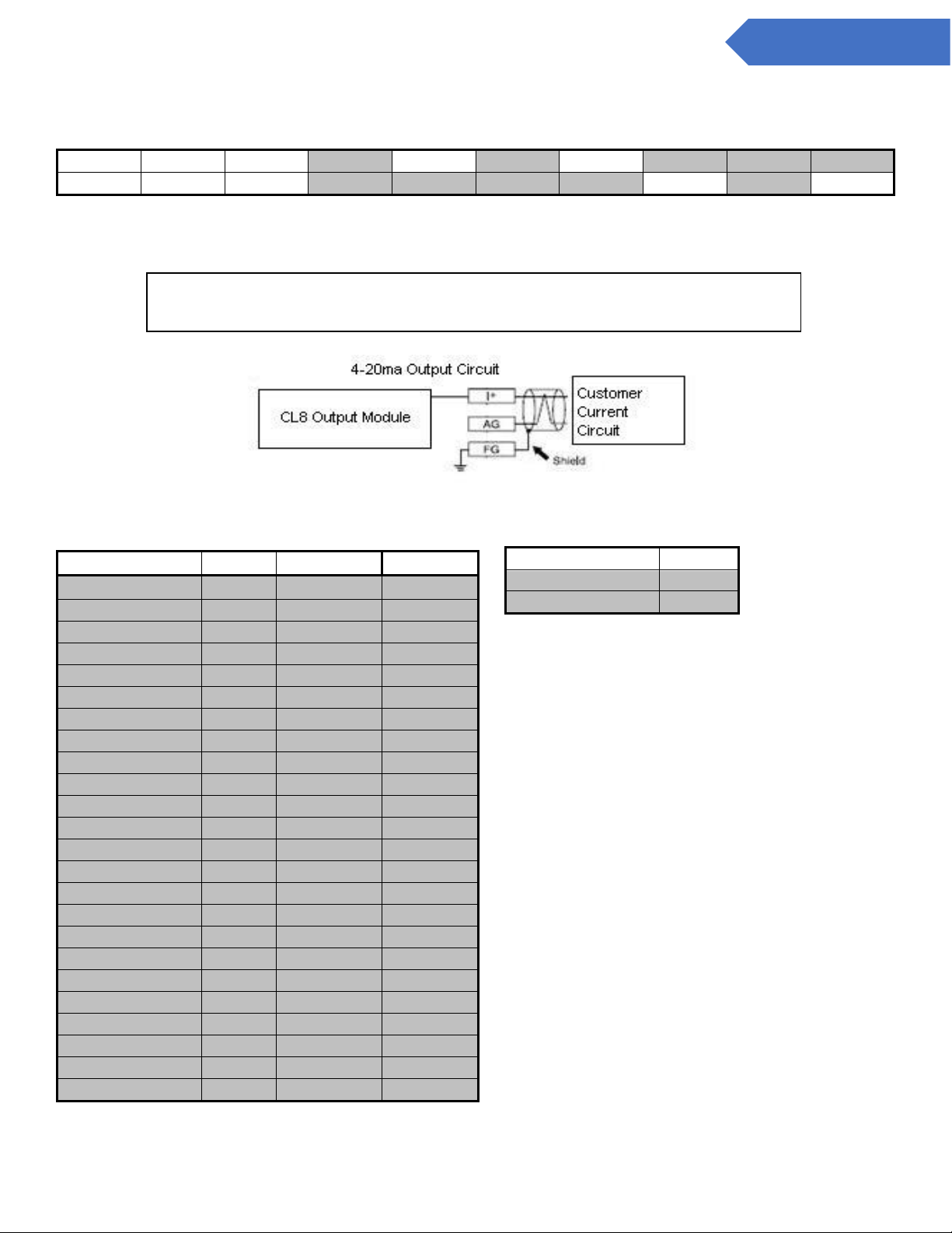
B.2 4 to 20mA Module (2 Points per Module) (PN: 2-500-011)
TR+
SLD
+24V
V1+
I1+
V2+
I2+
TR-
0V FG
AG1
FG
AG2
FG
Labeled connector on each 4 to 20ma Module.
4-20 ma Output Circuit Wiring.
Description
Module
Connection
Symbol
Point 1 4 to 20 ma
1
I1+
I+ 1
AG1
AG 1
FG
FG
Point 2 4 to 20 ma
1
I2+
I+ 1
AG2
AG 1
FG
FG
Point 3 4 to 20 ma
2
I3+
I+ 2
AG1
AG 2
FG
FG
Point 4 4 to 20 ma
2
I4+
I+ 2
AG2
AG 2
FG
FG
Point 5 4 to 20 ma
3
I1+
I+ 3
AG1
AG 3
FG
FG
Point 6 4 to 20 ma
3
I2+
I+ 3
AG2
AG 3
FG
FG
Point 7 4 to 20 ma
4
I3+
I+
4
AG1
AG 4
FG
FG
Point 8 4 to 20 ma
4
I4+
I+ 4
AG2
AG 4
FG
FG
Module
Address
Module 1
6
Module 2
8
Module 3
10
Module 4
12
IMPORTANT: Use only connections above shown in grey. Other connections are
pre-wired in the CL4/CL8.
Page 48
48
DC-ITD-CL4andCL8MAN01.A www.dodtec.com
NOV 2018 815-788-5200
CL4 & CL8 Manual
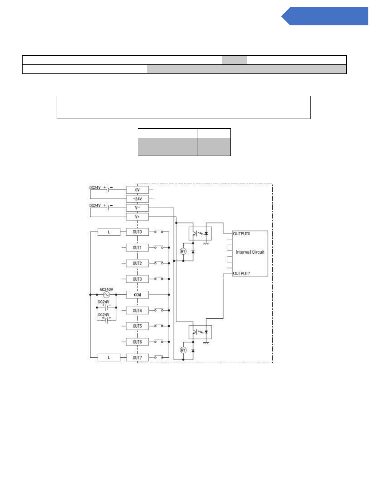
B.2.1 4 to 20mA Module (4 Points per Module) (PN: 2-500-011)
TR+
SLD
+24V
AG1
V2+
I2+
V3+
I3+
AG4
FG*
TR-
0V
V1+
I1+
AG2
FG*
AG3
V4+
I4+
GND
Labeled connector on each 4 to 20ma Module. *Each ‘FG’ terminal may be used for 2 points.
4-20 ma Output Circuit Wiring.
Description
Module
Connection
Symbol
Point 1 4 to 20 ma
1
I1+
I+ 1
AG1
AG 1
FG*
FG
Point 2 4 to 20 ma
1
I2+
I+ 1
AG2
AG 1
FG*
FG
Point 3 4 to 20 ma
1
I3+
I+ 1
AG3
AG 1
FG*
FG
Point 4 4 to 20 ma
1
I4+
I+ 1
AG4
AG 1
FG*
FG
Point 5 4 to 20 ma
2
I1+
I+ 2
AG1
AG 2
FG*
FG
Point 6 4 to 20 ma
2
I2+
I+ 2
AG2
AG 2
FG*
FG
Point 7 4 to 20 ma
2
I3+
I+ 2
AG3
AG 2
FG*
FG
Point 8 4 to 20 ma
2
I4+
I+
2
AG4
AG
2
FG*
FG
Module
Address
Module 1
9
Module 2
D
IMPORTANT: Use only connections above shown in grey. Other connections are
pre-wired in the CL4/CL8.
Page 49
49
DC-ITD-CL4andCL8MAN01.A www.dodtec.com
NOV 2018 815-788-5200
CL4 & CL8 Manual
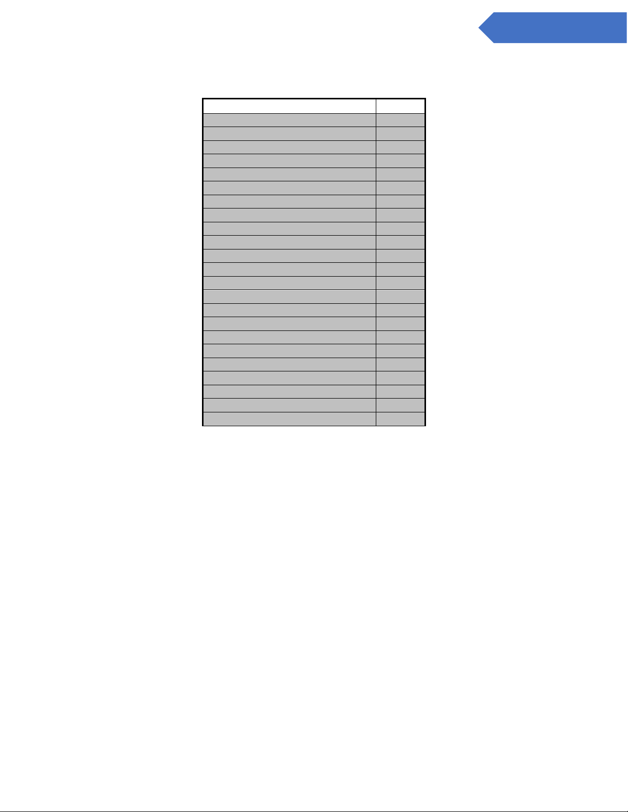
B.3 8-Point Module (PN: 2-500-012)
TR+
SLD
+24V
V+
COM
TR-
0V
V-
0 1 2 3 4 5 6
7
Labeled connector on each 8 Point Relay Module. See drawing below.
Module
Address
8 Point Relay
Module
7
IMPORTANT: Use only connections above shown in grey. Other connections are
pre-wired in the CL8.
Page 50
50
DC-ITD-CL4andCL8MAN01.A www.dodtec.com
NOV 2018 815-788-5200
CL4 & CL8 Manual
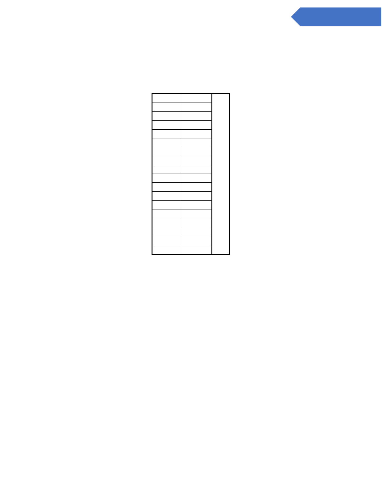
B.4 Optional Mechanical Relays
Description
Output
Point 1 Alarm Level 1
0
Point 1 Alarm Level 2
1
Point 2 Alarm Level 1
2
Point 2 Alarm Level 2
3
Point 3 Alarm Level 1
4
Point 3 Alarm Level 2
5
Point 4 Alarm Level 1
6
Point 4 Alarm Level 2
7
Point 5 Alarm Level 1
8
Point 5 Alarm Level 2
9
Point 6 Alarm Level 1
10
Point 6 Alarm Level 2
11
Point 7 Alarm Level 1
12
Point 7 Alarm Level 2
13
Point 8 Alarm Level 1
14
Point 8 Alarm Level 2
15
Critical Fault (Fault)
16
SPARE (UNUSED)
17
Power On
18
Analysis Mode (Out of Analysis)
19
General Fault (Maintenance)
20
Gas Alarm Level 1
21
Gas Alarm Level 2
22
NOTES
240 VAC max per relay
Xx Amps max current per relay
Page 51
51
DC-ITD-CL4andCL8MAN01.A www.dodtec.com
NOV 2018 815-788-5200
CL4 & CL8 Manual
B.4.1 Optional Mechanical Relay Wiring
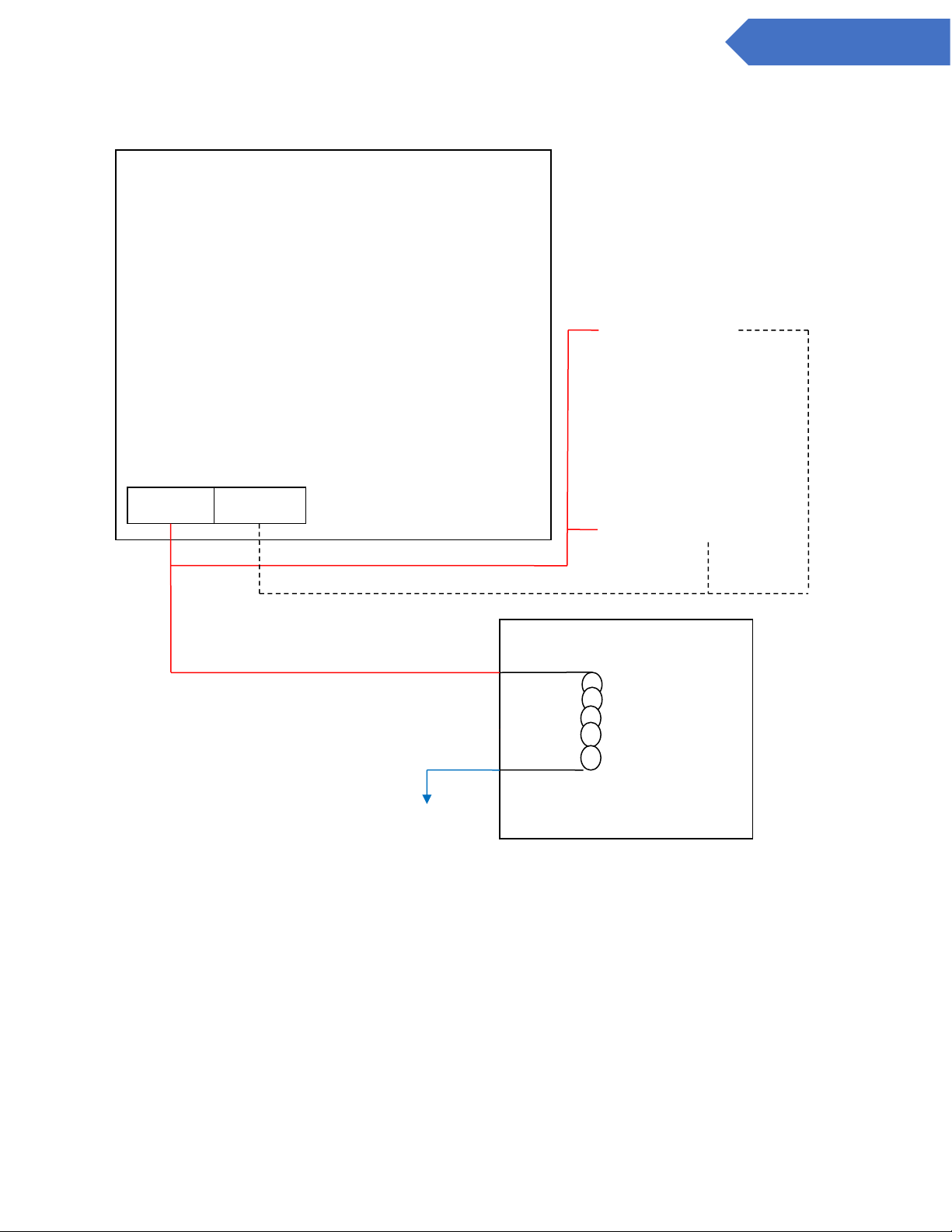
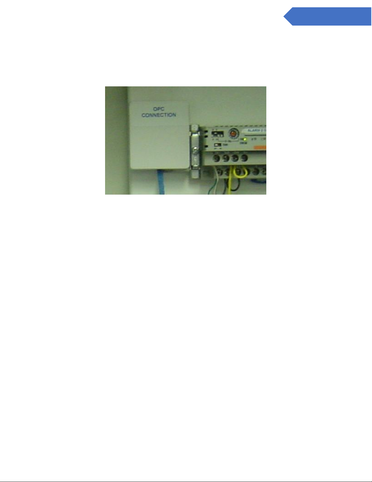
Below is a typical wiring diagram to connect a Form C Relay to any of the sinking outputs described in
Appendix Section B.1 Note: You must connect 24V + to both V1+ / V2+ AND connect 24V- to both V1-/ V2on the connector as shown below.
0
1
Output
2 3 4 5 6 7 8 9 10
11
12
13
14
15
V1 +
V1 -
16
17
18
19
20
21
22
23
24
25
26
27
28
29
30
31
V2 +
V2 -
Page 52
52
DC-ITD-CL4andCL8MAN01.A www.dodtec.com
NOV 2018 815-788-5200
CL4 & CL8 Manual
24 V+
24 V -
N/O
COMM
N/C
COIL
Form C Relay
A1
A2
DOD Customer
24V Sinking
Output Module
(See Section
Attach to
desired
output 0-31
on connector
Page 53
53
DC-ITD-CL4andCL8MAN01.A www.dodtec.com
NOV 2018 815-788-5200
CL4 & CL8 Manual
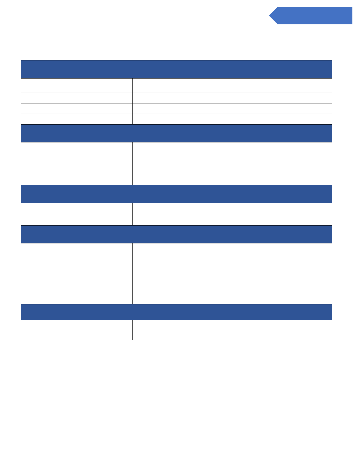
B.5 OPC Interface (PN: 2-500-501)
Use the RJ-45 connector pictured below to connect the CL4/CL8 to the I/P:network when the optional OPC
Interface (OPC I/F) is specified. The connector is located on the inside of the machine next to the top DINrail.
Page 54
54
DC-ITD-CL4andCL8MAN01.A www.dodtec.com
NOV 2018 815-788-5200
CL4 & CL8 Manual
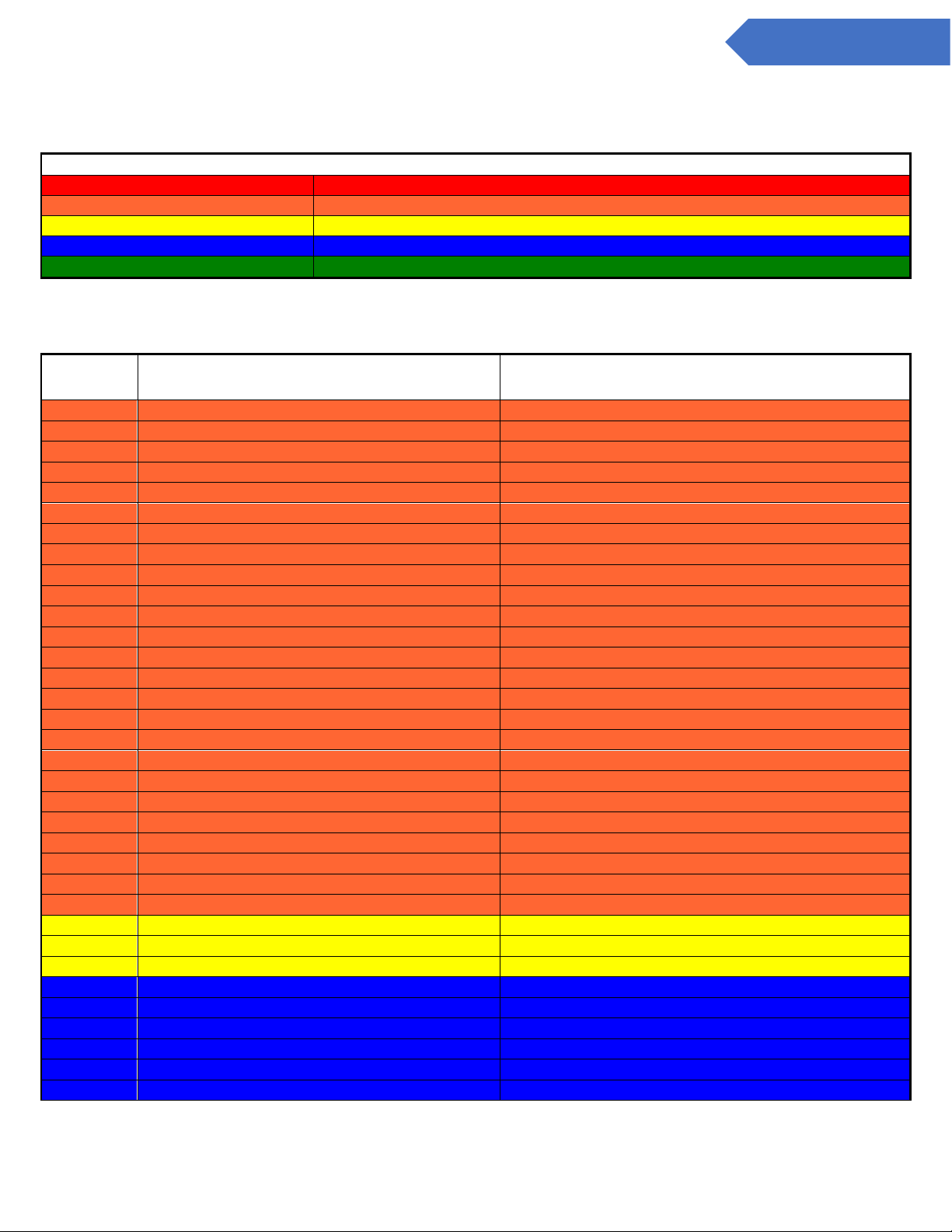
Appendix C – System Specifications
Physical Dimensions
Height
20”
Width
20”
Depth
11.3”
Weight
Approx. 70 lbs.
Tubing
Exhaust Line (1)
3/8” OD x 5/16” ID Polypropylene
(25 ft. max length)
Sample Lines (8)
1/ 4” OD x 3/16” ID Teflon FEP
(300 ft. max length)
Power
A/C Power
(100-120 VAC, 50/60 HZ)
( 220/240 VAC, 50/60 HZ)
Standard Output Relays
Rated Output Voltage
DC 24V
Rated Output Voltage Range
DC 20.4V - 28.8V
Maximum Load Voltage
0.2A/Connection (1.6A maximum pts 0-15 & pts 16)
Output Protection
None
Transport
Transport Times
Approx. 36 Seconds at 250 ft.
18 seconds at 125 ft.
Page 55
55
DC-ITD-CL4andCL8MAN01.A www.dodtec.com
NOV 2018 815-788-5200
CL4 & CL8 Manual
Appendix D – System Event Messages
COLOR CODING
RED
Gas Alarm
ORANGE
Service Fault (critical)
YELLOW
Maintenance (non-critical)
BLUE
Information Message
GREEN
Status (during analysis)
Event Code
Message
Corrective Action
30000
System Communication Failure
Service required
30001
All Points Are Disabled
Enable 1 or more points - sections 4.2.a
30002
Low flow multiple points
Check pump, gate, or adjust flow
30003
Gate Close Fault
Gate home switch stuck or gate not moving
30004
Gate open Fault
Check gate home switch and/or mechanism
30005
High background Fault
Check/replace tape
30006
I/O Failure - Check wiring
Check RS-485 wiring
30007
No Gas Family Selected
Service required
30008
Pump failure
Check pump wiring/flow
30009
Tape Advance Fault
Tape switch not activated before timeout
30010
Optic 1 Communication Error
Check Wiring or Optic 1
30011
Optic 2 Communication Error
Check Wiring or Optic 2
30012
High Background Tape Advance Fault
Check/replace tape
30013
LED Failure Optic 1
Possible Tape alignment problem
30014
Warning : Default values restored
Reconfigure & Calibrate
30015
Pump Timeout Error
Pump failure or system problem
30016
Tape Advance Problem
Service required
30017
Optic 1 LED Failure
Service required
30018
Optic 2 LED Failure
Service required
30019
Optic Supply Voltage Failure
Service required
30020
Optic reference validation fault
Service required
30021
LED Failure Optic 2
Service required
30022
Complete Optic Low Flow all Pt 1-4
Check gate closure
30023
Complete Optic Low Flow all Pt 5-8
Check gate closure
30024
LED Calibration error
50000
Chemlogic tape supply low
Change Tape
50001
Pt X High Flow
Flow Adjustment - Section 4.2.d
50009
Pt X Low Flow
Flow Adjustment - Section 4.2.d
60000
8 Hour - conc. detected
60010
Last analysis - Conc. detected
60011
Alarms & Faults Reset
60012
Error Transferring TWA/Analysis Summary
60013
Flow Fluctuation
60014
Maximum # of Ref fluctuations
Page 56
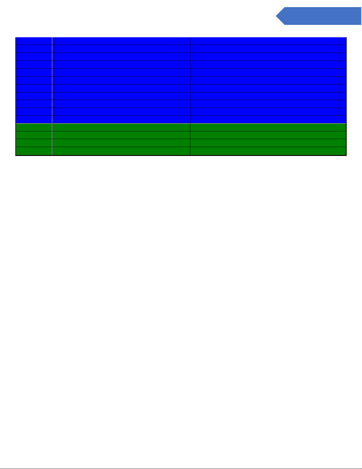
56
DC-ITD-CL4andCL8MAN01.A www.dodtec.com
NOV 2018 815-788-5200
CL4 & CL8 Manual
60015
LED Fluctuation fault
60016
Temperature fluctuation - O1
60017
Temperature fluctuation - O2
60018
K Factor - all pts = 1.000
60019
K Factor - some pts <> 1.000
60020
Reference fluctuation point X
60028
Power UP Time
60029
PT X Disabled
60030
Tape Counter Reset
60031
Simulation Mode
60032
Simulation Enabled Point 1
70000
DIAGNOSTIC STATUS OK
70001
8 Hour - no conc. all points.
70002
Analysis Start Time
70003
Last analysis - no Conc. found
Page 57
57
DC-ITD-CL4andCL8MAN01.A www.dodtec.com
NOV 2018 815-788-5200
CL4 & CL8 Manual
Appendix E – Gas Specifications
Family
Gas
Range
LDL
Full
Scale
Alarm
Level 1
Default
Alarm
Level 2
Default
Tape Part #
120 Day Ammonia
NH3
NH3(0-75)ppm
1.2
75
25
50
1-700-012
120 Day Hydrides
AsH3
AsH3(0-500)ppb
5.4
500
50
100
1-300-012
120 Day Hydrides
B2H6
B2H6(0-1000)ppb
6.0
1000
100
200
1-300-012
120 Day Hydrides
PH3
PH3(0-1500)ppb
4.9
1500
300
600
1-300-012
120 Day Hydrides
SiH4
SiH4(0-50)ppm
0.2
50 5 10
1-300-012
120 Day Hydrides
H2S
H2S(0-20)ppm
0.2
20
10
20
1-300-012
120 Day Hydrides
H2S
H2S(0-5)ppm
0.1 5 0.5 1 1-300-012
120 Day Hydrides
SiH4
SiH4(0-50)ppm
0.2
50 5 10
1-300-012
120 Day Phosgene
COCl2
COCl2(0-1000)ppb
8.9
1000
100
200
1-200-012
120 Day Phosgene
COCl2
COCl2(0-300)ppb
3.9
300
100
200
1-200-012
120 Day Phosgene
COCl2
COCl2(0-3250)ppb
8.8
3250
100
200
1-200-012
120 Day Phosgene
COCl2
COCl2(0-5000)ppb
8.8
5000
100
200
1-200-012
120 Mineral Acids
HCL
HCL(0-15)ppm
0.2
15 5 10
1-400-012
120 Mineral Acids
HF
HF(0-10)ppm
0.2
10 3 6
1-400-012
120 Mineral Acids
BF3
BF3(0-3200)ppb
72.2
3200
1000
2000
1-400-012
120 Mineral Acids
HBR
HBR(0-20)ppm
0.2
20 3 6
1-400-012
60 Day Hydrides
AsH3
AsH3(0-500)ppb
4.7
500
50
100
1-300-010
60 Day Hydrides
B2H6
B2H6(0-1000)ppb
31.5
1000
100
200
1-300-010
60 Day Hydrides
PH3
PH3(0-1500)ppb
8.4
1500
300
600
1-300-010
60 Day Hydrides
SiH4
SiH4(0-50)ppm
0.7
50 5 10
1-300-010
60 Day Hydrides
H2S
H2S(0-25)ppm
0.1
25
10
20
1-300-010
60 Day Mineral Acids
HCL
HCL(0-15)ppm
0.2
15 5 10
1-400-010
60 Day Mineral Acids
HF
HF(0-10)ppm
0.3
10 3 6
1-400-010
60 Day Mineral Acids
BF3
BF3(0-3200)ppb
72.1
3200
1000
2000
1-400-010
60 Day Mineral Acids
HBR
HBR(0-20)ppm
0.2
20 3 6
1-400-010
60 Day Phosgene
COCl2
COCl2(0-1000)ppb
8.9
1000
100
200
1-200-010
60 Day Phosgene
COCl2
COCl2(0-4000)ppb
8.9
4000
100
200
1-200-010
Acetic Acid
Acetic Acid
Acetic Acid(0-50) ppb
0.7
50
10
20
1-490-010
Bromine
Br2
Br2(0-1000)ppb
68.8
1000
100
200
1-490-062
Chlorine
CL2
CL2(0-2000)ppb
6.9
2000
500
1000
1-500-010
COS
COS
COS(0-20)ppm
0.9
20 5 10
1-300-062
HCN
HCN
HCN(0-2500)ppb
298.2
2500
500
1000
1-800-010
Hydrazine
N2H4
N2H4(0-500)ppb
4.3
500 5 10
1-D11-010
Low Level Chlorine
CL2
CL2(0-30)ppb
1.0
30 5 10
1-500-014
Low Level Hydrides
H2Se
H2Se(0-500)ppb
5.1
500
50
100
1-300-012
Low Level Hydrides
AsH3
AsH3(0-50)ppb
0.9
50 5 10
1-300-012
Low Level Hydrides
GeH4
GeH4(0-2000)ppb
62.1
2000
200
400
1-300-012
Page 58
58
DC-ITD-CL4andCL8MAN01.A www.dodtec.com
NOV 2018 815-788-5200
CL4 & CL8 Manual
Low Level Hydrides
PH3
PH3(0-300)ppb
4.8
300
50
100
1-300-012
MIC
MIC
MIC(0-100)ppm
3.7
100
10
20
1-600-010
NO2
NO2
NO2(0-100)ppm
0.3
100 3 6
1-600-511
Oxidizers
CL2
CL2(0-3200)ppb
50.1
3200
500
1000
1-550-010
Oxidizers
NO2
NO2(0-30)ppm
1.3
30 3 6
1-550-010
Oxidizers
F2
F2(0-3200)ppb
105.6
3200
1000
2000
1-550-010
Pyrolyzer - M/A
C5F8
C5F8(0-15)ppm
0.5
15 2 4
1-400-014
Pyrolyzer - M/A
NF3
NF3(0-15)ppm
0.5
15 2 4
1-400-014
Velcorin
DMDC
DMDC(0-200)ppb
8.8
200
40
80
1-200-030
Page 59
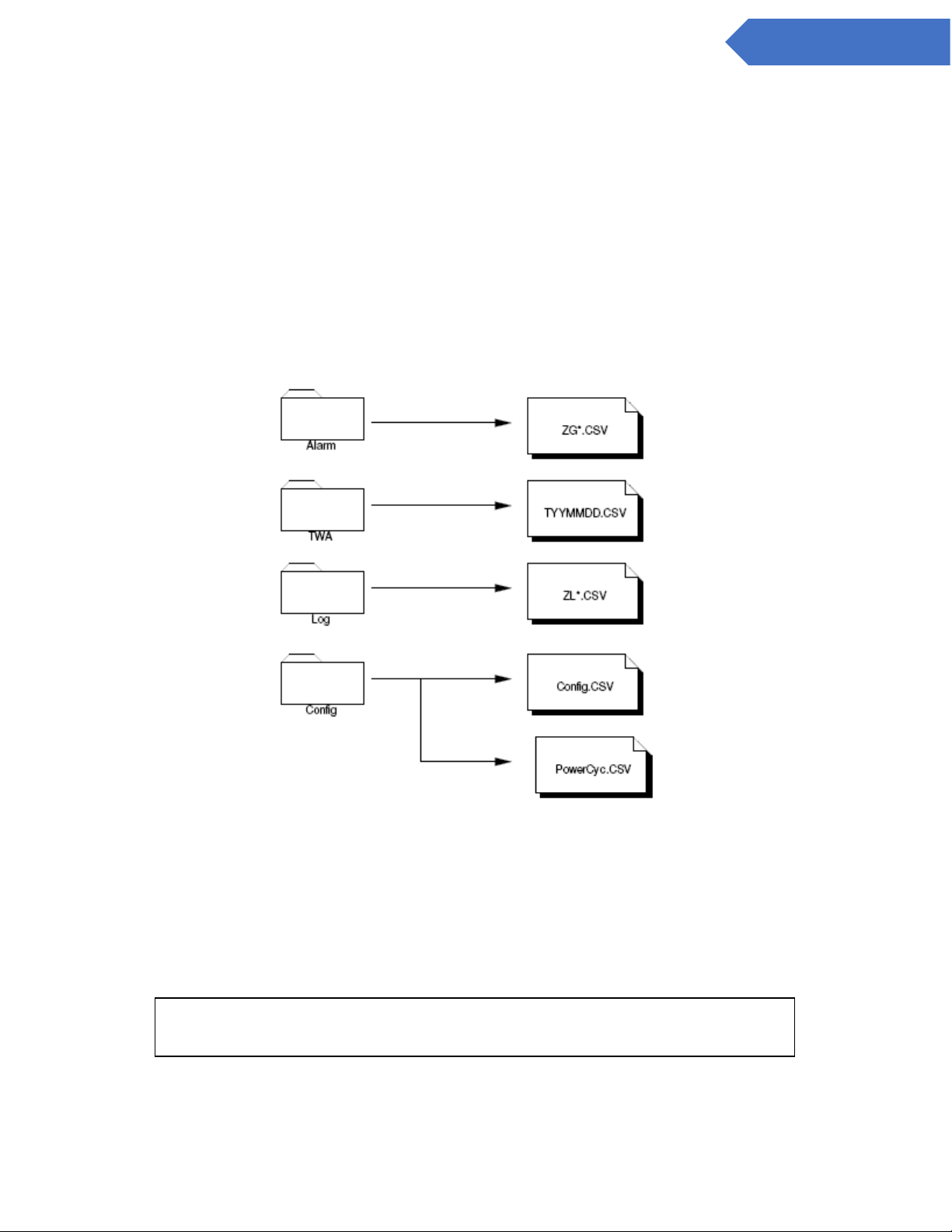
59
DC-ITD-CL4andCL8MAN01.A www.dodtec.com
NOV 2018 815-788-5200
CL4 & CL8 Manual
Appendix F – USB Memory Stick Data
To ensure that historical and performance information is stored properly be sure to insert a USB Memory
Stick in the proper slot at all times. See section 6.6 for installation instructions.
The USB Memory Stick stores all information in standard comma separated values (*.CSV) format for easy
access with any computer. Remove the USB Memory Stick from the CL4/CL8 as described in section 6.6 and
transfer the files to your personal computer*. The files are best viewed with programs that convert CSV
format to rows and columns (Microsoft Excel, OpenOffice, etc) but could be viewed with any standard text
editor.
Figure B.1 below shows the folders and files found on the USB Memory Stick depending on the configuration
or your CL4/CL8 and the use of the USB Memory Stick.
Figure B.1
F.1 Alarm & Event files (ZG*.CSV)
A portion of a typical event file when viewed with a spreadsheet program is shown below. Since the
messages are written in reverse chronological order the recovery time shown is above the time of occurrence
of the message.
NOTE : The columns labeled ‘Acknowledge Time’, ‘No. of Occ’, and ‘Acc Time’
are for DOD use only.
Page 60

60
DC-ITD-CL4andCL8MAN01.A www.dodtec.com
NOV 2018 815-788-5200
CL4 & CL8 Manual
Trigger
Date
Trigger
Time
Message(s)
Acknowledge
Time
Recovery
Time
No. of
occ.
Acc. time
Level
11/7/2006
17:32:00
8 Hour - no conc. all
points.
36
0:14:17 7
8 Hour - no conc. all
points.
9:32:20
36
0:14:17
7
11/7/2006
9:32:00
8 Hour - no conc. all
points.
36
0:14:17 7
8 Hour - no conc. all
points.
1:32:21
36
0:14:17
7
11/7/2006
1:32:00
8 Hour - no conc. all
points.
36
0:14:17 7
8 Hour - no conc. all
points.
17:32:32
36
0:14:17
7
11/6/2006
17:32:00
8 Hour - no conc. all
points.
36
0:14:17
7
11/6/2006
9:32:01
Analysis Start Time
13
35:13:06
7
F.2 TWA Data Logs (TYYMMDD.CSV)
The time weighted average information is stored on the USB Memory Stick in the TWA folder. A new file is
started each day (named with the year, month, and day) for easy retrieval. Below is a sample of one cycle
stored in a file.
DOD Technologies INC
http://www.dodtec.com
Analysis Cycle
4
Start Date/Time
4/11/2007
22:58
End Date/Time
4/12/2007
6:58
Analysis Time
8:00
Point 1 2 3 4 5 6 7 8
Gas
AsH3
AsH3
AsH3
AsH3
AsH3
AsH3
AsH3
AsH3
Avg Conc.
0
0 0 0 0 0 0 0
Peak Conc.
0
0 0 0 0 0 0 0
Peak 15 Min Avg. Conc.
0
0 0 0 0 0 0 0
Peak 15 Min Avg. Date
0
0 0 0 0 0 0 0
Peak 15 Min Avg. Time
0
0 0 0 0 0 0 0
F.3 Concentration Log Files (ZL*.CSV)
When gas is detected a log file is written to the USB Memory Stick (if installed) based on the configuration
settings – see section 4.5. Below is a sample of the file format stored on the USB Memory Stick - all 4/8
points are logged regardless of where the gas is detected.
Page 61

61
DC-ITD-CL4andCL8MAN01.A www.dodtec.com
NOV 2018 815-788-5200
CL4 & CL8 Manual
Date
Time 1 2 3 4 5 6 7 8
07/03/09
07:26:11 PM
0 0 1.2 0 0 0 0
0
07/03/09
07:26:13 PM
0 0 1.2 0 0 0 0
0
07/03/10
12:19:40 AM
0 0 1.2 0 0 0 0
0
07/03/10
12:19:42 AM
0 0 1.2 0 0 0 0
0
07/03/10
12:19:44 AM
0 0 1.6 0 0 0 0
0
07/03/10
12:19:46 AM
0 0 1.6 0 0 0 0
0
07/03/10
12:19:48 AM
0 0 2 0 0 0 0
0
F.4 Config File
A configuration file is created on the USB Memory Stick each time the ChemLogic 4/8 is powered on. The
config file stores basic information about the machine including version information, serial number, customer
name (if entered), etc. All of the information is stored in CSV format for easy viewing.
Page 62

62
DC-ITD-CL4andCL8MAN01.A www.dodtec.com
NOV 2018 815-788-5200
CL4 & CL8 Manual
Appendix G – ChemLogic Cassettes
DOD ChemLogic cassettes are designed for use in colorimetric based gas monitoring systems. Since this is
a particular end-use function and does not release or result in exposure to hazardous chemicals under
normal use Material Safety Data Sheets (MSDS) are not required.
ChemLogic cassettes are non-toxic and require no special precautions for protection.
However, contact with skin may cause the cassette to react, change color, and no longer be useful in your gas
monitoring system. We therefore recommend that rubber gloves be worn at all times while handling
including removal and installation. Always wash hands as a precaution after handling DOD ChemLogic
cassettes.
Page 63
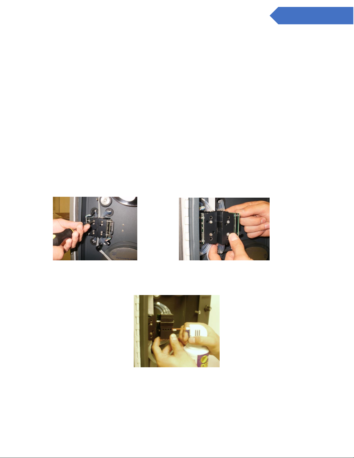
63
DC-ITD-CL4andCL8MAN01.A www.dodtec.com
NOV 2018 815-788-5200
CL4 & CL8 Manual
Appendix H – Optic Block Cleaning Procedure
The CL4/CL8 may require periodic cleaning of the optics block when the instrument is used in
environments with a high level of airborne particulate or a “High Background” Fault has been
reported.
There are two methods for cleaning the optics. One is a basic cleaning using canned air and the
other is a more in-depth cleaning that requires the fiber optics to be cleaned with alcohol.
In most cases the basic cleaning will be enough to clear an optics fault and return the DAC to normal
operating levels.
H.1 Basic Optics Cleaning
1) Exit analysis mode and go to the load tape screen.
2) Open the gate and remove the tape.
3) Remove the optic block covers and the four screws holding in the optic blocks. (Figure 1)
Figure 1 Figure 2
4) Pull block towards you until the pins holding the block in are loose (Figure 2)
5) Without removing any tubes, turn block so the bottom is facing out. (Figure 3)
Figure 3
6) Using canned air, blow out the channels on the block with high DAC values (Figure 3)
7) Re-Install the blocks and close the gate.
8) Press just below the top left corner in the load tape screen until the enter password screen appears.
(Figure 4)
Page 64
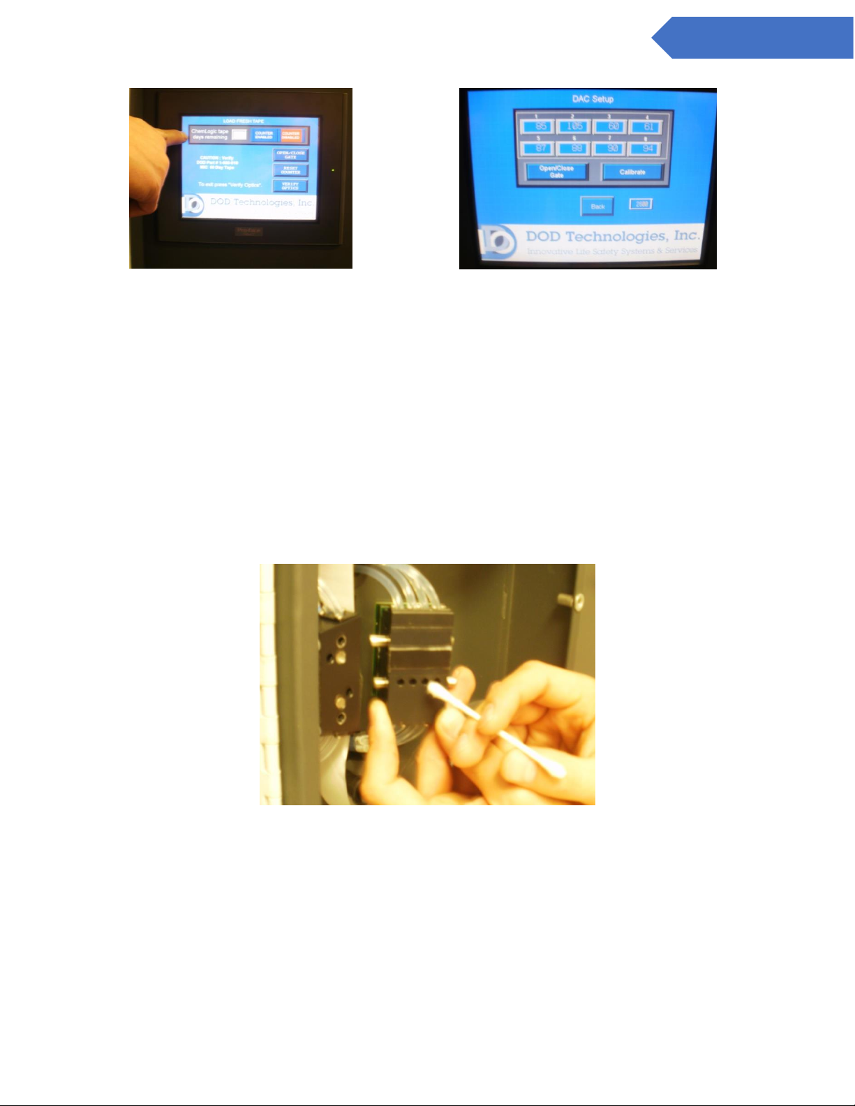
64
DC-ITD-CL4andCL8MAN01.A www.dodtec.com
NOV 2018 815-788-5200
CL4 & CL8 Manual
Figure 4 Figure 5
9) Enter 1225 for the password then press “Enter”.
10) You should see the calibrate optics screen (Figure 5), then make sure the gate is closed and press
“Calibrate”.
11) If the DAC values are 140 or below you are done. Go to “Main Menu” and clear the original faults and
re-enter analysis.
12) If the DAV values are not lower than 140, follow the advanced cleaning instructions below.
H.2 Advanced Optics Cleaning
1) Repeat above steps 1-5.
2) Using a cotton swab and alcohol (you may have to trim the cotton swab to fit) clean each channel that
has a DAC above 140. (Figure 6)
Figure 6
3) Repeat above steps 7-11
4) If the DAC values still have not improved contact CL4/CL8 technical support at (815)-788-5200
 Loading...