

Page 1

DR/DH TIRES/WHEELS 22 - 1
TIRES/WHEELS
TABLE OF CONTENTS
page page
TIRES/WHEELS
DIAGNOSIS AND TESTING
TIRE AND WHEEL RUNOUT ..............2
STANDARD PROCEDURE
MATCH MOUNTING ....................4
TIRE AND WHEEL BALANCE .............5
TIRE ROTATION .......................6
TIRES
DESCRIPTION
TIRES ...............................7
SPARE / TEMPORARY TIRE ..............8
RADIAL – PLY TIRES ...................8
TIRE PRESSURE FOR HIGH SPEEDS ......8
REPLACEMENT TIRES ..................8
TIRE INFLATION PRESSURES ............9
DIAGNOSIS AND TESTING
PRESSURE GAUGES ...................9
TIRE NOISE OR VIBRATION ..............9
TREAD WEAR INDICATORS .............10
TIRE WEAR PATTERNS ................10
TIRE/VEHICLE LEAD ...................10
STANDARD PROCEDURE
TIRE REPAIR AREA ....................12
CLEANING
TIRES ..............................12
SPECIFICATIONS
TIRE REVOLUTIONS PER MILE ..........12
WHEELS
DESCRIPTION
DESCRIPTION ........................13
WHEEL DESIGN ......................14
DIAGNOSIS AND TESTING
WHEEL INSPECTION ..................15
STANDARD PROCEDURE
WHEEL REPLACEMENT ................15
DUAL REAR WHEEL INSTALLATION .......17
SPECIFICATIONS
TORQUE CHART ......................18
STUDS
REMOVAL .............................18
INSTALLATION .........................19
WHEEL COVER
REMOVAL .............................19
INSTALLATION
REAR ..............................19
FRONT .............................20
SPARE TIRE
DESCRIPTION
SPARE / TEMPORARY TIRE .............20
FULL SIZE, SPARE WHEEL WITH
MATCHING TIRE ......................20
Page 2
22 - 2 TIRES/WHEELS DR/DH
TIRES/WHEELS
DIAGNOSIS AND TESTING
TIRE AND WHEEL RUNOUT
Radial runout is the difference between the high and
low points on the tire or wheel.
Lateral runout is the wobble of the tire or wheel.
Lateral runout of more than 2.0 mm (.080 inch) mea-
sured near the shoulder of the tire may cause the
vehicle to shake.
Page 3
DR/DH TIRES/WHEELS 22 - 3
Radial runout of more than 1.5 mm (.060 inch) measured at the center line of the tread may cause the
vehicle to shake.
Sometimes radial runout can be reduced. Relocate the
wheel and tire assembly on the mounting studs (See
Method 1). If this does not reduce runout to an
acceptable level, the tire can be rotated on the wheel.
(See Method 2).
METHOD 1 (RELOCATE WHEEL ON HUB)
1. Drive vehicle a short distance to eliminate tire flat spotting from a parked position.
2. Check wheel bearings and adjust if adjustable or replace if necessary.
3. Check the wheel mounting surface.
4. Relocate wheel on the mounting, two studs over from the original position.
5. Tighten wheel nuts until all are properly torqued, to eliminate brake distortion.
6. Check radial runout. If still excessive, mark tire sidewall, wheel, and stud at point of maximum runout and proceed to Method 2.
METHOD 2 (RELOCATE TIRE ON WHEEL)
NOTE: Rotating the tire on wheel is particularly effective when there is runout in both tire and wheel.
1. Remove tire from wheel and mount wheel on service dynamic balance machine.
2. Check the wheel radial runout.
Page 4
22 - 4 TIRES/WHEELS DR/DH
3. Check the wheel lateral runout.
• STEEL WHEELS: Radial runout 0.031 in., Lateral
runout 0.031 in. (maximum)
• ALUMINUM WHEELS: Radial runout 0.02 in.,
Lateral runout 0.025 in. (maximum)
4. If point of greatest wheel lateral runout is near original chalk mark, remount tire 180 degrees.
Recheck runout.
STANDARD PROCEDURE
MATCH MOUNTING
Wheels and tires are match mounted at the factory. This means that the high spot of the tire is matched to the low
spot on the wheel rim. Each are marked with a bright colored temporary label on the outboard surface for alignment.
The wheel is also marked permanently on the inside of the rim in the tire well. This permanent mark may be a paint
dot or line, a permanent label or a stamped impression such as an X. An optional location mark is a small spherical
indentation on the vertical face of the outboard flange on some non styled base steel wheels. The tire must be
removed to locate the permanent mark on the inside of the wheel.
Before dismounting a tire from its wheel, a reference mark should be placed on the tire at the valve stem location.
This reference will ensure that it is remounted in the original position on the wheel.
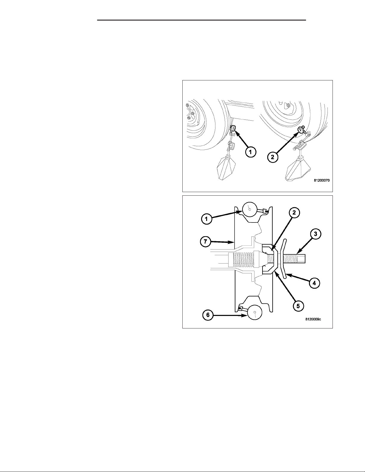
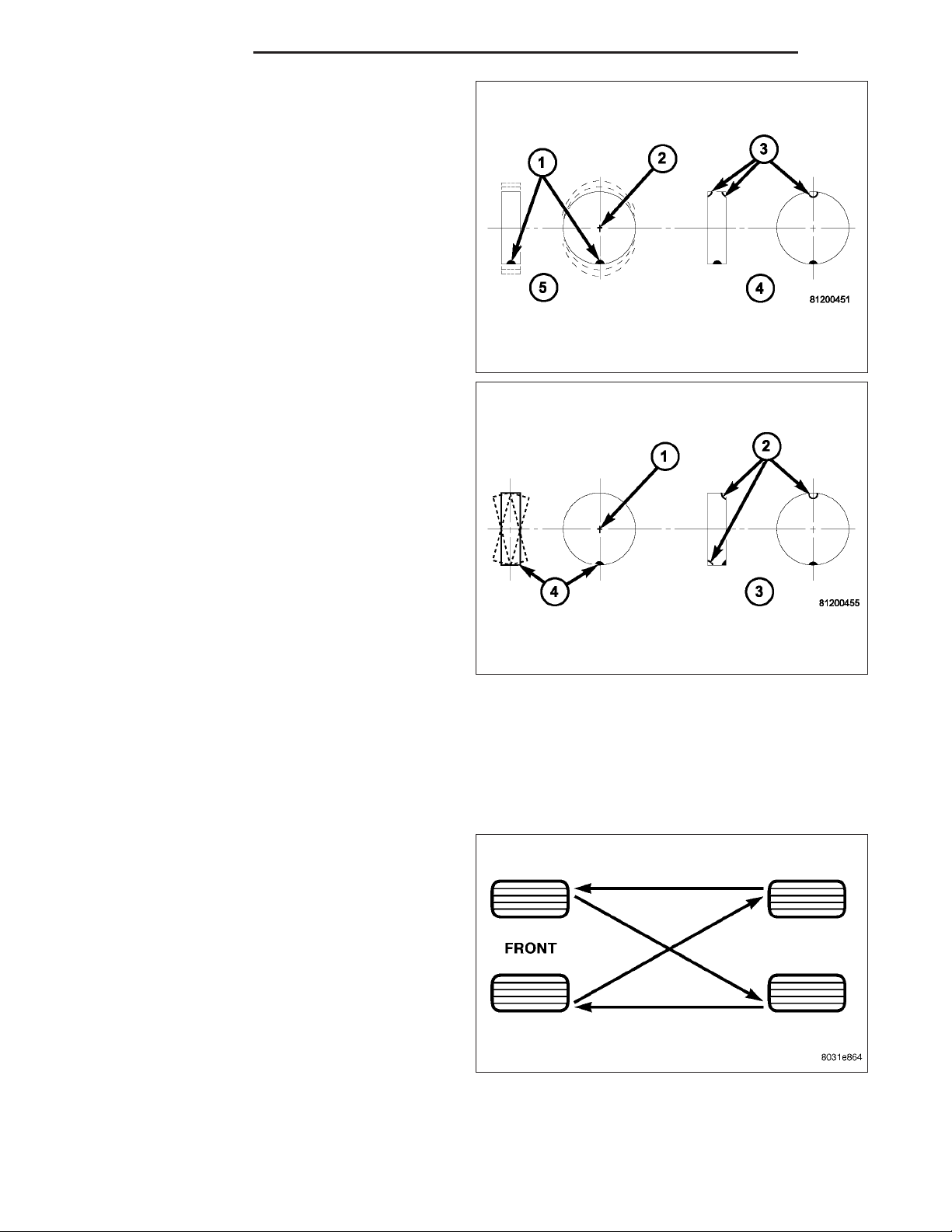
1. Remove the tire and wheel assembly from the
vehicle and mount on a service dynamic balance
machine.
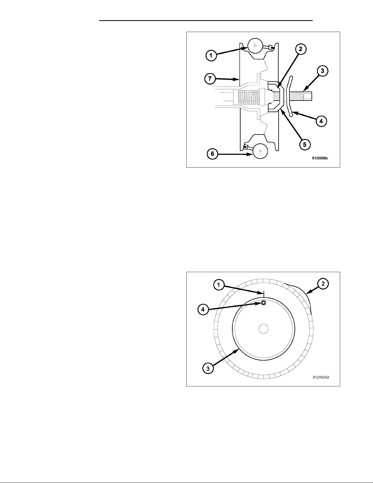
2. Measure the total runout on the center of the tire
tread rib (3) with a dial indicator. Record the indicator reading. Mark the tire to indicate the high
spot (2). Place a mark on the tire at the valve stem
(4) location (1).
Page 5
DR/DH TIRES/WHEELS 22 - 5
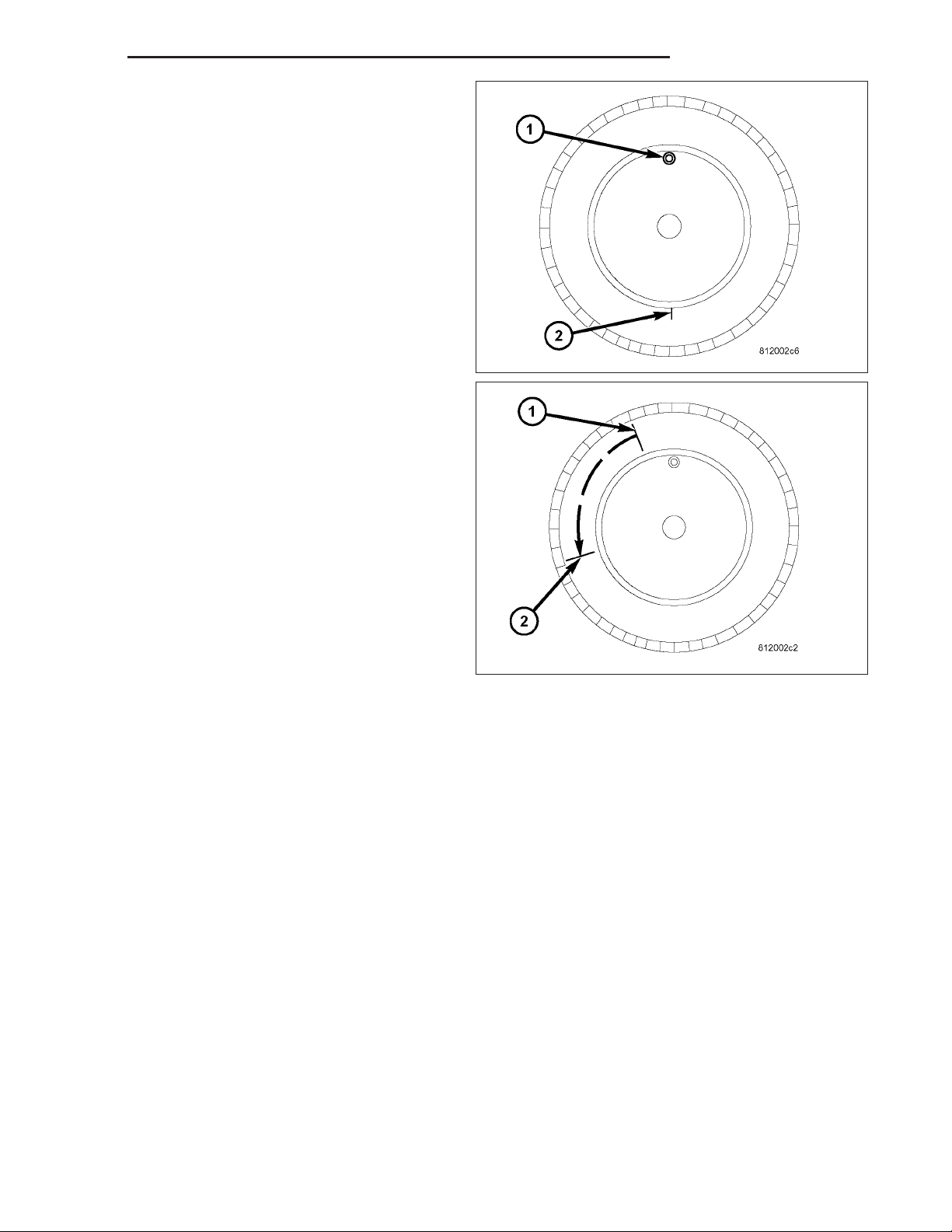
3. Break down the tire and remount it 180 degrees
on the rim (1)(2).
4. Measure the total indicator runout again. Mark the
tire to indicate the high spot.
5. If runout is still excessive, the following procedures
must be done.
• If the high spot is within 101.6 mm (4.0 in.) of the
first spot and is still excessive, replace the tire.
• If the high spot is within 101.6 mm (4.0 in.) of the
first spot on the wheel, the wheel may be out of
specifications. Refer to Wheel and Tire Runout.
• If the high spot is NOT within 101.6 mm (4.0 in.)
of either high spot, draw an arrow on the tread
from second high spot (1) to first (2). Break down
the tire and remount it 90 degrees on rim in that
direction. This procedure will normally reduce the
runout to an acceptable amount, if not replace
the rim.
TIRE AND WHEEL BALANCE
It is recommended that a two plane service dynamic balancer be used when a tire and wheel assembly require
balancing. Refer to balancer operation instructions for proper cone mounting procedures. Typically use front cone
mounting method for steel wheels. For aluminum wheel use back cone mounting method without cone spring.
NOTE: Static should be used only when a two plane balancer is not available.
NOTE: Cast aluminum and forged aluminum wheels require coated balance weights and special alignment
equipment.
Wheel balancing can be accomplished with either on or off vehicle equipment. When using on-vehicle balancing
equipment, remove the opposite wheel/tire. Off-vehicle balancing is recommended.
Page 6
22 - 6 TIRES/WHEELS DR/DH
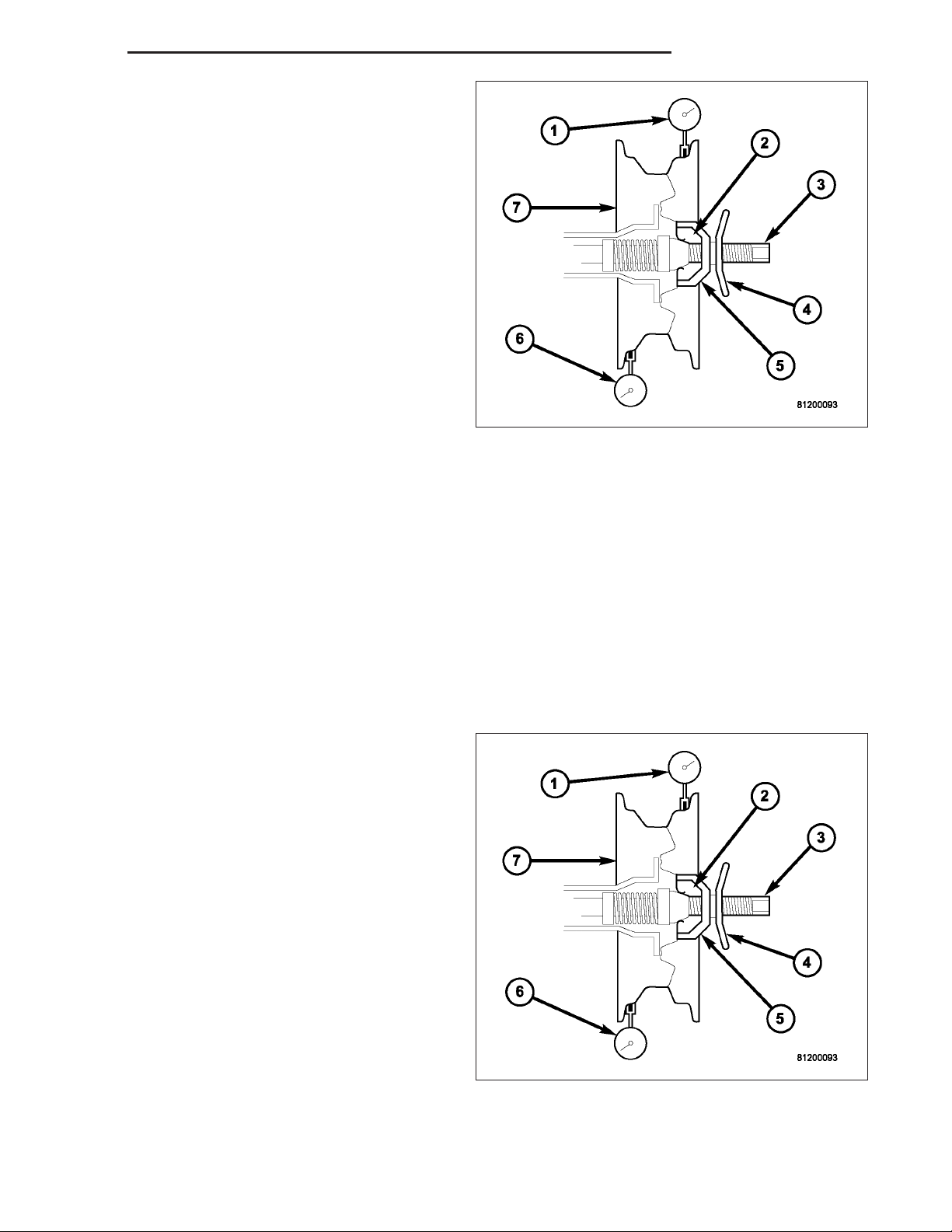
For static balancing, find the location of the heavy
spot (1) causing the imbalance (5). Counter balance
wheel directly opposite the heavy spot. Determine
weight required to counter balance the area of imbalance (4). Place half of this weight on the inner rim
flange (3) and the other half on the outer rim flange
(3).
For dynamic balancing (3), the balancing equipment is
designed to locate the amount of weight to be applied
to both the inner and outer rim flange (2).
TIRE ROTATION
Tires on the front and rear axles operate at different loads and perform different steering, driving, and braking functions. For these reasons, the tires wear at unequal rates. They may also develop irregular wear patterns. These
effects can be reduced by rotating the tires according to the maintenance schedule in the Owners Manual. This will
improve tread life, traction and maintain a smooth quiet ride.
The recommended method of tire rotation for single
rear wheel is. Other methods can be used, but may
not provide the same tire longevity benefits.
Page 7

DR/DH TIRES/WHEELS 22 - 7
CAUTION: 3500 Dual rear tires have a new tire
rotation pattern. This is to accommodate the outlined white letter (OWL) tires. When replacing a
flat, the spare tire may have to be remounted on
the rim or installed at a different location to maintain the correct placement of the outlined white
letter (OWL) tires.
The recommended method of tire rotation for dual rear
wheel is. Other methods can be used, but may not
provide the same tire longevity benefits.
TIRES
DESCRIPTION
TIRES
Tires are designed and engineered for each specific vehicle. They provide the best overall performance for normal
operation. The ride and handling characteristics match the vehicle’s requirements. With proper care they will give
excellent reliability, traction, skid resistance, and tread life.
Driving habits have more effect on tire life than any other factor. Careful drivers will obtain in most cases, much
greater mileage than severe use or careless drivers. A few of the driving habits which will shorten the life of any tire
are:
• Rapid acceleration
• Severe brake applications
• High speed driving
• Excessive speeds on turns
• Striking curbs and other obstacles
Radial-ply tires are more prone to irregular tread wear. It is important to follow the tire rotation interval (Refer to 22
- TIRES/WHEELS - STANDARD PROCEDURE). This will help to achieve a greater tread life.
TIRE IDENTIFICATION
Tire type, size, aspect ratio and speed rating are
encoded in the letters and numbers imprinted on the
side wall of the tire. Refer to the chart to decipher the
tire identification code.
Performance tires have a speed rating letter after the
aspect ratio number. The speed rating is not always
printed on the tire sidewall. These ratings are:
• Q up to 100 mph
• S up to 112 mph
• T up to 118 mph
• U up to 124 mph
• H up to 130 mph
• V up to 149 mph
• Z more than 149 mph (consult the tire manufac-
turer for the specific speed rating)
An All Season type tire will have either M+S,M&SorM–S(indicating mud and snow traction) imprinted on the
side wall.
Page 8

22 - 8 TIRES/WHEELS DR/DH
TIRE CHAINS
Tire snow chains may be used on certain models. Refer to the Owner’s Manual for more information.
SPARE / TEMPORARY TIRE
The temporary spare tire is designed for emergency use only. The original tire should be repaired or replaced at the
first opportunity, then reinstalled. Do not exceed speeds of 50 M.P.H. when using the temporary spare tire. Refer to
Owner’s Manual for complete details.
RADIAL – PLY TIRES
Radial-ply tires improve handling, tread life and ride quality, and decrease rolling resistance.
Radial-ply tires must always be used in sets of four. Under no circumstances should they be used on the front only.
They may be mixed with temporary spare tires when necessary. A maximum speed of 50 MPH is recommended
while a temporary spare is in use.
Radial-ply tires have the same load-carrying capacity as other types of tires of the same size. They also use the
same recommended inflation pressures.
The use of oversized tires, either in the front or rear of the vehicle, can cause vehicle drive train failure. This could
also cause inaccurate wheel speed signals when the vehicle is equipped with Anti-Lock Brakes.
The use of tires from different manufactures on the same vehicle is NOT recommended. The proper tire pressure
should be maintained on all four tires.
TIRE PRESSURE FOR HIGH SPEEDS
For proper tire pressure specification refer to the Owners Manual.
REPLACEMENT TIRES
The original equipment tires provide a proper balance of many characteristics such as:
• Ride
• Noise
• Handling
• Durability
• Tread life
• Traction
• Rolling resistance
• Speed capability
It is recommended that tires equivalent to the original equipment tires be used when replacement is needed.
Failure to use equivalent replacement tires may adversely affect the safety and handling of the vehicle.
The use of oversize tires may cause interference with vehicle components. Under extremes of suspension and
steering travel, interference with vehicle components may cause tire damage.
WARNING: FAILURE TO EQUIP THE VEHICLE WITH TIRES HAVING ADEQUATE SPEED CAPABILITY CAN
RESULT IN SUDDEN TIRE FAILURE.
Page 9

DR/DH TIRES/WHEELS 22 - 9
TIRE INFLATION PRESSURES
WARNING: OVER OR UNDER INFLATED TIRES
CAN AFFECT VEHICLE HANDLING AND TREAD
WEAR. THIS MAY CAUSE THE TIRE TO FAIL SUDDENLY, RESULTING IN LOSS OF VEHICLE CONTROL.
Under inflation will cause rapid shoulder wear (1), tire
flexing, and possible tire failure.
Over inflation will cause rapid center wear (1) reduction in the tire’s ability to cushion shocks.
Improper inflation can cause:
• Uneven wear patterns
• Reduced tread life
• Reduced fuel economy
• Unsatisfactory ride
• Vehicle drift
For proper tire pressure specification refer to the vehicles Owners Manual.
DIAGNOSIS AND TESTING
PRESSURE GAUGES
A quality air pressure gauge is recommended to check tire pressure. After checking the air pressure, replace valve
cap finger tight.
TIRE NOISE OR VIBRATION
Radial-ply tires are sensitive to force impulses caused by improper mounting, vibration, wheel defects, or possibly
tire imbalance.
To find out if tires are causing the noise or vibration, drive the vehicle over a smooth road at varying speeds. Note
the noise level during acceleration and deceleration. The engine, differential and exhaust noises will change as
speed varies, while the tire noise will usually remain constant.
Page 10

22 - 10 TIRES/WHEELS DR/DH
TREAD WEAR INDICATORS
Tread wear indicators (3) are molded into the bottom
of the tread grooves. When tread depth is 1.6 mm
(1/16 in.), the tread wear indicators (3) will appear as
a 13 mm (1/2 in.) band.
Tire replacement is necessary when indicators appear
in two or more grooves or if localized balding occurs.
TIRE WEAR PATTERNS
Under inflation will cause wear on the shoulders of tire. Over inflation will cause wear at the center of tire.
Excessive camber causes the tire to run at an angle to the road. One side of tread is then worn more than the
other.
Excessive toe-in or toe-out causes wear on the tread edges and a feathered effect across the tread.
TIRE/VEHICLE LEAD
Use the following Vehicle Lead Diagnosis And Correction Chart to diagnose and correct a vehicle lead or drift
problem.
Page 11

DR/DH TIRES/WHEELS 22 - 11
Page 12

22 - 12 TIRES/WHEELS DR/DH
STANDARD PROCEDURE
TIRE REPAIR AREA
For proper repairing, a radial tire must be removed
from the wheel. Repairs should only be made if the
defect, or puncture, is in the tread area (1). The tire
should be replaced if the puncture is located in the
sidewall.
Deflate tire completely before removing the tire from
the wheel. Use lubrication such as a mild soap solution when dismounting or mounting tire. Use tools free
of burrs or sharp edges which could damage the tire
or wheel rim.
Before mounting tire on wheel, make sure all rust is
removed from the rim bead and repaint if necessary.
Install wheel on vehicle, and tighten to proper torque
specification.
CLEANING
TIRES
Remove the protective coating on the tires before delivery of a vehicle. This coating may cause deterioration of the
tires.
To remove the protective coating, apply warm water and let it soak for a few minutes. Afterwards, scrub the coating
away with a soft bristle brush. Steam cleaning may also be used to remove the coating.
NOTE: DO NOT use gasoline, mineral oil, oil-based solvent or a wire brush for cleaning.
SPECIFICATIONS
TIRE REVOLUTIONS PER MILE
TIRE SIZE SUPPLIER REVOLUTIONS PER MILE
P245/70R17
WRANGLER SRA
LT245/70R17
LTX A/S
LT265/70R17E
LTX A/S
LT245/70R17
RUGGED TRAIL T/A
LT265/70R17E
RUGGED TRAIL T/A
LT285/70R17D
ALL TERRAIN T/A
P265/70R17
WRANGLER SR/A
P265/70R17
WRANGLER GS/A
LT275/70R17E
WRANGLER AT/S
GOODYEART 685
MICHELINT
MICHELINT 657
BF GOODRICHT
BF GOODRICHT
BF GOODRICHT
GOODYEART 657
GOODYEART 661
GOODYEART 649
675
684
658
632
Page 13

DR/DH TIRES/WHEELS 22 - 13
TIRE SIZE SUPPLIER REVOLUTIONS PER MILE
LT275/70R17E
TTL
P275/55R20
EAGLE LS
P275/60R20
WRANGLER HP
LT235/80R17E
WRANGLER SRA
LT235/80R17E
WRANGLER GSA
LT235/80R17E
AMERITRAC
LT235/80R17E
AMERITRAC TR
305/40ZR22
SCORPION ZERO
STANDARD CAB
SRT-10
USES A
3 SEASON TIRE
305/40ZR22
SCORPION ZERO
QUAD CAB
SRT-10
IDENTIFIED WITH A
9QC9 AT THE END OF THE DOT
CODE
IS A
4 SEASON TIRE
GOODYEART 649
GOODYEART 655
GOODYEART 636
GOODYEART
GOODYEART
GENERALT
GENERALT
PIRELLIT
PIRELLIT
649
649
649
648
654
654
WHEELS
DESCRIPTION
DESCRIPTION
Original equipment wheels are designed for the specified Maximum Vehicle Capacity.
All models use steel or aluminum drop center wheels.
Aluminum wheels require special balance weights and alignment equipment.
Page 14

22 - 14 TIRES/WHEELS DR/DH
1. On vehicles equipped with dual rear wheels, The
rim is an eight stud hole pattern wheel. The wheels
have a flat mounting surface (1).
2. The slots (1) in the wheel must be aligned to provide access to the valve stem.
WHEEL DESIGN
The rim size is on the vehicle safety certification label
located on the drivers door shut face. The size of the
rim is determined by the drivetrain package. Original
equipment wheels/rims are designed for operation up
to the specified maximum vehicle capacity.
All models use stamped steel, cast aluminum or
forged aluminum wheels. Every wheel has raised sections between the rim flanges (1) and rim drop well (3)
called safety humps.
Initial inflation of the tire forces the bead over these
raised sections. In case of rapid loss of air pressure,
the raised sections help hold the tire on the wheel.
The wheel studs and nuts are designed for specific
applications. All aluminum and some steel wheels
have wheel stud nuts with an enlarged nose. This
enlarged nose is necessary to ensure proper retention
of the wheels. Do not use replacement studs or nuts with a different design or lesser quality.
Page 15

DR/DH TIRES/WHEELS 22 - 15
DIAGNOSIS AND TESTING
WHEEL INSPECTION
Inspect wheels for:
• Excessive run out
• Dents or cracks
• Damaged wheel lug nut holes
• Air Leaks from any area or surface of the rim
NOTE: Do not attempt to repair a wheel by hammering, heating or welding.
If a wheel is damaged an original equipment replacement wheel should be used. When obtaining replacement
wheels, they should be equivalent in load carrying capacity. The diameter, width, offset, pilot hole and bolt circle of
the wheel should be the same as the original wheel.
WARNING: FAILURE TO USE EQUIVALENT REPLACEMENT WHEELS MAY ADVERSELY AFFECT THE
SAFETY AND HANDLING OF THE VEHICLE. USED WHEELS ARE NOT RECOMMENDED. THE SERVICE HISTORY OF THE WHEEL MAY HAVE INCLUDED SEVERE TREATMENT OR VERY HIGH MILEAGE. THE RIM
COULD FAIL WITHOUT WARNING.
STANDARD PROCEDURE
WHEEL REPLACEMENT
The wheel studs and nuts are designed for specific applications. They must be replaced with equivalent parts. Do
not use replacement parts of lesser quality or a substitute design. All aluminum and some steel wheels have wheel
stud nuts which feature an enlarged nose. This enlarged nose is necessary to ensure proper retention of the aluminum wheels.
NOTE: Do not use chrome plated lug nuts with
chrome plated wheels.
NOTE: All wheel nuts should then be tightened
just snug. Gradually tighten them in sequence to
the proper torque specification.
NOTE: Never use oil or grease on studs or nuts.
Before installing the wheel, be sure to remove any
build up of corrosion on the wheel mounting surfaces.
Ensure wheels are installed with good metal-to-metal
contact. Improper installation could cause loosening of
wheel nuts. This could affect the safety and handling
of your vehicle.
To install the wheel (3), first position it properly on the mounting surface.
Page 16

22 - 16 TIRES/WHEELS DR/DH
8–lug.
(SRT-10).
6– bolt pattern.
Wheels must be replaced if they have:
• Excessive runout
• Bent or dented
• Leak air through welds
• Have damaged bolt holes
Page 17

DR/DH TIRES/WHEELS 22 - 17
Wheel repairs employing hammering, heating, or welding are not allowed.
Original equipment wheels are available through your dealer. Replacement wheels from any other source should be
equivalent in:
• Load carrying capacity
• Diameter
• Width
• Offset
• Mounting configuration
Failure to use equivalent replacement wheels may affect the safety and handling of your vehicle. Replacement with
used wheels is not recommended. Their service history may have included severe treatment.
DUAL REAR WHEEL INSTALLATION
Dual rear wheels use a special heavy duty lug nut wrench. It is recommended to remove and install dual rear
wheels only when the proper wrench is available. The wrench is also use to remove wheel center caps for more
information refer to Owner’s Manual.
The tires on both wheels must be completely raised off the ground when tightening the lug nuts. This will ensure
correct wheel centering and maximum wheel clamping.
A two piece flat face lug nut with right-hand threads is
used for retaining the wheels on the hubs.
The dual rear wheel lug nuts should be tightened
according to the following procedure:
NOTE: Do not use more then two drops of oil on
the nut/washer (1), since the center caps attach in
this area.
• Place two drops of oil to the interface of the nut/
washer (1) before installing on the wheel stud.
• Tighten the wheel lug nuts in the numbered sequential pattern until they are snug tight. Then tighten lug nut to
specified torque following same number sequence, (Refer to 22 - TIRES/WHEELS/WHEELS - SPECIFICATIONS).
• Tighten lug nuts in same numbered sequence a second time to the specified torque. This will ensure that the
wheels are thoroughly mated.
• Check lug nut specified torque after 100 miles (160 kilometers). Also after 500 miles (800 kilometers) of vehicle
operation.
NOTE: Wheel lug nuts should be tightened to specified torque at every maintenance interval thereafter.
Page 18

22 - 18 TIRES/WHEELS DR/DH
SPECIFICATIONS
TORQUE CHART
TORQUE SPECIFICATIONS
DESCRIPTION N·m Ft. Lbs. In. Lbs.
1500 Series
Lug Nut 9/16 X 18 with
60° Cone
LD
2500 Series
Lug Nut 9/16 X 18 with
60° Cone
HD SRW
3500 Series
Lug Nut 9/16 X 18 with
Flat Washer
HD DRW
129 95 —
197 145 —
210 155 —
STUDS
REMOVAL
1. Raise and support the vehicle.
2. Remove the wheel and tire assembly.
3. Remove the brake caliper, caliper adapter and
rotor, (Refer to 5 - BRAKES/HYDRAULIC/MECHANICAL/ROTORS - REMOVAL).
4. Remove the wheel speed sensor from the hub.
5. Press the stud from the hub using special tool
C-4150A (1).
6. Remove the stud (2) from the hub (1) through the
backing plate access hole (3).
Page 19

DR/DH TIRES/WHEELS 22 - 19
INSTALLATION
1. Install the new stud (2) into the hub flange (1).
2. Install three proper sized washers onto the stud,
then install lug nut with the flat side of the nut
against the washers.
3. Tighten the lug nut until the stud is pulled into the
hub flange. Verify that the stud is properly seated
into the flange.
4. Remove the lug nut and washers.
5. Install the brake rotor, caliper adapter, and caliper,
(Refer to 5 - BRAKES/HYDRAULIC/MECHANICAL/
ROTORS - INSTALLATION).
6. Install the wheel speed sensor.
7. Install the wheel and tire assembly, use new lug nut on the stud or studs that were replaced.
8. Remove the support and lower the vehicle.
WHEEL COVER
REMOVAL
NOTE: The hub caps must be removed before raising the vehicle off the ground.
NOTE: You must use the flat end of the hub/cap remover/installer combination tool to pry off the wheel
skins. Insert the flat tip completely and using a back and forth motion, loosen the wheel skin. repeat this
procedure around the tire until the wheel skin pops off.
1. On 2500/3500 single rear wheel (SRW) models, insert a hub/cap remover/installer combination tool using the
blade on the end of the tool to pry the cap off in a back and forth motion.
2. On 3500 models with dual rear wheels (DRW), you must first remove the hub caps. The hub/cap remover/installer combination tool must be inserted in the pry off notch of the rear hub caps.
3. Position the hub/cap remover/installer combination tool and pull out on the tool firmly. The cap should come off.
4. The wheel skins can now be removed from the wheel.
5. On 3500 models front hub caps use the hub/cap remover/installer combination tool to pry off the cap in a back
and forth motion. The wheel skins can now be removed.
INSTALLATION
REAR
1. Install one 1 1/2 in. valve stem extension on each rear inner wheel.
NOTE: A 3/8 in. drive 10mm deep wheel socket with a 10 in. or greater extension can be used to remove the
existing valve stem cap and install the extension.
2. Install one 1 in. valve stem extension on each outer wheel.
3. Align the cooling windows of the wheel skin with the cooling windows of the wheel. Seat one side of the wheel
skin’s retainer onto the wheel. Using a rubber mallet, strike thew wheel skin on the outer circumference. Strike at
several locations around the circumference until the skin is fully seated.
Page 20

22 - 20 TIRES/WHEELS DR/DH
NOTE: The wheel skin and the hub cap are fully seated when there is a consistent gap between the skin/cap
and the wheel.
4. Tug on the hub/cap wheel skin to ensure that they are properly installed.
FRONT
1. Align the valve stem with the notch in the wheel skin.
2. Seat on side of the wheel skin’s wire retainer on to the wheel.
3. Using a rubber mallet, strike the opposite side of the wheel skin until the skin is properly seated.
NOTE: The wheel skin and the hub cap are fully seated when there is a consistant gap between the skin/
cap and the wheel.
4. Tug on the hub cap/wheel skin to ensure that they are properly installed.
SPARE TIRE
DESCRIPTION
SPARE / TEMPORARY TIRE
The temporary spare tire is designed for emergency use only. The original tire should be repaired or replaced at the
first opportunity, then reinstalled. Do not exceed speeds of 50 M.P.H. when using the temporary spare tire. Refer to
Owner’s Manual for complete details.
FULL SIZE, SPARE WHEEL WITH MATCHING TIRE
The spare is a full usage wheel with a matching tire, It can be used within the (posted legal) speed limits or distance
limitations as of the rest of the vehicles four tires. Refer to Owner’s Manual for complete details.
 Loading...