


Dodge Tires 3500 2005, Tires 2500 2005, Tires 1500 2005 Service Manual

DR/DH TIRES/WHEELS 22 - 1
TIRES/WHEELS
TABLE OF CONTENTS
page page
TIRES/WHEELS
DIAGNOSIS AND TESTING
TIRE AND WHEEL RUNOUT ..............2
STANDARD PROCEDURE
MATCH MOUNTING ....................4
TIRE AND WHEEL BALANCE .............5
TIRE ROTATION .......................6
TIRES
DESCRIPTION
TIRES ...............................7
SPARE / TEMPORARY TIRE ..............8
RADIAL – PLY TIRES ...................8
TIRE PRESSURE FOR HIGH SPEEDS ......8
REPLACEMENT TIRES ..................8
TIRE INFLATION PRESSURES ............9
DIAGNOSIS AND TESTING
PRESSURE GAUGES ...................9
TIRE NOISE OR VIBRATION ..............9
TREAD WEAR INDICATORS .............10
TIRE WEAR PATTERNS ................10
TIRE/VEHICLE LEAD ...................10
STANDARD PROCEDURE
TIRE REPAIR AREA ....................12
CLEANING
TIRES ..............................12
SPECIFICATIONS
TIRE REVOLUTIONS PER MILE ..........12
WHEELS
DESCRIPTION
DESCRIPTION ........................13
WHEEL DESIGN ......................14
DIAGNOSIS AND TESTING
WHEEL INSPECTION ..................15
STANDARD PROCEDURE
WHEEL REPLACEMENT ................15
DUAL REAR WHEEL INSTALLATION .......17
SPECIFICATIONS
TORQUE CHART ......................18
STUDS
REMOVAL .............................18
INSTALLATION .........................19
WHEEL COVER
REMOVAL .............................19
INSTALLATION
REAR ..............................19
FRONT .............................20
SPARE TIRE
DESCRIPTION
SPARE / TEMPORARY TIRE .............20
FULL SIZE, SPARE WHEEL WITH
MATCHING TIRE ......................20
22 - 2 TIRES/WHEELS DR/DH
TIRES/WHEELS
DIAGNOSIS AND TESTING
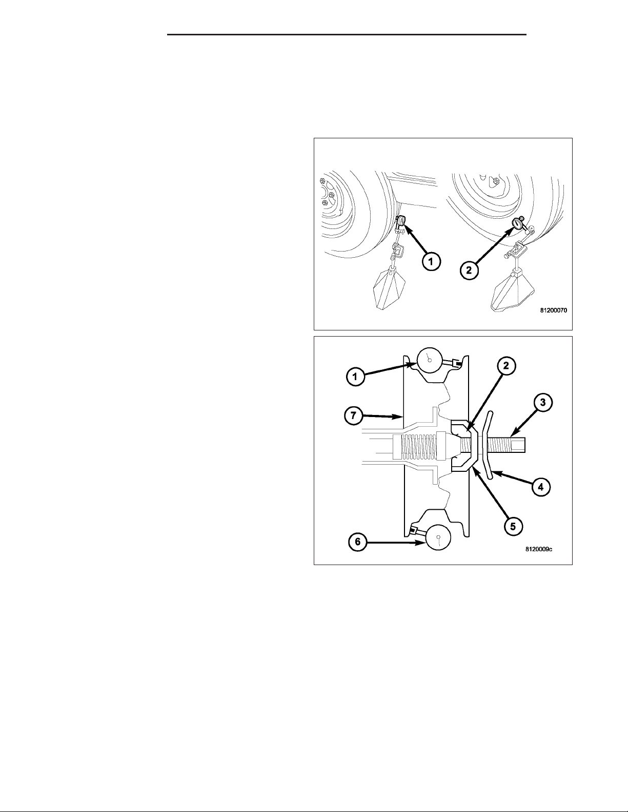
TIRE AND WHEEL RUNOUT
Radial runout is the difference between the high and
low points on the tire or wheel.
Lateral runout is the wobble of the tire or wheel.
Lateral runout of more than 2.0 mm (.080 inch) mea-
sured near the shoulder of the tire may cause the
vehicle to shake.
DR/DH TIRES/WHEELS 22 - 3
Radial runout of more than 1.5 mm (.060 inch) measured at the center line of the tread may cause the
vehicle to shake.
Sometimes radial runout can be reduced. Relocate the
wheel and tire assembly on the mounting studs (See
Method 1). If this does not reduce runout to an
acceptable level, the tire can be rotated on the wheel.
(See Method 2).
METHOD 1 (RELOCATE WHEEL ON HUB)
1. Drive vehicle a short distance to eliminate tire flat spotting from a parked position.
2. Check wheel bearings and adjust if adjustable or replace if necessary.
3. Check the wheel mounting surface.
4. Relocate wheel on the mounting, two studs over from the original position.
5. Tighten wheel nuts until all are properly torqued, to eliminate brake distortion.
6. Check radial runout. If still excessive, mark tire sidewall, wheel, and stud at point of maximum runout and proceed to Method 2.
METHOD 2 (RELOCATE TIRE ON WHEEL)
NOTE: Rotating the tire on wheel is particularly effective when there is runout in both tire and wheel.
1. Remove tire from wheel and mount wheel on service dynamic balance machine.
2. Check the wheel radial runout.
22 - 4 TIRES/WHEELS DR/DH
3. Check the wheel lateral runout.
• STEEL WHEELS: Radial runout 0.031 in., Lateral
runout 0.031 in. (maximum)
• ALUMINUM WHEELS: Radial runout 0.02 in.,
Lateral runout 0.025 in. (maximum)
4. If point of greatest wheel lateral runout is near original chalk mark, remount tire 180 degrees.
Recheck runout.
STANDARD PROCEDURE
MATCH MOUNTING
Wheels and tires are match mounted at the factory. This means that the high spot of the tire is matched to the low
spot on the wheel rim. Each are marked with a bright colored temporary label on the outboard surface for alignment.
The wheel is also marked permanently on the inside of the rim in the tire well. This permanent mark may be a paint
dot or line, a permanent label or a stamped impression such as an X. An optional location mark is a small spherical
indentation on the vertical face of the outboard flange on some non styled base steel wheels. The tire must be
removed to locate the permanent mark on the inside of the wheel.
Before dismounting a tire from its wheel, a reference mark should be placed on the tire at the valve stem location.
This reference will ensure that it is remounted in the original position on the wheel.
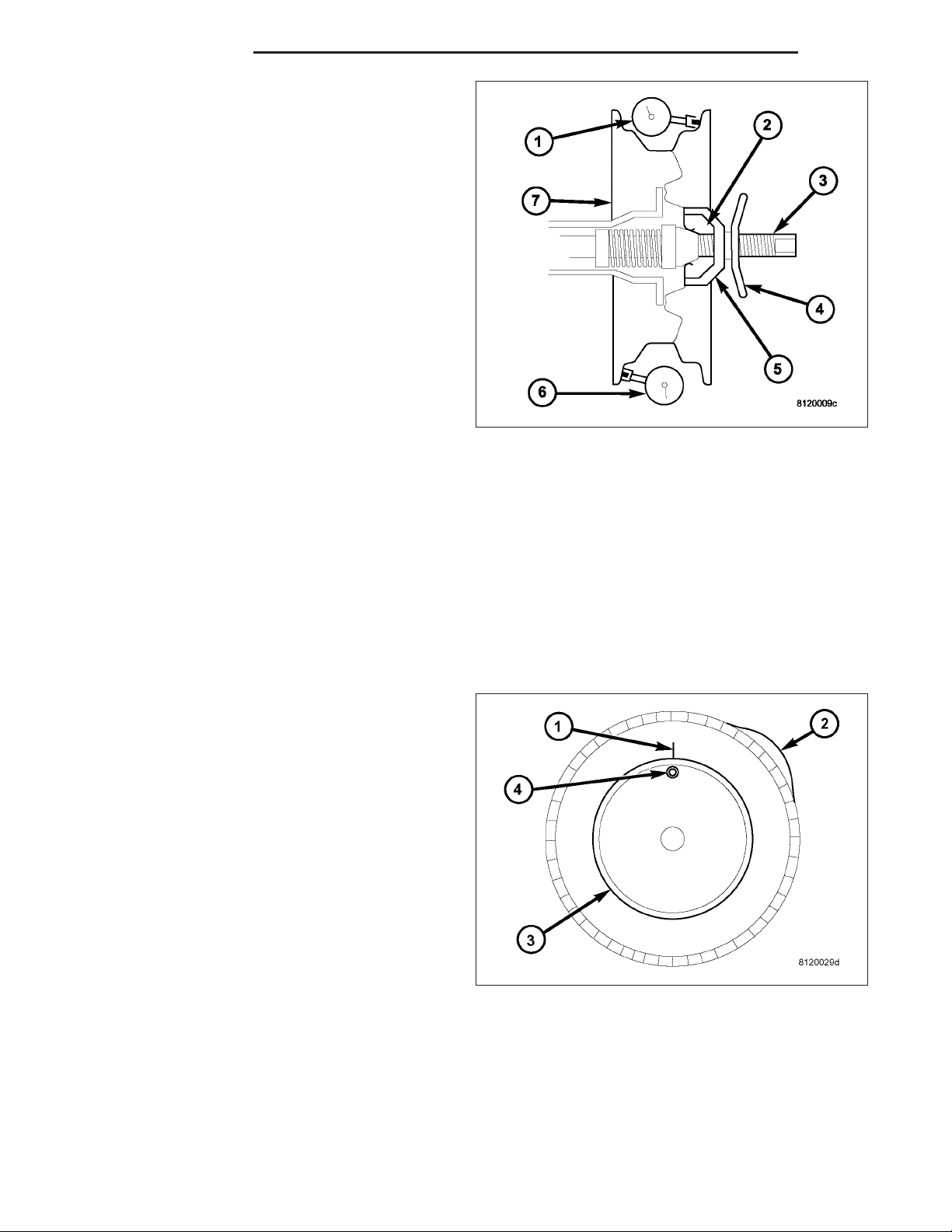
1. Remove the tire and wheel assembly from the
vehicle and mount on a service dynamic balance
machine.
2. Measure the total runout on the center of the tire
tread rib (3) with a dial indicator. Record the indicator reading. Mark the tire to indicate the high
spot (2). Place a mark on the tire at the valve stem
(4) location (1).
DR/DH TIRES/WHEELS 22 - 5
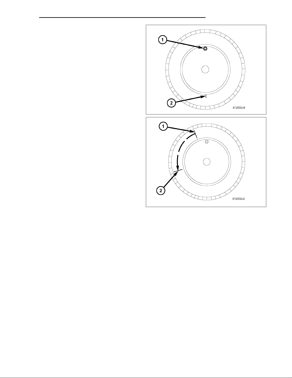
3. Break down the tire and remount it 180 degrees
on the rim (1)(2).
4. Measure the total indicator runout again. Mark the
tire to indicate the high spot.
5. If runout is still excessive, the following procedures
must be done.
• If the high spot is within 101.6 mm (4.0 in.) of the
first spot and is still excessive, replace the tire.
• If the high spot is within 101.6 mm (4.0 in.) of the
first spot on the wheel, the wheel may be out of
specifications. Refer to Wheel and Tire Runout.
• If the high spot is NOT within 101.6 mm (4.0 in.)
of either high spot, draw an arrow on the tread
from second high spot (1) to first (2). Break down
the tire and remount it 90 degrees on rim in that
direction. This procedure will normally reduce the
runout to an acceptable amount, if not replace
the rim.
TIRE AND WHEEL BALANCE
It is recommended that a two plane service dynamic balancer be used when a tire and wheel assembly require
balancing. Refer to balancer operation instructions for proper cone mounting procedures. Typically use front cone
mounting method for steel wheels. For aluminum wheel use back cone mounting method without cone spring.
NOTE: Static should be used only when a two plane balancer is not available.
NOTE: Cast aluminum and forged aluminum wheels require coated balance weights and special alignment
equipment.
Wheel balancing can be accomplished with either on or off vehicle equipment. When using on-vehicle balancing
equipment, remove the opposite wheel/tire. Off-vehicle balancing is recommended.
22 - 6 TIRES/WHEELS DR/DH
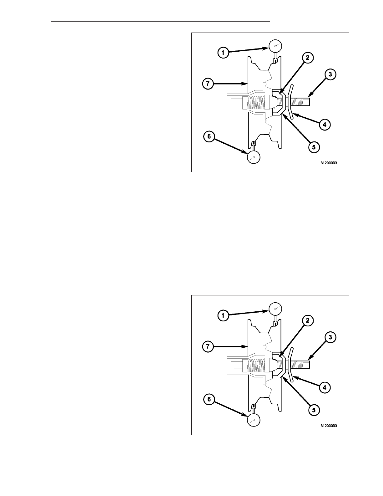
For static balancing, find the location of the heavy
spot (1) causing the imbalance (5). Counter balance
wheel directly opposite the heavy spot. Determine
weight required to counter balance the area of imbalance (4). Place half of this weight on the inner rim
flange (3) and the other half on the outer rim flange
(3).
For dynamic balancing (3), the balancing equipment is
designed to locate the amount of weight to be applied
to both the inner and outer rim flange (2).
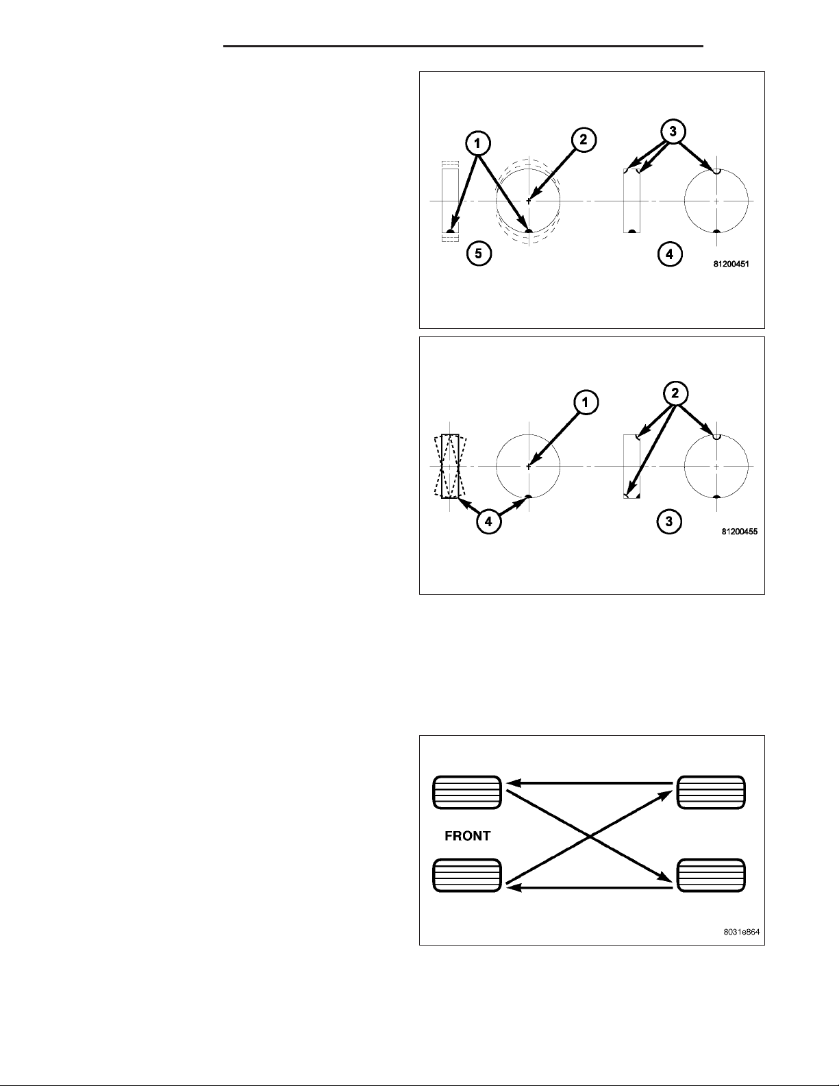
TIRE ROTATION
Tires on the front and rear axles operate at different loads and perform different steering, driving, and braking functions. For these reasons, the tires wear at unequal rates. They may also develop irregular wear patterns. These
effects can be reduced by rotating the tires according to the maintenance schedule in the Owners Manual. This will
improve tread life, traction and maintain a smooth quiet ride.
The recommended method of tire rotation for single
rear wheel is. Other methods can be used, but may
not provide the same tire longevity benefits.