

Page 1

Factory Workshop Manual
Dodge
Stratus
L4-2.4L VIN X (1998)
Anonymous
1st January 2018
Make
Model
Engine and year
This manual was submitted by
Date
Page 2

Dodge Stratus Workshop Manual (L4-2.4L VIN X (1998))
Dodge Workshop Manuals > Relays and Modules > Relays and Modules - Accessories and Optional Equipment > Keyless
Entry Module > Component Information > Adjustments
Page 3

Keyless Entry Module: Adjustments
The scan tool (DRB) and the transmitter must be used to program the Remote Keyless Entry
Module. Refer to the scan tool (DRB) for the procedure.
Page 4

Dodge Stratus Workshop Manual (L4-2.4L VIN X (1998))
Dodge Workshop Manuals > Relays and Modules > Relays and Modules - Body and Frame > Keyless Entry Module >
Component Information > Adjustments
Page 5

Keyless Entry Module: Adjustments
The scan tool (DRB) and the transmitter must be used to program the Remote Keyless Entry
Module. Refer to the scan tool (DRB) for the procedure.
Page 6
Dodge Stratus Workshop Manual (L4-2.4L VIN X (1998))
Dodge Workshop Manuals > Relays and Modules > Relays and Modules - Brakes and Traction Control > ABS Main Relay >
Component Information > Description and Operation
ABS Main Relay: Description and Operation
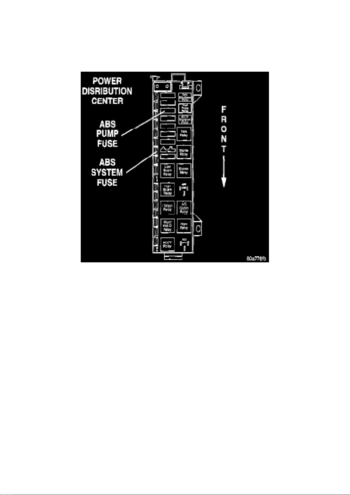
ABS FUSES
Fuse Locations In Power Distribution Center
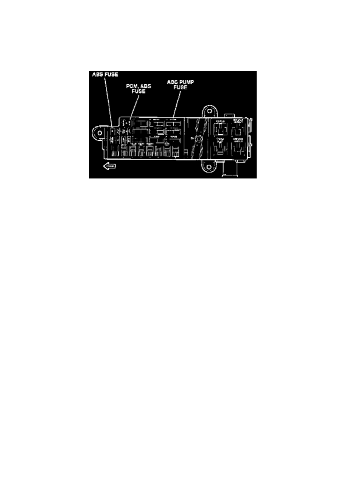
The fuse for the ABS pump motor and the ABS system are located in the Power Distribution Center
(PDC). The PDC is located on the drivers side of the engine compartment forward of the strut
tower.
ABS RELAYS
On the Teves Mark 20 Antilock Brake System both the pump motor relay and the system relay are
located in the CAB. If either of the relays is diagnosed as not functioning properly the CAB will
need to be replaced.
Page 7

Dodge Stratus Workshop Manual (L4-2.4L VIN X (1998))
Dodge Workshop Manuals > Relays and Modules > Relays and Modules - Brakes and Traction Control > Electronic Brake
Control Module > Component Information > Specifications
Page 8

Electronic Brake Control Module: Specifications
Controller Antilock Brakes To HCU Mounting Bolts
............................................................................................................................. 2 Nm (17 inch lbs.)
Page 9
Dodge Stratus Workshop Manual (L4-2.4L VIN X (1998))
Dodge Workshop Manuals > Relays and Modules > Relays and Modules - Brakes and Traction Control > Electronic Brake
Control Module > Component Information > Specifications > Page 18
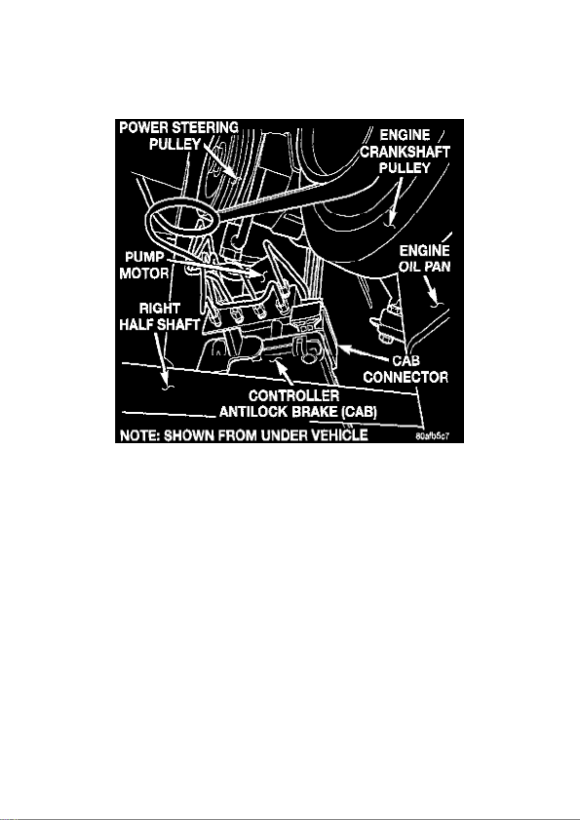
Electronic Brake Control Module: Locations
ICU Mounting Location
Mounted on the crossmember over the steering gear on the right side.
Page 10
Dodge Stratus Workshop Manual (L4-2.4L VIN X (1998))
Dodge Workshop Manuals > Relays and Modules > Relays and Modules - Brakes and Traction Control > Electronic Brake
Control Module > Component Information > Specifications > Page 19
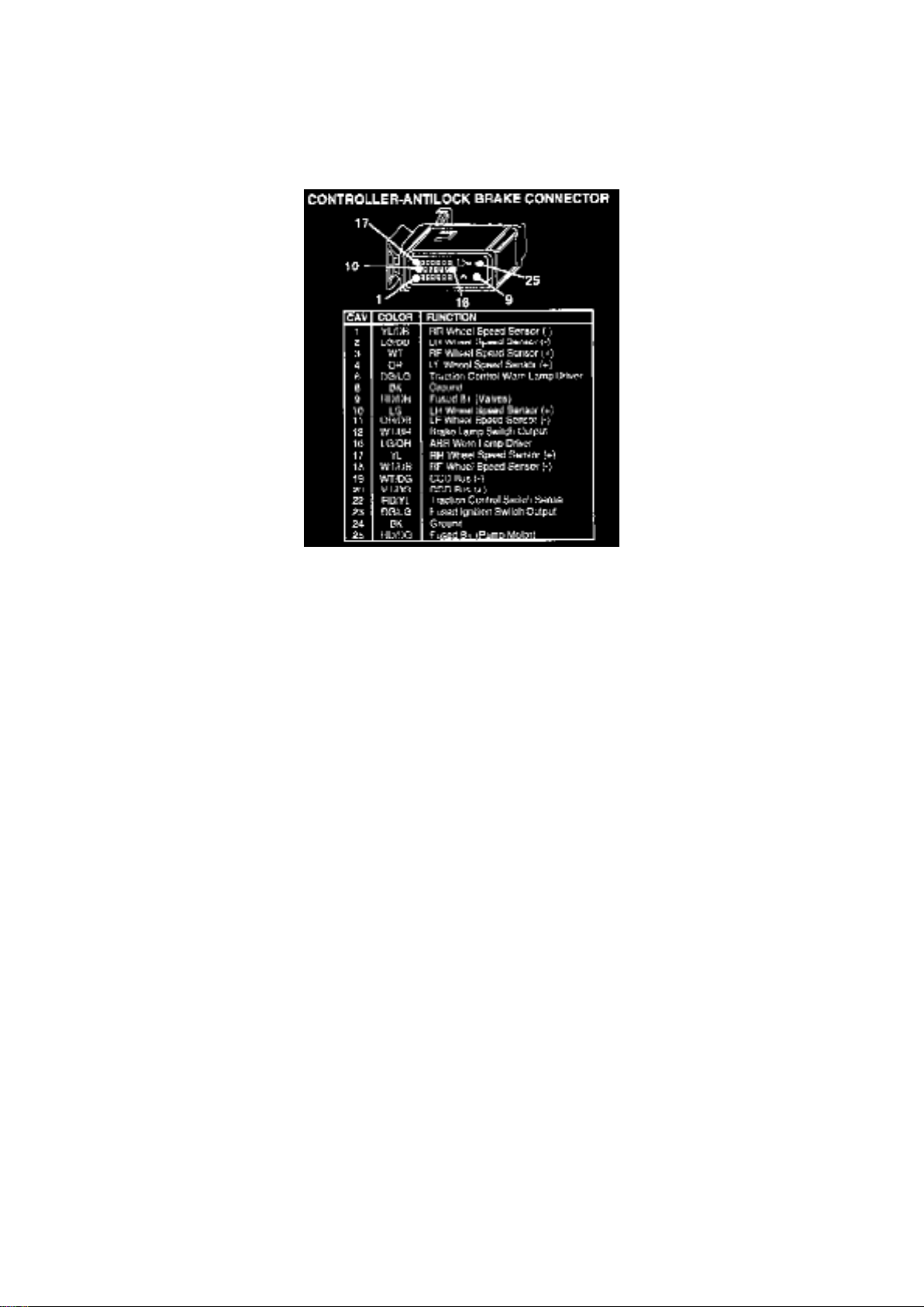
Controller Antilock Brakes Connector
Page 11

Dodge Stratus Workshop Manual (L4-2.4L VIN X (1998))
Dodge Workshop Manuals > Relays and Modules > Relays and Modules - Brakes and Traction Control > Electronic Brake
Control Module > Component Information > Specifications > Page 20
Page 12

Electronic Brake Control Module: Description and Operation
The Controller Antilock Brake (CAB) is a microprocessor-based device that monitors wheel speeds
and controls the antilock functions. The CAB contains two microprocessors that receive identical
sensor signals and then independently process the information. The results are then compared to
make sure that they agree. Otherwise, the CAB will turn off the antilock and turn on the Antilock
Brake System (ABS) amber warning lamp.
The primary functions of the CAB are to:
- detect wheel locking tendencies
- control fluid pressure modulation to the brakes during antilock stop
- monitor the system for proper operation
- provide communication to the DRB while in diagnostic mode
- store diagnostic information in non-volatile memory
The CAB continuously monitors the speed of each wheel. When a wheel locking tendency is
detected, the CAB will command the appropriate valve to modulate brake fluid pressure in its
hydraulic unit. Brake pedal position is maintained during an antilock stop by being a closed system
with the use of 2 accumulators. The CAB continues to control pressure in individual hydraulic
circuits until a wheel locking tendency is no longer present. The CAB turns on the pump motor
during an antilock stop.
The antilock brake system is constantly monitored by the CAB for proper operation If the CAB
detects a system malfunction, it can disable the antilock system and turn on the ABS warning lamp.
If the antilock function is disabled, the system will revert to standard base brake system operation.
CAB Inputs Include The Following:
- ABS Warning Lamp
- Diagnostic Communication
- Four Wheel Speed Sensors
- Ignition Switch
- Fused B+
- Stop Lamp Switch
CAB Outputs Include The Following:
- ABS Warning Light Actuation
- Voltage
- Eight Valves
- Diagnostic Communication
- Body Controller Communication
Page 13
Dodge Stratus Workshop Manual (L4-2.4L VIN X (1998))
Dodge Workshop Manuals > Relays and Modules > Relays and Modules - Brakes and Traction Control > Electronic Brake
Control Module > Component Information > Specifications > Page 21
Page 14

Electronic Brake Control Module: Service and Repair
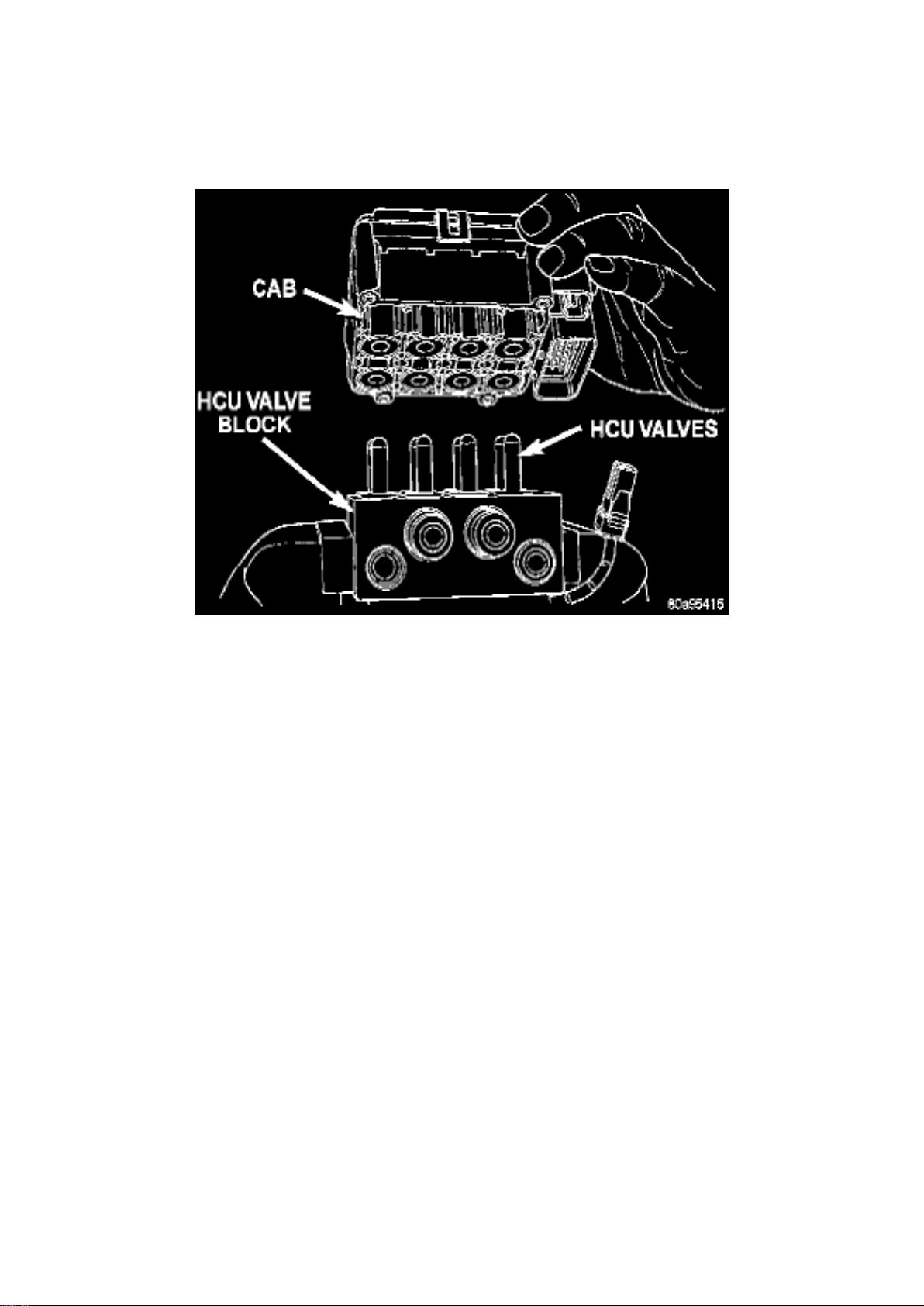
REMOVE
NOTE: To replace the Controller Antilock Brakes (CAB) on this vehicle, the Integrated Control Unit
(ICU) and CAB need to be removed from the vehicle as a unit. The CAB can then be separated
from the Hydraulic Control Unit (HCU). Do not attempt to replace the CAB with the ICU mounted in
the vehicle.
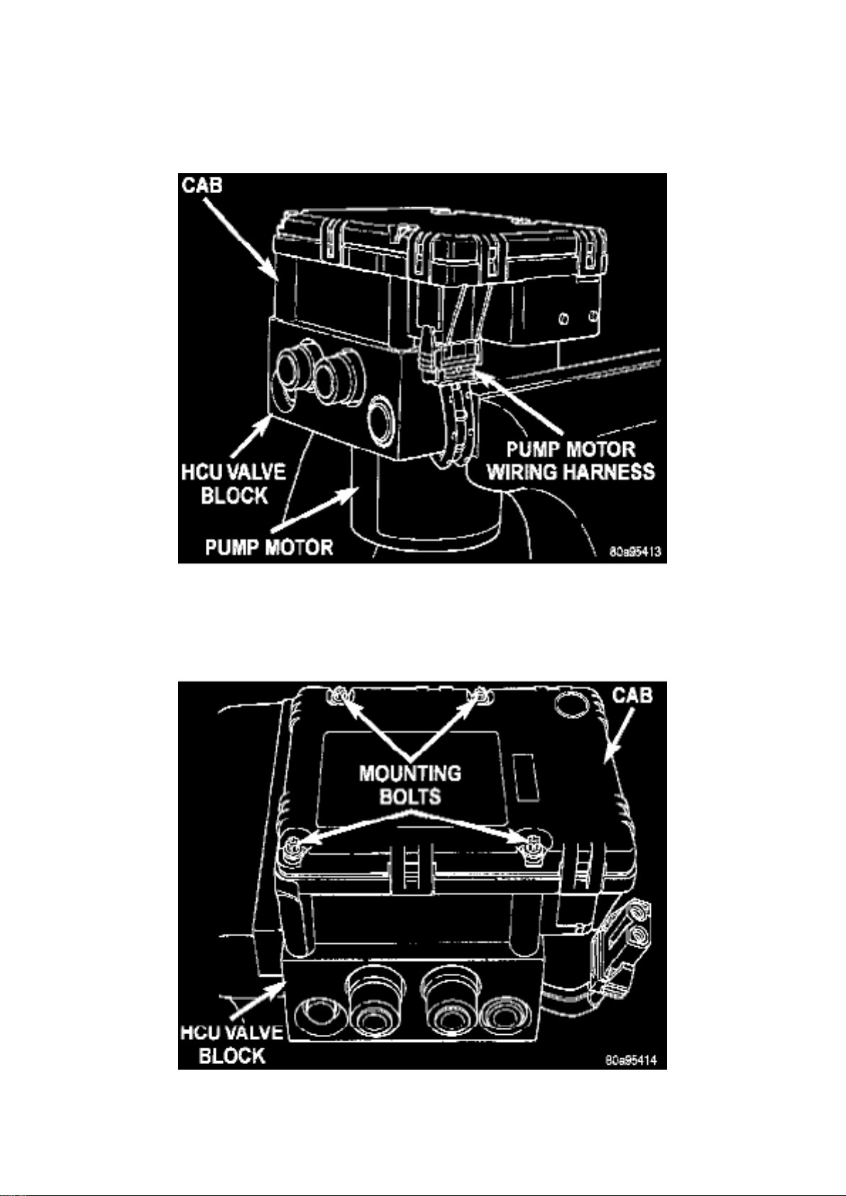
1. Remove the ICU from the vehicle.
Pump Motor To CAB Wiring Harness
2. Unplug the pump motor wiring harness from the CAB.
CAB Attaching Bolts
3. Remove the 4 bolts attaching the CAB to the HCU.
Page 15
Dodge Stratus Workshop Manual (L4-2.4L VIN X (1998))
Dodge Workshop Manuals > Relays and Modules > Relays and Modules - Brakes and Traction Control > Electronic Brake
Control Module > Component Information > Specifications > Page 22
Remove/Install CAB
4. Remove the CAB from the HCU.
INSTALL
1. Install the CAB on the HCU. 2. Install the 4 bolts mounting the CAB to the HCU. Tighten the CAB
mounting bolts to a torque of 2 Nm (17 inch lbs.). 3. Plug the pump/motor wiring harness into the
CAB. 4. Install the ICU. 5. Bleed the base brakes and the ABS brakes hydraulic system. 6. Road
test vehicle to ensure proper operation of the base and ABS brake systems.
Page 16

Dodge Stratus Workshop Manual (L4-2.4L VIN X (1998))
Dodge Workshop Manuals > Relays and Modules > Relays and Modules - Cooling System > Radiator Cooling Fan Control
Module Relay > Component Information > Technical Service Bulletins > Cooling System - Manual Revisions
Page 17

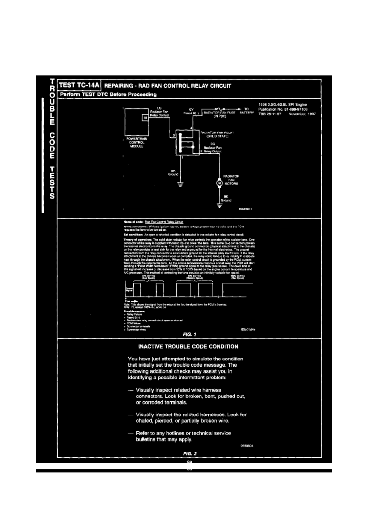
Radiator Cooling Fan Control Module Relay: Technical Service Bulletins Cooling System - Manual
Revisions
NUMBER: 26-11-97G
GROUP: Miscellaneous
DATE: November, 1997
REVISIONS ARE HIGHLIGHTED WITH BLACK BARS IN THE MARGIN
Models: 1998 2.0L/2.4L/2.5L SFI Engine Diagnostic Manual - Publication Number 81-699-97108
DESCRIPTION OF CHANGES
Revisions to the radiator fan control relay test
Page 18
Dodge Stratus Workshop Manual (L4-2.4L VIN X (1998))
Dodge Workshop Manuals > Relays and Modules > Relays and Modules - Cooling System > Radiator Cooling Fan Control
Module Relay > Component Information > Technical Service Bulletins > Cooling System - Manual Revisions > Page 28
Page 19

98
Page 20
Dodge Stratus Workshop Manual (L4-2.4L VIN X (1998))
Dodge Workshop Manuals > Relays and Modules > Relays and Modules - Cooling System > Radiator Cooling Fan Motor
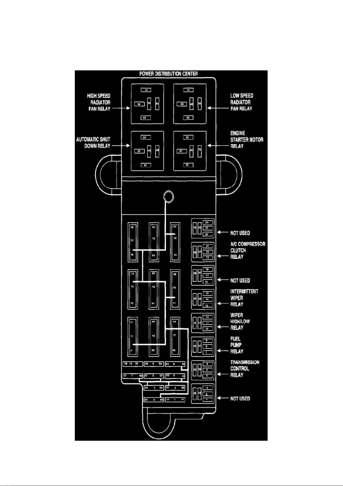
Relay > Component Information > Locations > High Speed Fan Relay
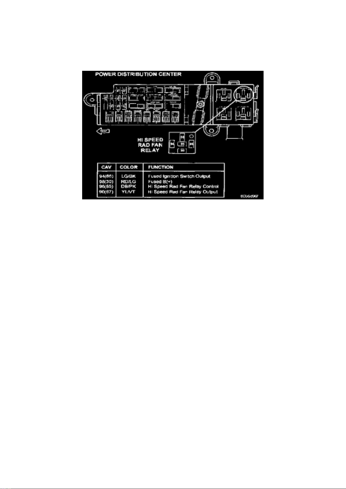
Power Distribution Center, Hi Speed Rad Fan Relay
Page 21
Dodge Stratus Workshop Manual (L4-2.4L VIN X (1998))
Dodge Workshop Manuals > Relays and Modules > Relays and Modules - Cooling System > Radiator Cooling Fan Motor
Relay > Component Information > Locations > High Speed Fan Relay > Page 33
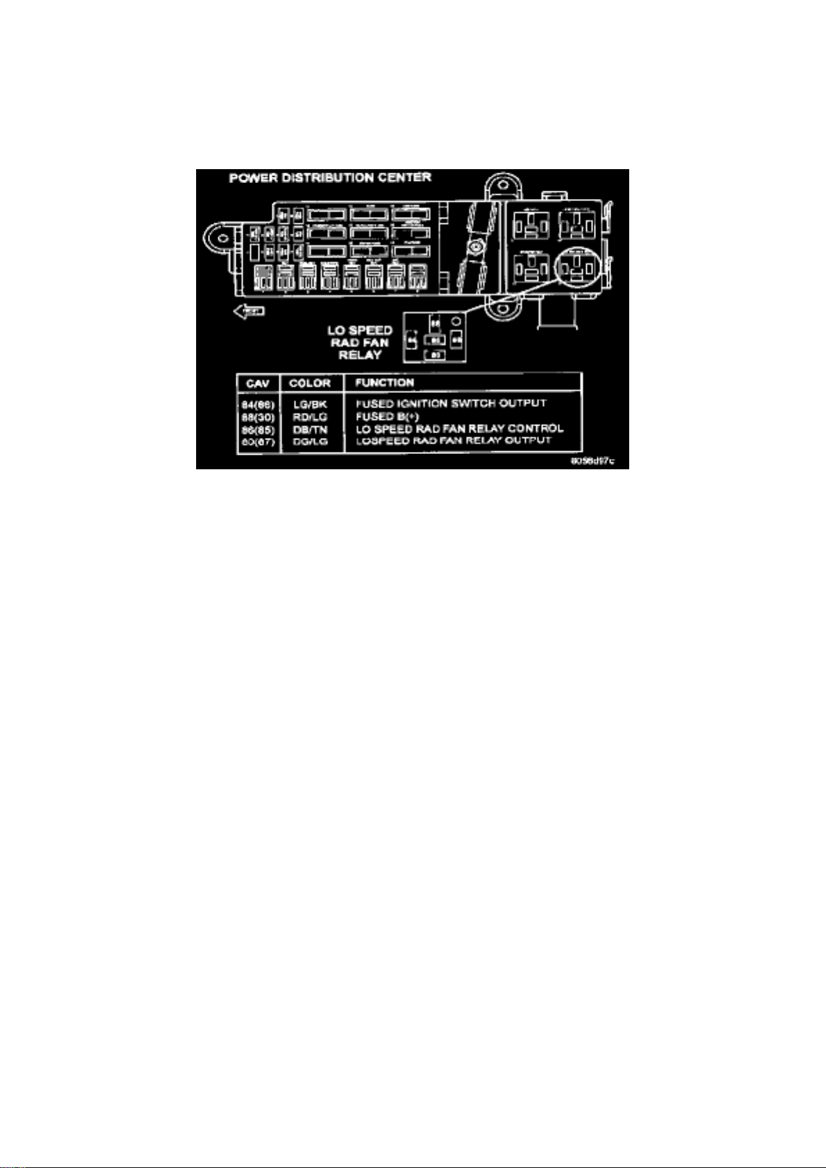
Power Distribution Center, Lo Speed Radiator Fan
Page 22
Dodge Stratus Workshop Manual (L4-2.4L VIN X (1998))
Dodge Workshop Manuals > Relays and Modules > Relays and Modules - Cooling System > Radiator Cooling Fan Motor
Relay > Component Information > Locations > High Speed Fan Relay > Page 34
Page 23

Power Distribution
Page 24
Dodge Stratus Workshop Manual (L4-2.4L VIN X (1998))
Dodge Workshop Manuals > Relays and Modules > Relays and Modules - Cooling System > Radiator Cooling Fan Motor
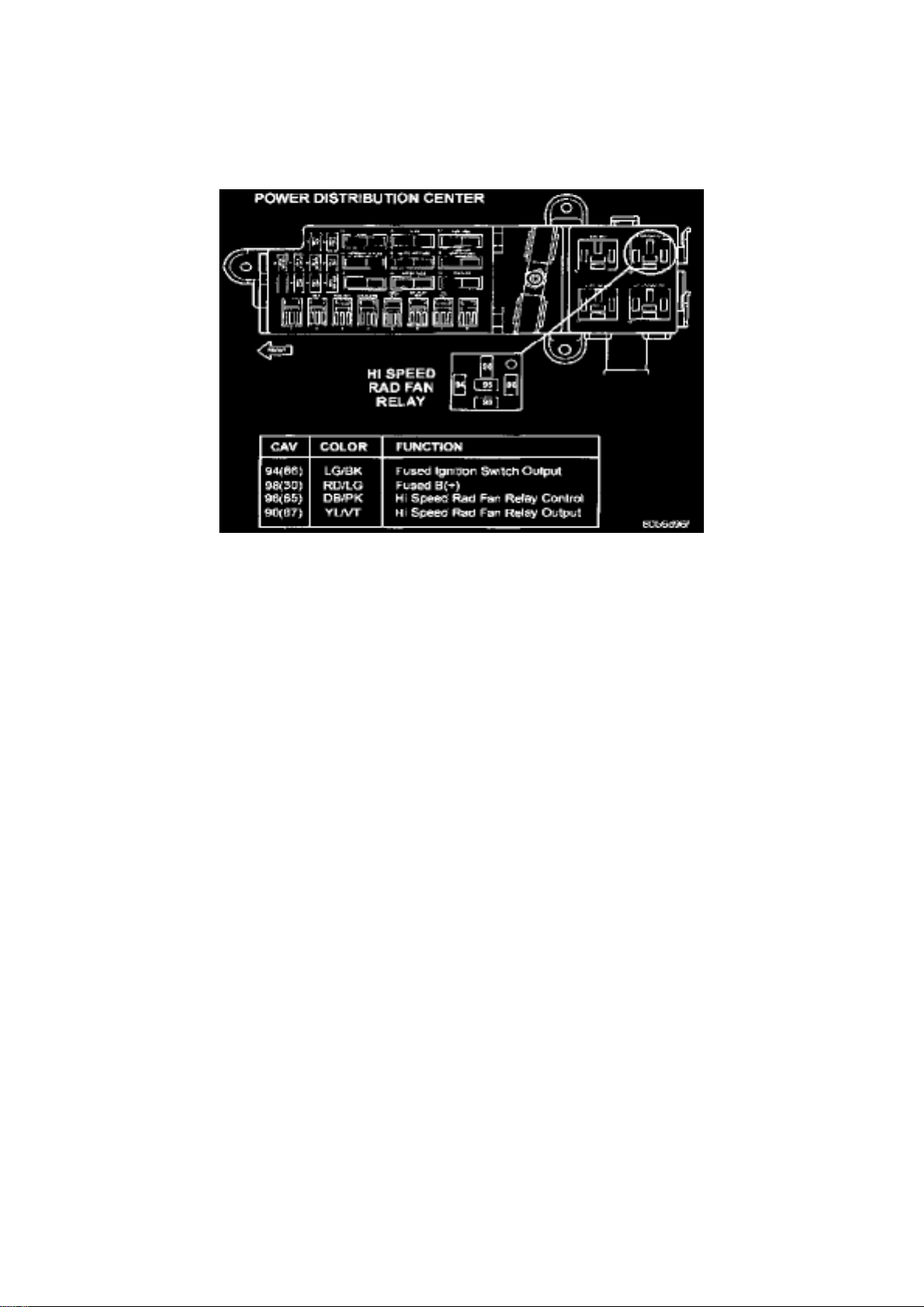
Relay > Component Information > Diagrams > High Speed Radiator Fan Relay
Power Distribution Center, Hi Speed Rad Fan Relay
Page 25
Dodge Stratus Workshop Manual (L4-2.4L VIN X (1998))
Dodge Workshop Manuals > Relays and Modules > Relays and Modules - Cooling System > Radiator Cooling Fan Motor
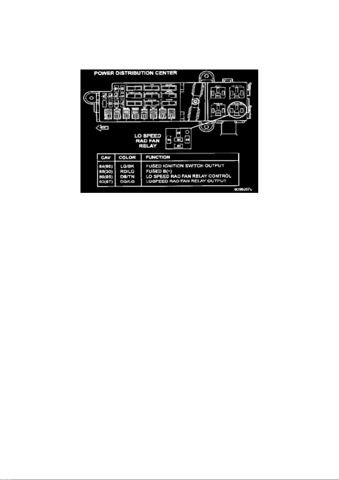
Relay > Component Information > Diagrams > High Speed Radiator Fan Relay > Page 37
Power Distribution Center, Lo Speed Radiator Fan
Page 26
Dodge Stratus Workshop Manual (L4-2.4L VIN X (1998))
Dodge Workshop Manuals > Relays and Modules > Relays and Modules - HVAC > Compressor Clutch Relay > Component
Information > Locations > Component Locations
Page 27

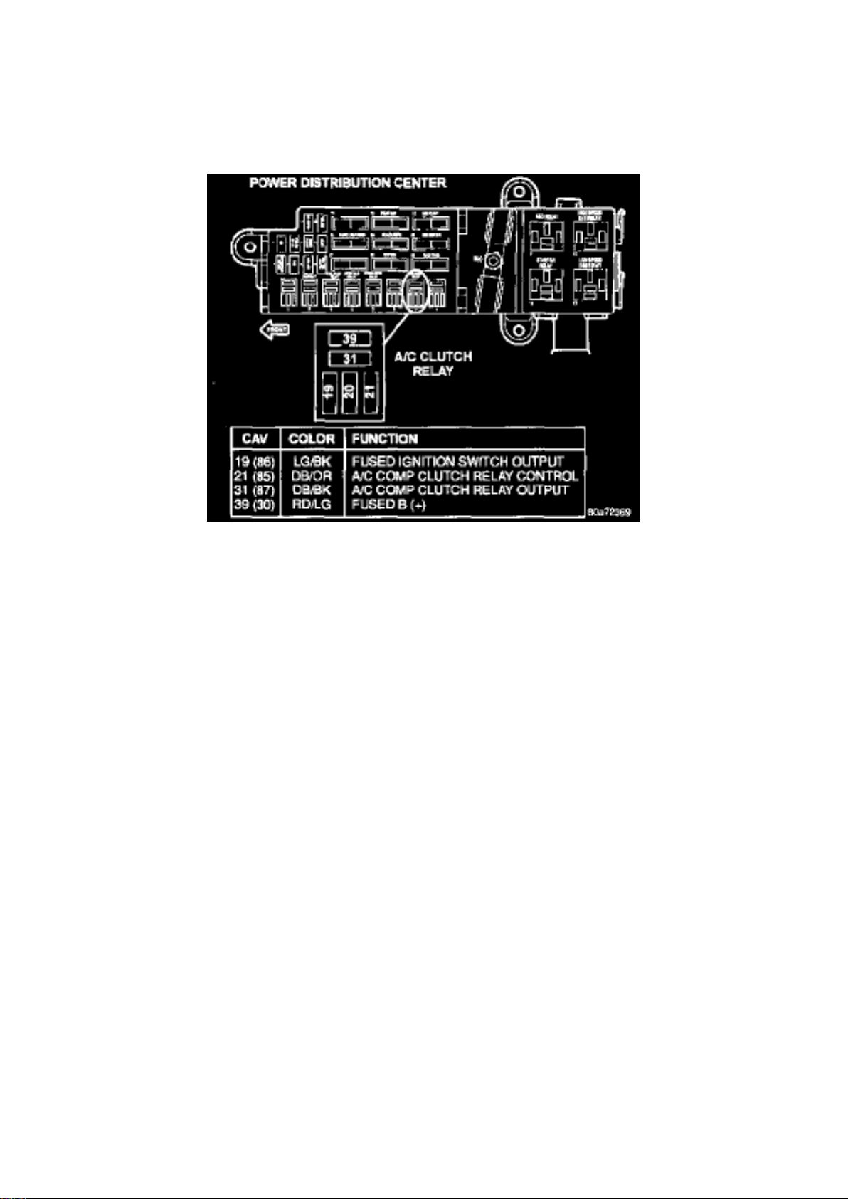
Compressor Clutch Relay: Component Locations
Power Distribution
Page 28
Dodge Stratus Workshop Manual (L4-2.4L VIN X (1998))
Dodge Workshop Manuals > Relays and Modules > Relays and Modules - HVAC > Compressor Clutch Relay > Component
Information > Locations > Component Locations > Page 43
Power Distribution Center, A/C Clutch Relay
Page 29
Dodge Stratus Workshop Manual (L4-2.4L VIN X (1998))
Dodge Workshop Manuals > Relays and Modules > Relays and Modules - HVAC > Compressor Clutch Relay > Component
Information > Locations > Component Locations > Page 44
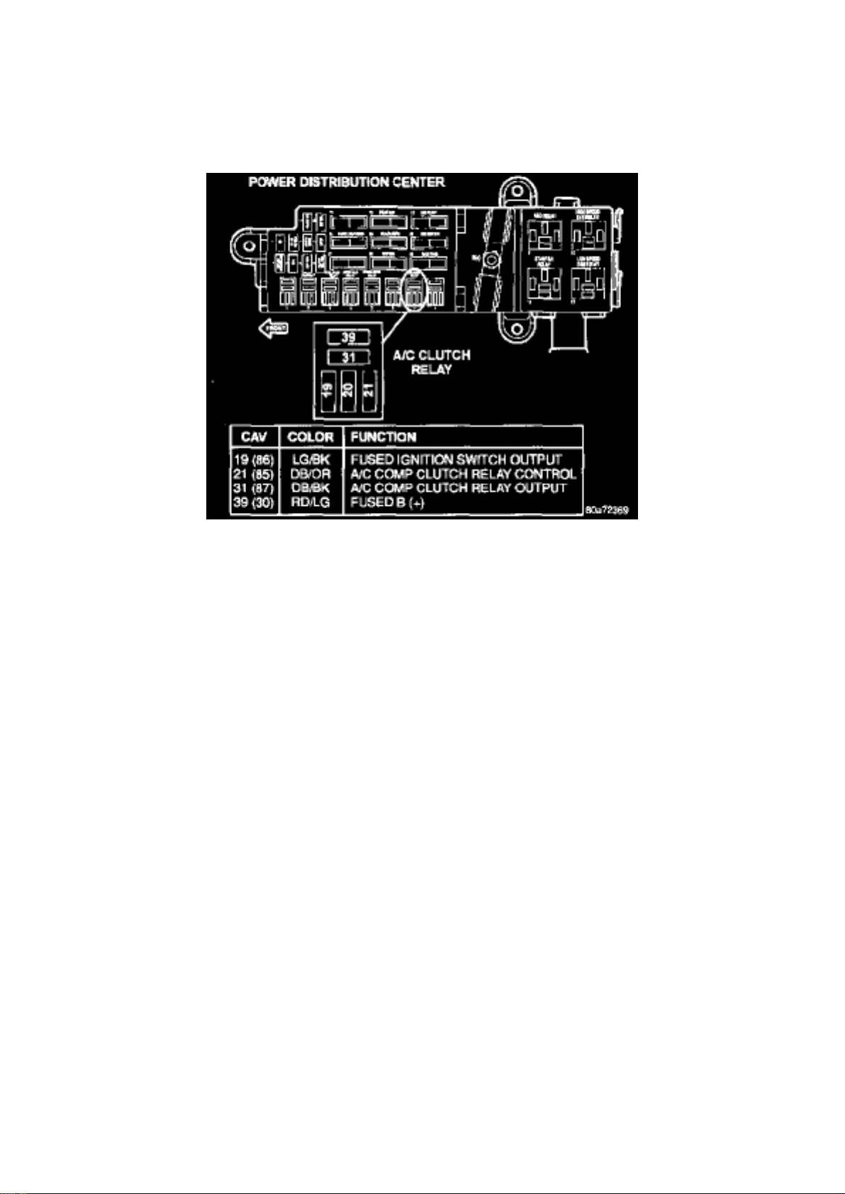
Power Distribution Center, A/C Clutch Relay
Page 30
Dodge Stratus Workshop Manual (L4-2.4L VIN X (1998))
Dodge Workshop Manuals > Relays and Modules > Relays and Modules - HVAC > Control Module HVAC > Component
Information > Service and Repair
Page 31

Control Module HVAC: Service and Repair
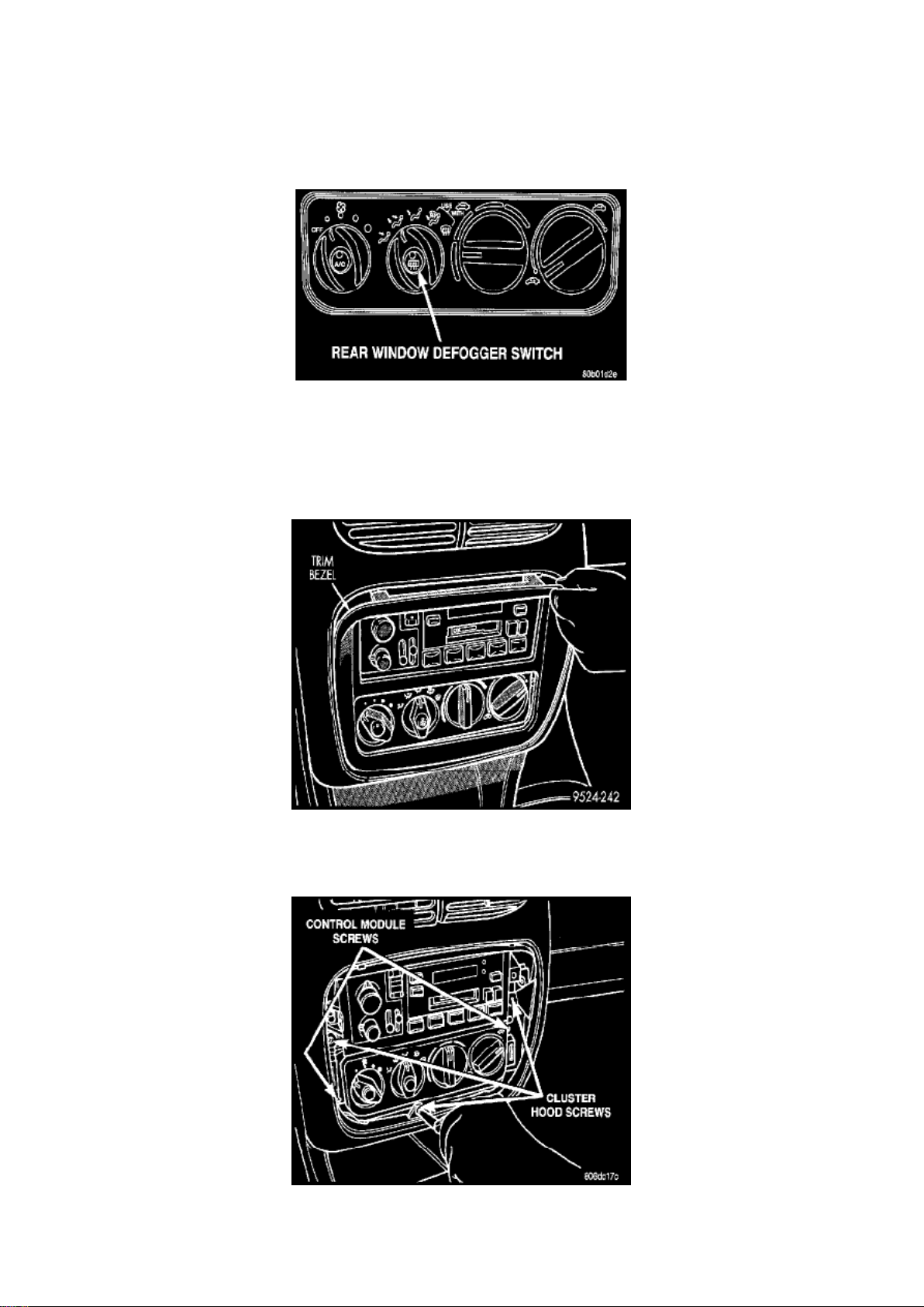
HVAC Control Module
The control module is located below the radio.
REMOVAL 1. Place the ignition key in the OFF position before removing control module.
Control Module
2. Remove trim bezel.
Control Module Screws
3. Remove cluster hood bezel retaining screws in the trim bezel opening. 4. Pry up the cluster hood
bezel a few inches to expose the cubby bin/cigar lighter bezel screws. 5. Remove the cubby
bin/cigar lighter bezel and wiring.
Page 32
Dodge Stratus Workshop Manual (L4-2.4L VIN X (1998))
Dodge Workshop Manuals > Relays and Modules > Relays and Modules - HVAC > Control Module HVAC > Component
Information > Service and Repair > Page 48
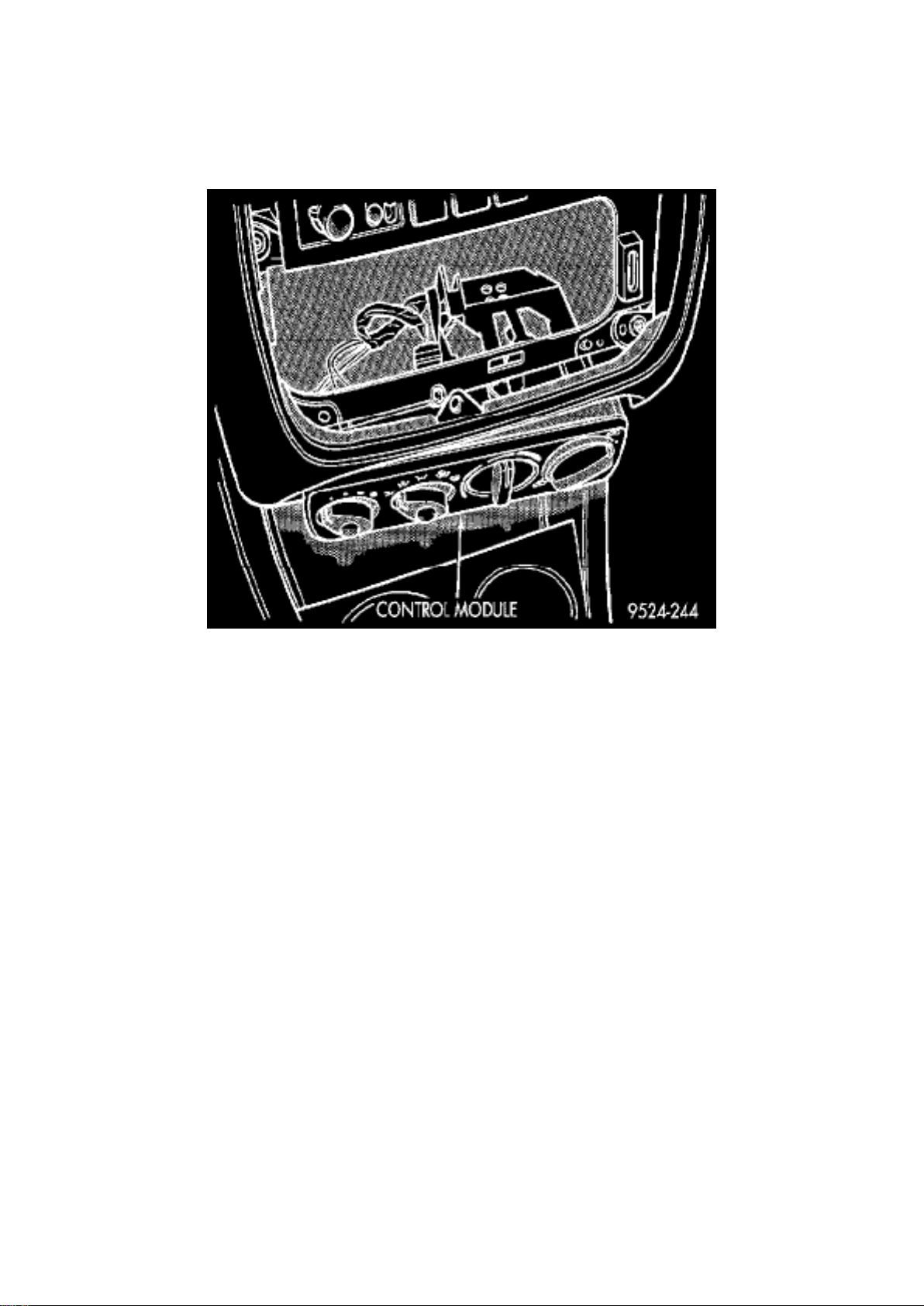
6. Remove the control module retaining screws.
Control Module At Bezel Opening
7. Drop the A/C control module into the cigar lighter/cubby bin bezel opening. Then disconnect the
wiring on the rear of the control module. 8. Release the cable clips from the top of the control
module. Retain the clips for future use. Then disconnect the temperature control and
recirculation control cables.
9. Remove the control module.
INSTALLATION For installation, reverse the above procedures. Verify that the cables are properly adjusted and the
module is seated properly.
Cable Adjustment The cables must be adjusted for proper function of the control module. To adjust
the cable, attach the cable to the lever arm of the control module. 'Turn the knob fully
counterclockwise. Pull the cable jacket away from the cable end until taut. Clip the cable jacket to
the control module. The knob should travel a full 1800 if the cable is properly adjusted.
Page 33
Dodge Stratus Workshop Manual (L4-2.4L VIN X (1998))
Dodge Workshop Manuals > Relays and Modules > Relays and Modules - Lighting and Horns > Battery Discharge
Protection Relay, Lighting > Component Information > Locations
Page 34

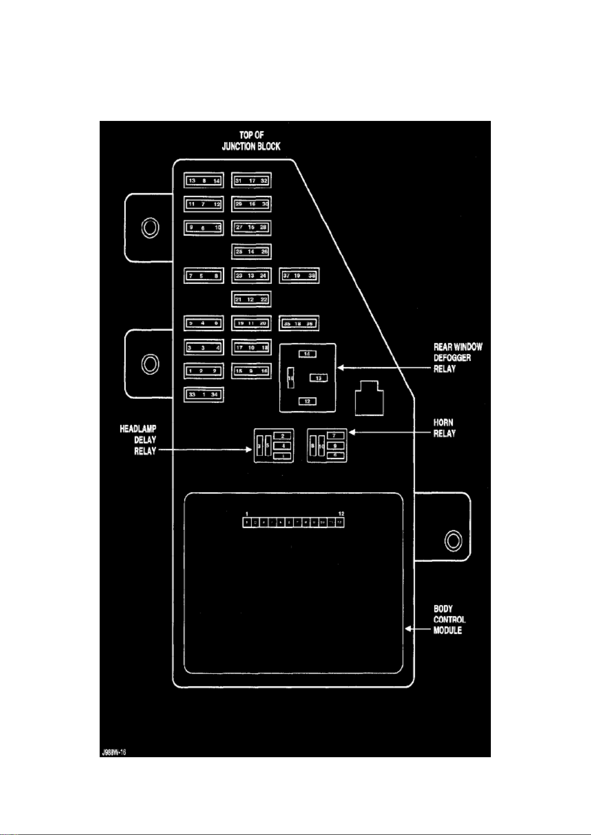
Junction Block
Page 35

Dodge Stratus Workshop Manual (L4-2.4L VIN X (1998))
Dodge Workshop Manuals > Relays and Modules > Relays and Modules - Lighting and Horns > Battery Discharge
Protection Relay, Lighting > Component Information > Locations > Page 53
Page 36

Battery Discharge Protection Relay: Description and Operation
SYSTEM OPERATION
The optional Headlamp Time Delay system is controlled by the Body Controller (BC) and a relay
located in the junction block. The headlamp time delay system can be activated by turning ON the
headlamps when the engine is running, turn OFF the ignition switch, then turn OFF the headlamp
switch. The BC will allow the headlamps to remain ON for 90 Seconds before they automatically
turn off.
Page 37
Dodge Stratus Workshop Manual (L4-2.4L VIN X (1998))
Dodge Workshop Manuals > Relays and Modules > Relays and Modules - Lighting and Horns > Headlamp Control Module
> Component Information > Service and Repair
Headlamp Control Module: Service and Repair
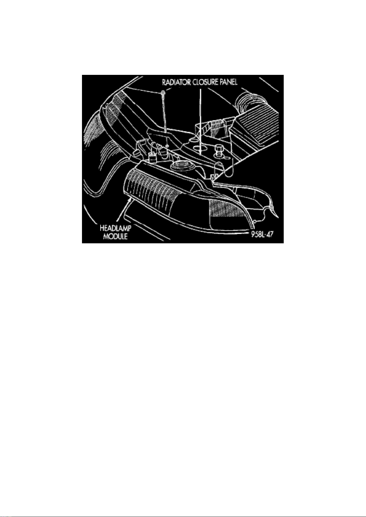
The headlamp module contains the park and turn signal lamps and is serviced as an assembly.
REMOVAL 1. Release hood latch and open hood.
Headlamp Module
2. Remove screws holding headlamp module to radiator closure panel. 3. Separate headlamp
module from radiator closure panel. 4. Disengage wire connector from back of headlamp bulb. 5.
Rotate Park lamp socket counterclockwise one quarter turn. 6. Pull socket from back of lamp. 7.
Separate headlamp module from vehicle.
INSTALLATION Reverse the preceding operation.
Page 38

Dodge Stratus Workshop Manual (L4-2.4L VIN X (1998))
Dodge Workshop Manuals > Relays and Modules > Relays and Modules - Lighting and Horns > Headlamp Relay >
Component Information > Testing and Inspection
Page 39

Headlamp Relay: Testing and Inspection
For test of headlamp relay use a known good relay.
Page 40
Dodge Stratus Workshop Manual (L4-2.4L VIN X (1998))
Dodge Workshop Manuals > Relays and Modules > Relays and Modules - Lighting and Horns > Horn Relay > Component
Information > Locations
Page 41

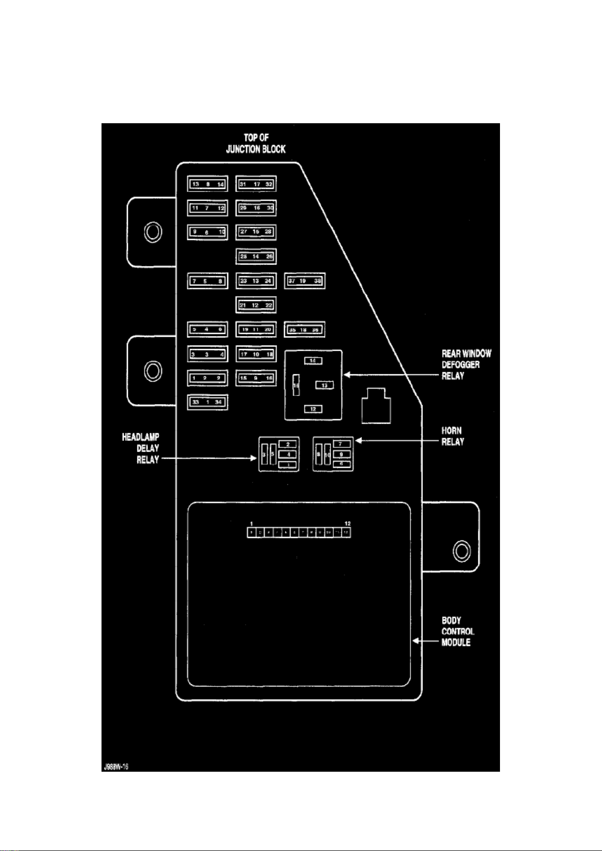
Junction Block
Page 42

Dodge Stratus Workshop Manual (L4-2.4L VIN X (1998))
Dodge Workshop Manuals > Relays and Modules > Relays and Modules - Lighting and Horns > Horn Relay > Component
Information > Locations > Page 63
Page 43

Horn Relay: Description and Operation
SYSTEM OPERATION
The horn relay is a International Standards Organization (ISO) micro-relay. The terminal
designations and functions are the same as a conventional ISO relay. However, the micro-relay
terminal orientation (or footprint) is different, current capacity is lower, and the relay case
dimensions are smaller than on the conventional ISO relay
The horn relay is a electromechanical device that switches current to the horn when the Driver
Airbag Module is depressed. See the Diagnosis and Testing for more information on the operation
of the horn relay.
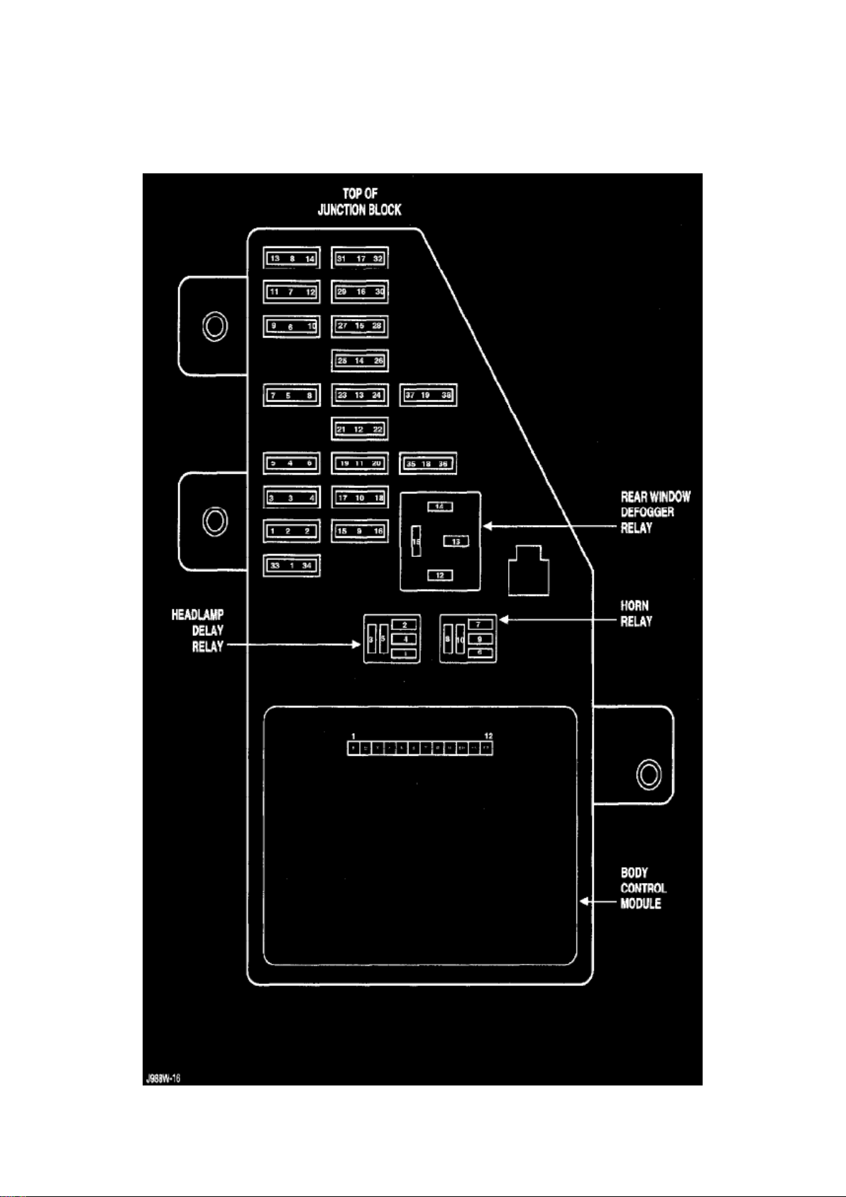
The horn relay is located in the Junction Block. Refer to the Junction Block label for horn relay
identification and location.
If a problem is encountered with a continuously sounding horn, it can usually be quickly resolved by
removing the horn relay from the Junction Block until further diagnosis is completed. The horn relay
cannot be repaired and, if faulty, it must be replaced.
Page 44
Dodge Stratus Workshop Manual (L4-2.4L VIN X (1998))
Dodge Workshop Manuals > Relays and Modules > Relays and Modules - Lighting and Horns > Horn Relay > Component
Information > Locations > Page 64
Horn Relay: Testing and Inspection
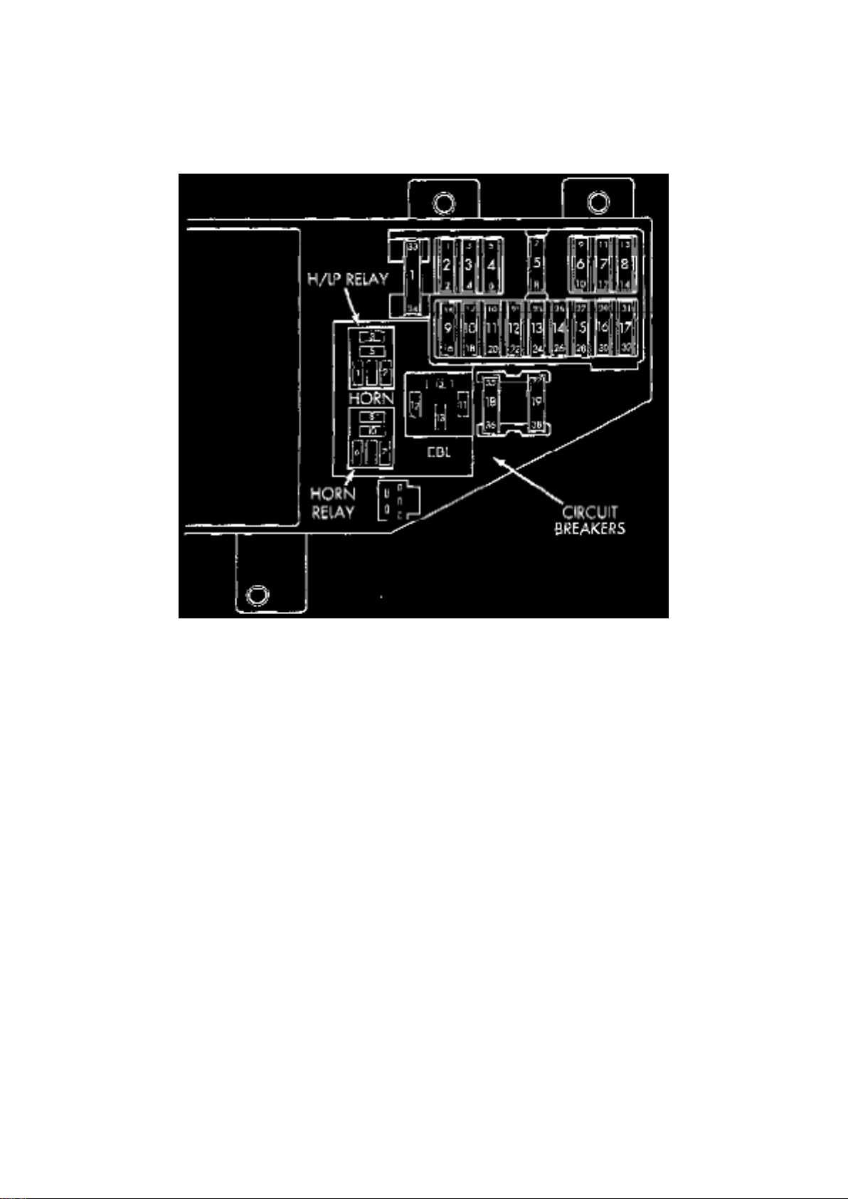
Horn Relay Location
1. Remove horn relay from the Junction Block. 2. Using ohmmeter, test between the Junction Block
relay terminal 7 and ground for continuity.
a. When the horn contact is not depressed, no continuity. b. Continuity to ground when horn
contact is depressed. c. If continuity is not correct, repair horn contact or wiring as necessary.
3. Insert a jumper wire between terminals 8 and 10 of the horn relay in the Junction Block.
a. If horns sound replace relay. b. If the horns do not sound, install horn relay and refer to Horn
Test.
4. Using voltmeter, test battery voltage:
a. Test Junction Block horn relay terminals 6 and 8 for voltage from fuse 8. b. If not OK, repair as
necessary.
Page 45
Dodge Stratus Workshop Manual (L4-2.4L VIN X (1998))
Dodge Workshop Manuals > Relays and Modules > Relays and Modules - Lighting and Horns > Horn Relay > Component
Information > Locations > Page 65
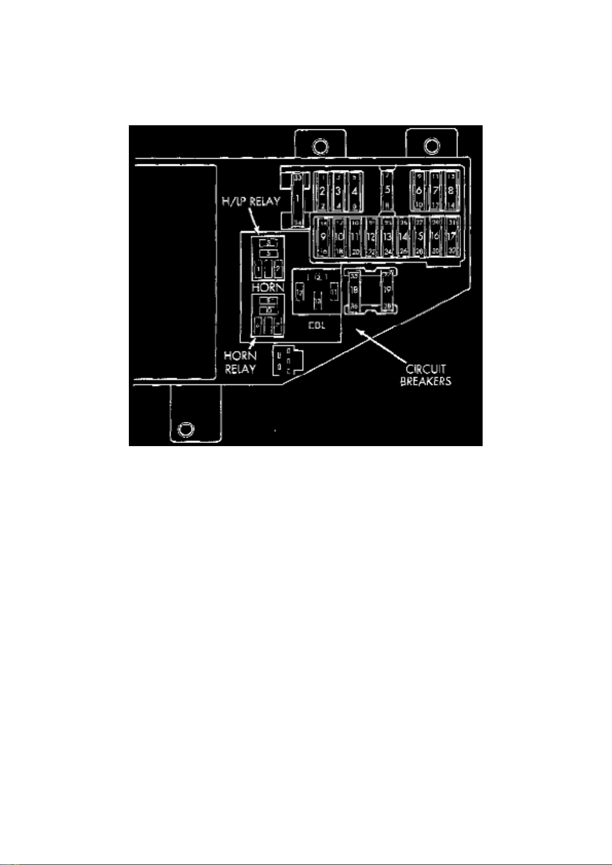
Horn Relay: Service and Repair
REMOVAL
1. Open driver's door and remove instrument panel end cover.
Horn Relay Location
2. Remove horn relay.
INSTALLATION
- For installation, reverse the above procedures.
Page 46
Dodge Stratus Workshop Manual (L4-2.4L VIN X (1998))
Dodge Workshop Manuals > Relays and Modules > Relays and Modules - Power and Ground Distribution > Relay Box >
Component Information > Locations
ABS Fuses
Page 47
Dodge Stratus Workshop Manual (L4-2.4L VIN X (1998))
Dodge Workshop Manuals > Relays and Modules > Relays and Modules - Power and Ground Distribution > Relay Box >
Component Information > Diagrams > Junction Block
Page 48

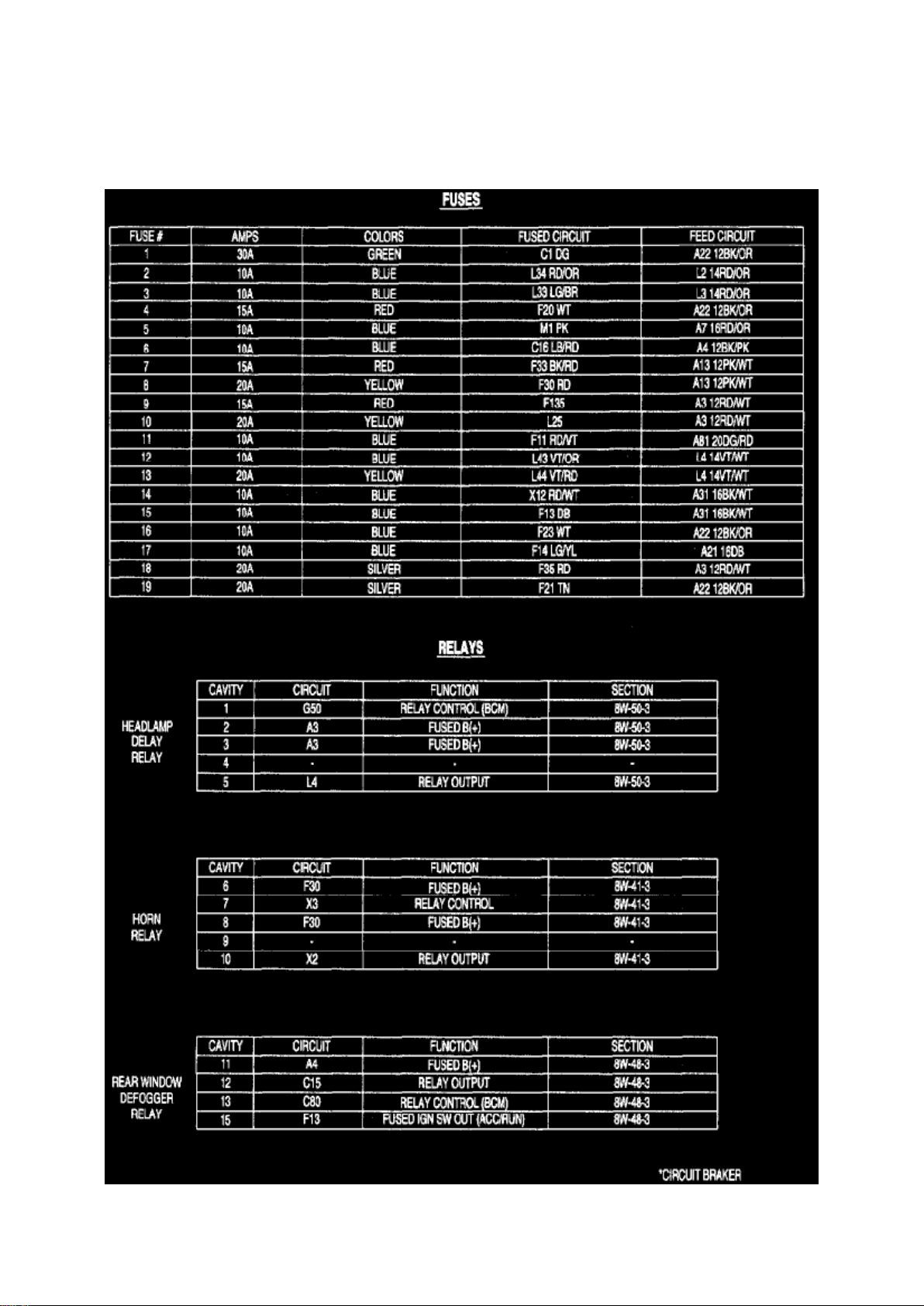
Relay Box: Diagrams Junction Block
Junction Block
Page 49
Dodge Stratus Workshop Manual (L4-2.4L VIN X (1998))
Dodge Workshop Manuals > Relays and Modules > Relays and Modules - Power and Ground Distribution > Relay Box >
Component Information > Diagrams > Junction Block > Page 72
Page 50

Junction Block
Page 51
Dodge Stratus Workshop Manual (L4-2.4L VIN X (1998))
Dodge Workshop Manuals > Relays and Modules > Relays and Modules - Power and Ground Distribution > Relay Box >
Component Information > Diagrams > Junction Block > Page 73
Page 52

Junction Block
Page 53
Dodge Stratus Workshop Manual (L4-2.4L VIN X (1998))
Dodge Workshop Manuals > Relays and Modules > Relays and Modules - Power and Ground Distribution > Relay Box >
Component Information > Diagrams > Junction Block > Page 74
Page 54

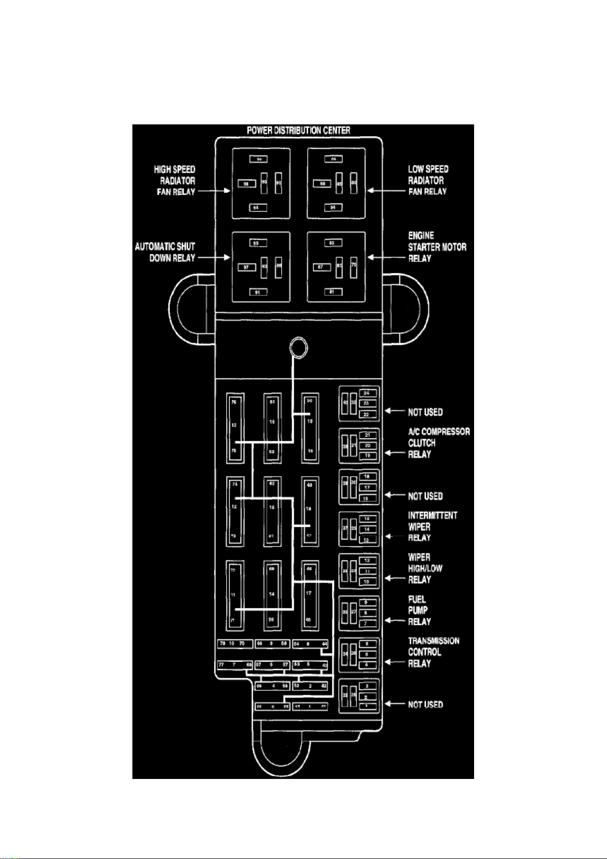
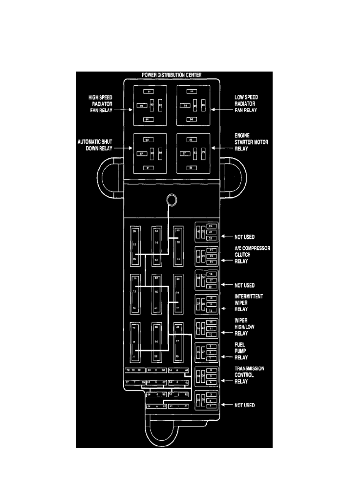
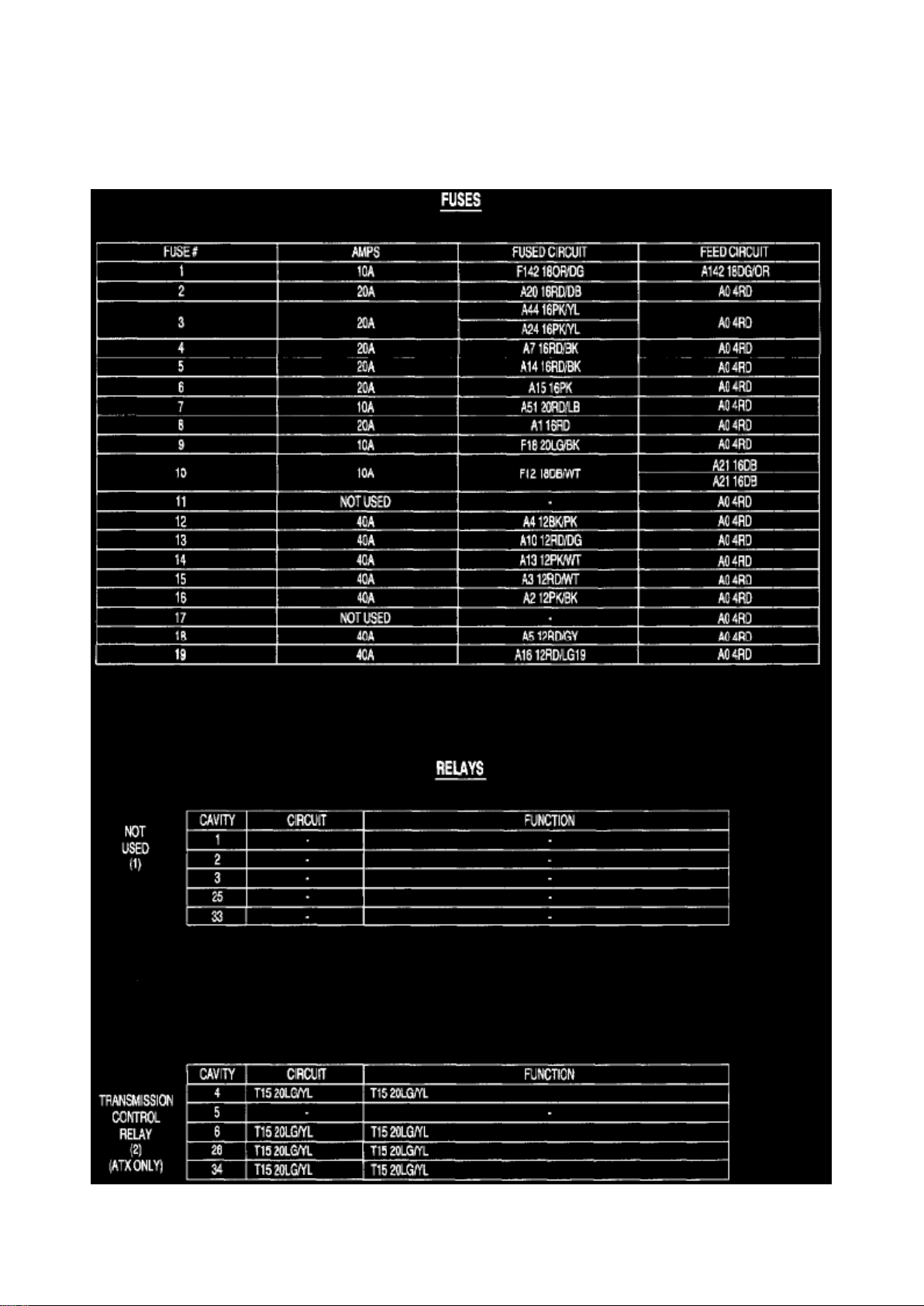
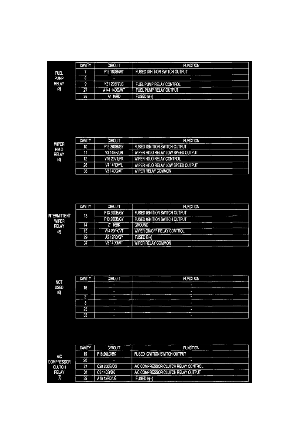
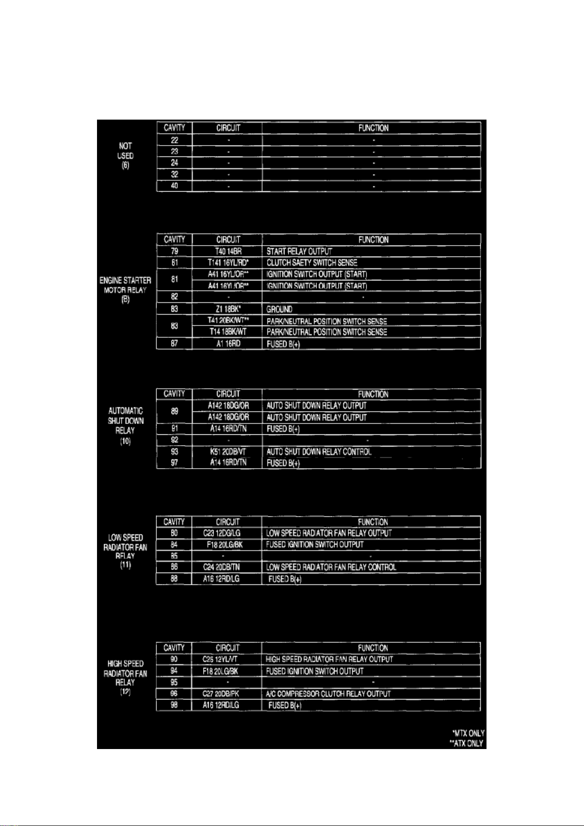
Relay Box: Diagrams Power Distribution Center
Power Distribution
Page 55
Dodge Stratus Workshop Manual (L4-2.4L VIN X (1998))
Dodge Workshop Manuals > Relays and Modules > Relays and Modules - Power and Ground Distribution > Relay Box >
Component Information > Diagrams > Junction Block > Page 75
Page 56

Power Distribution
Page 57
Dodge Stratus Workshop Manual (L4-2.4L VIN X (1998))
Dodge Workshop Manuals > Relays and Modules > Relays and Modules - Power and Ground Distribution > Relay Box >
Component Information > Diagrams > Junction Block > Page 76
Page 58

Power Distribution
Page 59
Dodge Stratus Workshop Manual (L4-2.4L VIN X (1998))
Dodge Workshop Manuals > Relays and Modules > Relays and Modules - Power and Ground Distribution > Relay Box >
Component Information > Diagrams > Junction Block > Page 77
Page 60

Power Distribution
Page 61
Dodge Stratus Workshop Manual (L4-2.4L VIN X (1998))
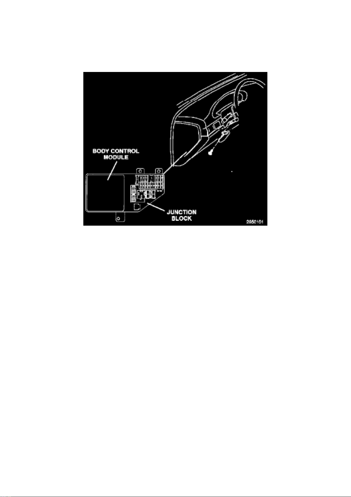
Dodge Workshop Manuals > Relays and Modules > Relays and Modules - Powertrain Management > Relays and Modules Computers and Control Systems > Body Control Module > Component Information > Locations > Component Locations
Body Control Module: Component Locations
ETACS-ECU
Page 62

Dodge Stratus Workshop Manual (L4-2.4L VIN X (1998))
Dodge Workshop Manuals > Relays and Modules > Relays and Modules - Powertrain Management > Relays and Modules Computers and Control Systems > Body Control Module > Component Information > Locations > Component Locations >
Page 84
Page 63
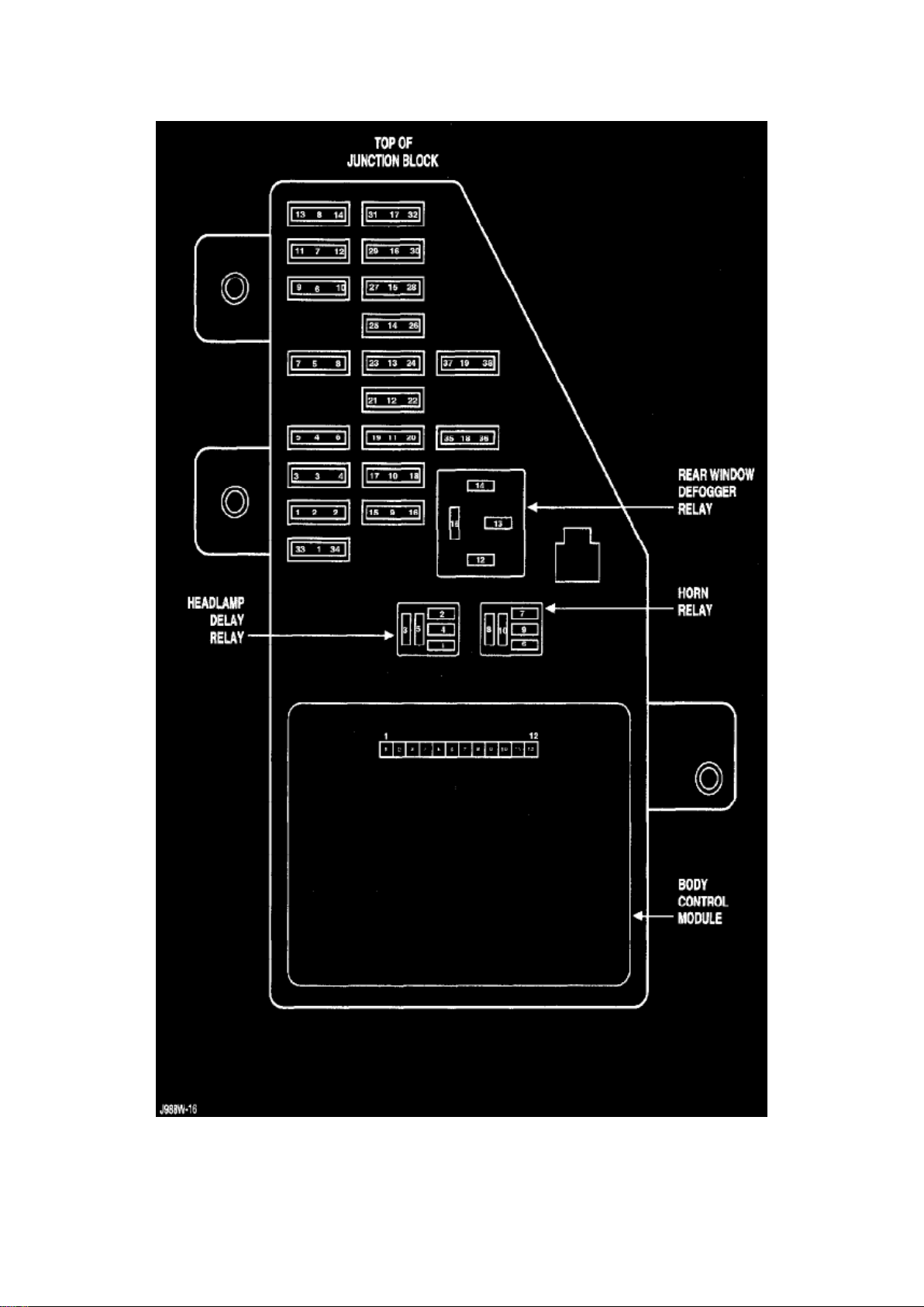
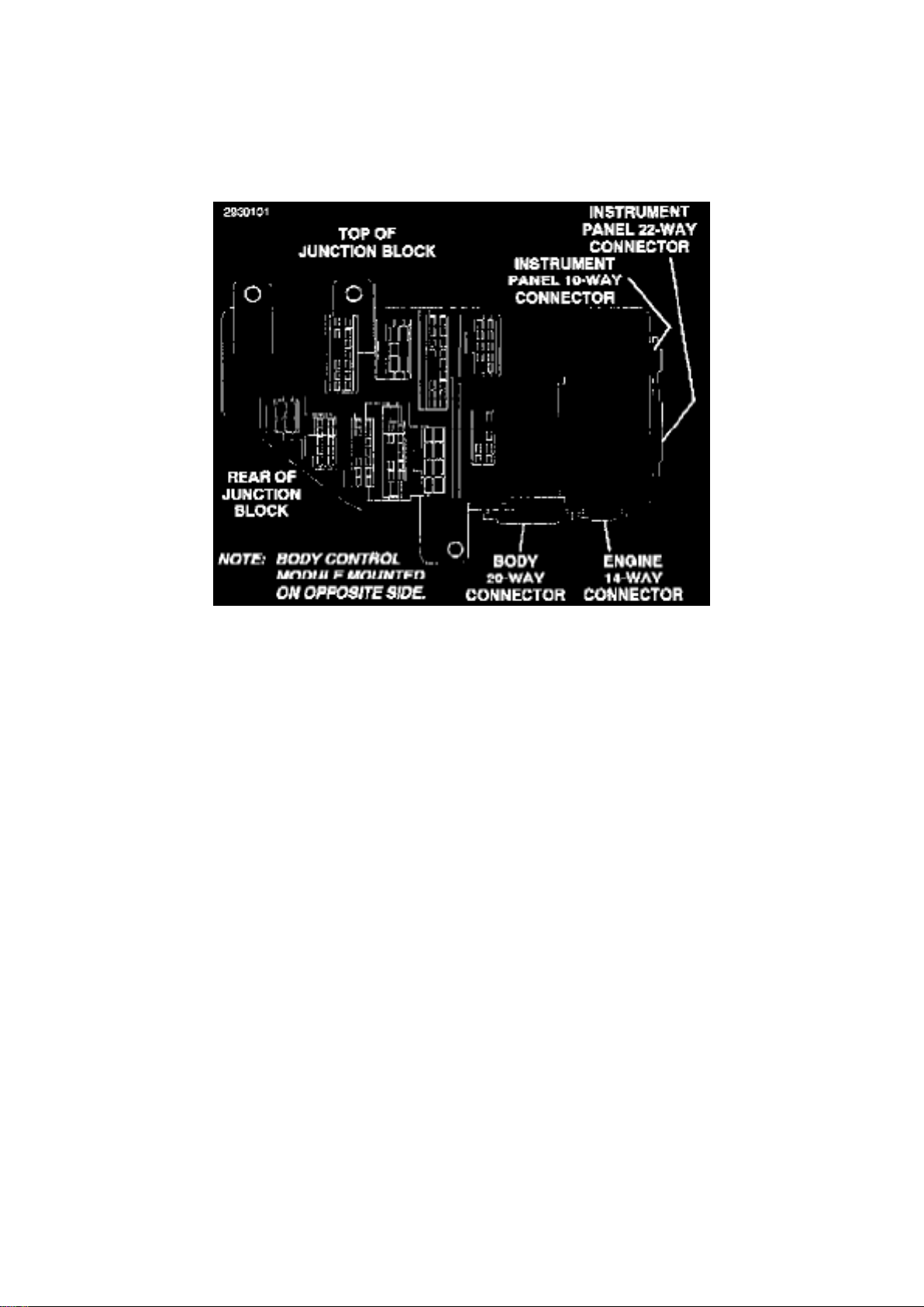
Junction Block
Page 64
Dodge Stratus Workshop Manual (L4-2.4L VIN X (1998))
Dodge Workshop Manuals > Relays and Modules > Relays and Modules - Powertrain Management > Relays and Modules Computers and Control Systems > Body Control Module > Component Information > Locations > Component Locations >
Page 85
Junction Block
Page 65

Dodge Stratus Workshop Manual (L4-2.4L VIN X (1998))
Dodge Workshop Manuals > Relays and Modules > Relays and Modules - Powertrain Management > Relays and Modules Computers and Control Systems > Body Control Module > Component Information > Diagrams > Diagram Information and
Instructions
Page 66
Body Control Module: Diagram Information and Instructions
Page 67

Introduction
General Information
Page 68
Dodge Stratus Workshop Manual (L4-2.4L VIN X (1998))
Dodge Workshop Manuals > Relays and Modules > Relays and Modules - Powertrain Management > Relays and Modules Computers and Control Systems > Body Control Module > Component Information > Diagrams > Diagram Information and
Instructions > Page 88
Page 69

General Information
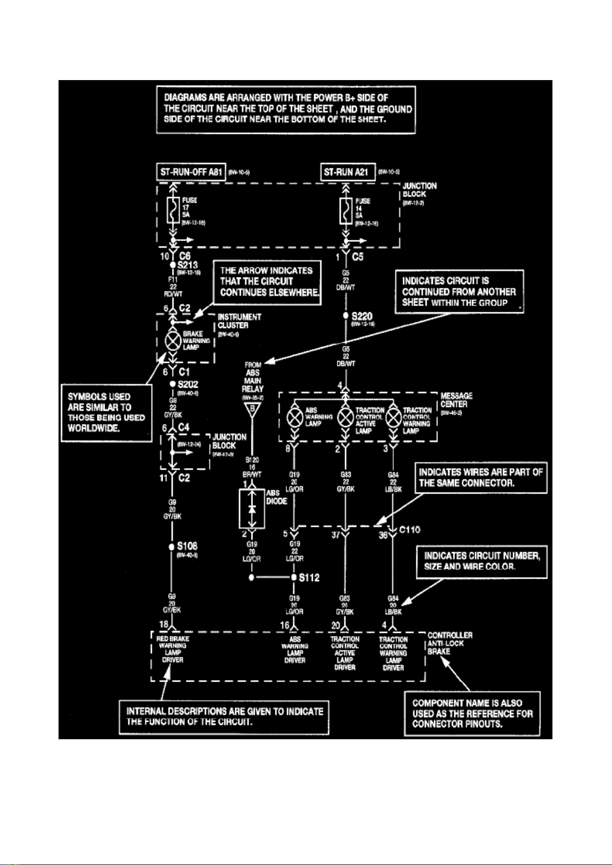
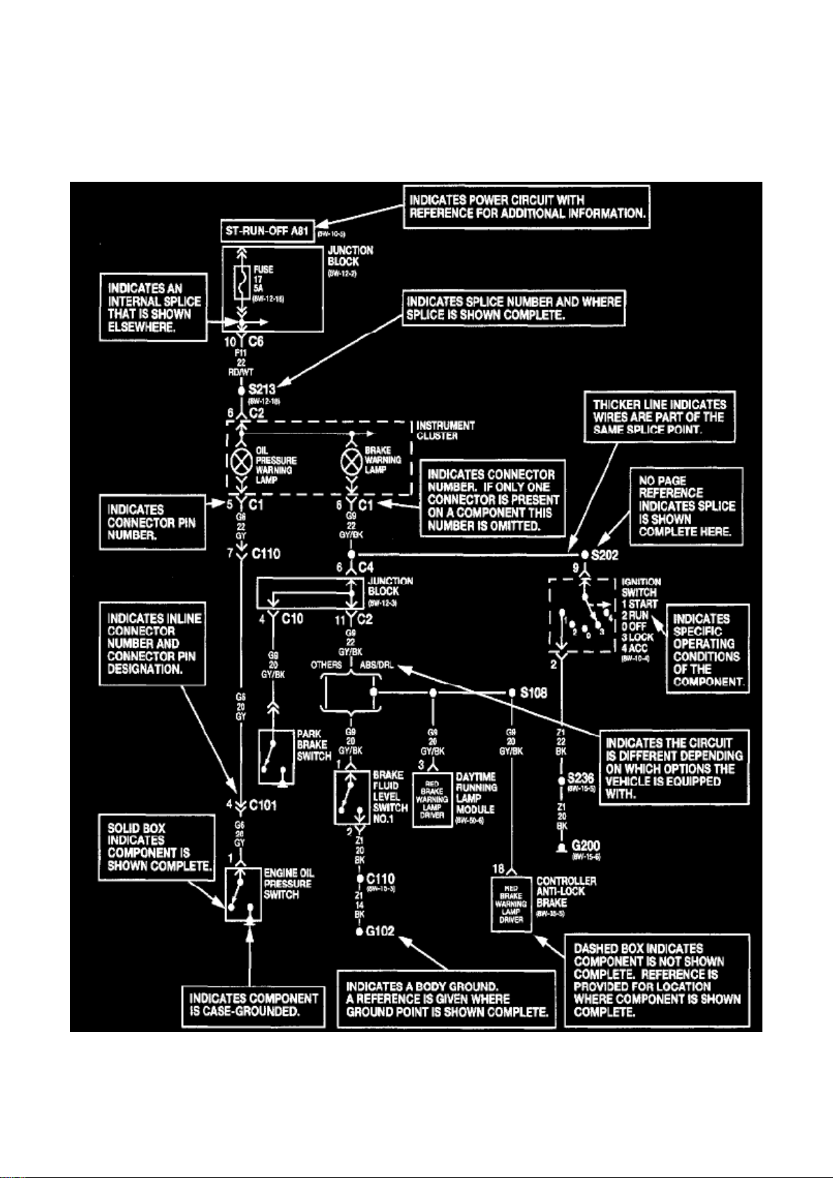
Chrysler wiring diagrams are designed to provide information regarding the vehicles wiring content.
In order to effectively use Chrysler wiring diagrams to diagnose and repair a Chrysler vehicle, it is
important to understand all of their features and characteristics.
Diagrams are arranged such that the power (B+) side of the circuit is placed near the top of the
page, and the ground (B-) side of the circuit is placed near the bottom of the page.
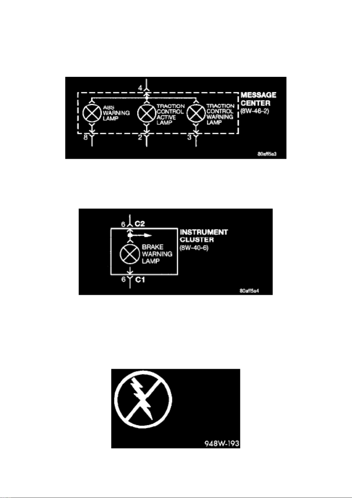
All switches, components, and modules are shown in the at rest position with the doors closed and
the key removed from the ignition.
Components are shown two ways. A solid line around a component indicates that the component is
complete. A dashed line around a component indicates that the component being shown is not
complete. Incomplete components have a reference number to indicate the page where the
component is shown complete.
It is important to realize that no attempt is made on the diagrams to represent components and
wiring as they appear on the vehicle. For example, a short piece of wire is treated the same as a
long one. In addition, switches and other components are shown as simply as possible, with regard
to function only.
Page 70
Dodge Stratus Workshop Manual (L4-2.4L VIN X (1998))
Dodge Workshop Manuals > Relays and Modules > Relays and Modules - Powertrain Management > Relays and Modules Computers and Control Systems > Body Control Module > Component Information > Diagrams > Diagram Information and
Instructions > Page 89
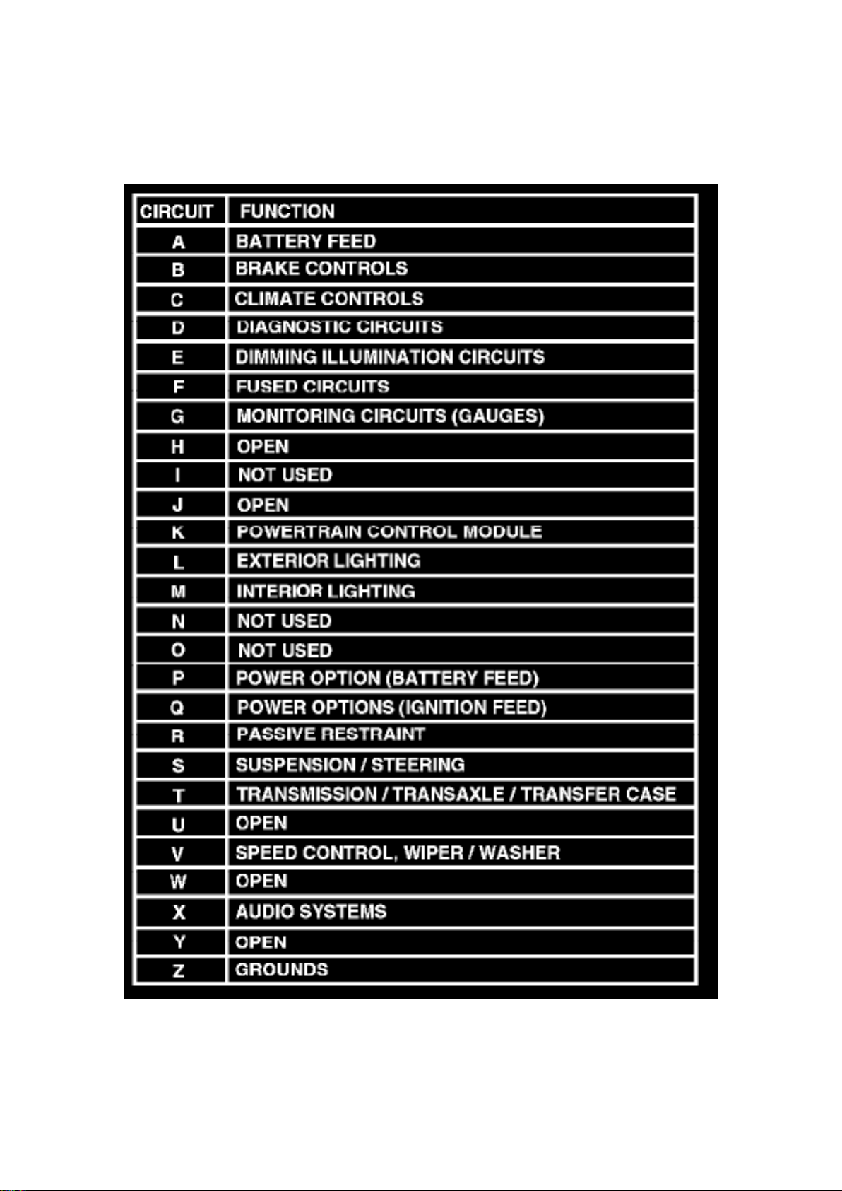
Circuit Function
Circuit Identification Code Chart
Page 71

All circuits in the diagrams use an alpha/numeric code to identify the wire and its function. To
identify which circuit code applies to a system, refer to the Circuit Identification Code Chart. This
chart shows the main circuits only and does not show the secondary codes that may apply to some
models.
Circuit Information
Page 72

Dodge Stratus Workshop Manual (L4-2.4L VIN X (1998))
Dodge Workshop Manuals > Relays and Modules > Relays and Modules - Powertrain Management > Relays and Modules Computers and Control Systems > Body Control Module > Component Information > Diagrams > Diagram Information and
Instructions > Page 90
Page 73
Wire Code Identification
Page 74

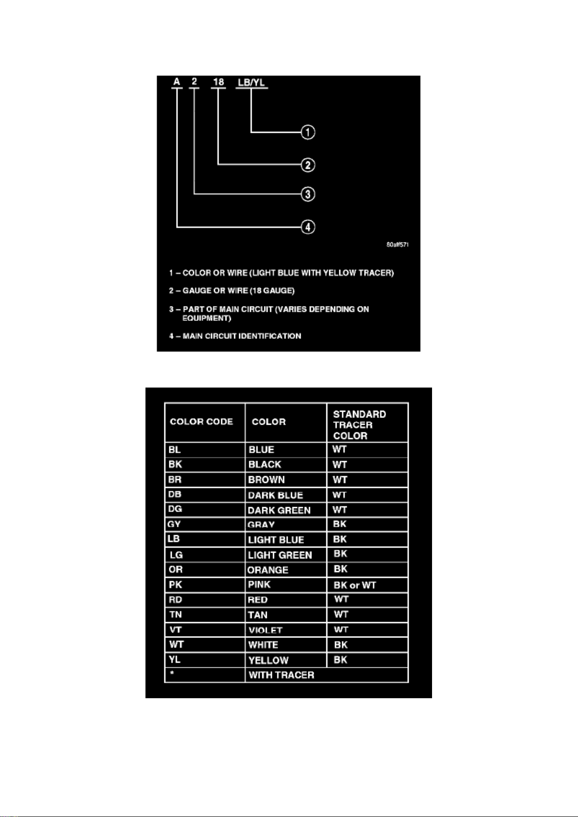
Wire Color Code Chart
Each wire shown in the diagrams contains a code which identifies the main circuit, part of the main
circuit, gauge of wire, and color.
Connector Information
CAUTION: Not all connectors are serviced. Some connectors are serviced only with a harness. A
typical example might be the Supplemental Restraint System connectors. Always check parts
availability before attempting a repair.
IDENTIFICATION
In-line connectors are identified by a number, as follows: In-line connectors located on the engine compartment harness are C100 series numbers.
- Connectors located on the instrument panel harness are C200 series numbers.
- Connectors located on the body harness are C300 series numbers.
Page 75
Dodge Stratus Workshop Manual (L4-2.4L VIN X (1998))
Dodge Workshop Manuals > Relays and Modules > Relays and Modules - Powertrain Management > Relays and Modules Computers and Control Systems > Body Control Module > Component Information > Diagrams > Diagram Information and
Instructions > Page 91
Page 76

- Jumper harness connectors are C400 series numbers.
- Grounds and ground connectors are identified with a "G" and follow the same series numbering
as the in-line connector.
Component Identification
Component connectors are identified by the component name instead of a number.
Connector Identification
Multiple connectors on a component use a C1, C2, etc. identifier.
Electrostatic Discharge (ESD) Sensitive Devices
Electrostatic Discharge Symbol
All Electrostatic Discharge (ESD) sensitive components are solid state and a symbol is used to
indicate this. When handling any component with this symbol, comply with the following procedures
to reduce the possibility of electrostatic charge build-up on the body and inadvertent discharge into
the component. If it is not known whether the part is ESD sensitive, assume that it is.
1. Always touch a known good ground before handling the part. This should be repeated while
handling the part, especially after sliding across a seat,
sitting down from a standing position, or walking a distance.
2. Avoid touching electrical terminals of the part, unless instructed to do so by a written procedure.
3. When using a voltmeter, be sure to connect the ground lead first. 4. Do not remove the part from
its protective packing until it is time to install the part. 5. Before removing the part from its package,
ground the package to a known good ground on the vehicle.
Fasteners
Page 77
Dodge Stratus Workshop Manual (L4-2.4L VIN X (1998))
Dodge Workshop Manuals > Relays and Modules > Relays and Modules - Powertrain Management > Relays and Modules Computers and Control Systems > Body Control Module > Component Information > Diagrams > Diagram Information and
Instructions > Page 92
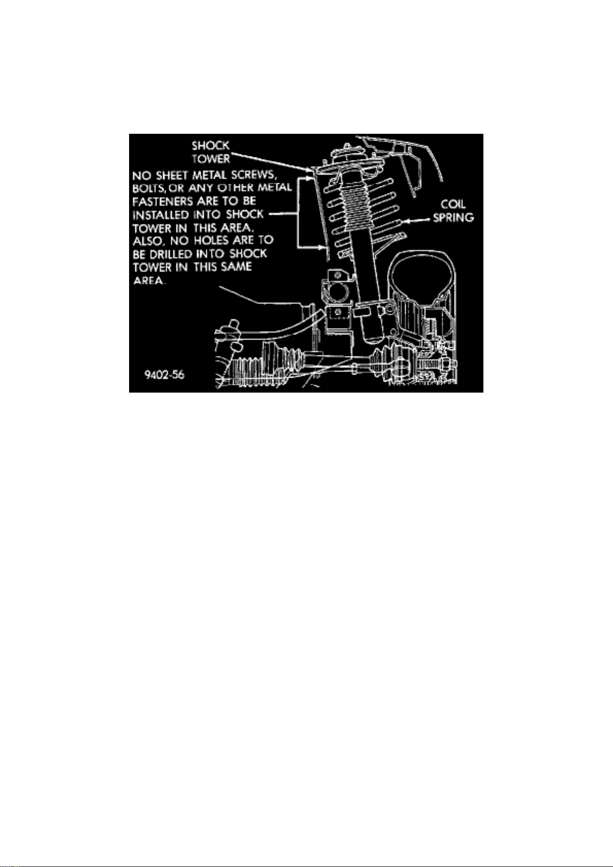
Shock Tower To Spring Minimum Clearance Area
CAUTION: At no time when servicing a vehicle, can a sheet metal screw, bolt, or other metal
fastener be installed in the strut tower to take the place of an original plastic clip. Also, NO holes
can be drilled into the front strut tower in the area shown in for the installation of any metal
fasteners into the strut tower.
Because of the minimum clearance in this area , installation of metal fasteners could damage the
coil spring coating and lead to a corrosion failure of the spring. If a plastic clip is missing, or is lost
or broken during servicing of a vehicle, replace it only with the equivalent part listed in the parts
catalog.
Fuses
CAUTION: When replacing a blown fuse, it is important to replace it with a fuse having the correct
amperage rating. The use of a fuse with a rating other than that indicated may result in an electrical
overload. If a properly rated fuse continues to blow, it indicates a problem that should be corrected.
Notes, Cautions and Warnings
Additional important information is presented in three ways: Notes, Cautions, and Warnings.
NOTES are used to help describe how switches or components operate to complete a particular
circuit. They are also used to indicate different conditions that may appear on the vehicle. For
example, an up-to and after condition.
CAUTIONS are used to indicate information that could prevent making an error that may damage
the vehicle.
WARNINGS provide information to prevent personal injury and vehicle damage. Below is a list of
general warnings that should be followed any time a vehicle is being serviced.
Page 78

WARNING:
- ALWAYS WEAR SAFETY GLASSES FOR EYE PROTECTION.
- USE SAFETY STANDS ANYTIME A PROCEDURE REQUIRES BEING UNDER A VEHICLE.
- BE SURE THAT THE IGNITION SWITCH ALWAYS IS IN THE OFF POSITION, UNLESS THE
PROCEDURE REQUIRES IT TO BE ON.
- SET THE PARKING BRAKE WHEN WORKING ON ANY VEHICLE. AN AUTOMATIC
TRANSMISSION SHOULD BE IN PARK. A MANUAL TRANSMISSION SHOULD BE IN
NEUTRAL.
- OPERATE THE ENGINE ONLY IN A WELL-VENTILATED AREA.
- KEEP AWAY FROM MOVING PARTS WHEN THE ENGINE IS RUNNING, ESPECIALLY THE
FAN AND BELTS.
- TO PREVENT SERIOUS BURNS, AVOID CONTACT WITH HOT PARTS SUCH AS THE
RADIATOR, EXHAUST MANIFOLD(S), TAIL PIPE, CATALYTIC CONVERTER, AND MUFFLER.
- DO NOT ALLOW FLAME OR SPARKS NEAR THE BATTERY. GASES ARE ALWAYS
PRESENT IN AND AROUND THE BATTERY.
- ALWAYS REMOVE RINGS, WATCHES, LOOSE HANGING JEWELRY, AND LOOSE
CLOTHING.
Positive Temperature Coefficient
Positive Temperature Coefficient (PTC) devices are being used for circuit protection. These PTC's
act like a solid state fuse. They are located in the
Page 79
Dodge Stratus Workshop Manual (L4-2.4L VIN X (1998))
Dodge Workshop Manuals > Relays and Modules > Relays and Modules - Powertrain Management > Relays and Modules Computers and Control Systems > Body Control Module > Component Information > Diagrams > Diagram Information and
Instructions > Page 93
Page 80

junction block, and are used to protect such items as: power door lock motors, power windows, and
various engine solenoids.
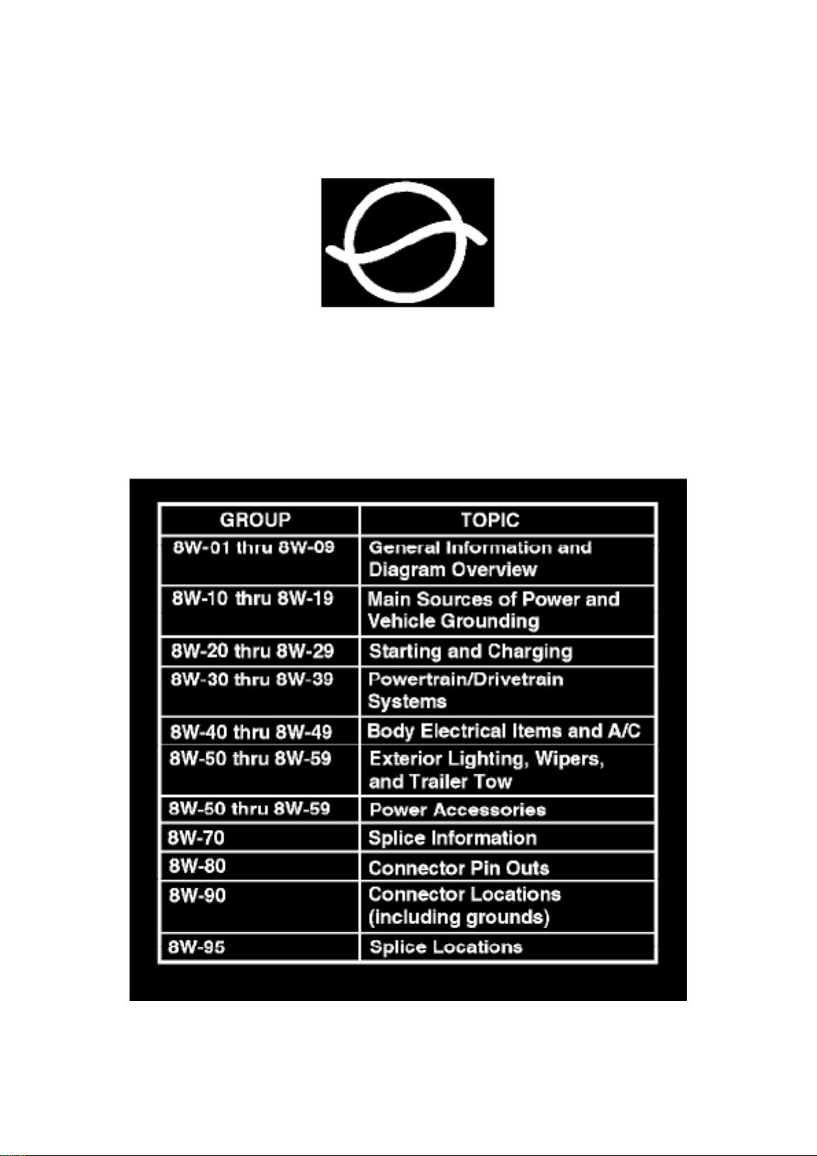
Positive Temperature Coefficient Symbol
A special symbol is used to identify these in the wiring diagrams.
Section Identification
Wiring Diagram Section Identification
The wiring diagrams are grouped into individual sections. If a component is most likely found in a
particular group, it will be shown complete (all wires, connectors, and pins) within that group. For
example, the Auto Shut Down Relay is most likely to be found in Group 30, so it is shown there
complete. It can, however, be shown partially in another group if it contains some associated
wiring.
Symbols
Page 81

Dodge Stratus Workshop Manual (L4-2.4L VIN X (1998))
Dodge Workshop Manuals > Relays and Modules > Relays and Modules - Powertrain Management > Relays and Modules Computers and Control Systems > Body Control Module > Component Information > Diagrams > Diagram Information and
Instructions > Page 94
Page 82
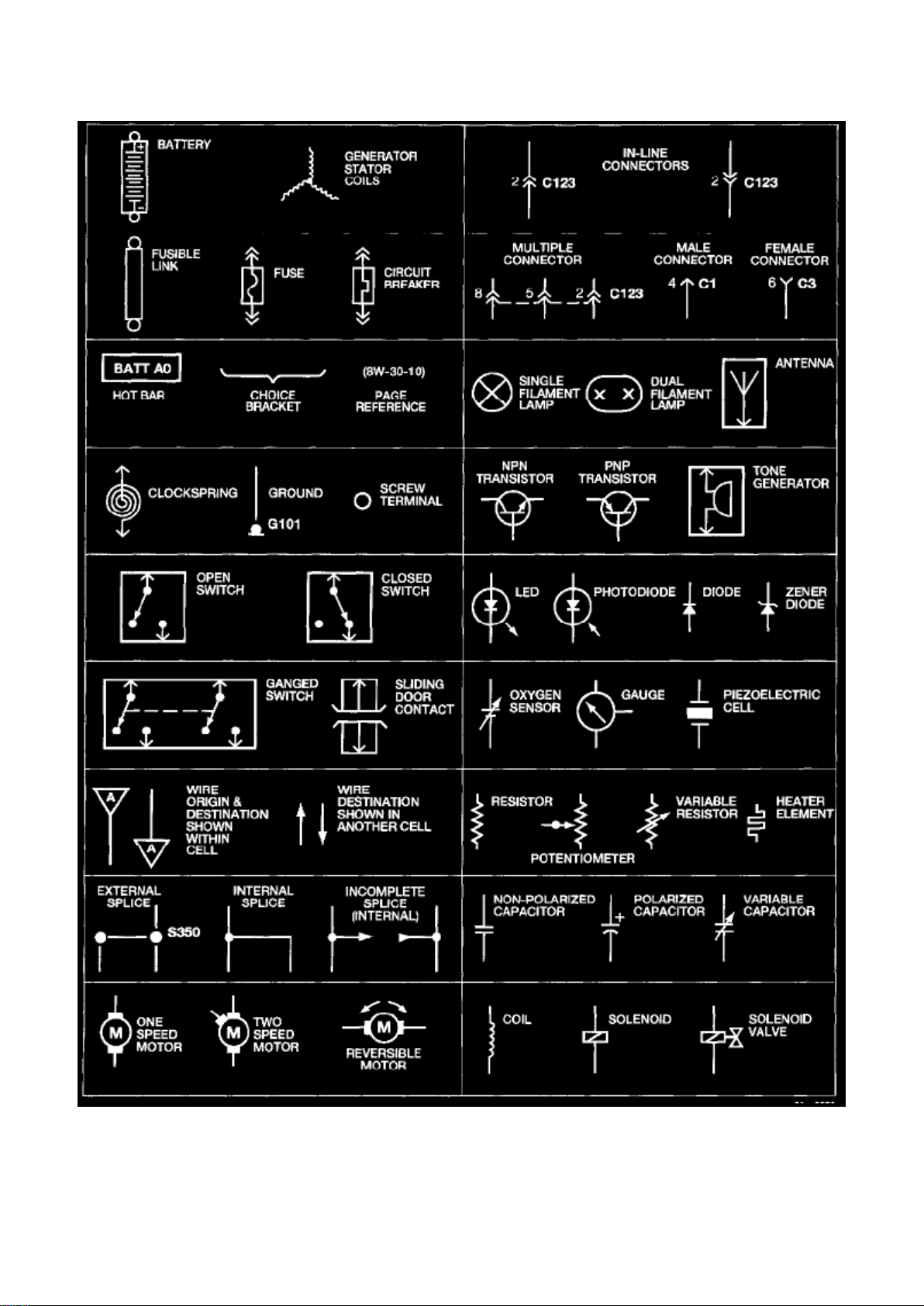
Wiring Diagram Symbols
Page 83

International symbols are used throughout the wiring diagrams. These symbols are consistent with
those being used around the world.
Take-Outs
The abbreviation T/O is used in the component location to indicate a point at which the wiring
harness branches out to a component.
How to Find System & Component Diagrams
When trying to find the diagram for a specific component or system, use the Group Index
information or the Alphabetic Index to Wiring Diagrams under Electrical
Whenever a reference exists to another sheet or figure, find the corresponding diagram using the
Group Index, Diagrams By Sheet Number, or Diagrams By Figure Number. The reference number
for the subsequent diagram will match a listed group shown.
Page 84

Dodge Stratus Workshop Manual (L4-2.4L VIN X (1998))
Dodge Workshop Manuals > Relays and Modules > Relays and Modules - Powertrain Management > Relays and Modules Computers and Control Systems > Body Control Module > Component Information > Diagrams > Diagram Information and
Instructions > Page 95
Page 85
Connector and Terminal Replacement
Page 86

1. Disconnect battery. 2. Disconnect the connector (that is to be repaired) from its mating
half/component. 3. Cut off the existing wire connector directly behind the insulator. Remove six
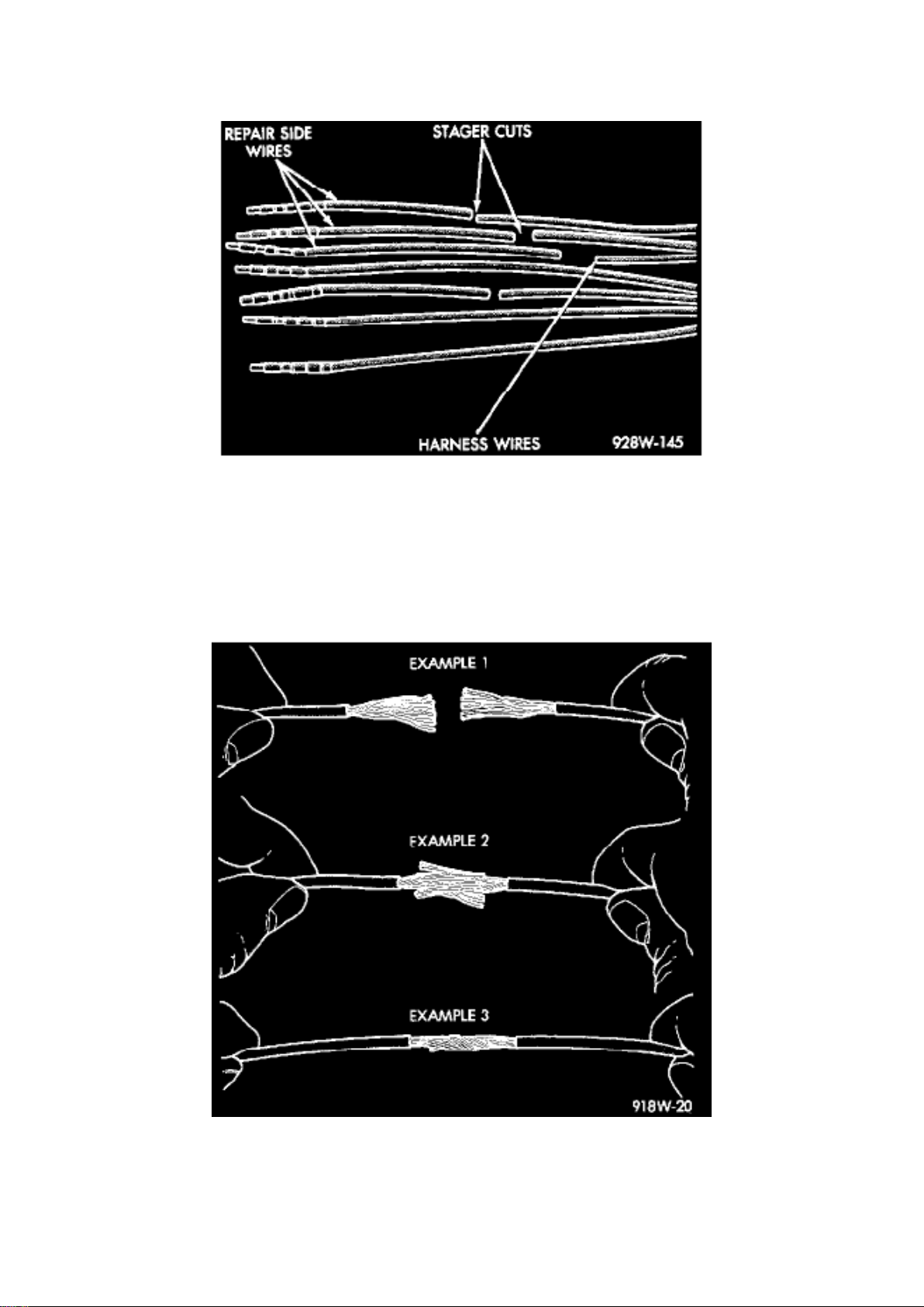
inches of tape from the harness. 4. Stagger cut all wires on the harness side at 1/2 inch intervals.
5. Remove 1 inch of insulation from each wire on the harness side.
Stagger Cutting Wires (Typical)
6. Stagger cut the matching wires on the repair connector assembly in the opposite order as was
done on the harness side of the repair. Allow extra
length for soldered connections. Check that the overall length is the same as the original.
7. Remove 1 inch of insulation from each wire. 8. Place a piece of heat-shrink tubing over one side
of the wire. Be sure the tubing will be long enough to cover and seal the entire repair area.
Wire Repair
9. Spread the strands of the wire apart on each part of the exposed wires (Example 1).
10. Push the two ends of wire together until the strands of wire are close to the insulation (Example
2). 11. Twist the wires together (Example 3). 12. Solder the connection together using rosin core
solder only. Do not use acid core solder. 13. Center the heat-shrink tubing over the joint and heat
using a heat gun. Heat the joint until the tubing is tightly sealed and sealant comes out of both
ends of the tubing.
14. Repeat steps 8 through 13 for each wire. 15. Re-tape the wire harness starting 1-1/2 inches
behind the connector and 2 inches past the repair. 16. Re-connect the repaired connector. 17.
Connect the battery and test all affected systems.
Connector Replacement
Page 87

Dodge Stratus Workshop Manual (L4-2.4L VIN X (1998))
Dodge Workshop Manuals > Relays and Modules > Relays and Modules - Powertrain Management > Relays and Modules Computers and Control Systems > Body Control Module > Component Information > Diagrams > Diagram Information and
Instructions > Page 96
Page 88
1. Disconnect the battery. 2. Disconnect the connector (that is to be repaired) from its mating
half/component.
Page 89

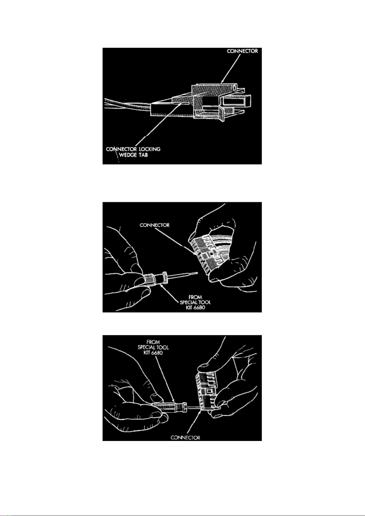
Connector Locking Wedge
3. Remove the connector locking wedge, if required.
Terminal Removal
Terminal Removal Using Special Tool
4. Position the connector locking finger away from the terminal using the proper pick from Special
Tool Kit 6680. Pull on the wire to remove the
terminal from the connector.
5. Reset the terminal locking tang, if it has one. 6. Insert the removed wire in the same cavity on
the repair connector. 7. Repeat steps 4 through 6 for each wire in the connector, being sure that all
wires are inserted into the proper cavities. 8. Insert the connector locking wedge into the repaired
connector, if required. 9. Connect the connector to its mating half/component.
10. Connect the battery and test all affected systems.
Page 90

Dodge Stratus Workshop Manual (L4-2.4L VIN X (1998))
Dodge Workshop Manuals > Relays and Modules > Relays and Modules - Powertrain Management > Relays and Modules Computers and Control Systems > Body Control Module > Component Information > Diagrams > Diagram Information and
Instructions > Page 97
Page 91
Diode Replacement
Page 92

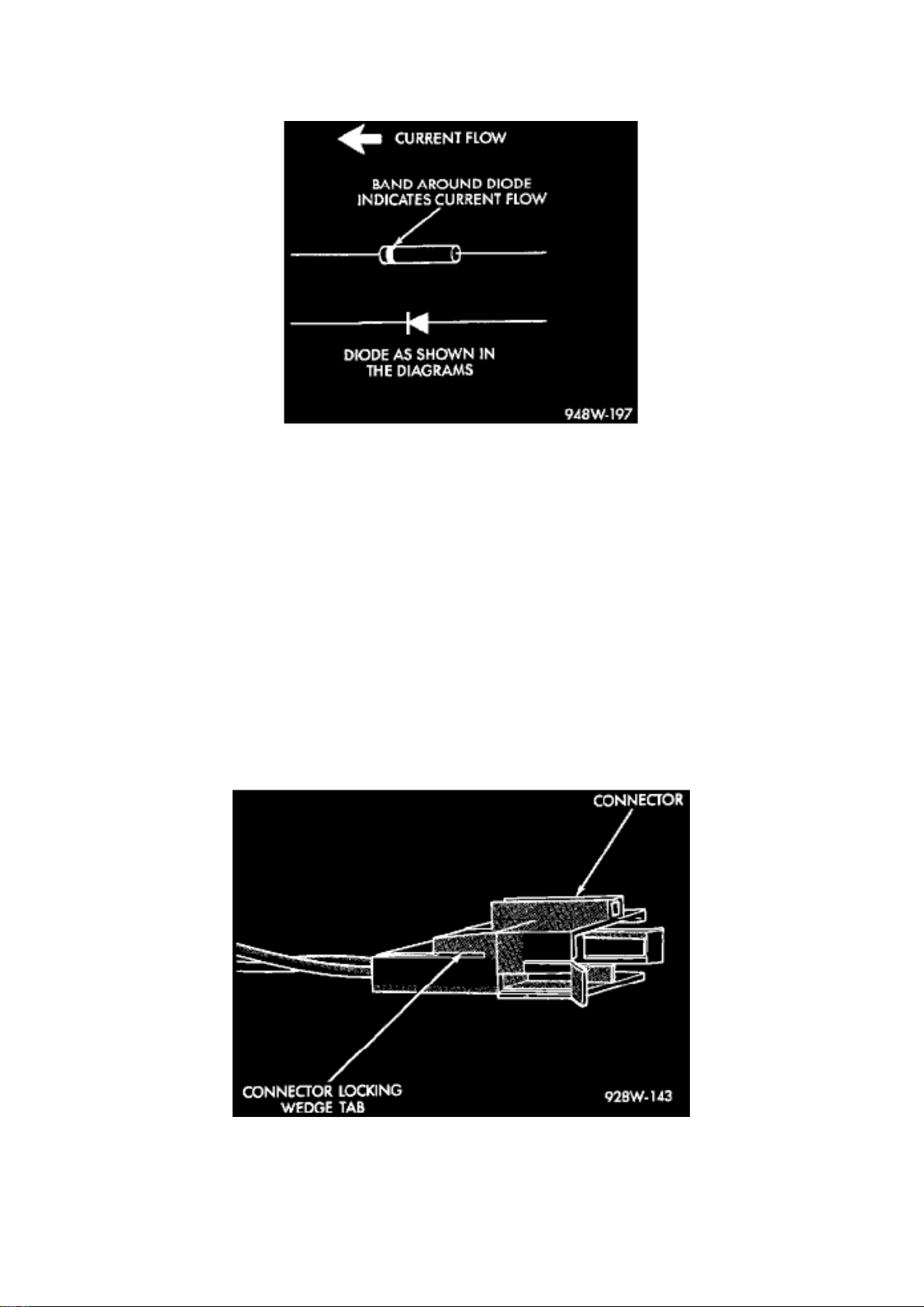
Diode Identification
1. Disconnect the battery. 2. Locate the diode in the harness and remove the protective covering.
3. Remove the diode from the harness, pay attention to the current flow direction. 4. Remove the
insulation from the wires in the harness. Only remove enough insulation to solder in the new diode.
5. Install the new diode in the harness, making sure current flow is correct. 6. Solder the connection
together using rosin core solder only. Do not use acid core solder. 7. Tape the diode to the harness
using electrical tape, making sure the diode is completely sealed from the elements. 8. Re-connect
the battery and test affected systems.
Terminal Replacement
1. Disconnect the battery. 2. Disconnect the connector being repaired from its mating
half/component.
Connnector Locking Wedge Tab (Typical)
3. Remove the connector locking wedge, if required.
Page 93

Dodge Stratus Workshop Manual (L4-2.4L VIN X (1998))
Dodge Workshop Manuals > Relays and Modules > Relays and Modules - Powertrain Management > Relays and Modules Computers and Control Systems > Body Control Module > Component Information > Diagrams > Diagram Information and
Instructions > Page 98
Page 94
Terminal Removal
Page 95

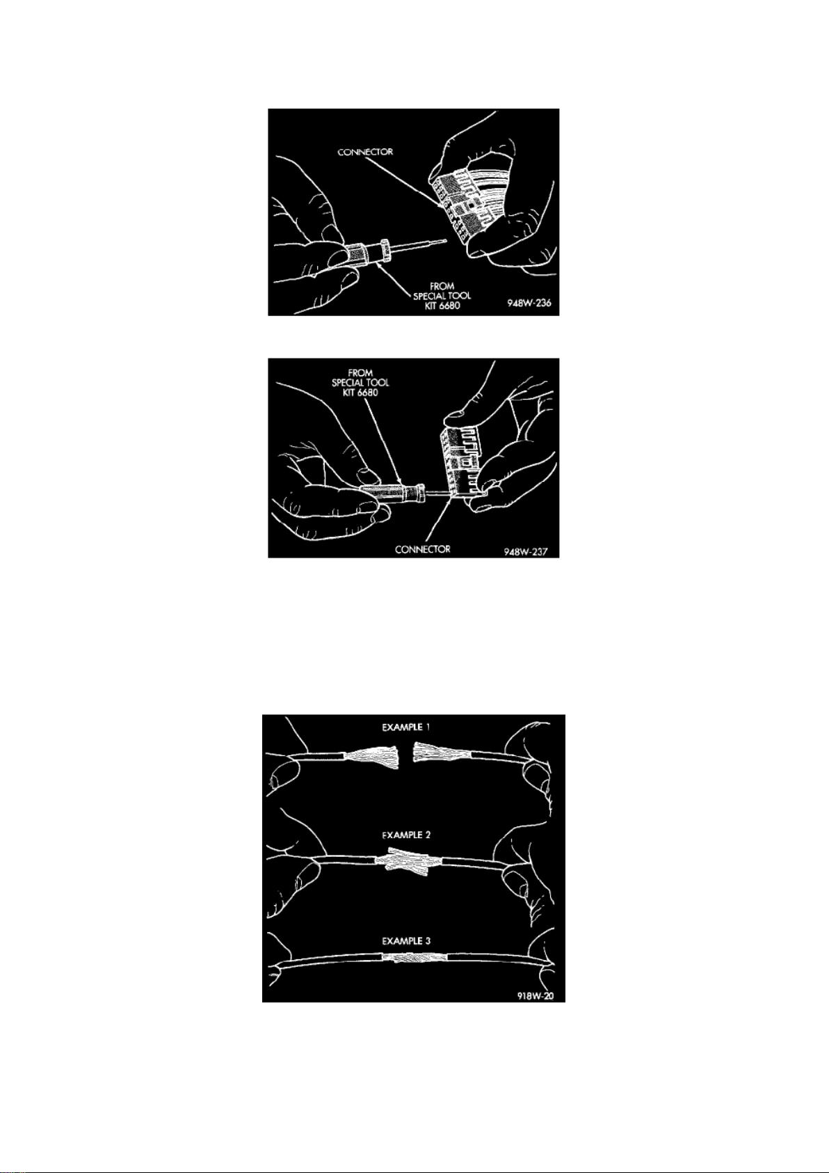
Terminal Removal Using Special Tool
4. Position the connector locking finger away from the terminal using the proper pick from Special
Tool Kit 6680. Pull on the wire to remove the
terminal from the connector.
5. Cut the wire 6 inches from the back of the connector. 6. Remove 1 inch of insulation from the
wire on the harness side. 7. Select a wire from the terminal repair assembly that best matches the
color of the wire being repaired. 8. Cut the repair wire to the proper length and remove 1 inch of
insulation. 9. Place a piece of heat-shrink tubing over one side of the wire. Be sure the tubing will
be long enough to cover and seal the entire repair area.
Wire Repair
Page 96
Dodge Stratus Workshop Manual (L4-2.4L VIN X (1998))
Dodge Workshop Manuals > Relays and Modules > Relays and Modules - Powertrain Management > Relays and Modules Computers and Control Systems > Body Control Module > Component Information > Diagrams > Diagram Information and
Instructions > Page 99
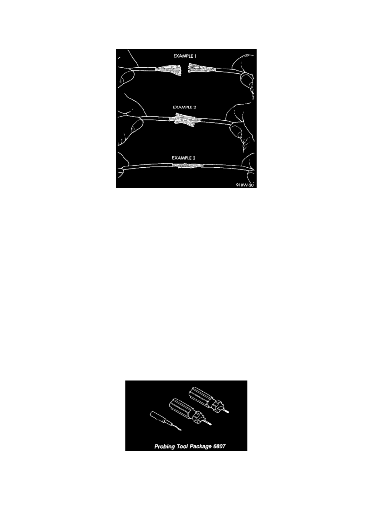
10. Spread the strands of the wire apart on each part of the exposed wires (Example 1). 11. Push
the two ends of wire together until the strands of wire re close to the insulation (Example 2). 12.
Twist the wires together (Example 3). 13. Solder the connection together using rosin core solder
Page 97

only. Do not use acid core solder. 14. Center the heat-shrink tubing over the joint and heat using a
heat gun. Heat the joint until the tubing is tightly sealed and sealant comes out of both
ends of the tubing.
15. Insert the repaired wire into the connector. 16. Install the connector locking wedge, if required
and re-connect the connector to its mating half/component. 17. Re-tape the wire harness starting
1-1/2 inches behind the connector and 2 inches past the repair. 18. Connect the battery and test all
affected systems.
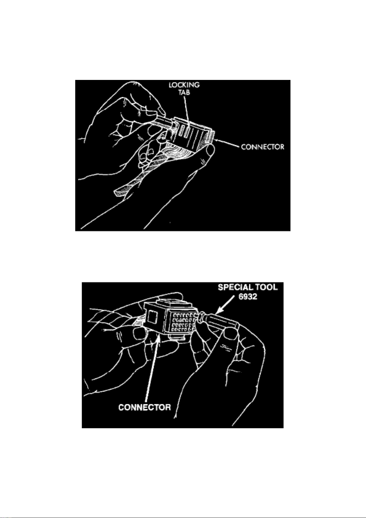
Terminal/Connector Repair-Augat Connectors
1. Disconnect battery 2. Disconnect the connector from its mating half/component.
Augat Connector Repair
3. Push down on the yellow connector locking tab to release the terminals.
Using Special Tool 6932
4. Using Special Tool 6932, push the terminal to remove it from the connector. 5. Repair or replace
the connector or terminal as necessary 6. When re-assembling the connector, the locking wedge
must be placed in the locked position to prevent terminal push out.
Wiring Repair
Page 98

Dodge Stratus Workshop Manual (L4-2.4L VIN X (1998))
Dodge Workshop Manuals > Relays and Modules > Relays and Modules - Powertrain Management > Relays and Modules Computers and Control Systems > Body Control Module > Component Information > Diagrams > Diagram Information and
Instructions > Page 100
Page 99
Wire Repair
Page 100

When replacing or repairing a wire, it is important that the correct gauge be used as shown in the
wiring diagrams. The wires must also be held securely in place to prevent damage to the insulation.
1. Disconnect the battery negative cable.
2. Remove 1 inch of insulation from each end of the wire.
3. Place a piece of heat-shrink tubing over one side of the wire. Be sure the tubing will be long
enough to cover and seal the entire repair area.
4. Spread the strands of the wire apart on each part of the exposed wires (Example 1).
5. Push the two ends of wire together until the strands of wire are close to the insulation (Example
2).
6. Twist the wires together (Example 3).
7. Solder the connection together using rosin core solder only. Do not use acid core solder.
8. Center the heat-shrink tubing over the joint and heat using a heat gun. Heat the joint until the
tubing is tightly sealed and sealant comes out of both
ends of the tubing.
9. Secure the wire to the existing ones to prevent chafing or damage to the insulation.
10. Connect the battery and test all affected systems.
Special Tools
Probing Tool Package 6807
 Loading...