

Page 1
DR/DH STEERING 19 - 1
STEERING
TABLE OF CONTENTS
page page
STEERING
DESCRIPTION ..........................1
OPERATION ............................1
DIAGNOSIS AND TESTING
POWER STEERING SYSTEM .............2
POWER STEERING FLOW AND PRESSURE . 4
SPECIAL TOOLS
STEERING ...........................6
COLUMN ...............................7
GEAR - INDEPENDENT FRONT SUSPENSION ..31
GEAR - LINK/COIL .......................35
LINKAGE - INDEPENDENT FRONT
SUSPENSION ...........................53
LINKAGE - LINK/COIL ....................55
PUMP .................................63
PUMP - SRT-10 ..........................78
STEERING
DESCRIPTION
CAUTION: MOPART ATF+4 is to be used in the power steering system. No other power steering or automatic transmission fluid is to be used in the system. Damage may result to the power steering pump and
system if any other fluid is used, and do not overfill.
Power steering systems consist of:
• Steering column
• Rack and pinion steering gear
• Belt driven hydraulic steering pump
• Pump pressure and return hoses
• Oil Cooler
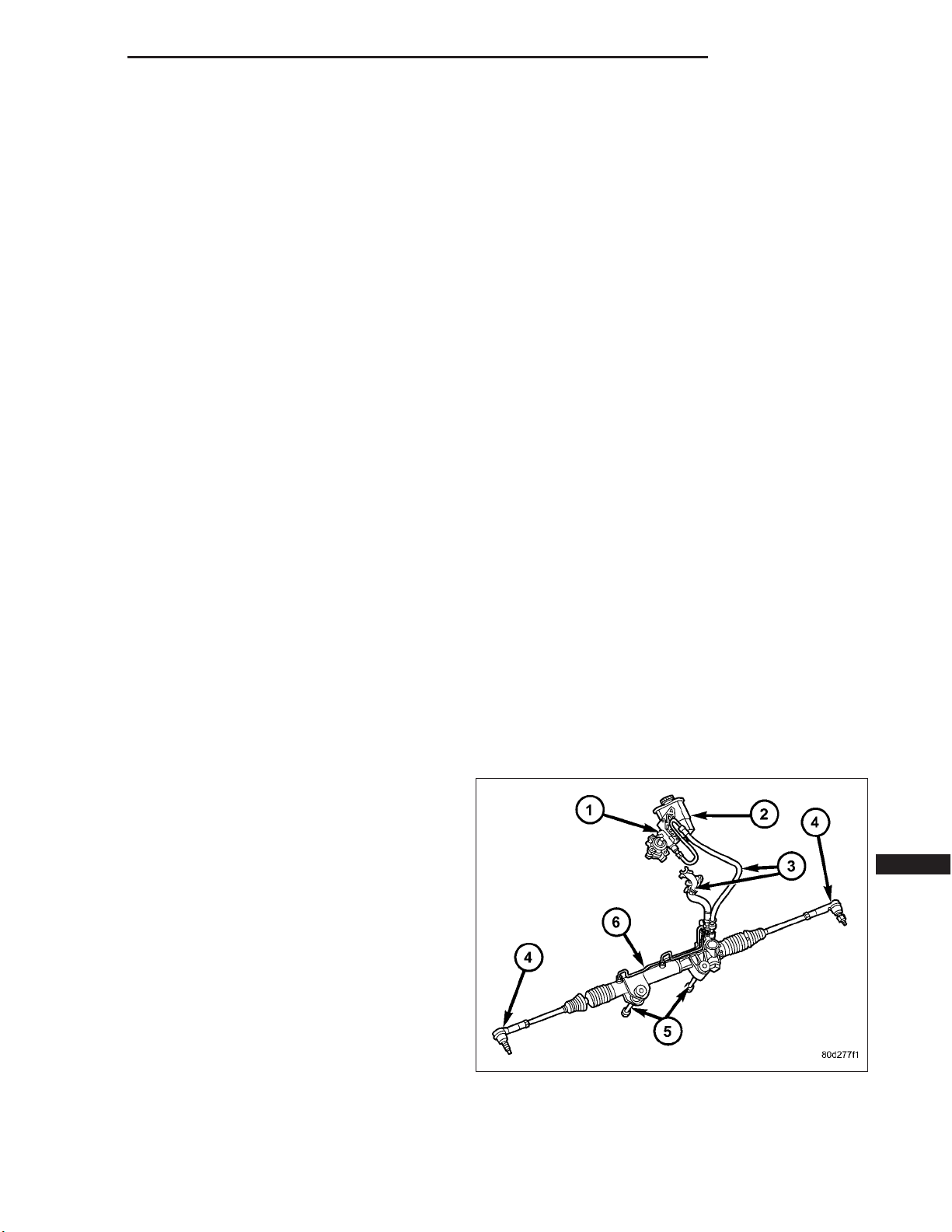
OPERATION
The steering column shaft is attached to the gear pinion. The rotation of the pinion moves the gear rack
from side-to-side. This lateral action of the rack
pushes and pulls the tie rods (4) to change the direction of the front wheels.
Power assist is provided by an engine mounted
hydraulic pump which supplies hydraulic fluid pressure
to the steering gear (6).
Page 2

19 - 2 STEERING DR/DH
DIAGNOSIS AND TESTING
POWER STEERING SYSTEM
There is some noise in all power steering systems. One of the most common is a hissing sound evident at a
standstill parking. Or when the steering wheel is at the end of it’s travel. Hiss is a high frequency noise similar
to that of a water tap being closed slowly. The noise is present in all valves that have a high velocity fluid passing
through an orifice. There is no relationship between this noise and steering performance.
STEERING NOISE
CONDITION POSSIBLE CAUSES CORRECTION
OBJECTIONAL HISS OR
WHISTLE
RATTLE OR CLUNK 1. Gear mounting bolts loose. 1. Tighten bolts to specification.
CHIRP OR SQUEAL 1. Loose belt. 1. Adjust or replace.
WHINE OR GROWL 1. Low fluid level. 1. Fill to proper level.
1. Steering intermediate shaft to dash panel
seal.
2. Noisy valve in power steering gear. 2. Replace steering gear.
2. Loose or damaged suspension
components.
3. Internal gear noise. 3. Replace steering gear.
4. Pressure hose in contact with other
components.
5. Loose or damaged intermediate shaft or
column.
2. Pressure hose in contact with other
components.
3. Internal pump noise. 3. Replace pump.
4. Air in fluid 4. Check for lekas, Evacuate air
1. Check and repair seal at dash
panel.
2. Inspect and repair suspension.
4. Reposition hose.
5. Inspect and repair or replace.
2. Reposition hose.
from P/S system.
SUCKING AIR SOUND 1. Loose return line clamp. 1. Replace clamp.
SCRUBBING OR
KNOCKING
2. O-ring missing or damaged on hose
fitting.
3. Low fluid level. 3. Fill to proper level.
4. Air leak between pump and reservoir. 4. Repair as necessary.
5. Reservoir cap not installed correctly. 5. Install reservoir cap correctly.
1. Wrong tire size. 1. Verify tire size.
2. Replace o-ring.
Page 3

DR/DH STEERING 19 - 3
BINDING AND STICKING
CONDITION POSSIBLE CAUSE CORRECTION
DIFFICULT TO TURN WHEEL
STICKS OR BINDS
INSUFFICIENT ASST. OR POOR RETURN TO CENTER
CONDITION POSSIBLE CAUSE CORRECTION
HARD TURNING OR MOMENTARY
INCREASE IN TURNING EFFORT
1. Low fluid level. 1. Fill to proper level.
2. Tire pressure. 2. Adjust tire pressure.
3. Steering components (ball
joints/tie rod ends).
4. Loose belt. 4. Adjust or replace.
5. Low pump pressure. 5. Pressure test and replace if
6. Column shaft coupler binding. 6. Replace coupler.
7. Steering gear worn. 7. Replace gear.
8. Pump seized / Stuck valve 8. Replace pump.
1. Tire pressure. 1. Adjust tire pressure.
2. Low fluid level. 2. Fill to proper level.
3. Loose belt. 3. Adjust or replace.
4. Low pump pressure. 4. Pressure test and repair as
5. Internal gear leak. 5. Replace gear.
3 Inspect and repair as necessary.
necessary.
necessary.
STEERING WHEEL DOES NOT
WANT TO RETURN TO CENTER
POSITION
LOOSE STEERING AND VEHICLE LEAD
CONDITION POSSIBLE CAUSE CORRECTION
EXCESSIVE PLAY IN STEERING
WHEEL
VEHICLE PULLS OR LEADS TO
ONE SIDE.
1. Tire pressure. 1. Adjust tire pressure.
2. Wheel alignment. 2. Align front end.
3. Lack of lubrication. 3. Inspect and lubricate suspension
4. High friction in steering gear. 4. Replace gear.
1. Worn or loose suspension or
steering components.
2. Worn or loose wheel bearings. 2. Inspect and repair or adjust
3. Steering gear mounting. 3. Tighten gear mounting bolts to
4. Gear out of adjustment. 4. Replace gear.
5. Worn or loose steering coupler. 5. Inspect and replace as
1. Tire Pressure. 1. Adjust tire pressure.
2. Radial tire lead. 2. Rotate tires.
3. Brakes dragging. 3. Repair as necessary.
4. Wheel alignment. 4. Align front end.
5. Steering gear valve bias. 5. Replace steering gear.
compnents.
1. Inspect and repair as necessary.
bearings.
specification.
necessary.
Page 4
19 - 4 STEERING DR/DH
POWER STEERING FLOW AND PRESSURE
The following procedure is used to test the operation
of the power steering system on the vehicle. This test
will provide the gallons per minute (GPM) or flow rate
of the power steering pump along with the maximum
relief pressure. Perform test any time a power steering
system problem is present. This test will determine if
the power steering pump or power steering gear is not
functioning properly. The following pressure and flow
test is performed using Power Steering Analyzer Tool
kit 6815 and Adapter Kit 6893.
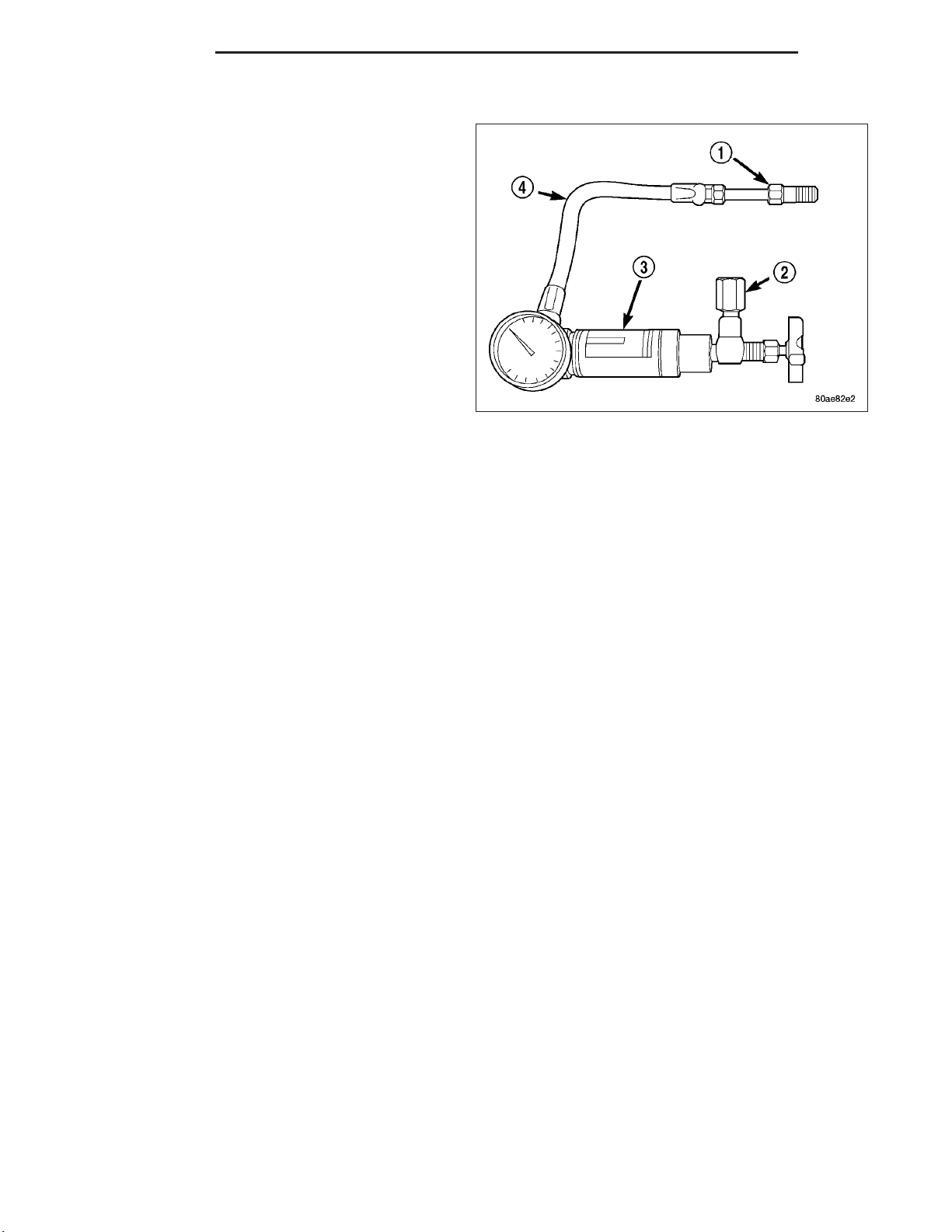
FLOW AND PRESSURE TEST
1. Check the power steering belt to ensure it is in good condition and adjusted properly.
2. Connect pressure gauge hose from the Power Steering Analyzer to adapter 6826.
3. Connect tube 6825A to Power Steering Analyzer test valve end.
4. Disconnect the high pressure hose from the power steering pump.
5. Connect the tube 6825A to the pump fitting.
6. Connect the power steering hose from the steering gear to the adapter 6826.
7. Open the test valve completely.
8. Start engine and let idle long enough to circulate power steering fluid through flow/pressure test gauge and to get
air out of the fluid. Then shut off engine.
9. Check fluid level, add fluid as necessary. Start engine again and let idle.
10. Gauge should read below 862 kPa (125 psi), if above, inspect the hoses for restrictions and repair as neces-
sary. The initial pressure reading should be in the range of 345-552 kPa (50-80 psi).
11. Increase the engine speed to 1500 RPM and read the flow meter. If the flow rate (GPM) is below specification,
(refer to pump specification chart for GPM) the pump should be replaced.
CAUTION: The following test procedure involves testing maximum pump pressure output and flow control
valve operation. Do not leave valve closed for more than three seconds as the pump could be damaged.
12. Close valve fully three times and record highest pressure indicated each time. All three readings must be
above specifications and within 345 kPa (50 psi) of each other.
• Pressures above specifications but not within 345 kPa (50 psi) of each other, replace pump.
• Pressures within 345 kPa (50 psi) of each other but below specifications, replace pump.
13. Open the test valve and turn the steering wheel to the extreme left and right positions three times against the
stops. Record the highest pressure reading at each position. Compare readings to the pump specifications
chart. If pressures readings are not within 50 psi of each other, the gear is leaking internally and must be
replaced.
CAUTION: Do not force the pump to operate against the stops for more than 2 to 3 seconds at a time
because, pump damage will result.
Page 5

DR/DH STEERING 19 - 5
PUMP SPECIFICATION
ENGINE RELIEF PRESSURE ± 65 FLOW RATE (GPM) AT 1500 RPM
1500 series 11032 kPa (1615 ± 65 psi) 3.1 - 3.5
2500 & 3500
series
12400 kPa (1800 ± 50 psi) 3.5 - 4.0
Page 6
19 - 6 STEERING DR/DH
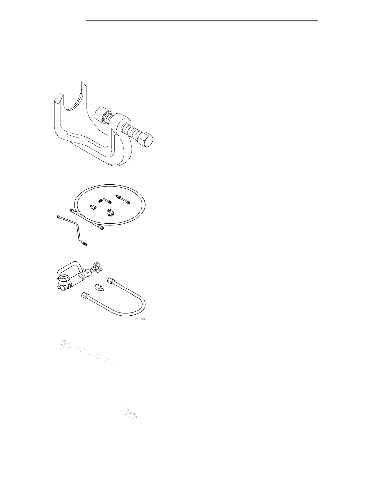
SPECIAL TOOLS
STEERING
Page 7
DR/DH COLUMN 19 - 7
COLUMN
TABLE OF CONTENTS
page page
COLUMN
DESCRIPTION
DESCRIPTION .........................7
DESCRIPTION - SRT-10 .................8
DIAGNOSIS AND TESTING
STEERING COLUMN ....................8
REMOVAL ..............................8
INSTALLATION .........................10
IGNITION SWITCH
DESCRIPTION .........................13
OPERATION ...........................13
DIAGNOSIS AND TESTING
IGNITION SWITCH ....................13
REMOVAL .............................13
INSTALLATION .........................15
IGNITION SWITCH - SRT-10
REMOVAL - SRT-10 .....................17
INSTALLATION - SRT-10 ..................19
KEY-IN IGNITION SWITCH
DESCRIPTION .........................19
DIAGNOSIS AND TESTING
IGNITION SWITCH AND KEY LOCK
CYLINDER ...........................19
KEY CYLINDER
REMOVAL .............................20
INSTALLATION .........................20
STEERING WHEEL
REMOVAL .............................21
INSTALLATION .........................21
TILT LEVER KNOB RELEASE
REMOVAL .............................21
INSTALLATION .........................23
GEAR SHIFT LEVER
REMOVAL .............................24
INSTALLATION .........................24
UPPER STEERING COUPLING
REMOVAL .............................25
INSTALLATION .........................26
LOWER STEERING COUPLING
REMOVAL
ALL LD & HD EXCEPT 4X4 HD ...........27
4X4HD .............................27
INSTALLATION
ALL LD & HD EXCEPT 4X4 HD ...........29
4X4HD .............................29
COLUMN
DESCRIPTION
DESCRIPTION
NOTE: The steering column on vehicles with an
automatic transmission may not be equipped with
an internal locking shaft that allows the ignition
key cylinder to be locked with the key. Alternative
methods of locking the steering wheel for service
will have to be used.
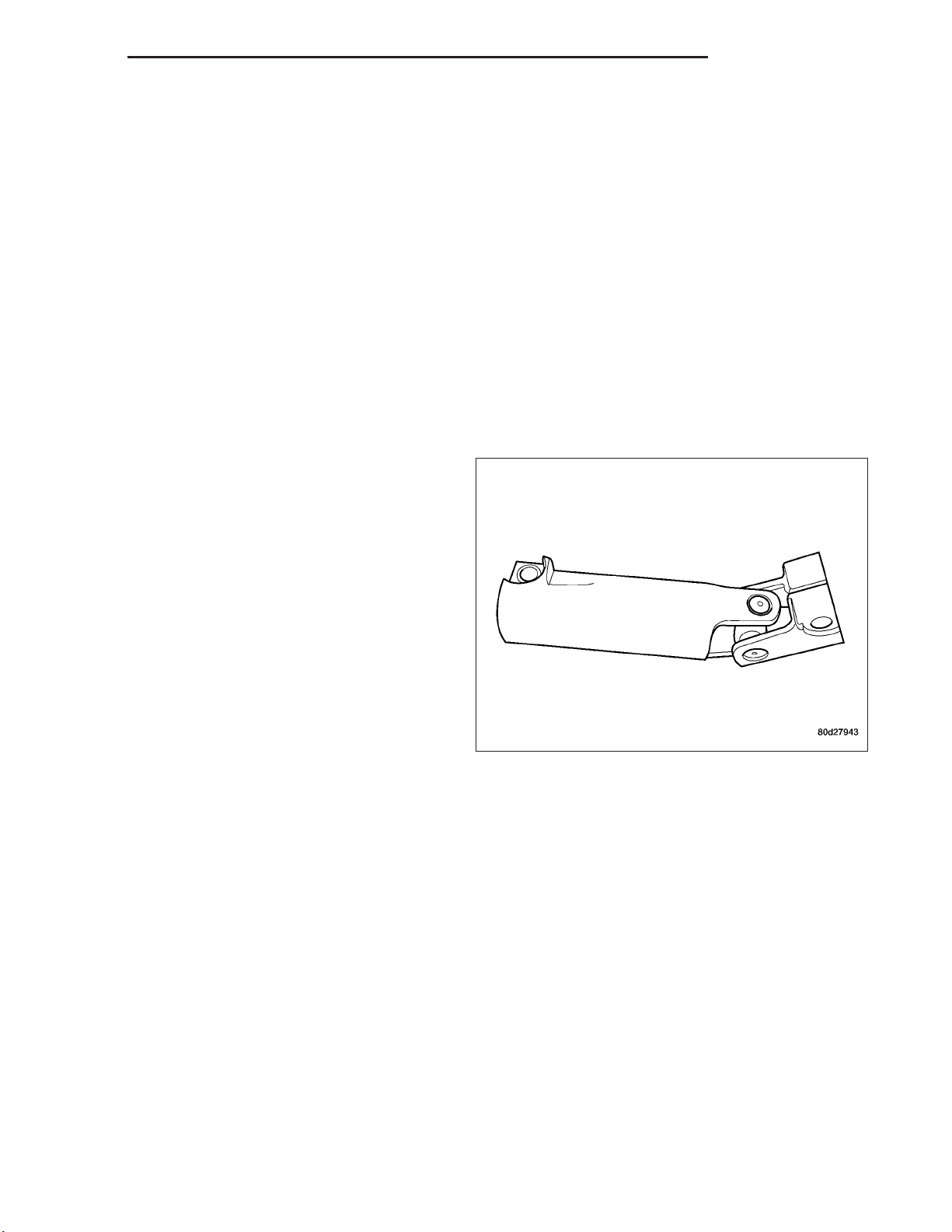
The tilt and standard column (4) has been designed to
be serviced as an assembly; less wiring, switches,
shrouds, steering wheel, etc. Most steering column
components can be serviced without removing the
steering column from the vehicle.
To service the steering wheel, switches or airbag, refer
to Restraints and follow all WARNINGS and
CAUTIONS.
Page 8

19 - 8 COLUMN DR/DH
WARNING: THE AIRBAG SYSTEM IS A SENSITIVE, COMPLEX ELECTRO-MECHANICAL UNIT. BEFORE
ATTEMPTING TO DIAGNOSE, REMOVE OR INSTALL THE AIRBAG SYSTEM COMPONENTS YOU MUST
FIRST DISCONNECT AND ISOLATE THE BATTERY NEGATIVE (GROUND) CABLE. THEN WAIT TWO MINUTES FOR THE SYSTEM CAPACITOR TO DISCHARGE. FAILURE TO DO SO COULD RESULT IN ACCIDENTAL DEPLOYMENT OF THE AIRBAG AND POSSIBLE PERSONAL INJURY. THE FASTENERS, SCREWS, AND
BOLTS, ORIGINALLY USED FOR THE AIRBAG COMPONENTS, HAVE SPECIAL COATINGS AND ARE SPECIFICALLY DESIGNED FOR THE AIRBAG SYSTEM. THEY MUST NEVER BE REPLACED WITH ANY SUBSTITUTES. ANYTIME A NEW FASTENER IS NEEDED, REPLACE WITH THE CORRECT FASTENERS PROVIDED
IN THE SERVICE PACKAGE OR FASTENERS LISTED IN THE PARTS BOOKS.
CAUTION: Do not hammer on steering column shaft. This may cause damage to the shaft or bearing.
CAUTION: Do not attempt to remove the pivot bolts to disassemble the tilting mechanism. Do not remove
shaft lock plate or plate retainer. This will damage the column.
CAUTION: Do not attempt to remove or modify the park lock slider or link.
NOTE: When servicing the steering wheel after removing the old bolt a new bolt must be used when installing.
NOTE: When servicing the coupler a new bolt must be used when installing.
DESCRIPTION - SRT-10
The SRT-10 column has no START position on the key cylinder. The push starter button switch is mounted on the
Instrument panel center stack. All SRT-10 columns are Tilt columns, Standard cab trucks come with manual transmissions, Quad cab trucks come equipped with automatic transmissions.
DIAGNOSIS AND TESTING
STEERING COLUMN
If the vehicle is involved in a front end collision/the air bag has deployed the column must be inspected. This
inspection will determine if the Column has collapsed. Inspect the column mounting capsules visually and manually
push and pull them to check for separation or fractures. If capsules are fractured or have moved the column MUST
be replaced.
REMOVAL
WARNING: BEFORE SERVICING THE STEERING COLUMN THE AIRBAG SYSTEM MUST BE DISARMED.
REFER TO ELECTRICAL RESTRAINT SYSTEM FOR SERVICE PROCEDURES. FAILURE TO DO SO MAY
RESULT IN ACCIDENTAL DEPLOYMENT OF THE AIRBAG AND POSSIBLE PERSONAL INJURY.
CAUTION: All fasteners must be torqued to specification to ensure proper operation of the steering column.
1. Position the front wheels straight ahead.
2. Disconnect the negative (ground) cable from the battery.
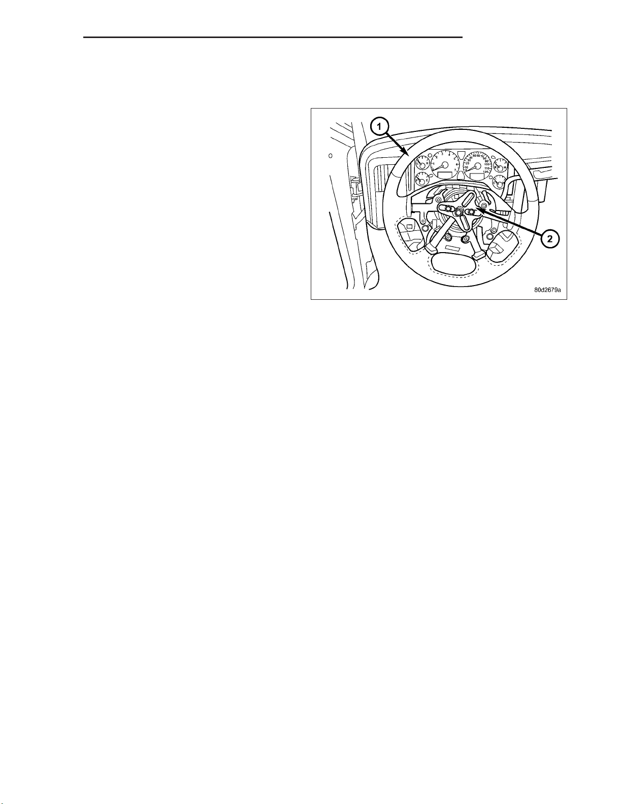
3. Remove the two switches from the steering wheel.
4. Remove the airbag, (Refer to 8 - ELECTRICAL/RESTRAINTS/DRIVER AIRBAG - REMOVAL).
5. Remove the steering wheel with special tool CJ98–1 or an appropriate steering wheel puller.
CAUTION: Ensure the puller bolts are fully engaged into the steering wheel and not into the clockspring,
before attempting to remove the wheel. Failure to do so may damage the steering wheel/clockspring.
Page 9
DR/DH COLUMN 19 - 9
6. Remove the steering column opening cover (Refer to 23 - BODY/INSTRUMENT PANEL/STEERING COLUMN
OPENING COVER - REMOVAL).
7. Remove the tilt lever.
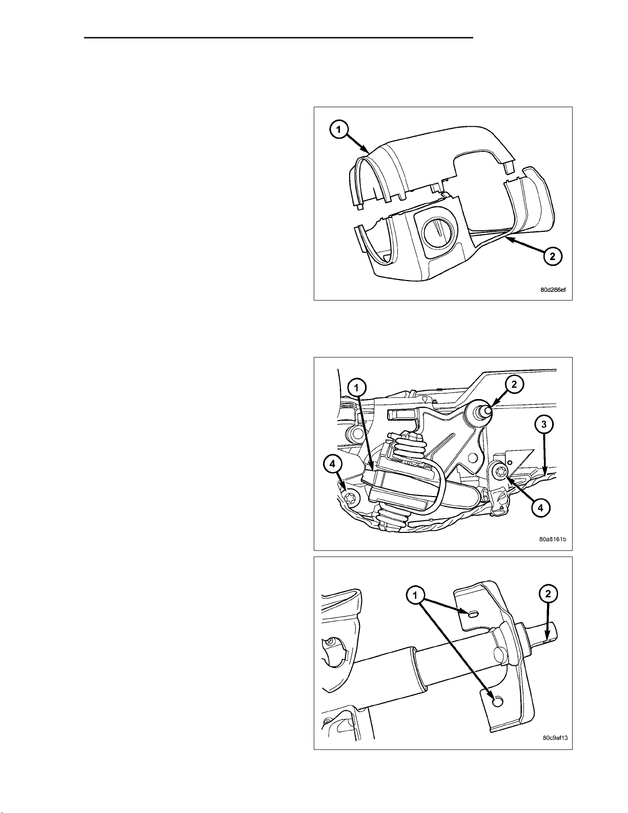
8. Remove the column shrouds (1&2).
9. Remove the clock spring, (Refer to 8 - ELECTRICAL/RESTRAINTS/CLOCKSPRING - REMOVAL).
10. Disconnect the wiring harness to the column.
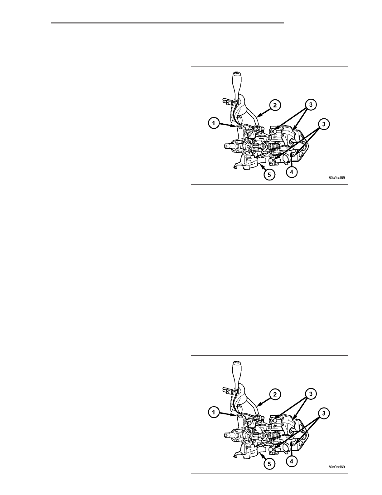
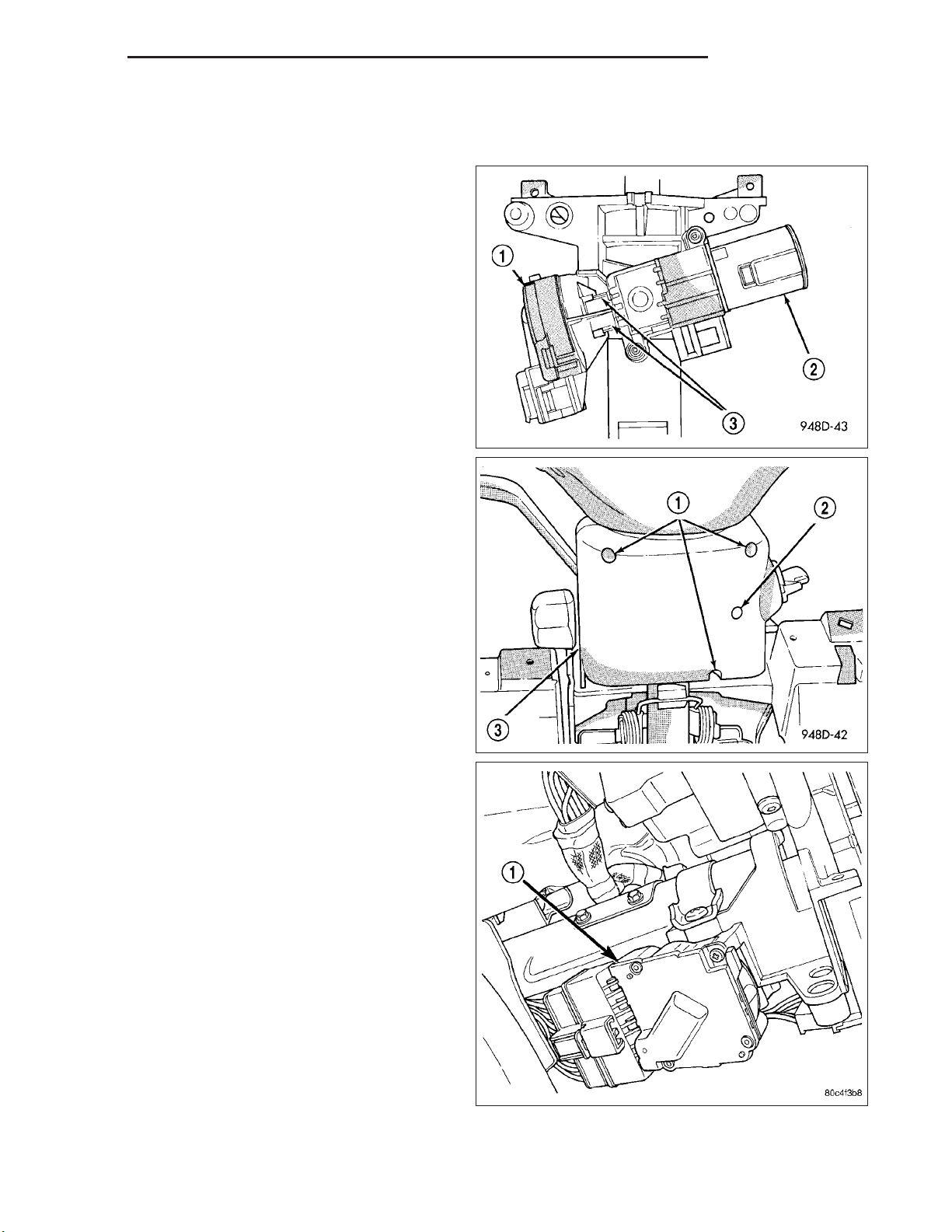
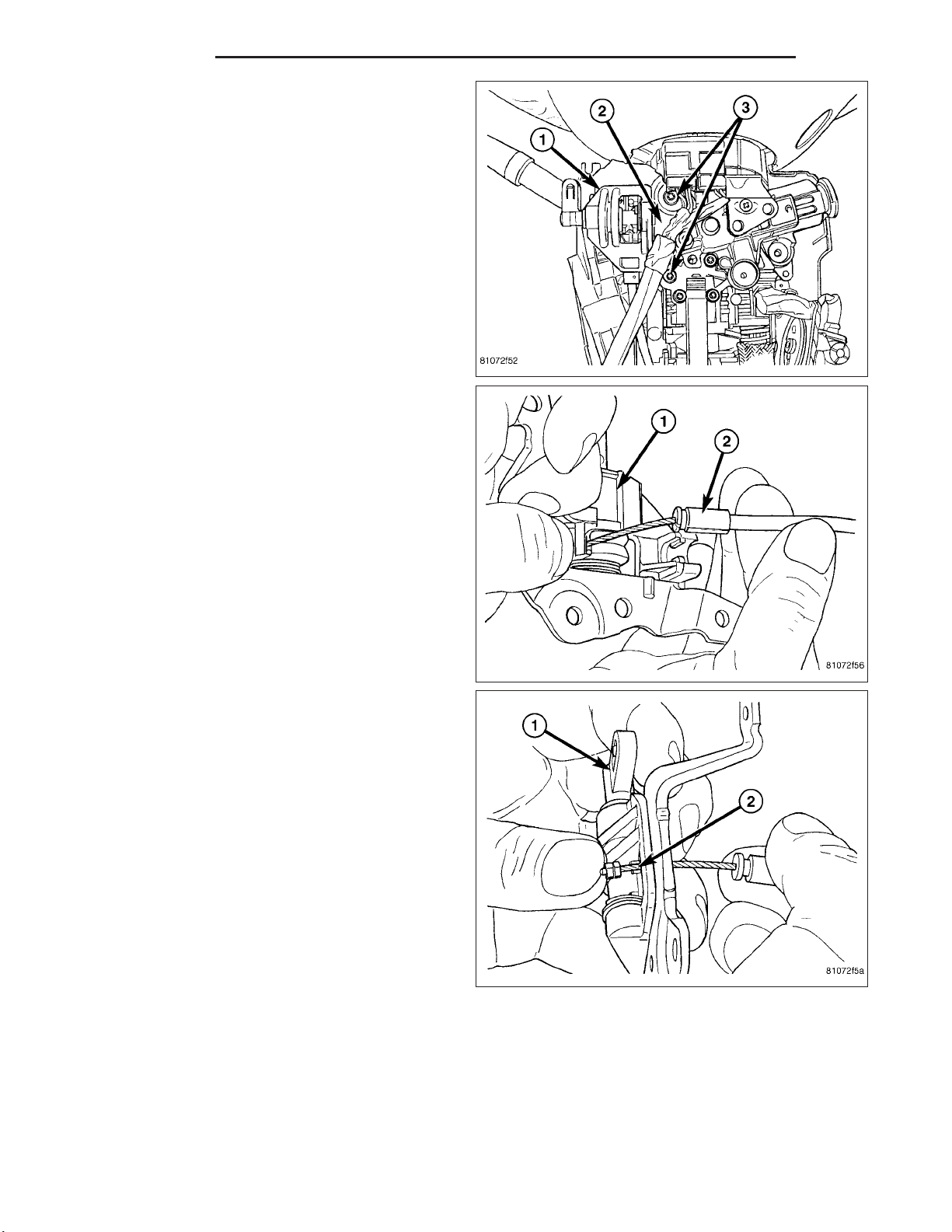
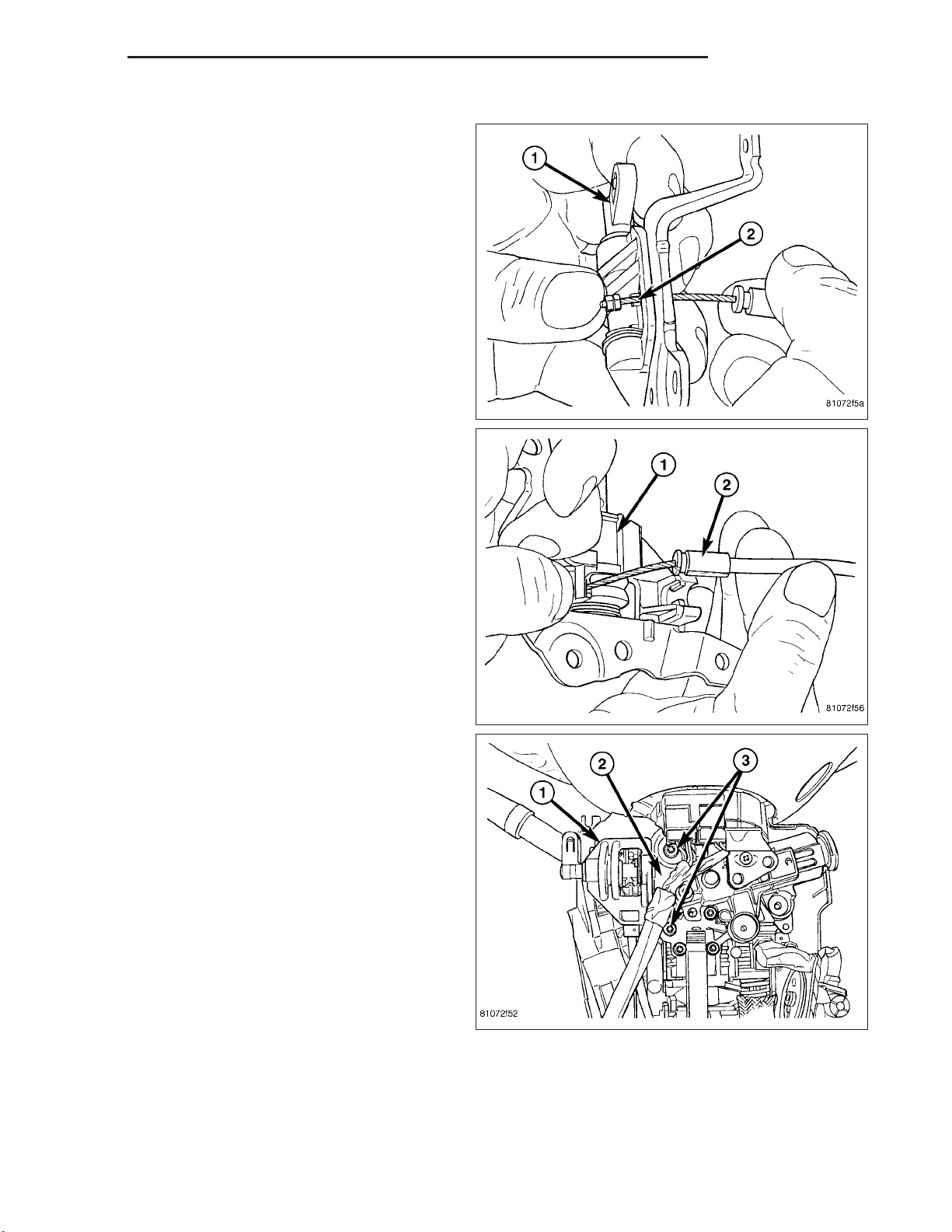
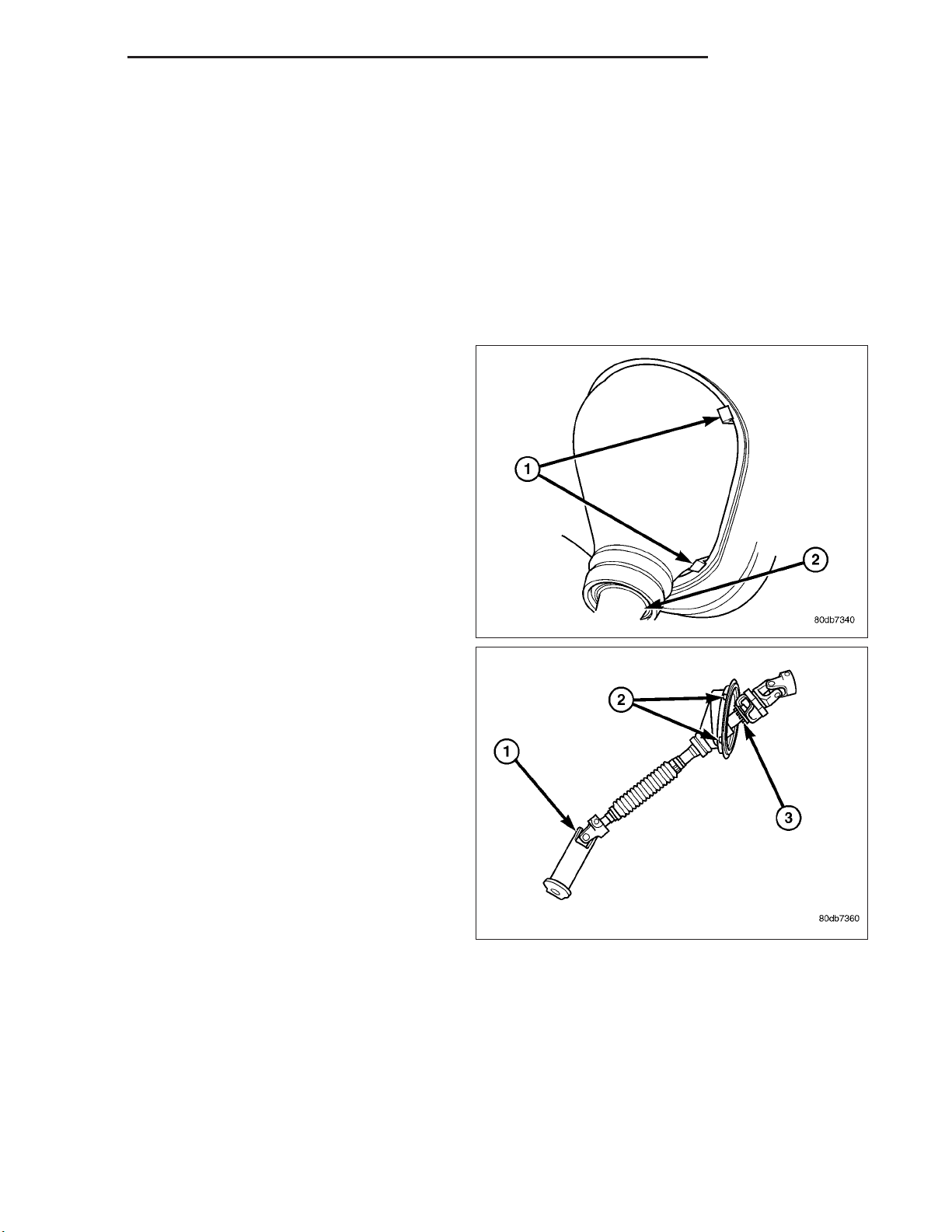
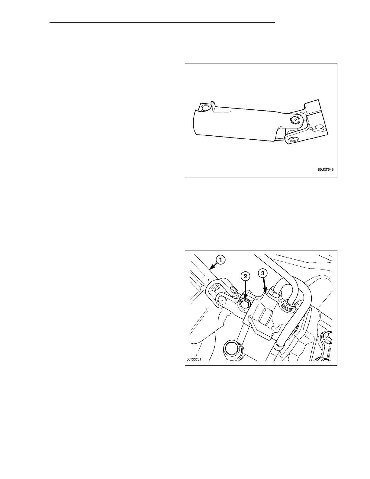
11. Remove the shift cable(2) from the column shift
lever actuator (1) (Refer to 21 - TRANSMISSION/
TRANSAXLE/AUTOMATIC - 32RH/GEAR SHIFT
CABLE - REMOVAL)..
12. Release the shift cable from the column bracket
and remove it from the bracket.
13. Remove the SKIM module in order to disconnect
the electrical connector.
14. Remove the upper steering shaft coupler bolt (2)..
Page 10
19 - 10 COLUMN DR/DH
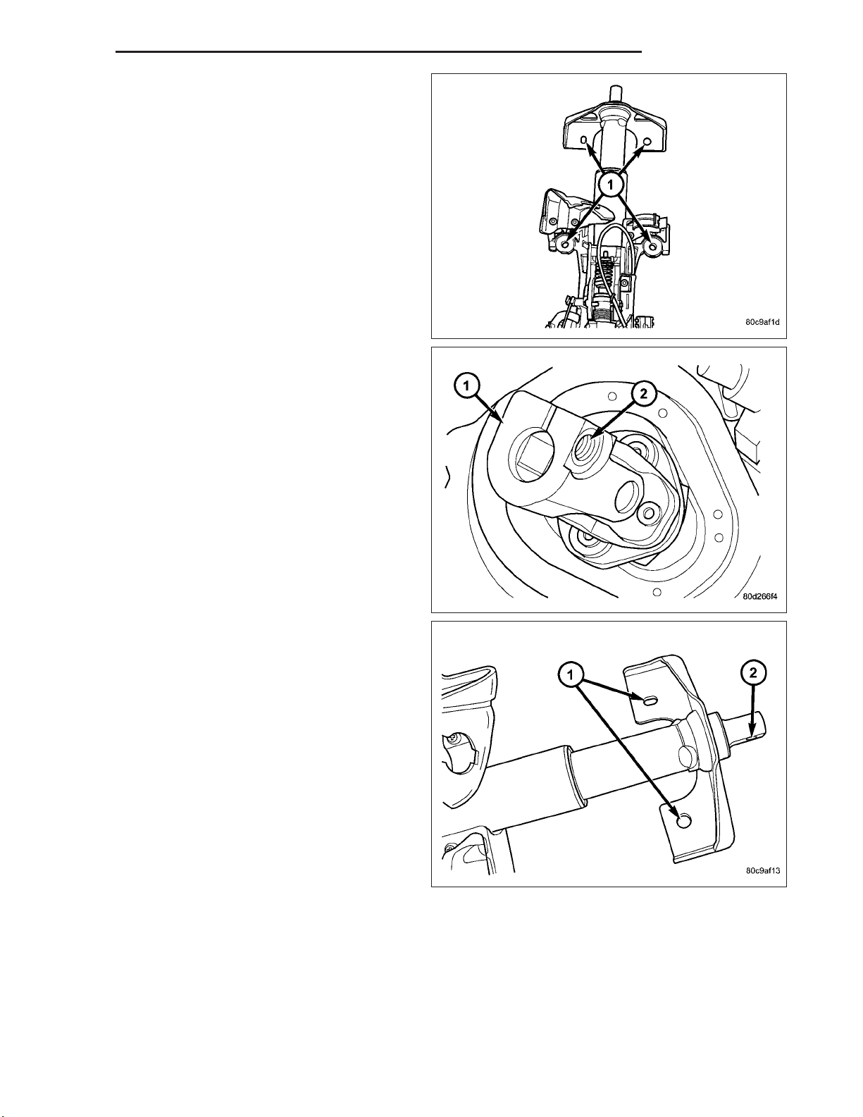
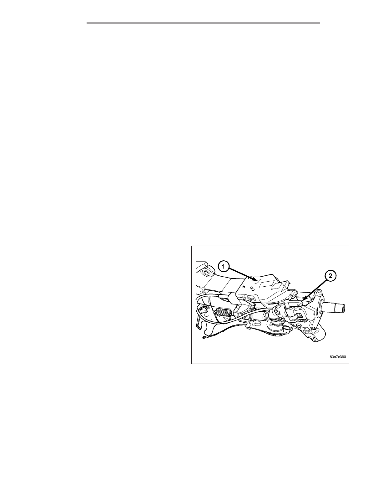
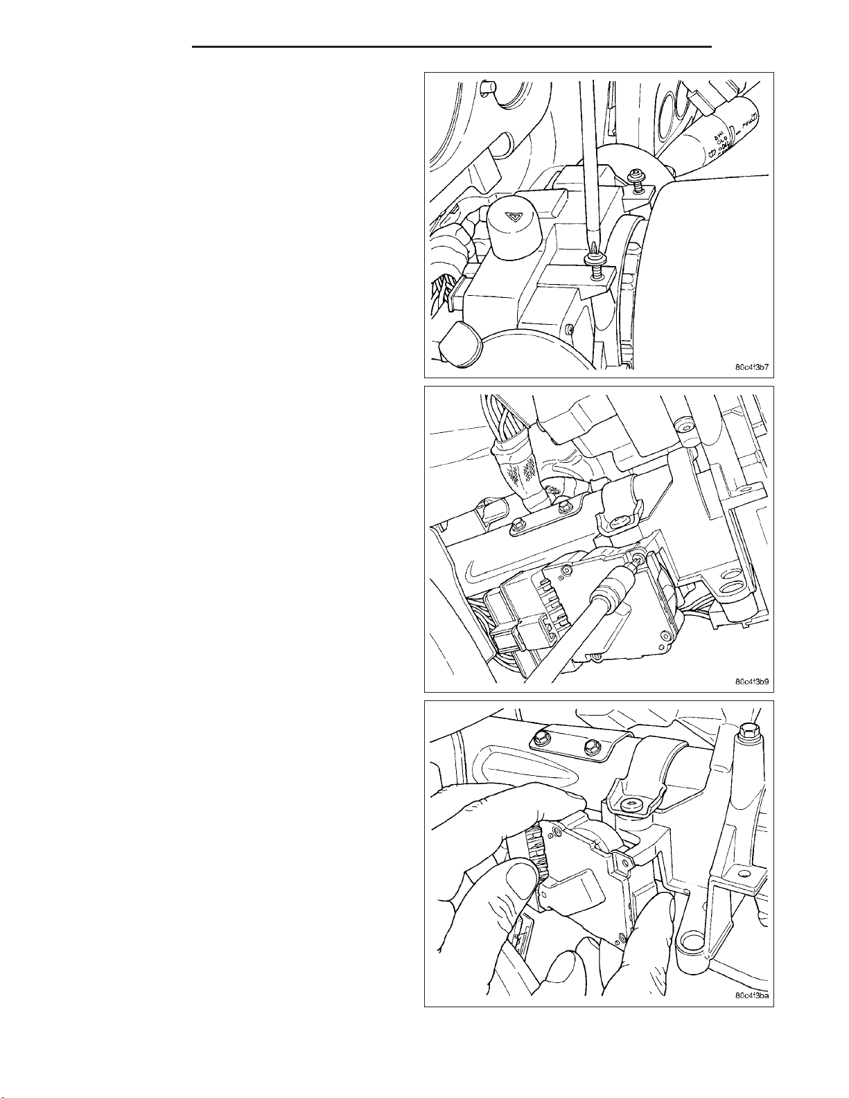
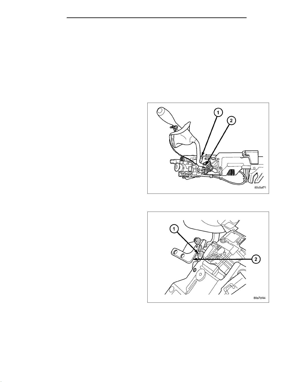
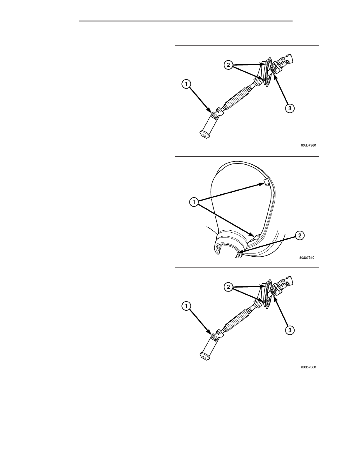
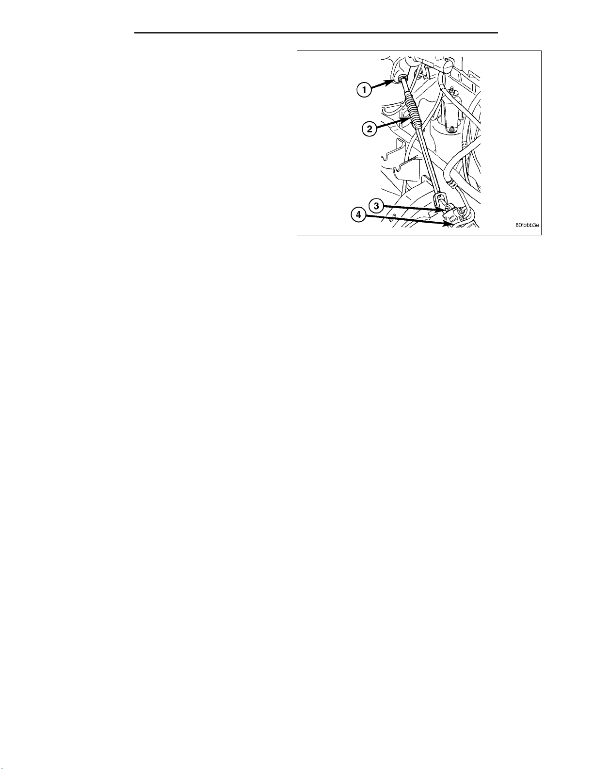
15. Seperate the shaft from the coupler (1).
16. Remove the brake light switch and discard (Refer
to 8 - ELECTRICAL/LAMPS/LIGHTING - EXTERIOR/BRAKE LAMP SWITCH - REMOVAL).
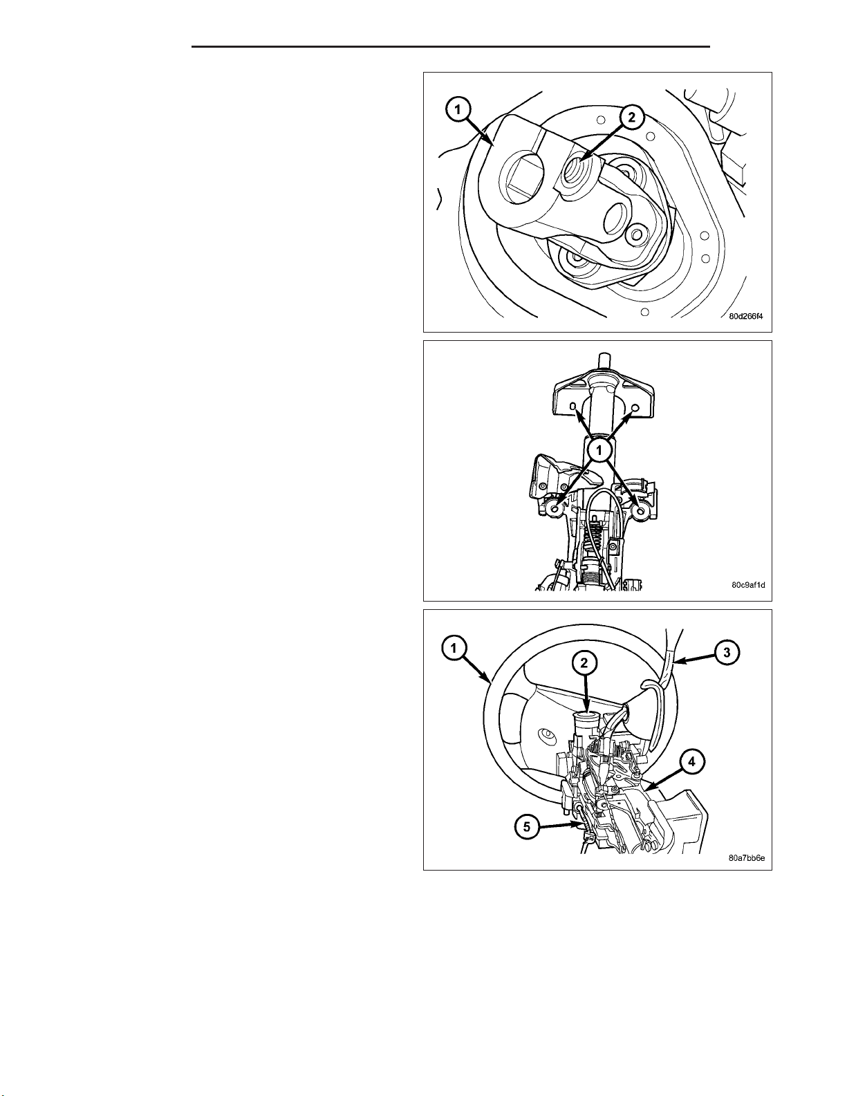
17. Remove the four steering column mounting nuts
(1).
18. Remove the steering column assembly (4) from
the vehicle..
INSTALLATION
WARNING: BEFORE SERVICING THE STEERING COLUMN THE AIRBAG SYSTEM MUST BE DISARMED.
REFER TO ELECTRICAL RESTRAINT SYSTEM FOR SERVICE PROCEDURES. FAILURE TO DO SO MAY
RESULT IN ACCIDENTAL DEPLOYMENT OF THE AIRBAG AND POSSIBLE PERSONAL INJURY.
CAUTION: All fasteners must be torqued to specification to ensure proper operation of the steering column.
Page 11
DR/DH COLUMN 19 - 11
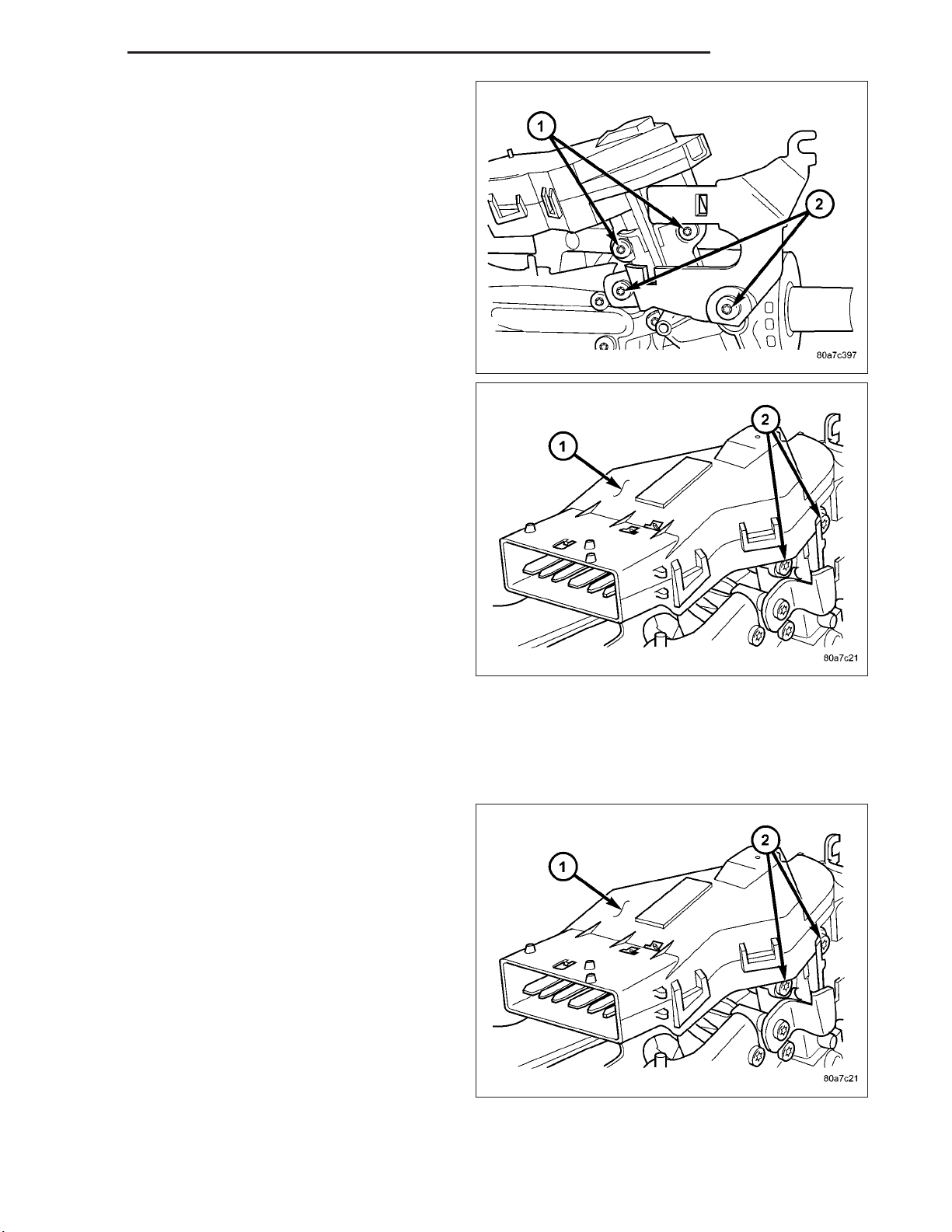
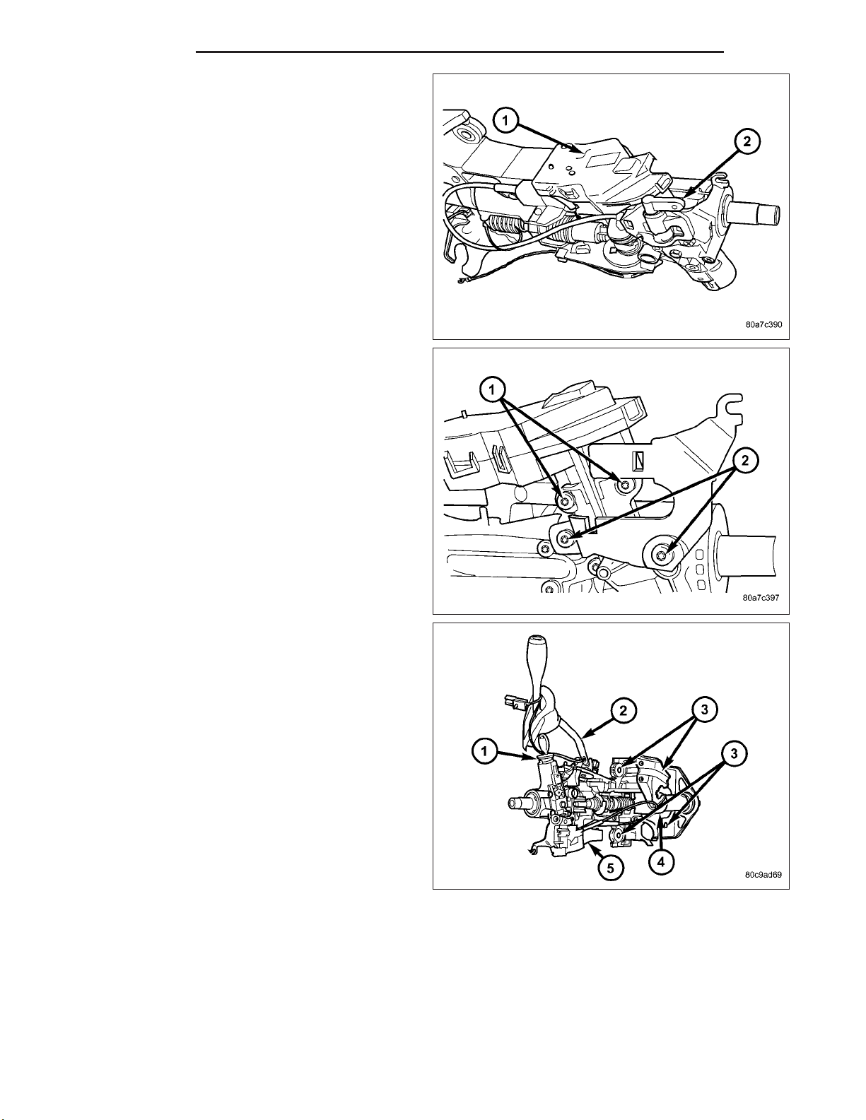
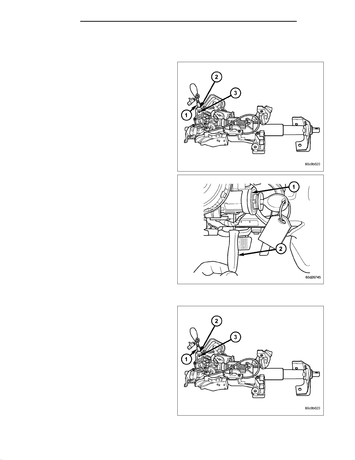
1. Position the steering column on the dash panel
support and loosely install the mounting nuts (1).
2. Firmly slide the steering column upward against the
studs in dash panel and hand tighten the nuts.
3. Install the steering shaft coupler (1) on the steering
shaft and loosely install a new bolt.
4. Center steering column in dash opening and
tighten mounting nuts (1) to 28 N·m (250 in. lbs.).
NOTE: Torque the upper left nut first then the
lower right nut. Then torque the lower left nut then
the upper right nut.
NOTE: A new bolt must be used for reinstallation.
5. Tighten the coupler bolt (2) to 57 N·m (42 ft. lbs.).
Page 12
19 - 12 COLUMN DR/DH
6. Install a new brake light switch (Refer to 8 - ELECTRICAL/LAMPS/LIGHTING - EXTERIOR/BRAKE
LAMP SWITCH - REMOVAL).
7. Install the shifter cable (2). (Refer to 21 - TRANSMISSION/TRANSAXLE/AUTOMATIC - 32RH/GEAR
SHIFT CABLE - INSTALLATION)
8. Connect the wiring harness to the column.
9. Install the SKIM module.
10. Install the clockspring (Refer to 8 - ELECTRICAL/
RESTRAINTS/CLOCKSPRING - REMOVAL).
11. Install the shrouds (1&2).
12. Install the steering column opening cover (Refer
to 23 - BODY/INSTRUMENT PANEL/STEERING
COLUMN OPENING COVER - INSTALLATION).
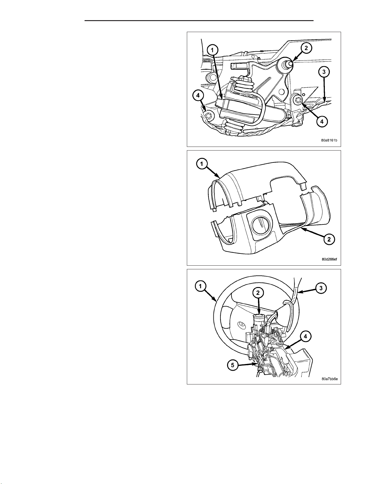
13. Align the spline on the wheel hub to shaft.
14. Then install the steering wheel (1) and install a
new bolt. Tighten the bolt to 61 N·m (45 ft. lbs.).
15. Install the airbag (Refer to 8 - ELECTRICAL/RE-
STRAINTS/DRIVER AIRBAG - INSTALLATION).
16. Install the two steering wheel switches.
17. Install the tilt lever handle.
18. Install the negative battery terminal.
19. Test the operation of the horn, Electronic PRNDL
Indicator, lights and any other functions that are
steering column operated.
Page 13
DR/DH COLUMN 19 - 13
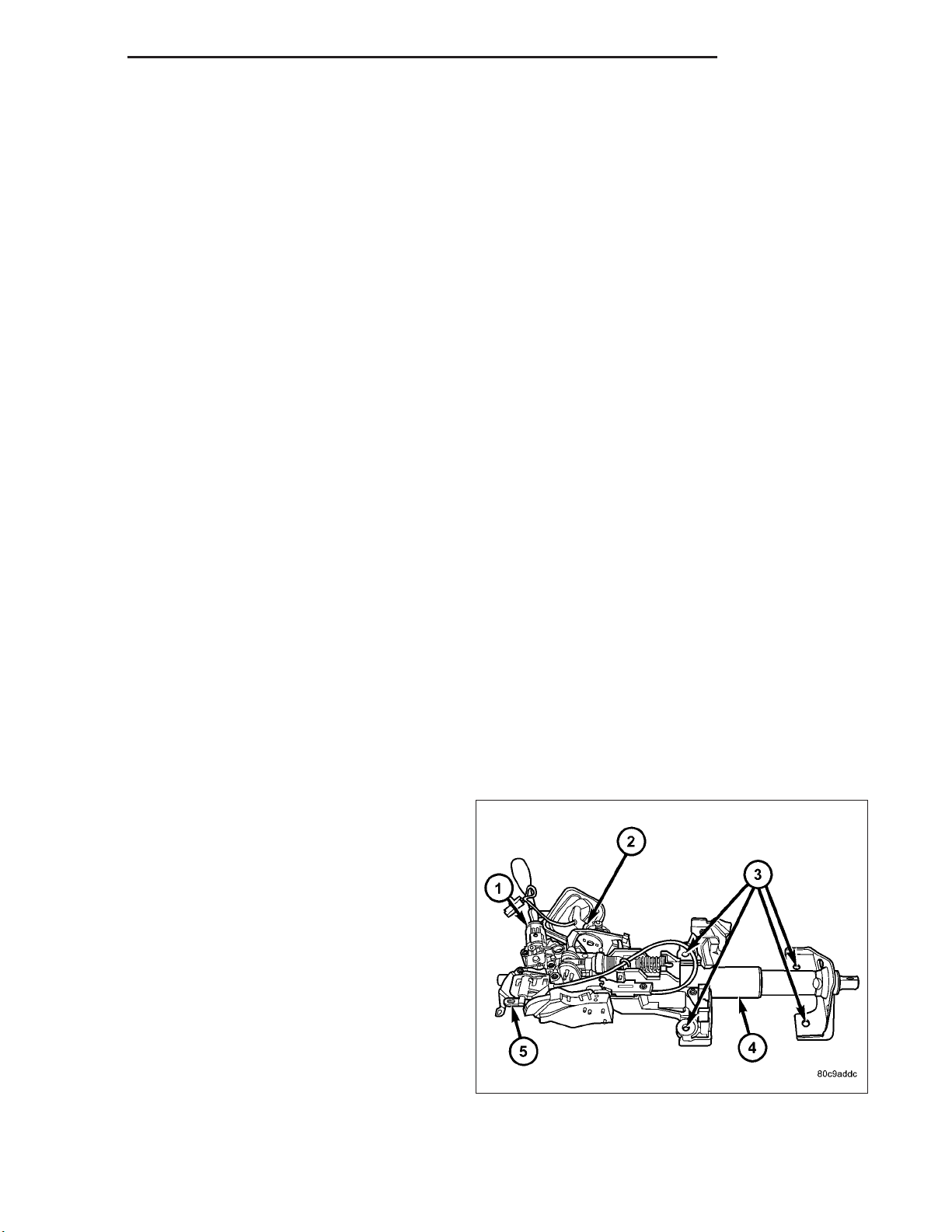
IGNITION SWITCH
DESCRIPTION
The ignition switch (5) is located on the steering column (4). It is used as the main on/off switching device
for most electrical components. The mechanical key
cylinder is used to engage/disengage the electrical
ignition switch.
OPERATION
Vehicles equipped with an automatic transmission and a steering column mounted shifter: an interlock
device is located within the shift cable. This interlock device is used to lock the transmission shifter in the PARK
position when the key cylinder is in any position and the brake pedal is not depressed.
DIAGNOSIS AND TESTING
IGNITION SWITCH
TEST AND REPAIR
If the key removal effort is excessive on a vehicle with a automatic transmission first adjust the shift linkage, (Refer
to 21 - TRANSMISSION/TRANSAXLE/AUTOMATIC - 46RE/GEAR SHIFT CABLE - ADJUSTMENTS).
If the ignition switch effort is excessive remove the ignition key cylinder from the steering column. (Refer to 19 STEERING/COLUMN/LOCK CYLINDER HOUSING - REMOVAL). Check the turning effort of the key cylinder. If the
ignition key cylinder effort is excessive replace the key cylinder.
REMOVAL
SERVICE PRECAUTIONS
NOTE: The steering column on vehicles equipped
with an automatic transmission is not equipped
with an internal locking shaft with the ignition cylinder. Alternative methods of locking the steering
wheel for service will have to be used.
The tilt and standard column (4) have been designed
to be serviced as an assembly; without wiring,
switches, shrouds, steering wheel, etc. Most steering
column components can be serviced without removing
the steering column from the vehicle.
Safety goggles should be worn at all times when
working on steering columns.
Page 14
19 - 14 COLUMN DR/DH
To service the steering wheel, switches or airbag, Refer to Electrical Restraints and follow all WARNINGS and CAUTIONS.
WARNING: THE AIRBAG SYSTEM IS A SENSITIVE, COMPLEX ELECTRO-MECHANICAL UNIT. BEFORE
ATTEMPTING TO DIAGNOSE, REMOVE OR INSTALL THE AIRBAG SYSTEM COMPONENTS YOU MUST
FIRST DISCONNECT AND ISOLATE THE BATTERY NEGATIVE (GROUND) CABLE. THEN WAIT TWO MINUTES FOR THE SYSTEM CAPACITOR TO DISCHARGE. FAILURE TO DO SO COULD RESULT IN ACCIDENTAL DEPLOYMENT OF THE AIRBAG AND POSSIBLE PERSONAL INJURY. THE FASTENERS, SCREWS, AND
BOLTS, ORIGINALLY USED FOR THE AIRBAG COMPONENTS, HAVE SPECIAL COATINGS AND ARE SPECIFICALLY DESIGNED FOR THE AIRBAG SYSTEM. THEY MUST NEVER BE REPLACED WITH ANY SUBSTITUTES. ANYTIME A NEW FASTENER IS NEEDED, REPLACE WITH THE CORRECT FASTENERS PROVIDED
IN THE SERVICE PACKAGE OR FASTENERS LISTED IN THE PARTS BOOKS.
CAUTION: Do not hammer on steering column shaft. This may cause damage to the shaft or bearing.
CAUTION: Do not attempt to remove the pivot bolts to disassemble the tilting mechanism.
The ignition key must be in the key cylinder for cylinder removal. The key cylinder must be removed first before
removing ignition switch.
1. Remove the negative (ground) cable from the battery.
2. Disable the airbag, (Refer to 8 - ELECTRICAL/RESTRAINTS/DRIVER AIRBAG - REMOVAL).
3. Remove the lower and upper shrouds.
4. Remove key cylinder. (Refer to 19 - STEERING/COLUMN/LOCK CYLINDER HOUSING - REMOVAL).
5. Disconnect the lower clockspring connectors.
6. Remove the wire retainer from the tilt lever bracket.
7. Remove the tilt lever mounting screws to gain
access to the ignition switch (1) mounting screws.
Page 15
DR/DH COLUMN 19 - 15
8. For columns without tilt remove the bracket (2) to
gain access to the ignition switch mounting screws
(2).
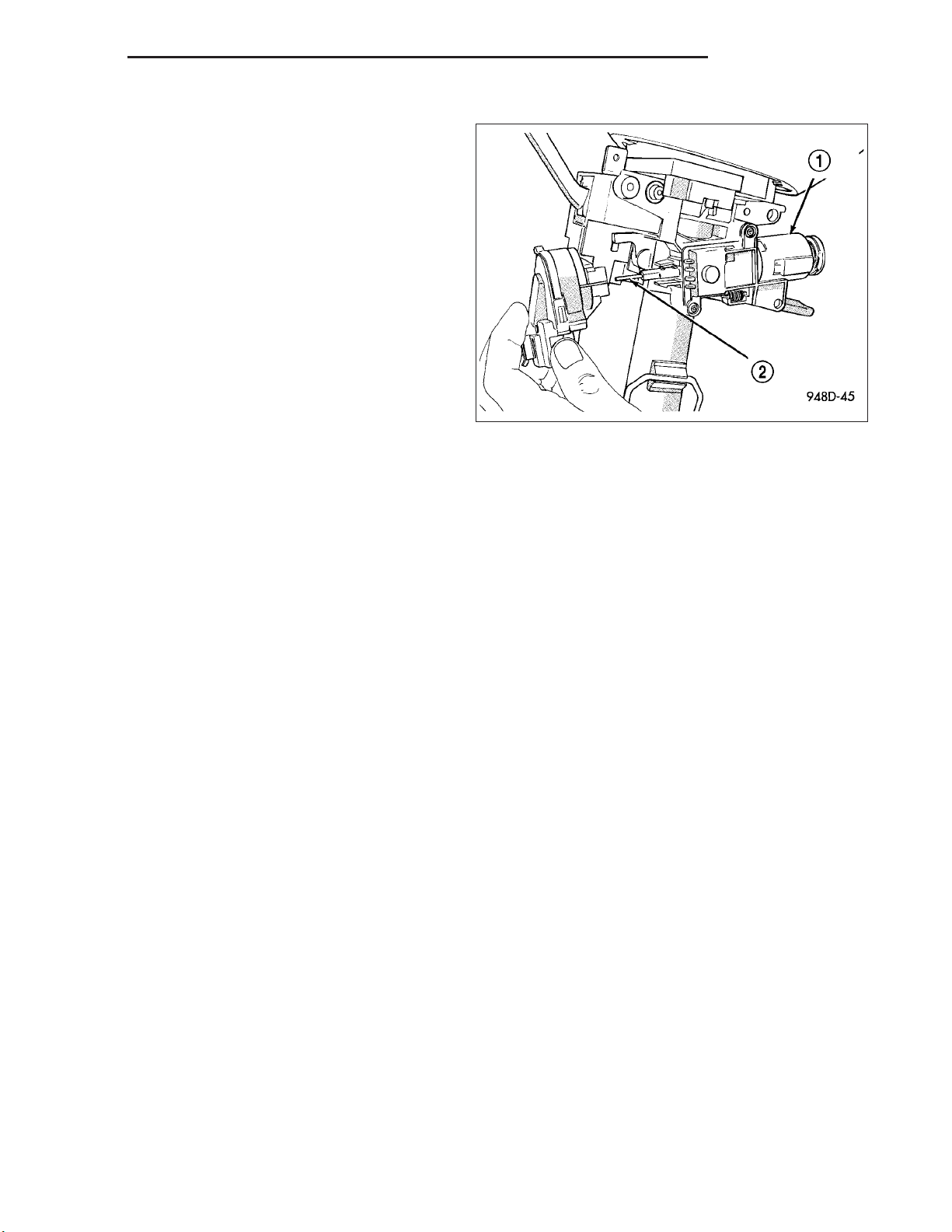
9. Disconnect the electrical connector at rear of ignition switch (1).
10. Remove ignition switch mounting screw (2).
11. Using a small screwdriver, push on locking tab
and remove switch from steering column.
INSTALLATION
The ignition key must be in the key cylinder for cylinder removal. The key cylinder must be removed first before
installing ignition switch.
1. Before installing ignition switch, rotate the slot in the switch to the ON position.
2. Connect the electrical connector to rear of the ignition switch. Make sure that locking tabs are fully
seated into wiring connector.
3. Position switch (1) to column and install the mounting screw (2). Tighten screw to 3 N·m (26 in. lbs.).
Page 16
19 - 16 COLUMN DR/DH
4. Install the tilt lever bracket (2) mounting screws.
Tighten screws to 4.5 N·m (40 in. lbs.).
5. If the column is non-tilt install the bracket (2).
Tighten screws to 4.5 N·m (40 in. lbs.)
6. Position the wire retainer into the tilt lever bracket.
7. Reconnect the lower clockspring connectors.
8. Install the key cylinder (1)
9. Install steering column upper and lower shrouds.
10. Enable the airbag system. (Refer to 8 - ELECTRI-
CAL/RESTRAINTS/DRIVER AIRBAG INSTALLATION).
Page 17
DR/DH COLUMN 19 - 17
IGNITION SWITCH - SRT-10
REMOVAL - SRT-10
The ignition switch (1) attaches to the lock cylinder
housing (2) on the end opposite the lock cylinder. For
ignition switch terminal and circuit identification, refer
to the Wiring Diagrams sections.
1. Disconnect negative cable from battery.
2. Place key cylinder in RUN position. Through the
hole in the lower shroud (2), depress lock cylinder
retaining tab and remove key cylinder.
3. Remove upper and lower shrouds (3) from steering
column.
4. Disconnect electrical connectors from ignition
switch (1).
Page 18
19 - 18 COLUMN DR/DH
5. Remove the 2 screws on the top of the multi-function switch and relocate.
6. Remove ignition switch mounting screw with a #10
TorxT bit.
7. Pull ignition switch from steering column.
Page 19
DR/DH COLUMN 19 - 19
INSTALLATION - SRT-10
1. Ensure the ignition switch is in the RUN position
and the actuator shaft (2) in the lock housing (1) is
in the RUN position.
2. Carefully install the ignition switch. The switch will
snap over the retaining tabs. Install mounting
screw.
3. Install electrical connectors to ignition switch.
4. Install the multi-function switch and tighten the 2
screws.
5. Install upper and lower shrouds.
6. Install key cylinder (cylinder retaining tab will depress only in the RUN position).
7. Connect negative cable to battery.
8. Check for proper operation of ignition switch and key-in warning switch.
KEY-IN IGNITION SWITCH
DESCRIPTION
The key-in ignition switch is integral to the ignition switch, which is mounted on the left side of the steering column.
It closes a path to ground for the Central Timer Module (CTM) when the ignition key is inserted in the ignition key
cylinder and the driver door ajar switch is closed (driver door is open). The key-in ignition switch opens the ground
path when the key is removed from the ignition key cylinder. The ground path is also opened when the driver door
ajar switch is open (driver door is closed).
The key-in ignition switch cannot be repaired and, if faulty or damaged, the entire ignition switch must be replaced,
(Refer to 19 - STEERING/COLUMN/IGNITION SWITCH - REMOVAL).
DIAGNOSIS AND TESTING
IGNITION SWITCH AND KEY LOCK CYLINDER
ELECTRICAL DIAGNOSIS
For ignition switch electrical schematics, refer to Ignition Switch in the appropriate section of Electrical Wiring Diagrams.
MECHANICAL DIAGNOSIS (KEY DIFFICULT TO ROTATE)
(Refer to 19 - STEERING/COLUMN/IGNITION SWITCH - DIAGNOSIS AND TESTING).
Page 20
19 - 20 COLUMN DR/DH
KEY CYLINDER
REMOVAL
The ignition key (1) must be in the key cylinder (2) for
cylinder removal.
1. Disconnect negative cable from battery.
2. Remove upper and lower covers (shrouds) from
steering column.
3. Place shifter in PARK position.
4. A retaining pin is located at side of key cylinder
assembly (2).
a. Rotate key to RUN position.
b. Press in on retaining pin while pulling key cyl-
inder (1) from ignition switch.
INSTALLATION
The ignition key (1) must be in the key cylinder (2) for
cylinder installation.
1. Install the key cylinder into the housing using care
to align the end of the key cylinder (2) with the ignition switch.
2. Push the key cylinder (2) in until it clicks.
3. Replace the upper and lower shrouds.
4. Reconnect the battery.
Page 21
DR/DH COLUMN 19 - 21
STEERING WHEEL
REMOVAL
1. Disable and remove the driver’s side airbag. (Refer
to 8 - ELECTRICAL/RESTRAINTS/DRIVER AIRBAG - REMOVAL).
2. Partially remove the steering wheel bolt (1) and
leave the bolt in the column.
3. Install puller CJ98-1 (2) or equivalent using the top
of the bolt to push on.
4. Remove and discard the steering wheel bolt.
5. Remove the steering wheel (1).
INSTALLATION
NOTE: Do not reuse the old steering wheel bolt (a new bolt must be used)
1. Install steering wheel to the column
NOTE: Be certain that the steering wheel mounting bolt is tightened to the proper torque specification to
ensure proper clockspring operation.
2. Install the new steering wheel bolt. Tighten the bolt to 61 N·m (45 ft. lbs.).
3. Install the driver’s side air bag. (Refer to 8 - ELECTRICAL/RESTRAINTS/DRIVER AIRBAG - INSTALLATION).
TILT LEVER KNOB RELEASE
REMOVAL
1. Remove the tilt lever handle.
2. Remove the steering column opening cover (Refer to 23 - BODY/INSTRUMENT PANEL/STEERING COLUMN
OPENING COVER - REMOVAL).
3. Remove the lower shroud.
NOTE: Use special care not to pry on the clockspring electrical connector when removing or installing the
mounting screw located next to the clockspring.
Page 22
19 - 22 COLUMN DR/DH
4. Remove the two mounting screws (3) from the tilt
lever knob release bracket (1).
5. Disconnect the electrical harness plastic mounting
tab (2) from the the bracket (1).
6. Unsnap the cable (2) from the bracket (1).
7. Remove the end of the cable (2) from the tilt lever
knob release bracket (1).
Page 23
DR/DH COLUMN 19 - 23
INSTALLATION
1. Route the cable (2) into the tilt lever release knob
bracket (1).
2. Snap the cable end (2) into the bracket (1).
NOTE: Use special care not to pry on the clockspring electrical connector when removing or
installing the mounting screw located next to the
clockspring.
NOTE: New screws should be used when installing the tilt lever release knob bracket to the column.
3. Install the tilt lever release knob bracket (1) to the
column and install the two new mounting screws
(3) Tighten the two new screws to 4.5 N·m (40 in.
lbs.).
4. Install the electrical harness plastic mounting tab
(2) to the bracket (1).
5. Install the lower shroud.
6. Install the steering column opening cover (Refer to 23 - BODY/INSTRUMENT PANEL/STEERING COLUMN
OPENING COVER - INSTALLATION).
7. Install the tilt lever handle.
Page 24
19 - 24 COLUMN DR/DH
GEAR SHIFT LEVER
REMOVAL
1. Remove the kneeblocker. (Refer to 23 - BODY/INSTRUMENT PANEL/KNEE BLOCKER - REMOVAL).
2. Remove the upper and lower column shroud.
3. Remove and discard the brake light switch.
4. Loosen the column bolts and lower the column enough to allow clearance for the gear shift lever removal.
5. Disconnect the overdrive switch harness (if equipped).
6. Disconnect the shift cable from the shift lever.
7. Remove the SKIM.
8. Remove the gear shift lever mounting screws and
remove the lever (2).
9. Remove the blocker pin from the inhibit link slot
(1).
INSTALLATION
1. Install the lever assembly (2) using care to install
the pin in the blocker to slider slot (1) and install
the mounting screws and tighten to 12 N·m (105 in.
lbs.).
2. Cycle the key from ACC to RUN and ensure that
the blocker does not stick or bind.
3. Turn the key to the OFF position and ensure that
the shifter will not pull from the PARK position.
4. Connect the over drive switch harness (if
equipped).
NOTE: Route and tie off harness to original location.
5. Connect the shift cable to the lever (2).
6. Ensure the gear shift lever and transmission are in the PARK position and snap the cable adjust clip in place.
7. Install a new brake light switch (Refer to 8 - ELECTRICAL/LAMPS/LIGHTING - EXTERIOR/BRAKE LAMP
SWITCH - INSTALLATION).
8. Install the SKIM and halo.
9. Install the upper and lower column shroud.
10. Install the column back into place and tighten.
11. Install the kneeblocker. (Refer to 23 - BODY/INSTRUMENT PANEL/KNEE BLOCKER - INSTALLATION).
Page 25
DR/DH COLUMN 19 - 25
UPPER STEERING COUPLING
REMOVAL
1. Disconnect the negative battery cable.
NOTE: The steering column on vehicles with an automatic transmission may not be equipped with an internal locking shaft that allows the ignition key cylinder to be locked with the key. Alternative methods of locking the steering wheel for service will have to be used.
2. Lock the steering wheel with the tire in the straight position.
3. Remove and discard the lower pinch bolt.
4. Lower the steering coupler shaft from the column.
5. Remove the upper steering coupling shaft (2) seal
by pushing in the four tags (1) securing it to the
panel.
6. Remove and discard the lower coupler pinch bolt
(1) from the lower steering coupling shaft (1).
7. Remove the upper steering coupling shaft (3) from
the vehicle.
Page 26
19 - 26 COLUMN DR/DH
INSTALLATION
1. Install the upper steering coupling shaft (3) to the
vehicle.
2. Install the upper steering coupling shaft seal (2) by
pushing it in securing the four tangs (1) to the
panel.
NOTE: Note: A new steering coupling shaft pinch
bolt for the upper and lower shafts must be used.
3. Install the steering coupler shaft (1) to the column.
4. Install the upper pinch bolt (3) use new bolt and
tighten to 57 N.m (42 ft.lbs).
5. Install the shaft to the lower coupler (1).
6. Install the lower pinch bolt (1) use new bolt and
tighten to 57 N.m (42 ft.lbs).
7. Unlock the steering wheel.
8. Reconnect the negative battery cable.
Page 27
DR/DH COLUMN 19 - 27
LOWER STEERING COUPLING
REMOVAL
ALL LD & HD EXCEPT 4X4 HD
1. Disconnect the negative battery cable.
2. Raise and support the vehicle.
NOTE: The steering column on vehicles with an automatic transmission may not be equipped with an internal locking shaft that allows the ignition key cylinder to be locked with the key. Alternative methods of locking the steering wheel for service will have to be used.
3. Lock the steering wheel with the tire in the straight position.
4. Remove the left front tire and wheel assembly.
5. Mark both coupler connections for proper installation.
6. Remove and discard the upper coupler pinch bolt.
7. Remove and discard the lower coupler pinch bolt.
8. Remove the lower steering shaft coupler.
4X4 HD
1. Disconnect the negative battery cable.
2. Raise and support the vehicle.
NOTE: The steering column on vehicles with an automatic transmission may not be equipped with an internal locking shaft that allows the ignition key cylinder to be locked with the key. Alternative methods of locking the steering wheel for service will have to be used.
3. Lock the steering wheel with the tire in the straight position.
4. Remove the left front tire and wheel assembly.
Page 28
19 - 28 COLUMN DR/DH
5. Remove and discard the upper coupler pinch bolt
(1).
6. Remove and discard the lower coupler pinch bolt
(2).
7. Remove the lower steering shaft coupler (3).
Page 29
DR/DH COLUMN 19 - 29
INSTALLATION
ALL LD & HD EXCEPT 4X4 HD
1. Install the coupler to the steering rack & pinion
using the marks made in the removal process.
2. Install the coupler to the intermediate shaft using
the marks made in the removal process.
NOTE: New pinch bolts must be used for reinstallation.
3. Install the lower pinch bolt and tighten to 57 N·m
(42 ft. lbs.).
4. Install the upper pinch bolt and tighten to 57 N·m
(42 ft. lbs.).
5. Install the left front tire and wheel assembly (Refer to 22 - TIRES/WHEELS/WHEELS - STANDARD PROCEDURE).
6. Lower the vehicle.
7. Reconnect the negative battery cable.
8. Unlock the steering wheel.
4X4 HD
1. Install the coupler (2) to the steering gear (3).
Page 30
19 - 30 COLUMN DR/DH
2. Install the coupler (3) to the intermediate shaft (2).
NOTE: New pinch bolts must be used for reinstallation.
3. Install the lower pinch bolt (3) and tighten to 28
N·m (250 in. lbs.).
4. Install the upper pinch bolt (1) and tighten to 57
N·m (42 ft. lbs.).
5. Install the left front tire and wheel assembly (Refer to 22 - TIRES/WHEELS/WHEELS - STANDARD PROCEDURE).
6. Lower the vehicle.
7. Reconnect the negative battery cable.
8. Unlock the steering wheel.
Page 31

DR/DH GEAR - INDEPENDENT FRONT SUSPENSION 19 - 31
GEAR - INDEPENDENT FRONT SUSPENSION
TABLE OF CONTENTS
page page
GEAR - INDEPENDENT FRONT SUSPENSION
DESCRIPTION .........................31
REMOVAL .............................31
INSTALLATION .........................32
SPECIFICATIONS
TORQUE CHART ......................33
BUSHING
REMOVAL .............................34
INSTALLATION .........................34
GEAR - INDEPENDENT FRONT SUSPENSION
DESCRIPTION
A rack and pinion steering gear is made up of two
main components, the pinon shaft and the rack. The
gear cannot be adjusted or internally serviced. If a
malfunction or a fluid leak occurs, the gear must be
replaced as an assembly.
REMOVAL
NOTE: The steering column on vehicles with an automatic transmission may not be equipped with an internal locking shaft that allows the ignition key cylinder to be locked with the key. Alternative methods of locking the steering wheel for service will have to be used.
1. Lock the steering wheel.
2. Drain and siphon the power steering fluid from the reservoir.
3. Raise the vehicle.
4. Remove and discard the steering coupler pinch bolt.
5. Remove the power steering hoses from the rack & pinion.
6. Remove the tire and wheel assembly.
7. Remove the tie rod end nuts and separate tie rod ends from the knuckles with Special tool 8677 (Refer to 19 STEERING/LINKAGE/TIE ROD END - REMOVAL).
8. Remove the skid plate (Refer to 13 - FRAME & BUMPERS/FRAME/FRONT SKID PLATE - REMOVAL).
Page 32

19 - 32 GEAR - INDEPENDENT FRONT SUSPENSION DR/DH
9. Remove the rack & pinion mounting bolts (1)..
10. Remove the rack & pinion (2) from the vehicle.
INSTALLATION
NOTE: Before installing gear inspect bushings and replace if worn or damaged.
NOTE: In the frame there is two holes for the mounting of the steering gear one is slotted and one is round,
When tightening the gear to specifications make sure to tighten the mounting bolt with the hole first to
avoid movement of the steering gear.
1. Install the gear on the front crossmember and
tighten the mounting bolts (2) to 319 N·m (235 ft.
lbs.) LD torque specification. Or tighten the
mounting bolts to 251N·m (185 ft. lbs.) 4X2 HD
torque specification &.
Page 33

DR/DH GEAR - INDEPENDENT FRONT SUSPENSION 19 - 33
2. Slide the shaft coupler onto the gear. Install new pinch bolt and tighten to 49 N·m (36 ft. lbs.).
3. Clean and dry the tie rod end studs and the knuckle tapers.
4. Install the tie rod ends into the steering knuckles and tighten the nuts to 61 N·m (45 ft. lbs.) then an additional
90°. (Refer to 19 - STEERING/LINKAGE/TIE ROD END - INSTALLATION).
5. Install the pressure power steering hose to the steering gear and tighten to 32 N·m (23 ft. lbs.). (Refer to 19 STEERING/PUMP/HOSES - INSTALLATION).
6. Install the return power steering hose to the steering gear and tighten to 71 N·m (52 ft. lbs.) LD torque spec-
ification. Or tighten the mounting bolts to 54N·m (40 ft. lbs.) 4X2 HD torque specification. (Refer to 19 STEERING/PUMP/HOSES - INSTALLATION).
7. Install the front skid plate (Refer to 13 - FRAME & BUMPERS/FRAME/FRONT SKID PLATE - INSTALLATION).
8. Install the tire and wheel assembly (Refer to 22 - TIRES/WHEELS/WHEELS - STANDARD PROCEDURE).
9. Remove the support and lower the vehicle.
10. Fill the system with fluid, (Refer to 19 - STEERING/PUMP - STANDARD PROCEDURE).
11. Adjust the toe position. (Refer to 2 - SUSPENSION/WHEEL ALIGNMENT - STANDARD PROCEDURE).
SPECIFICATIONS
TORQUE CHART
TORQUE SPECIFICATIONS
DESCRIPTION N·m Ft. Lbs. In. Lbs.
Rack and Pinion Steering
Gear
Gear to Frame Bolts
LD
Rack and Pinion Steering
Gear
Gear to Frame Bolts
2WD HD
Rack and Pinion Steering
Gear
Coupler Bolt
Tie Rod End
Knuckle Nut
Tie Rod End
Jam Nut
Power Steering Line
Pressure Line
Power Steering Line
Pressure Line To Pump
Power Steering Line
Return Line
LD
Power Steering Line
Return Line
HD
Then tighten an additional
319 235 —
251 185 —
49 36 —
61
Then tighten an additional
90°
75 55 —
32 23 —
37 27 —
71 52 —
54 40 —
45
90°
—
Page 34

19 - 34 GEAR - INDEPENDENT FRONT SUSPENSION DR/DH
BUSHING
REMOVAL
1. Remove the steering gear (Refer to 19 - STEERING/GEAR - REMOVAL).
CAUTION: Do not overtighten the vise on the gear case.
2. Mount the steering gear in a soft jawed vise.
NOTE: If the bushings are seized a brass punch can be used to remove the bushings from the gear using
care not to strike the gear.
3. Remove the front mounting bushings.
4. Remove the rear mounting bushings.
5. Remove the steering gear from the vise and place it on the bench.
INSTALLATION
NOTE: Coat all bushings with a thin rubber lubricate oil prior to installation.
NOTE: A rubber mallet can be used to assist in the installation of the bushings once lubricated.
1. Coat the rear bushings with a thin rubber lubricate oil then install the rear bushings using a rubber mallet to seat
the bushings in the gear.
2. Coat the front bushings with a thin rubber lubricate oil then install the front bushings using a rubber mallet to seat
the bushings in the gear.
3. Install the steering gear (Refer to 19 - STEERING/GEAR - INSTALLATION).
4. Adjust the toe position (if necessary) (Refer to 2 - SUSPENSION/WHEEL ALIGNMENT - STANDARD
PROCEDURE).
Page 35

DR/DH GEAR - LINK/COIL 19 - 35
GEAR - LINK/COIL
TABLE OF CONTENTS
page page
GEAR - LINK/COIL
DESCRIPTION .........................35
OPERATION ...........................35
REMOVAL .............................36
INSTALLATION .........................37
ADJUSTMENTS
ADJUSTMENT ........................38
SPECIFICATIONS
POWER STEERING GEAR ..............39
TORQUE CHART ......................39
SPECIAL TOOLS
POWER STEERING GEAR ..............40
PITMAN SHAFT SEAL
REMOVAL
REMOVAL - GAS ENGINE ...............42
GEAR - LINK/COIL
DESCRIPTION
The power steering gear is a recirculating ball type
gear (6). The gear ratio’s used are 12.5:1.
REMOVAL - DIESEL ...................42
INSTALLATION
INSTALLATION - GAS ENGINE ...........43
INSTALLATION - DIESEL ................44
STEERING GEAR INPUT SHAFT SEAL
REMOVAL .............................45
INSTALLATION .........................48
PITMAN SHAFT
REMOVAL
REMOVAL - GAS ......................50
REMOVAL - DIESEL ...................50
INSTALLATION
INSTALLATION - GAS ..................51
INSTALLATION - DIESEL ................52
OPERATION
The gear acts as a rolling thread between the worm shaft and rack piston. The worm shaft is supported by a thrust
bearing at the lower end and a bearing assembly at the upper end. When the worm shaft is turned from input from
the steering column the rack piston moves. The rack piston teeth mesh with the pitman shaft. Turning the worm
shaft, turns the pitman shaft, which turns the steering linkage.
Page 36

19 - 36 GEAR - LINK/COIL DR/DH
REMOVAL
1. Place the front wheels in a straight-ahead position.
NOTE: The steering column on vehicles with an automatic transmission may not be equipped with an internal locking shaft that allows the ignition key cylinder to be locked with the key. Alternative methods of locking the steering wheel for service will have to be used.
2. Lock the steering wheel.
3. Siphon out as much power steering fluid as possible.
4. Disconnect and cap the fluid hoses from steering gear (Refer to 19 - STEERING/PUMP/HOSES - REMOVAL).
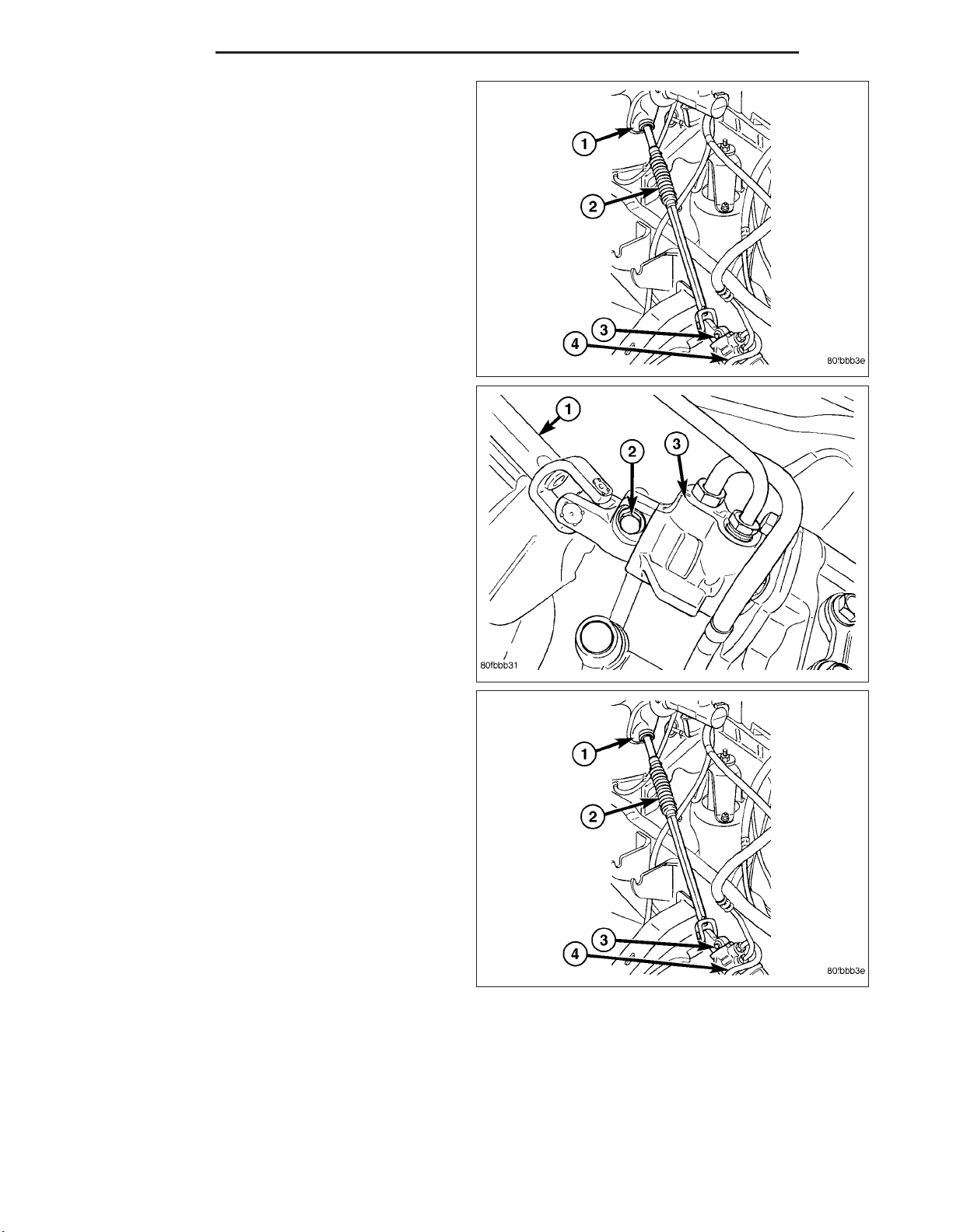
5. Remove coupler pinch bolt (1) at the steering gear
and slide shaft off gear (2).
6. Mark the pitman shaft and pitman arm (4) for
installation reference. Remove the pitman arm from
the shaft with Puller 9615 (2) (Refer to 19 STEERING/LINKAGE/PITMAN ARM - REMOVAL).
Page 37

DR/DH GEAR - LINK/COIL 19 - 37
7. Remove steering gear (1) three mounting bolts (2).
Remove the steering gear (1) from the vehicle.
INSTALLATION
1. Position the steering gear (1) the frame rail and
install the three mounting bolts (2). Tighten the
mounting bolts to 196 N·m (145 ft. lbs.).
2. Align steering coupler (1) on gear shaft (2). Install
pinch bolt and tighten to 49 N·m (36 ft. lbs.) torque.
Page 38

19 - 38 GEAR - LINK/COIL DR/DH
3. Align and install the pitman arm (5) (Refer to 19 STEERING/LINKAGE/PITMAN ARM - INSTALLATION).
4. Install the washer and retaining nut (4) on the pitman shaft. Tighten the nut to 305 N·m (225 ft. lbs.).
5. Connect fluid hoses to steering gear (Refer to 19 - STEERING/PUMP/HOSES - INSTALLATION), tighten to 31
N·m (23 ft. lbs.).
6. Add fluid, (Refer to 19 - STEERING/PUMP - STANDARD PROCEDURE).
7. Reset the toe and center the steering wheel (Refer to 2 - SUSPENSION/WHEEL ALIGNMENT - STANDARD
PROCEDURE).
ADJUSTMENTS
ADJUSTMENT
CAUTION: Steering gear must be adjusted in the proper order. If adjustments are not performed in order,
gear damage and improper steering response may result.
NOTE: Adjusting the steering gear in the vehicle is not recommended. Remove gear from the vehicle and
drain the fluid. Then mount gear in a vise to perform adjustments.
1. Remove the steering gear from the vehicle (Refer to 19 - STEERING/GEAR - REMOVAL).
2. Mount the gear carefully into a soft-jawed vise.
CAUTION: Do not overtighten the vise on the gear case. This may affect the adjustment
3. Hold the steering gear upside down over a drain pan and rotate the input shaft back and forth several times
lock-to-lock to discharge the fluid from the steering gear
4. Rotate the input shaft to the left stop and then back-off approximately 45 degrees. Using an inch-pound torque
wrench on the input shaft, record the peak torque required to slowly and evenly rotate the input shaft clockwise
1
⁄2turn (180 degrees) starting from the 45 degree position. This peak torque reading is the preload torque. The
preload torque must be within2-10in-lbs.
5. Rotate the input shaft to its center of travel (approximately 1.5 turns from either stop). Place the torque wrench
on the input shaft with the handle in the vertical position. Rotate the torque wrench slowly and evenly
degrees) each side of center and record the peak torque measure on or near center. This total on-center torque
reading must be5-9in-lbs higher than the previously measured preload torque without exceeding a total of 17
in-lbs. The value of the total on-center minus the preload torque is defined as the meshload torque
6. If required, adjust the on-center torque by loosening the adjuster screw lock nut and turning the adjuster screw
until the total on-center and meshload torque readings fall within the specified values. Turn the adjuster screw
clockwise to increase and counterclockwise to decrease the torque reading. While holding the adjuster screw in
place, tighten the lock nut to 34 N·m (25 ft. lbs.).
7. Re-check the preload and on-center torque readings.
8. Install pitman arm on the steering gear (Refer to 19 - STEERING/LINKAGE/PITMAN ARM - INSTALLATION).
9. Reinstall steering gear to the vehicle (Refer to 19 - STEERING/GEAR - INSTALLATION).
1
⁄4turn (90
Page 39

DR/DH GEAR - LINK/COIL 19 - 39
SPECIFICATIONS
POWER STEERING GEAR
SPECIFICATIONS
DESCRIPTION SPECIFICATION
Steering Gear
Type
Gear Code & Ratio 12.5:1
TORQUE SPECIFICATIONS
DESCRIPTION N·m Ft. Lbs. In. Lbs.
Preload
Torque
Meshload Torque 0.56-1.02 — 5-9
0.23-1.13 — 2-10
Recirculating Ball
+ Preload (17 Max)
TORQUE CHART
TORQUE SPECIFICATIONS
DESCRIPTION N·m Ft. Lbs. In. Lbs.
Steering Gear Mounting
Frame Bolts
Power Steering Line
Pressure
Power Steering Line
Return
Power Steering Line
Pressure Line To Pump
Steering Gear
Adjustment Screw Locknut
Steering Gear
Pitman Shaft Nut
Steering Gear
Pitman Shaft Cover Bolts
Steering Gear
Valve Housing to Gear
Bolts
Steering Gear
Retainer Ring Screw
Steering Gear
Retainer Ring
196 145 —
32 23 —
54 40 —
37 27 —
34 25 —
305 225 —
68 50 —
54 40 —
2.26 — 20
97 72 —
Page 40

19 - 40 GEAR - LINK/COIL DR/DH
SPECIAL TOOLS
POWER STEERING GEAR
PITMAN ARM REMOVAL TOOL - 9615
Page 41

DR/DH GEAR - LINK/COIL 19 - 41
Page 42

19 - 42 GEAR - LINK/COIL DR/DH
PITMAN SHAFT SEAL
REMOVAL
REMOVAL - GAS ENGINE
1. Seperate the pitman arm from the gear box (Refer to 19 - STEERING/LINKAGE/PITMAN ARM - REMOVAL).
2. Clean exposed end of pitman shaft and housing with a wire brush.
3. Rotate the steering wheel from stop to stop and count the number of turns.
4. Center the steering wheel by rotating it from the stop back 1 1/2 turns to achieve center position.
5. Remove the pitman shaft cover bolts.
NOTE: The pitman shaft will not clear the housing if it is not centered.
6. Remove the pitman shaft from the gear.
7. Remove dust seal from the housing with a special
tool (2).
CAUTION: Use care not to score the housing bore
when prying out seals and washer.
8. Remove retaining ring with snap ring pliers.
9. Remove washer from the housing.
NOTE: Tighten the slide hammer adapter 8990 into
the seal using wrenches, in order to make a tight
fit to pull the seal out. If this is not performed the
seal may tear on the removal making it difficult to
remove.
10. Remove oil seal from the housing with a special
tool 8990 with slide hammer C-3752. (2).
REMOVAL - DIESEL
1. Seperate the pitman arm from the gear box (Refer to 19 - STEERING/LINKAGE/PITMAN ARM - REMOVAL).
2. Remove the steering gear box (Refer to 19 - STEERING/GEAR - REMOVAL).
3. Install the steering gear in a soft jawed bench vise.
4. Clean exposed end of pitman shaft and housing with a wire brush.
5. Rotate the input shaft with a 12 point socket (2)
from stop to stop and count the number of turns.
6. Center the input shaft (4) by rotating it from the
stop 1/2 of the total amount of turns.
Page 43

DR/DH GEAR - LINK/COIL 19 - 43
7. Remove the pitman shaft cover bolts.
NOTE: The pitman shaft will not clear the housing if it is not centered.
8. Remove the pitman shaft from the gear (1).
9. Remove dust seal from the housing with a special
tool 8990 (2).
CAUTION: Use care not to score the housing bore
when prying out seals.
10. Remove retaining ring with snap ring pliers.
11. Remove washer from the housing.
NOTE: Tighten the slide hammer adapter 8990 into
the seal using wrenches, in order to make a tight
fit to pull the seal out. If this is not performed the
seal may tear on the removal making it difficult to
remove.
12. Remove oil seal from the housing with a special
tool 8990 (2) with slide hammer C-3752..
INSTALLATION
INSTALLATION - GAS ENGINE
NOTE: Generous amounts of the high temperature
grease from the seal kit should be applied to areas
between the pitman shaft bearing and oil seals
and also between the dust seals and snap ring.
1. Coat the oil seal and washer with high temp
grease.
NOTE: Install the oil seal with the lip facing
inward. Flat side of the oil seal should be against
the washer.
2. Install the oil seal with special tool 8989 driver (2)
and C-4171 handle (1).
3. Install backup washer.
4. Install the retainer ring with snap ring pliers.
5. Coat the dust seal with high temp grease.
6. Install the dust seal with a driver (2) and handle (1).
Page 44

19 - 44 GEAR - LINK/COIL DR/DH
7. Install protective seal protector 8993 (2) over the
shaft (1).
8. Install the pitman shaft into the steering gear until it
fully seats into the bearing.
9. Install the new cover bolts and tighten to 68 N·m
(50 ft. lbs.).
10. Install the pitman arm (Refer to 19 - STEERING/
LINKAGE/PITMAN ARM - INSTALLATION).
INSTALLATION - DIESEL
NOTE: Generous amounts of the high temperature
grease from the seal kit should be applied to areas
between the pitman shaft bearing and oil seals
and also between the dust seals and snap ring.
1. Coat the oil seal and washer with high temp
grease.
NOTE: Install the oil seal with the lip facing
inward. Flat side of the oil seal should be against
the washer.
2. Install the oil seal with special tool 8989 driver (2)
and C-4171 handle (1).
3. Install backup washer.
4. Install the retainer ring with snap ring pliers.
5. Coat the dust seal with high temp grease.
6. Install the dust seal with special tool 8989 driver (2) and C-4171 handle (1).
7. Install protective seal protector 8993 (2) over the
shaft (1).
8. Install the pitman shaft into the steering gear until it
fully seats into the bearing.
9. Install the new cover bolts and tighten to 68 N·m
(50 ft. lbs.).
10. Install the steering gear (Refer to 19 - STEER-
ING/GEAR - INSTALLATION).
11. Install the pitman arm (Refer to 19 - STEERING/
LINKAGE/PITMAN ARM - INSTALLATION).
12. Perform a wheel alignment (Refer to 2 - SUS-
PENSION/WHEEL ALIGNMENT - STANDARD
PROCEDURE).
Page 45

DR/DH GEAR - LINK/COIL 19 - 45
STEERING GEAR INPUT SHAFT SEAL
REMOVAL
1. Remove the steering gear from the vehicle (Refer to 19 - STEERING/GEAR - REMOVAL).
CAUTION: Do not overtighten the vise on the gear case. This may affect the adjustment
2. Mount the steering gear upside down over a drain pan in a soft jawed vise.
3. Place a drain pan under the gear and rotate the input shaft back and forth several times lock-to-lock to discharge
the fluid from the steering gear
4. Drain all the remaining fluid from the gear.
5. Rotate the input shaft (4) from stop to stop and
count the number of turns using a 12 point socket
(2).
NOTE: The pitman shaft will not clear the housing
if it is not centered.
6. Center the input shaft (4) by rotating it from the
stop back 1 1/2 turns to achieve center position.
7. Remove the pitman shaft (Refer to 19 - STEERING/GEAR/PITMAN SHAFT - REMOVAL).
8. Remove the four bolts securing the valve housing
(1).
9. Remove the valve housing (1) from the steering
gear (3).
Page 46

19 - 46 GEAR - LINK/COIL DR/DH
10. Remove the valve housing (1) and wormshaft
assembly from the steering gear housing and
place the valve housing in a soft jawed vise.
11. Remove the retainer ring (3) set screw (1) from
the valve housing.
12. Using special tool reatainer ring wrench 8988 (1)
to remove the steering gear worm thrust bearing
reatainer ring.
Page 47

DR/DH GEAR - LINK/COIL 19 - 47
13. Separate the wormshaft assembly from the valve
housing, Then remove the wormshaft assembly
from the vise.
14. Remove the dust seal (3) with a pick (1).
CAUTION: Use care not to score the housing bore
when removing seals.
15. Remove the snap ring (2) with snap ring pliers
(1).
Page 48

19 - 48 GEAR - LINK/COIL DR/DH
16. Using special tool slide hammer C-3752 (1) with
adapter 8990 (1) remove the oil seal.
INSTALLATION
1. Inspect the piston teflon seals for damage. Replace
if needed.
NOTE: To replace the teflon seals, use a pick to
remove the teflon o-ring and the rubber o-ring
underneath. Install a new rubber o-ring in the piston seal grove and a new teflon o-ring over the top
of it.
2. Install the valve into the valve housing (1).
3. Thread the retainer ring into the valve housing (1).
Tighten to 97 N·m (72 ft. lbs.).
NOTE: It is very important to make sure to compensate for the added length of the torque wrench
when torquing to proper specifications.
4. Install the retainer ring set screw. Tighten to 2.26
N·m (20 in. lbs.)
5. Clean the steering gear housing.
CAUTION: Valve assembly must be centered to the
housing (1).
6. Install the valve assembly (2) into the steering
gear. Tighten the new bolts to 54 N·m (40 ft. lbs.)
Page 49

DR/DH GEAR - LINK/COIL 19 - 49
7. Install the input shaft seal protector 8986 (2).
8. Coat the new seal in high temp grease and Install
the new oil seal using special tool 8987 driver (2)
and C-4171 handle (3).
NOTE: Drive the oil seal into the housing until the
outer edge does not quite clear the snap ring
groove.
9. Insert the snap ring into the housing. Using special
tool 8987 driver (2) and C-4171 handle (3) push
the snap ring and oil seal together until the snap
ring seats in the groove.
NOTE: Generous amounts of the high temperature
grease from the seal kit should be applied to areas
between the pitman shaft bearing and oil seals
and also between the dust seals and snap ring.
10. Install the new dust seal using high temp grease, special tool C-4171 (driver) (3) and 8987 (handle)(2).
11. Check to make sure the gear is centered in the
middle tooth (1) before installing the pitman shaft.
12. Install the pitman shaft into the steering gear (Refer to 19 - STEERING/GEAR/PITMAN SHAFT - INSTALLA-
TION).
13. Perform over-center meshload adjustment (Refer to 19 - STEERING/GEAR - ADJUSTMENTS).
14. Install the steering gear to the vehicle (Refer to 19 - STEERING/GEAR - INSTALLATION).
Page 50

19 - 50 GEAR - LINK/COIL DR/DH
15. Perform a wheel alignment (Refer to 2 - SUSPENSION/WHEEL ALIGNMENT - STANDARD PROCEDURE).
PITMAN SHAFT
REMOVAL
REMOVAL - GAS
1. Separate the pitman arm from the gear box (Refer
to 19 - STEERING/LINKAGE/PITMAN ARM REMOVAL).
2. Clean exposed end of pitman shaft (1) and housing
with a wire brush.
3. Rotate the steering wheel from stop to stop and
count the number of turns.
4. Center the steering wheel by rotating it from the
stop back 1 1/2 turns to achieve center position.
5. Remove the pitman shaft cover bolts.
NOTE: The pitman shaft will not clear the housing
if it is not centered.
6. Remove the pitman shaft (1) from the gear.
7. Remove the cover if needed by loosing the
adjuster nut (4), Then removing the cover (3) from the pitman shaft.
REMOVAL - DIESEL
1. Separate the pitman arm from the gear box (Refer to 19 - STEERING/LINKAGE/PITMAN ARM - REMOVAL).
2. Remove the steering gear box (Refer to 19 - STEERING/GEAR - REMOVAL).
3. Install the steering gear in a soft jawed bench vise.
4. Clean exposed end of pitman shaft and housing
with a wire brush.
5. Rotate the stub shaft with a 12 point socket (2)
from stop to stop and count the number of turns.
6. Center the stub shaft (4) by rotating it from the stop
1/2 of the total amount of turns.
Page 51

DR/DH GEAR - LINK/COIL 19 - 51
7. Remove the pitman shaft cover bolts (3).
NOTE: The pitman shaft will not clear the housing
if it is not centered.
8. Remove the pitman shaft (1) from the gear.
9. Remove the cover (3) if needed by loosing the
adjuster nut (4), Then removing the cover from the
pitman shaft.
INSTALLATION
INSTALLATION - GAS
1. Coat the seal with power steering fluid.
2. Install pitman shaft (1) into the steering gear until it
fully seats into the bearing.
3. Install the new cover bolts and tighten to 68 N·m
(50 ft. lbs.).
4. Perform over-center meshload adjustment, (Refer
to 19 - STEERING/GEAR - ADJUSTMENTS).
5. Install the pitman arm (Refer to 19 - STEERING/LINKAGE/PITMAN ARM - INSTALLATION).
6. Perform a wheel alignment (Refer to 2 - SUSPENSION/WHEEL ALIGNMENT - STANDARD PROCEDURE).
Page 52

19 - 52 GEAR - LINK/COIL DR/DH
INSTALLATION - DIESEL
1. Coat the seal with power steering fluid.
2. Install the pitman shaft (1) into the steering gear
until it fully seats into the bearing.
3. Install the new cover bolts (3) and tighten to 68
N·m (50 ft. lbs.).
4. Perform over-center meshload adjustment (Refer to
19 - STEERING/GEAR - ADJUSTMENTS).
5. Install the steering gear (Refer to 19 - STEERING/GEAR - INSTALLATION).
6. Install the pitman arm (Refer to 19 - STEERING/LINKAGE/PITMAN ARM - INSTALLATION).
7. Perform a wheel alignment (Refer to 2 - SUSPENSION/WHEEL ALIGNMENT - STANDARD PROCEDURE).
Page 53

DR/DH LINKAGE - INDEPENDENT FRONT SUSPENSION 19 - 53
LINKAGE - INDEPENDENT FRONT SUSPENSION
TABLE OF CONTENTS
page page
LINKAGE - INDEPENDENT FRONT
SUSPENSION
DIAGNOSIS AND TESTING
OUTER TIE ROD END ..................53
TIE ROD END
REMOVAL - OUTER TIE ROD END ..........53
INSTALLATION - OUTER TIE ROD END ......54
LINKAGE - INDEPENDENT FRONT SUSPENSION
DIAGNOSIS AND TESTING
OUTER TIE ROD END
NOTE: If the outer tie rod end is equipped with a lubrication fitting, grease the joint then road test the vehicle before performing test.
1. Raise the front of the vehicle. Place safety floor stands under both lower control arms as far outboard as possible. Lower the vehicle to allow the stands to support some or all of the vehicle weight.
2. Remove the front tires.
3. Mount a dial indicator solidly to the vehicle steering knuckle and then zero the dial indicator.
4. Position indicator plunger on the topside of the outer tie rod end.
NOTE: The dial indicator plunger must be perpendicular to the machined surface of the outer tie rod end.
5. Position a pry bar in order to pry downwards on the outer tie rod end.
6. If the travel exceeds 0.5 mm (0.020 in.), replace the outer tie rod end (Refer to 19 - STEERING/LINKAGE/TIE
ROD END - REMOVAL).
7. If the outer tie rod end is within specs reinstall the front tires (Refer to 22 - TIRES/WHEELS/WHEELS - STANDARD PROCEDURE).
TIE ROD END
REMOVAL - OUTER TIE ROD END
NOTE: Do not twist the boot anytime during
removal or installation.
1. Loosen the jam nut.
2. Remove the outer tie rod end nut from the ball stud
(1).
3. Separate the tie rod ball stud (1) from the knuckle
with Remover 8677 (2).
4. Unthread the outer tie rod end (1) from the inner tie
rod.
Page 54

19 - 54 LINKAGE - INDEPENDENT FRONT SUSPENSION DR/DH
INSTALLATION - OUTER TIE ROD END
NOTE: Do not twist the boot at anytime during
removal or installation.
1. Thread the outer tie rod end (3) onto the inner tie
rod (2), to it’s original position.
2. Install the outer tie rod end (3) into the steering
knuckle.
3. Tighten the ball stud nut on the ball stud to 61 N·m
(45 ft. lbs.) then an additional 90°.
4. Set wheel toe pattern, (Refer to 2 - SUSPENSION/
WHEEL ALIGNMENT - STANDARD PROCEDURE).
5. Tighten jam nut (1) to 75 N·m (55 ft. lbs.).
Page 55

DR/DH LINKAGE - LINK/COIL 19 - 55
LINKAGE - LINK/COIL
TABLE OF CONTENTS
page page
LINKAGE - LINK/COIL
DESCRIPTION .........................55
STANDARD PROCEDURE
LUBRICATION ........................56
SPECIFICATIONS
TORQUE CHART ......................56
SPECIAL TOOLS
STEERING LINKAGE ...................57
DAMPER
REMOVAL .............................58
INSTALLATION .........................58
DRAG LINK
REMOVAL .............................58
LINKAGE - LINK/COIL
DESCRIPTION
The steering linkage is comprised of a tie rod end (5),
tie rod, drag link (7), steering damper (9) and pitman
arm (2).
INSTALLATION .........................58
PITMAN ARM
REMOVAL .............................59
INSTALLATION .........................60
TIE ROD END
REMOVAL .............................60
INSTALLATION .........................61
TRACK BAR
REMOVAL .............................61
INSTALLATION .........................62
Page 56

19 - 56 LINKAGE - LINK/COIL DR/DH
CAUTION: If any steering components are
replaced or serviced an alignment must be performed.
NOTE: To avoid damaging ball stud seals, use
Puller C-3894–A (3) or an appropriate puller to
remove tie rod ends (5).
STANDARD PROCEDURE
LUBRICATION
Periodic lubrication of the steering system components is required. Refer to Lubrication And Maintenance for the
recommended maintenance schedule.
The following components must be lubricated:
• Tie rod
• Tie rod end
• Drag link
SPECIFICATIONS
TORQUE CHART
TORQUE SPECIFICATIONS
DESCRIPTION N·m Ft. Lbs. In. Lbs.
Pitman Arm
Gear Shaft Nut
Drag Link
Pitman Arm
Drag Link
Tie Rod
Drag Link
Adjuster Clamp
Tie Rod End
Knuckle
Tie Rod End
Adjuster Clamp
Stabilizer Bar Link to Axle 68 50 —
Steering Damper
Axle
Steering Damper
Tie Rod
Then an additional 90°
Then an additional 90°
300 225 —
88 65 —
54
Then an additional 90°
61 45 —
54
Then an additional 90°
61 45 —
95 70 —
81 60 —
40
40
—
—
Page 57

DR/DH LINKAGE - LINK/COIL 19 - 57
SPECIAL TOOLS
STEERING LINKAGE
PITMAN ARM REMOVAL TOOL - 9615
Page 58

19 - 58 LINKAGE - LINK/COIL DR/DH
DAMPER
REMOVAL
1. Remove the steering damper mounting nuts and bolts.
2. Slide the damper from the isolation bushing.
3. Remove the damper.
INSTALLATION
1. Install the steering damper on the axle and isolation bushing. Tighten nut to 95 N·m (75 ft. lbs.).
2. Install the steering damper on the tie rod. Tighten nut to 81 N·m (60 ft. lbs.).
DRAG LINK
REMOVAL
1. Remove the draglink nut (2) from the pitman arm
side (1).
2. Remove the drag link nut from the knuckle side.
3. Remove the drag link (2) from the right knuckle
and pitman arm (1) with Puller C-3894A (3).
INSTALLATION
1. Install the drag link (2) to the pitman arm (1). Install
the nut and tighten to 88 N·m (65 ft. lbs.).
2. Install the drag link to the right steering knuckle.
Install the nut and tighten to 54 N·m (40 ft. lbs.)
Then an additional 90°.
3. Install tie rod to the left steering knuckle and drag
link. Install the nuts and tighten to 54 N·m (40 ft.
lbs.) Then an additional 90°.
4. Remove the supports and lower the vehicle to the
surface. Center steering wheel and adjust toe,
(Refer to 2 - SUSPENSION/WHEEL ALIGNMENT STANDARD PROCEDURE).
5. After adjustment tighten tie rod adjustment sleeve
clamp bolts to 61 N·m (45 ft. lbs.).
NOTE: Position the clamp on the sleeve so retaining bolt is located on the bottom side of the sleeve.
Page 59

DR/DH LINKAGE - LINK/COIL 19 - 59
PITMAN ARM
REMOVAL
1. Remove the drag link nut (2) from the pitman arm
(1).
2. Install puller C-3894-A (3) and separate the drag
link (2) from the pitman arm (1).
3. Mark the pitman arm (2) and shaft positions for
installation reference. Remove the nut (3) and
washer (4) from the pitman arm (2).
4. Remove the pitman arm (4) with Puller 9615 (2) or
an equivalent pitman arm puller tool.
Page 60

19 - 60 LINKAGE - LINK/COIL DR/DH
INSTALLATION
1. Align reference marks and install pitman arm.
2. Install the lock washer and retaining nut on the pitman shaft and tighten nut to 251 N·m (185 ft. lbs.).
3. Install the drag link (1) to the pitman arm (5). Install
the nut (4) and tighten to 54 N·m (40 ft. lbs.) Then
an additional 90°.
4. Remove the supports and lower the vehicle to the
surface. Center steering wheel and adjust toe,
(Refer to 2 - SUSPENSION/WHEEL ALIGNMENT STANDARD PROCEDURE).
5. After adjustment tighten tie rod adjustment sleeve
clamp bolts to 61 N·m (45 ft. lbs.).
NOTE: Position the clamp on the sleeve so retaining bolt is located on the bottom side of the
sleeve.
TIE ROD END
REMOVAL
1. Remove tie rod nuts (1).
2. Remove tie rod from drag link and left knuckle with
Puller C-4150A.
Page 61

DR/DH LINKAGE - LINK/COIL 19 - 61
INSTALLATION
1. Install tie rod (2) to the left steering knuckle and
drag link. Install the nuts (1) and tighten to 54 N·m
(40 ft. lbs.) Then an additional 90°.
2. Remove the supports and lower the vehicle to the
surface. Center steering wheel and adjust toe,
(Refer to 2 - SUSPENSION/WHEEL ALIGNMENT STANDARD PROCEDURE).
3. After adjustment tighten tie rod adjustment sleeve
clamp bolts to 61 N·m (45 ft. lbs.).
NOTE: Position the clamp on the sleeve so retaining bolt is located on the bottom side of the sleeve.
TRACK BAR
REMOVAL
1. Raise and support the axle.
2. Remove the track bar bolts (2) and nuts (3).
3. Remove the track bar (1).
Page 62

19 - 62 LINKAGE - LINK/COIL DR/DH
INSTALLATION
1. Install the track bar (1).
2. Install the new bolts (2) and nuts (3). Tighten to
203 N·m (150 ft lbs.).
3. Remove the supports under the axle and lower the
vehicle to the ground.
Page 63

DR/DH PUMP 19 - 63
PUMP
TABLE OF CONTENTS
page page
PUMP
DESCRIPTION .........................63
OPERATION ...........................64
DIAGNOSIS AND TESTING
PUMP LEAKAGE ......................64
STANDARD PROCEDURE
FLUSHING POWER STEERING SYSTEM . . . 64
POWER STEERING PUMP - INITIAL
OPERATION .........................65
REMOVAL
GAS ENGINE .........................66
DIESEL ENGINE ......................66
INSTALLATION
GAS ENGINE .........................67
DIESEL ENGINE ......................67
SPECIFICATIONS
TORQUE CHART ......................68
FLUID
DESCRIPTION .........................68
STANDARD PROCEDURE
POWER STEERING FLUID LEVEL
CHECKING ..........................68
FLUID COOLER
REMOVAL .............................69
INSTALLATION .........................70
HOSES - I.F.S.
REMOVAL
RETURN HOSE - GEAR TO COOLER ......71
PRESSURE HOSE .....................71
RETURN HOSE - RESERVOIR TO COOLER . 71
INSTALLATION
RETURN HOSE - GEAR TO COOLER ......72
PRESSURE HOSE .....................72
RETURN HOSE - RESERVOIR TO COOLER . 72
HOSES - LINK/COIL
REMOVAL
RETURN HOSE - GEAR TO COOLER ......73
PRESSURE HOSE .....................73
RETURN HOSE - RESERVOIR TO COOLER . 73
INSTALLATION
RETURN HOSE - GEAR TO COOLER ......74
PRESSURE HOSE .....................74
RETURN HOSE - RESERVOIR TO COOLER . 74
SWITCH-POWER STEERING PRESSURE
DESCRIPTION .........................75
OPERATION ...........................75
REMOVAL - 5.7L - HD VEHICLES ONLY ......75
INSTALLATION - 5.7L - HD VEHICLES ONLY . . 75
PULLEY
REMOVAL .............................76
INSTALLATION .........................76
RESERVOIR
REMOVAL .............................76
INSTALLATION .........................77
PUMP
DESCRIPTION
CAUTION: MOPART ATF+4 is to be used in the power steering system. No other power steering or automatic transmission fluid is to be used in the system. Damage may result to the power steering pump and
system if any other fluid is used, and do not overfill.
The pump is connected to the steering gear via the pressure hose and the return hose. The pump shaft has a
pressed-on pulley that is belt driven by the crankshaft pulley.
All vehicles are equipped with a power steering fluid cooler.
Page 64

19 - 64 PUMP DR/DH
NOTE: Power steering pumps are not interchangeable with pumps installed on other vehicles.
OPERATION
Hydraulic pressure is provided for the power steering
gear by the belt driven power steering pump (2). The
power steering pumps are constant flow rate and displacement, vane-type pumps.
DIAGNOSIS AND TESTING
PUMP LEAKAGE
The pump is serviced as an assembly and should not be disassembled. The plastic pump reservoir and the reservoir o-rings can be replaced.
Check for leaks in the following areas:
• Pump shaft seal behind the pulley
• Pump to reservoir O-ring
• Reservoir cap
• Pressure and return lines
• Flow control valve fitting
STANDARD PROCEDURE
FLUSHING POWER STEERING SYSTEM
Flushing is required when the power steering/hydraulic booster system fluid has become contaminated. Contaminated fluid in the steering/booster system can cause seal deterioration and affect steering gear/booster spool valve
operation.
1. Raise the front end of the vehicle off the ground until the wheels are free to turn.
2. Remove the return line from the pump.
NOTE: If vehicle is equipped with a hydraulic booster remove both return lines from the pump.
3. Plug the return line port/ports at the pump.
4. Position the return line/lines into a large container to catch the fluid.
5. While an assistant is filling the pump reservoir start the engine.
6. With the engine running at idle turn the wheel back and forth.
NOTE: Do not contact or hold the wheel against the steering stops.
7. Run a quart of fluid through the system then stop the engine and install the return line/lines.
8. Fill the system with fluid and perform Steering Pump Initial Operation, (Refer to 19 - STEERING/PUMP - STANDARD PROCEDURE).
9. Start the engine and run it for fifteen minutes then stop the engine.
Page 65

DR/DH PUMP 19 - 65
10. Remove the return line/lines from the pump and plug the pump port/ports.
11. Pour fresh fluid into the reservoir and check the draining fluid for contamination. If the fluid is still contaminated,
then flush the system again.
12. Install the return line/lines and perform Steering Pump Initial Operation, (Refer to 19 - STEERING/PUMP -
STANDARD PROCEDURE).
POWER STEERING PUMP - INITIAL OPERATION
WARNING: THE FLUID LEVEL SHOULD BE CHECKED WITH ENGINE OFF TO PREVENT INJURY FROM MOVING COMPONENTS.
CAUTION: MOPART ATF+4 is to be used in the power steering system. No other power steering or automatic transmission fluid is to be used in the system. Damage may result to the power steering pump and
system if any other fluid is used, and do not overfill.
Wipe filler cap clean, then check the fluid level. The dipstick should indicate COLD when the fluid is at normal
temperature.
1. Turn steering wheel all the way to the left
2. Fill reservoir up to FULL HOT level and crank engine until it just starts. (DO NOT TURN STEERING WHEEL)
Then turn vehicle off. And re check fluid level, to Full COLD.
3. Crank engine again until it just starts, (DO NOT MOVE STEERING WHEEL) and turn vehicle off. Recheck fluid
level to Full COLD.
4. Turn engine on again, (DO NOT MOVE STEERING WHEEL) and let the vehicle idle for 5 minutes. If possible
apply a 20 in-Hg vacuum to the reservoir, while engine is idling.
5. Turn engine off and recheck fluid level, to FULL COLD.
6. If the Steering gear is replaced. ensure reservoir is at FULL HOT level, start engine and turn wheel to left. Stop
Engine and recheck fluid level to FULL HOT. Start engine and turn wheel to the right. Stop engine and check
fluid level is at FULL COLD.
7. Fill the pump fluid reservoir to the proper level and let the fluid settle for at least two (2) minutes.
8. Start the engine. With the engine idling maintain the fluid level.
9. Raise the front wheels off the ground.
10. Slowly turn the steering wheel lock-to-lock 20 times with the engine off while checking the fluid level.
NOTE: For vehicles with long return lines or oil coolers turn wheel 40 times.
11. Lower the front wheels and let the engine idle for two minutes.
12. Turn the steering wheel in both direction and verify power assist and quiet operation of the pump.
If the fluid is extremely foamy or milky looking, allow the vehicle to stand a few minutes and repeat the procedure.
Page 66

19 - 66 PUMP DR/DH
CAUTION: Do not run a vehicle with foamy fluid for an extended period. This may cause pump damage.
REMOVAL
GAS ENGINE
1. Drain and siphon the power steering fluid from the
reservoir.
2. Remove the serpentine belt.
CAUTION: Do not remove the fitting on the pump
that the high pressure hose screws into. The fitting may come loose unless it is backed up using
another wrench. If the fitting does come loose, it
must be retightened before continuing. (57 - 67Nm,
40 - 50 lbft) If this fitting comes out of the pump
body, the internal spring and valve parts will fall
out of the pump and they cannot be reinstalled
properly. If this occurs the pump needs to be
replaced with a new pump.
3. Disconnect the return hose (3).
4. Disconnect the pressure hose (4).
5. Access to remove the three bolts securing the pump to the cylinder head can be gained thru the pulley holes (1).
DIESEL ENGINE
1. Drain and siphon the power steering fluid from the reservoir.
2. Remove the serpentine belt.
CAUTION: Do not remove the fitting on the pump that the high pressure hose screws into. The fitting may
come loose unless it is backed up using another wrench. If the fitting does come loose, it must be retightened before continuing. (57 - 67Nm, 40 - 50 lbft) If this fitting comes out of the pump body, the internal
spring and valve parts will fall out of the pump and they cannot be reinstalled properly. If this occurs the
pump needs to be replaced with a new pump.
3. Disconnect the return hose.
4. Disconnect the pressure hose.
5. Access to remove the three bolts securing the pump to the cylinder head can be gained thru the pulley holes.
6. Loosen the pump bracket to the block.
7. Remove the 6 intake plenum bolts (1).
8. loosen the inner cooler tube clamp at the intake
plenum and remove the intake plenum.
9. Loosen the inner cooler tube clamp at the radiator
support side and remove the tube from the vehicle.
10. Remove the power steering pump (2) from the top
of the engine compartment where the intake plenum was.
Page 67

DR/DH PUMP 19 - 67
INSTALLATION
GAS ENGINE
1. Align the pump with the mounting holes in the left
cylinder head.
2. Install 3 pump mounting bolts through the pulley
access holes (1). Tighten the bolts to 28 N·m (21 ft.
lbs.).
3. Reconnect the pressure line (4) and return hose (3)
to the pump and reservoir (2). Tighten the pressure
line to 37 N·m (27 ft. lbs.).
4. Install the serpentine drive belt, (Refer to 7 COOLING/ACCESSORY DRIVE/DRIVE BELTS INSTALLATION).
5. Fill the power steering pump, (Refer to 19 STEERING/PUMP - STANDARD PROCEDURE).
DIESEL ENGINE
1. Set the power steering pump (2) in place in the
engine compartment from the top.
2. Install the inner cooler tube.
3. Tighten the inner cooler tube clamp at the radiator
support side.
4. Install the 6 intake plenum bolts (2).
5. Tighten the inner cooler tube clamp at the intake
plenum.
6. Install 3 pump mounting bolts through the pulley access holes. Tighten the bolts to 28 N·m (21 ft. lbs.).
7. Tighten the pump bracket to the block.
8. Reconnect the pressure line and return hose to the pump and reservoir. Tighten the pressure line to 37 N·m (27
ft. lbs.).
9. Install the serpentine drive belt, (Refer to 7 - COOLING/ACCESSORY DRIVE/DRIVE BELTS - INSTALLATION).
10. Fill the power steering pump, (Refer to 19 - STEERING/PUMP - STANDARD PROCEDURE).
Page 68

19 - 68 PUMP DR/DH
SPECIFICATIONS
TORQUE CHART
TORQUE SPECIFICATIONS
DESCRIPTION N·m Ft. Lbs. In. Lbs.
Power Steering Pressure
Switch
Power Steering Line
Pressure Line
Power Steering Line
Return Line
HD
Power Steering Line
Return Line
LD
Power Steering Line
Pressure Line To Pump
Power Steering Pump
Mounting Bolts
Power Steering Pump
Reservoir Bolts
Power Steering Pump
Bracket Bolts
10 — 80
32 23 —
51 38 —
70 52 —
37 27 —
28 27 —
13 10 120
5562
FLUID
DESCRIPTION
NOTE: It is normal that some pressure will build up inside the reservoir, especially, with a warm vehicle. A
slight popping noise upon removal of the cap is normal. The fluid level should read between the ADD and
the FULL COLD marks. When the fluid is hot it should read between ADD and FULL HOT marks. Only add
fluid when the vehicle is cold.
The recommended fluid for the power steering system is MoparT ATF +4.
MoparT ATF+4, when new is red in color. The ATF+4 is dyed red so it can be identified from other fluids used in the
vehicle such as engine oil or antifreeze. The red color is not permanent and is not an indicator of fluid condition, As
the vehicle is driven, the ATF+4 will begin to look darker in color and may eventually become brown. THIS IS NOR-
MAL. ATF+4 also has a unique odor that may change with age. Consequently, odor and color cannot be used to
indicate the fluid condition or the need for a fluid change.
STANDARD PROCEDURE
POWER STEERING FLUID LEVEL CHECKING
WARNING: FLUID LEVEL SHOULD BE CHECKED WITH THE ENGINE OFF TO PREVENT PERSONAL INJURY
FROM MOVING PARTS.
CAUTION: MOPART ATF+4 is to be used in the power steering system. No other power steering or automatic transmission fluid is to be used in the system. Damage may result to the power steering pump and
system if any other fluid is used, and do not overfill.
Page 69

DR/DH PUMP 19 - 69
The power steering fluid level can be viewed on the dipstick attached to the filler cap. There are two ranges listed
on the dipstick, COLD and HOT. Before opening power steering system, wipe the reservoir filler cap free of dirt and
debris. Remove the cap and check the fluid level on its dipstick. When the fluid is at normal ambient temperature,
approximately 21°C to 27°C (70°F to 80°F), the fluid level should read between the minimum and maximum area of
the cold range. When the fluid is hot, fluid level is allowed to read up to the highest end of the HOT range. Only add
fluid when the vehicle is cold.
Use only MoparT ATF+4 Do not overfill the power steering system.
FLUID COOLER
REMOVAL
1. Drain and siphon the power steering fluid.
2. Disconnect the return and supply hoses connected to the power steering fluid cooler.
3. Remove the mounting bracket bolts (2) securing
the fluid cooler (1) to the brace. (V6&V8)
(Diesel engine)
4. Remove the fluid cooler from the vehicle.
Page 70

19 - 70 PUMP DR/DH
INSTALLATION
1. Install the fluid cooler (1) to the vehicle.
2. Install the mounting bracket bolts (2) securing the
fluid cooler (1) to the brace (V6&V8).
(Diesel Engine).
3. Reclamp the return and supply hoses to the power steering fluid cooler (4).
4. Refill the power steering fluid (Refer to 19 - STEERING/PUMP - STANDARD PROCEDURE).
Page 71

DR/DH PUMP 19 - 71
HOSES - I.F.S.
REMOVAL
RETURN HOSE - GEAR TO COOLER
1. Drain and siphon the power steering system.
2. Raise and support the vehicle.
3. Disconnect the return hose at the cooler.
4. Disconnect the return hose (1) at the gear.
5. Remove the return hose from the routing clamp at
the fan shroud and then remove from the vehicle.
PRESSURE HOSE
1. Drain and siphon the power steering system.
2. Raise and support the vehicle.
3. Disconnect the pressure hose at the pump.
4. Disconnect the pressure hose (2) at the gear.
5. Remove the pressure hose from the vehicle.
RETURN HOSE - RESERVOIR TO COOLER
1. Drain and siphon the power steering system.
2. Disconnect the return hose at the reservoir.
3. Raise and support the vehicle.
4. Remove the return hose from the routing clamp at the fan shroud.
5. Disconnect the return hose at the cooler.
6. Remove the hose from the vehicle.
Page 72

19 - 72 PUMP DR/DH
INSTALLATION
RETURN HOSE - GEAR TO COOLER
1. Install the return hose to the vehicle.
2. Reconnect the return hose at the cooler.
3. Reconnect the return hose (1) at the gear. Tighten
the hose to 71 N·m (52 ft. lbs.).
4. Reattach the hose to the routing clip at the fan
shroud.
5. Remove the support and lower the vehicle.
6. Refill the power steering system, (Refer to 19 STEERING/PUMP - STANDARD PROCEDURE).
PRESSURE HOSE
NOTE: Be sure to align the pressure hose so it
does not contact the fan shroud or the frame rail.
1. Install the pressure hose to the vehicle.
2. Reconnect the pressure hose (2) at the gear.
Tighten the hose to 32 N·m (23 ft. lbs.).
3. Reconnect the pressure hose at the pump. Tighten
the hose to 36 N·m (27 ft. lbs.).
4. Remove the support and lower the vehicle.
5. Refill the power steering system, (Refer to 19 STEERING/PUMP - STANDARD PROCEDURE).
RETURN HOSE - RESERVOIR TO COOLER
1. Install the return hose to the vehicle.
2. Reconnect the return hose at the cooler.
3. Reattach the hose to the routing clip at the fan shroud.
4. Remove the support and lower the vehicle.
5. Reconnect the return hose at the reservoir.
6. Refill the power steering system, (Refer to 19 - STEERING/PUMP - STANDARD PROCEDURE).
Page 73

DR/DH PUMP 19 - 73
HOSES - LINK/COIL
REMOVAL
RETURN HOSE - GEAR TO COOLER
1. Drain and siphon the power steering system.
2. Raise and support the vehicle.
3. Disconnect the return hoseat the cooler.
4. Disconnect the return hose (2) at the gear.
5. Remove the return hose from the routing clamp at
the fan shroud and then remove from the vehicle.
PRESSURE HOSE
1. Drain and siphon the power steering system.
2. Raise and support the vehicle.
3. Disconnect the pressure hose at the pump.
4. Disconnect the pressure hose (2) at the gear (4).
5. Remove the pressure hose from the vehicle.
RETURN HOSE - RESERVOIR TO COOLER
1. Drain and siphon the power steering system.
2. Disconnect the return hose at the reservoir.
3. Raise and support the vehicle.
4. Remove the return hose from the routing clamp at the fan shroud.
5. Disconnect the return hose at the cooler.
6. Remove the hose from the vehicle.
Page 74

19 - 74 PUMP DR/DH
INSTALLATION
RETURN HOSE - GEAR TO COOLER
1. Install the return hose to the vehicle.
2. Reconnect the return hose at the cooler.
3. Reconnect the return hose (2) at the gear. Tighten
the hose to 51 N·m (38 ft. lbs.).
4. Reattach the hose to the routing clip at the fan
shroud.
5. Remove the support and lower the vehicle.
6. Refill the power steering system, (Refer to 19 STEERING/PUMP - STANDARD PROCEDURE).
PRESSURE HOSE
NOTE: Be sure to align the pressure hose so it
does not contact the fan shroud or the frame rail.
1. Install the pressure hose to the vehicle.
2. Reconnect the pressure hose (2) at the gear (4).
Tighten the hose to 32 N·m (23 ft. lbs.).
3. Reconnect the pressure hose at the pump. Tighten
the hose to 36 N·m (27 ft. lbs.).
4. Remove the support and lower the vehicle.
5. Refill the power steering system, (Refer to 19 STEERING/PUMP - STANDARD PROCEDURE).
RETURN HOSE - RESERVOIR TO COOLER
1. Install the return hose to the vehicle.
2. Reconnect the return hose at the cooler.
3. Reattach the hose to the routing clip at the fan shroud.
4. Remove the support and lower the vehicle.
5. Reconnect the return hose at the reservoir.
6. Refill the power steering system, (Refer to 19 - STEERING/PUMP - STANDARD PROCEDURE).
Page 75

DR/DH PUMP 19 - 75
SWITCH-POWER STEERING PRESSURE
DESCRIPTION
A pressure sensing switch is used in the power steering system. It is mounted on the high-pressure steering hose.
This switch will only be used with on HD vehicles with the 5.7L engines. There is no pressure switch used for the
3.7L, 4.7L, 5.9L engines or the 5.7L LD vehicle pump.
OPERATION
The switch is used on the 5.7L V-8 engines HD vehicles only.
The power steering pressure switch provides an input to the Powertrain Control Module (PCM). This input is pro-
vided during periods of high steering pump load and low engine rpm; such as during parking maneuvers. The PCM
increases the idle speed through the Idle Air Control (IAC) motor. This is done to prevent the engine from stalling
under the increased load.
When steering pump pressure exceeds 3275 kPa ± 690 kPa (475 psi ± 100 psi), the Normally Closed (NC) switch
will open and the PCM will increase the engine idle speed. This will prevent the engine from stalling.
When pump pressure drops to approximately 1379 kPa (200 psi), the switch circuit will re-close and engine idle
speed will return to its previous setting.
REMOVAL - 5.7L - HD VEHICLES ONLY
The power steering pressure switch (5) is installed in
the power steering high-pressure hose (5).
1. Disconnect electrical connector from power steering pressure switch.
2. Place a small container or shop towel beneath
switch to collect any excess fluid.
3. Remove switch. Use back-up wrench on power
steering line to prevent line bending.
INSTALLATION - 5.7L - HD VEHICLES ONLY
This switch is used only with the 5.7L V-8 engines HD
vehicles only.
1. Install power steering switch (5) into power steering
line (5).
2. Tighten to 8–11 N·m (70–100 in. lbs.) torque.
3. Connect electrical connector to switch.
4. Check power steering fluid and add as necessary.
5. Start engine and again check power steering fluid.
Add fluid if necessary.
Page 76

19 - 76 PUMP DR/DH
PULLEY
REMOVAL
CAUTION: Do not reuse the old power steering
pump pulley it is not intended for reuse. A new
pulley must be installed if removed.
1. Remove the power steering pump assembly (1),
(Refer to 19 - STEERING/PUMP - REMOVAL).
2. Remove the pulley (2) from the pump using (OTCT
7185) power steering pulley removal tool or equivalent (3).
INSTALLATION
CAUTION: Do not reuse the old power steering
pump pulley it is not intended for reuse. A new
pulley must be installed if removed.
1. Replace the pulley (2) if it’s bent, cracked, or loose.
2. Install the pulley (2) on the pump (1) using (OTCT
7771) power steering pulley installation tool or
equivalent (3) making sure it is flush with the end
of the shaft. Ensure the tool and pulley remain
aligned with the pump shaft.
3. Install the power steering pump assembly, (Refer to
19 - STEERING/PUMP - INSTALLATION).
4. Run engine until warm (5 min.) and note any belt chirp. If chirp exists, move pulley outward approximately 0.5
mm (0.020 in.). If noise increases, press on 1.0 mm (0.040 in.). Be careful that pulley does not contact
mounting bolts.
RESERVOIR
REMOVAL
1. Drain and siphon the power steering fluid from the reservoir.
2. Remove the serpentine belt.
3. Remove the power steering pump (Refer to 19 - STEERING/PUMP - REMOVAL).
4. Remove the reservoir mounting bolts.
5. Remove the reservoir.
6. Remove the rear bracket to the pump mounting bolts.
Page 77

DR/DH PUMP 19 - 77
INSTALLATION
1. Install the reservoir bracket to the pump housing. Do not reuse the o-rings (install new o-rings). Tighten bolts
to 7 N·m (62 in. lbs.).
NOTE: Ensure the reservoir is fully seated onto the pump.
2. Install the reservoir to the bracket/pump body.
3. Install the reservoir mounting bolts. Tighten bolts to 13 N·m (120 in. lbs.).
4. Install the power steering pump (Refer to 19 - STEERING/PUMP - INSTALLATION).
5. Install the serpentine drive belt, (Refer to 7 - COOLING/ACCESSORY DRIVE/DRIVE BELTS - INSTALLATION).
6. Fill the power steering pump, (Refer to 19 - STEERING/PUMP - STANDARD PROCEDURE).
Page 78

19 - 78 PUMP - SRT-10 DR/DH
PUMP - SRT-10
TABLE OF CONTENTS
page page
PUMP - SRT-10
DIAGNOSIS AND TESTING - HYDRAULIC
FLOW AND PRESSURE .................78
STANDARD PROCEDURE
INITIAL OPERATION ...................80
STANDARD PROCEDURE - FLUID COOLER
LINE QUICK CONNECT FITTING
DISASSEMBLY/ASSEMBLY ..............81
REMOVAL .............................82
INSTALLATION .........................84
SPECIFICATIONS
TORQUE CHART ......................85
SPECIAL TOOLS
POWER STEERING ....................86
HOSES
REMOVAL
PRESSURE HOSE - PUMP TO FAN .......87
PRESSURE HOSE - FAN TO GEAR ........87
RETURN HOSE - FAN TO PUMP ..........88
RETURN HOSE - GEAR TO COOLER ......89
RETURN HOSE - COOLER TO PUMP ......90
INSTALLATION
PRESSURE HOSE - PUMP TO FAN .......90
PRESSURE HOSE - FAN TO GEAR ........91
RETURN HOSE - FAN TO PUMP ..........92
RETURN HOSE - GEAR TO COOLER ......93
RETURN HOSE - COOLER TO PUMP ......93
RESERVOIR
REMOVAL .............................94
INSTALLATION .........................94
PULLEY
REMOVAL .............................95
INSTALLATION .........................95
FLUID COOLER TUBE
REMOVAL .............................96
INSTALLATION .........................97
FLUID COOLER
REMOVAL .............................98
INSTALLATION ........................100
PUMP - SRT-10
DIAGNOSIS AND TESTING - HYDRAULIC FLOW AND PRESSURE
The following procedures are used to test the operation of the power steering and hydraulic fan systems on this
vehicle. These tests will provide the gallons per minute (GPM) or flow rate of the power steering pump along with
the maximum relief pressure at given points in the system. Perform the first test anytime a power steering system
problem is present and the second as necessary once the first test is completed. These tests will determine if the
power steering pump, hydraulic fan, or power steering gear is not functioning properly. They will also determine if
the flow coming out of the hydraulic fan motor is sufficient for the power steering gear. The following pressure and
flow tests are performed using the Power Steering Analyzer kit 6815 (with appropriate hoses) and Adapter kit 9091.
(Refer to 19 - STEERING - SPECIAL TOOLS)
Page 79

DR/DH PUMP - SRT-10 19 - 79
FLOW AND PRESSURE TEST - AT POWER STEERING PUMP
1. Check power steering belt to ensure it is in good
condition and adjusted properly.
2. Assemble Power Steering Analyzer as follows :
a. Gauge end (inlet) of Flow Meter And Gauge
6800 – Hose 6905, Hose 6713, Adapter Tube
9091-1
b. Valve end (outlet) of Flow Meter And Gauge
6800 – Hose 6959, Adapter Fitting 9091-3
3. Unthread pressure hose quick-connect fitting from
power steering pump.
4. Connect Adapter Tube 9091-1 to pressure fitting on
power steering pump.
5. Connect power steering pressure hose to Adapter
Fitting 9091-3.
6. Open Analyzer test valve completely.
7. Start engine and allow to idle long enough to circulate power steering fluid through Analyzer flow meter and
hoses.
8. Shut off engine and check fluid level; add fluid as necessary. Repeat Step 7 and Step 8 until air is bled from
system.
9. Start engine and allow to idle.
10. Check Analyzer gauge pressure. Initial pressure reading should be 483-690 kPa (70-100 psi). If pressure is
higher, inspect hoses for restrictions and repair as necessary.
11. Increase engine speed to 1100 rpm and read Analyzer Flow Meter. The reading should be 2.6 GPM minimum.
If flow reading is below specification, replace power steering pump.
FLOW AND PRESSURE TEST - AT POWER STEERING GEAR
NOTE: This test should only be done if necessary
after completing the Pump Flow And Pressure Test
1. Remove Analyzer from pump and pressure hose to
fan. Reattach pressure hose to pump.
2. Assemble Power Steering Analyzer as follows :
a. Gauge end (inlet) of Flow Meter And Gauge
6800 – Hose 6959, Adapter Fitting 9091-4
b. Valve end (outlet) of Flow Meter And Gauge
6800 – Hose 6905, Hose 6713, Adapter Tube
9091-2
3. Unthread pressure hose tube nut from power steering gear.
4. Connect power steering pressure hose to Adapter
Fitting 9091-4.
5. Connect Adapter Tube 9091-2 to power steering
gear.
6. Open Analyzer test valve completely.
Page 80

19 - 80 PUMP - SRT-10 DR/DH
7. Start engine and allow to idle long enough to circulate power steering fluid through Analyzer flow meter and
hoses.
8. Shut off engine and check fluid level; add fluid as necessary. Repeat Step 7 and Step 8 until air is bled from
system.
9. Start engine and allow to idle.
10. Check Analyzer gauge pressure. Initial pressure reading should be 345-552 kPa (50-80 psi). If pressure is
higher, inspect hoses for restrictions and repair as necessary.
11. Increase engine speed to 1500 RPM and read Analyzer Flow Meter. The reading should be 2.4 - 2.8 GPM. If
flow reading is below specification, replace hydraulic fan.
CAUTION: This next step involves testing maximum fan motor steering relief pressure. Do not leave the
valve closed for more than three seconds.
12. Close Analyzer valve fully three times for three seconds each time and record highest pressure indicated on
Analyzer gauge each time. All three readings must be within fan motor steering relief pressure specifications.
13. Completely open test valve and turn steering wheel to the extreme left and right positions against stops. Record
the highest pressure readings at each position. If pressure readings are not within 50 psi from each other, the
gear is leaking internally and must be replaced.
PUMP OUTLET SPECIFICATIONS
ENGINE RELIEF PRESSURE FLOW RATE (GPM) @ 1100 RPM
ALL
9653 kPa ± 345 kPa
(1400 psi ± 50 psi)
2.4-2.8 GPM Minimum @ 1379 kPa (200
psi)
GEAR INLET SPECIFICATIONS
ENGINE RELIEF PRESSURE FLOW RATE (GPM) @ 1500 RPM
ALL
9653 kPa ± 345 kPa
(1400 psi ± 50 psi)
2.4-2.8 GPM Minimum @ 1379 kPa (200
psi)
STANDARD PROCEDURE
INITIAL OPERATION
WARNING: THE FLUID LEVEL SHOULD BE CHECKED WITH ENGINE OFF TO PREVENT INJURY FROM MOVING COMPONENTS.
NOTE: Remove as much of the old fluid out of the system as possible with a suction tool or by removing
a hose, When a component has failed. Then refill it with fresh fluid until it is clean. This may have to be
done more than once.
CAUTION: MOPART ATF+4 is to be used in the power steering system. No other power steering or automatic transmission fluid is to be used in the system. Damage may result to the power steering pump and
system if any other fluid is used, and do not overfill.
Wipe filler cap clean, then check the fluid level. The dipstick should indicate COLD when the fluid is at normal
ambient temperature.
1. Fill the pump fluid reservoir to the proper level and let the fluid settle for at least two minutes.
2. Start the engine and let run for a few seconds then turn engine off.
3. Add fluid if necessary. Repeat the above procedure until the fluid level remains constant after running the engine.
4. Raise the front wheels off the ground.
5. Slowly turn the steering wheel right and left, lightly contacting the wheel stops at least 20 times.
6. Check the fluid level add if necessary.
Page 81

DR/DH PUMP - SRT-10 19 - 81
7. Lower the vehicle, start the engine, and use the DRB III to activate the hydraulic fan on full fan operation.
8. Turn the steering wheel slowly from lock to lock.
9. Stop the engine, check the fluid level and refill as required and repeat the process
CAUTION: Do not run a vehicle with foamy fluid for an extended period. This may cause pump damage.
10. If the fluid is extremely foamy or milky looking, allow the vehicle to stand a few minutes and repeat the procedure.
11. While the vehicle is in park, use the DRB III to activate the hydraulic fan to full fan operation and briefly rev the
engine up to 3000 rpm to fully engage the hydraulic fan.
12. Check the fluid level add if necessary.
STANDARD PROCEDURE - FLUID COOLER LINE QUICK CONNECT FITTING
DISASSEMBLY/ASSEMBLY
DISASSEMBLY
1. Remove dust cap (2) by pulling it straight back off
of quick connect fitting (1).
2. Place disconnect tool (Special Tool 8875) (4) onto
fluid cooler line with the fingers of the tool facing
the quick connect fitting (1).
3. Slide disconnect tool down the line (3) and engage
the fingers of the tool into the retaining clip. When
properly engaged in the clip, the tool will fit flush
against the quick connect fitting (1).
4. Rotate the disconnect tool 60° to expand the
retaining clip.
5. While holding the disconnect tool (4) against the
quick connect fitting (1), pull back on the oil cooler
line to remove.
Page 82

19 - 82 PUMP - SRT-10 DR/DH
ASSEMBLY
1. Align fluid cooler line (3) with quick connect fitting
(1) while pushing straight into the fitting.
2. Push in on oil cooler line until a “click” is heard or
felt.
3. Slide dust cap (4) down the oil cooler line and snap
it over the quick connect fitting until it is fully
seated and rotates freely. Dust cap (4) will only
snap over quick connect fitting when the cooler line
is properly installed.
NOTE: If dust cap will not snap into place, repeat
assembly step #2.
REMOVAL
NOTE: Review all Warnings and Cautions. (Refer to 19 - STEERING - WARNING).
CAUTION: Cap all open ends of power steering hoses, power steering pump fittings and steering gear ports
when disconnected. This will prevent the entry of foreign material into the components during servicing.
1. Disconnect negative (-) cable from battery and isolate cable.
2. Siphon power steering fluid from fluid reservoir.
3. Remove the coolant recovery container (Refer to 7 - COOLING/ENGINE/COOLANT RECOVERY CONTAINER -
REMOVAL).
4. Remove the air cleaner housing lid and tube assembly (Refer to 9 - ENGINE/AIR INTAKE SYSTEM/AIR
CLEANER HOUSING - REMOVAL).
5. Remove accessory drive belt from tensioner pulley and power steering pump drive pulley. (Refer to 7 - COOL-
ING/ACCESSORY DRIVE/DRIVE BELTS - REMOVAL)
6. Unthread quick-connect fitting and remove power steering pressure hose from power steering pump pressure
fitting. Drain excess power steering fluid from line.
Page 83

DR/DH PUMP - SRT-10 19 - 83
7. Disconnect A/C clutch coil wire connector (2).
8. Remove return hose from radiator fan at power steering pump reservoir.
9. Remove return hose from fluid cooler at power steering pump reservoir.
10. Remove three bolts mounting power steering
pump (5) to engine.
11. Remove power steering pump.
12. If required, transfer necessary parts from removed
power steering pump to replacement power steering pump. (Refer to 19 - STEERING/PUMP DISASSEMBLY).
Page 84

19 - 84 PUMP - SRT-10 DR/DH
INSTALLATION
1. Install power steering pump (1) in reverse order of
removal.
2. Install three power steering pump mounting bolts.
Tighten mounting bolts to 23 N·m (200 in. lbs.)
torque.
3. Install return hose from fluid cooler on fitting of power steering pump reservoir. Install hose clamp on return hose
past upset bead on power steering reservoir fitting.
4. Install return hose from radiator fan on fitting of power steering pump reservoir. Install hose clamp on return hose
past upset bead on power steering reservoir fitting.
5. Install power steering pressure hose in power steering pump pressure fitting. Tighten pressure hose quick-con-
nect fitting to 28 N·m (21 ft. lbs.) torque.
6. Connect A/C clutch coil wire connector (2).
7. Install accessory drive belt. (Refer to 7 - COOLING/ACCESSORY DRIVE/DRIVE BELTS - INSTALLATION).
8. Install the air cleaner housing lid and tube assembly (Refer to 9 - ENGINE/AIR INTAKE SYSTEM/AIR CLEANER
HOUSING - INSTALLATION).
9. Install the coolant recovery container (Refer to 7 - COOLING/ENGINE/COOLANT RECOVERY CONTAINER -
INSTALLATION).
10. Connect the battery negative (-) cable to battery negative battery terminal.
11. Fill power steering pump reservoir to correct fluid level. (Refer to 19 - STEERING/PUMP/FLUID - STANDARD
PROCEDURE)
Page 85

DR/DH PUMP - SRT-10 19 - 85
12. Perform Power Steering Pump Initial Operation procedure. (Refer to 19 - STEERING/PUMP - STANDARD
PROCEDURE).
13. Check for leaks at all hose connections.
SPECIFICATIONS
TORQUE CHART
TORQUE SPECIFICATIONS
DESCRIPTION N·m Ft. Lbs. In. Lbs.
Power Steering Line nuts 28 21 —
Power Steering Pump
Mounting Bolts
23 17 200
Page 86

19 - 86 PUMP - SRT-10 DR/DH
SPECIAL TOOLS
POWER STEERING
ADAPTERS, POWER STEERING 9091
ANALYZER SET, POWER STEERING FLOW/
PRESSURE 6815
ADAPTERS, POWER STEERING FLOW/PRESSURE
TESTER - 6893
Hose, Power Steering
Transmission Cooler Line Disconnect Tool - 8875
Page 87

DR/DH PUMP - SRT-10 19 - 87
HOSES
REMOVAL
PRESSURE HOSE - PUMP TO FAN
NOTE: Review all Warnings and Cautions. (Refer to 19 - STEERING - WARNING).
CAUTION: Cap all open ends of power steering hoses, power steering pump fittings and steering gear ports
when disconnected. This will prevent the entry of foreign material into the components during servicing.
1. Siphon power steering fluid from fluid reservoir.
2. Unthread power steering pressure hose quick-connect (10) from power steering pump pressure fitting. Drain
excess power steering fluid from line.
3. Unthread power steering pressure hose quick-connect (8) from hydraulic fan (6). Drain excess power steering
fluid from line.
4. Remove power steering pressure hose (7) from routing clip on cooling module (5) . Remove hose.
PRESSURE HOSE - FAN TO GEAR
NOTE: Review all Warnings and Cautions. (Refer to 19 - STEERING - WARNING).
CAUTION: Cap all open ends of power steering hoses, power steering pump fittings and steering gear ports
when disconnected. This will prevent the entry of foreign material into the components during servicing.
1. Siphon power steering fluid from fluid reservoir.
Page 88

19 - 88 PUMP - SRT-10 DR/DH
2. Unthread power steering pressure hose quick-con-
nect (6) from hydraulic fan (1). Drain excess power
steering fluid from line.
3. Unthread power steering pressure hose tube nut
from power steering gear port. Drain excess power
steering fluid from line.
4. Remove power steering pressure hose.
RETURN HOSE - FAN TO PUMP
NOTE: Review all Warnings and Cautions. (Refer to 19 - STEERING - WARNING).
CAUTION: Cap all open ends of power steering hoses, power steering pump fittings and steering gear ports
when disconnected. This will prevent the entry of foreign material into the components during servicing.
1. Siphon power steering fluid from fluid reservoir.
2. Remove clamp, then return hose at reservoir (9).
3. Remove clamp, then return hose at fan (9).
4. Remove hose.
Page 89

DR/DH PUMP - SRT-10 19 - 89
RETURN HOSE - GEAR TO COOLER
NOTE: Review all Warnings and Cautions. (Refer to 19 - STEERING - WARNING).
CAUTION: Cap all open ends of power steering hoses, power steering pump fittings and steering gear ports
when disconnected. This will prevent the entry of foreign material into the components during servicing.
1. Siphon power steering fluid from fluid reservoir.
2. Unthread power steering return hose tube nut from
power steering gear port (1). Pull tube out of gear
port and drain excess power steering fluid from
line.
3. Raise vehicle. (Refer to LUBRICATION & MAINTE-
NANCE/HOISTING - STANDARD PROCEDURE)
4. Remove front splash shield
5. Disconnect the quick connect fittings (1) on the
cooler hose going to the cooler using special tool
8875..
Page 90

19 - 90 PUMP - SRT-10 DR/DH
RETURN HOSE - COOLER TO PUMP
NOTE: Review all Warnings and Cautions. (Refer
to 19 - STEERING - WARNING).
CAUTION: Cap all open ends of power steering
hoses, power steering pump fittings and steering
gear ports when disconnected. This will prevent
the entry of foreign material into the components
during servicing.
1. Siphon power steering fluid from fluid reservoir.
2. Remove clamp, then return hose at reservoir.
3. Raise vehicle. (Refer to LUBRICATION & MAINTE-
NANCE/HOISTING - STANDARD PROCEDURE)
4. Remove front air deflector.
5. Disconnect the quick connect fitiing (6) at the
return hose from the metal line at the cooler using
special tool 8875.
INSTALLATION
PRESSURE HOSE - PUMP TO FAN
NOTE: Before installing power steering hose, replace used O-rings as necessary. Clean hose ends and open
ports with a lint-free cloth. Lubricate O-rings with clean power steering fluid.
1. If pressure hose is separate from quick-connect fittings:
a. Thread quick-connect fitting (8) into cooling fan port. Tighten fitting to 28 N·m (21 ft. lbs.) torque.
b. Slide fan end of pressure hose tube into quick-connect fitting until it locks into place.
2. If pressure hose has quick-connect fittings installed on ends, thread fan end quick-connect fitting into fan port.
Tighten hose fitting to 28 N·m (21 ft. lbs.) torque.
Page 91

DR/DH PUMP - SRT-10 19 - 91
3. Install power steering pressure hose into routing clip (7) on cooling module (5).
4. If pressure hose is separate from quick-connect fittings:
a. Thread quick-connect fitting into power steering pump pressure fitting (10). Tighten hose fitting to 28 N·m (21
ft. lbs.) torque.
b. Slide pump end of pressure hose tube into quick-connect fitting until it locks into place.
5. If pressure hose has quick-connect fittings installed on ends, thread pump end quick-connect fitting into power
steering pump pressure fitting. Tighten fitting to 28 N·m (21 ft. lbs.) torque.
6. Fill power steering pump reservoir to correct fluid level. (Refer to 19 - STEERING/PUMP/FLUID - STANDARD
PROCEDURE)
7. Perform Power Steering Pump Initial Operation procedure. (Refer to 19 - STEERING/PUMP - STANDARD PRO-
CEDURE).
8. Check for leaks at all hose connections.
PRESSURE HOSE - FAN TO GEAR
NOTE: Before installing power steering hose,
replace used O-rings as necessary. Clean hose
ends and open ports with a lint-free cloth. Lubricate O-rings with clean power steering fluid.
1. Thread power steering pressure hose tube nut on
end of hose into power steering gear port. Tighten
tube nut to 28 N·m (21 ft. lbs.) torque.
2. If fan end of pressure hose is separate from quick-
connect fitting:
a. Thread quick-connect fitting (6) into cooling fan
port (1). Tighten fitting to 28 N·m (21 ft. lbs.)
torque.
b. Slide fan end of pressure hose tube into quick-
connect fitting until it locks into place.
3. If fan end of pressure hose has quick-connect fit-
ting installed, thread fan end quick-connect fitting
into fan port. Tighten fitting to 28 N·m (21 ft. lbs.)
torque.
4. Fill power steering pump reservoir to correct fluid level. (Refer to 19 - STEERING/PUMP/FLUID - STANDARD
PROCEDURE)
5. Perform Power Steering Pump Initial Operation procedure. (Refer to 19 - STEERING/PUMP - STANDARD PRO-
CEDURE).
6. Check for leaks at all hose connections.
Page 92

19 - 92 PUMP - SRT-10 DR/DH
RETURN HOSE - FAN TO PUMP
NOTE: Before installing power steering hose, clean open power steering hose ends and fittings with a lintfree towel.
1. Slide hose clamps onto ends of return hose far enough to clear molded fitting on pump reservoir and fan fitting
once hose is installed.
2. Slide fan end of return hose (9) onto fan fluid fitting. Expand hose clamp and slide it into position on hose past
bead formed into fitting.
3. Install power steering pressure hose into routing clip (7) on cooling module (5).
4. Slide pump end of return hose (9) onto molded fitting on pump reservoir (3). Expand hose clamp and slide it into
position on hose past bead formed into reservoir fitting.
5. Fill power steering pump reservoir to correct fluid level. (Refer to 19 - STEERING/PUMP/FLUID - STANDARD
PROCEDURE)
6. Perform Power Steering Pump Initial Operation procedure. (Refer to 19 - STEERING/PUMP - STANDARD PRO-
CEDURE).
7. Check for leaks at all hose connections.
Page 93

DR/DH PUMP - SRT-10 19 - 93
RETURN HOSE - GEAR TO COOLER
NOTE: Before installing power steering hose,
replace used O-rings as necessary. Clean hose
ends, fittings and open ports with a lint-free cloth.
Lubricate O-rings with clean power steering fluid.
1. Install return hose into engine compartment using
reverse of how it was removed.
2. Install hose at fluid cooler to the quick connect (1).
3. Install front air deflector.
4. Lower vehicle.
5. Thread return hose tube nut on gear end of hose
into power steering gear port. Tighten tube nut to
28 N·m (21 ft. lbs.) torque.
6. Fill power steering pump reservoir to correct fluid level. (Refer to 19 - STEERING/PUMP/FLUID - STANDARD
PROCEDURE)
7. Perform Power Steering Pump Initial Operation procedure. (Refer to 19 - STEERING/PUMP - STANDARD PRO-
CEDURE).
8. Check for leaks at all hose connections.
RETURN HOSE - COOLER TO PUMP
NOTE: Before installing power steering hose,
replace used O-rings as necessary. Clean hose
ends, fittings and open ports with a lint-free cloth.
Lubricate O-rings with clean power steering fluid.
1. Install hose into engine compartment using reverse
of how it was removed.
2. Reconnect the quick connect fitting (6) of the hose
at fluid cooler (5).
3. Install front air deflector.
4. Lower vehicle.
5. Slide pump end of return hose onto molded fitting
of pump reservoir. Expand hose clamp and slide it
into position on hose past bead formed into reservoir fitting.
6. Fill power steering pump reservoir to correct fluid level. (Refer to 19 - STEERING/PUMP/FLUID - STANDARD
PROCEDURE)
7. Perform Power Steering Pump Initial Operation procedure. (Refer to 19 - STEERING/PUMP - STANDARD PRO-
CEDURE).
8. Check for leaks at all hose connections.
Page 94

19 - 94 PUMP - SRT-10 DR/DH
RESERVOIR
REMOVAL
1. Remove power steering pump from vehicle. (Refer
to 19 - STEERING/PUMP - REMOVAL)
2. Clean exterior of pump.
3. Clamp pump body in a soft jaw vice.
NOTE: Use new retaining clips for installation.
4. Pry up tab and slide each retaining clip (2) off
pump (1). Discard clips (2).
5. Remove fluid reservoir (1) from pump housing.
Remove and discard O-ring seal.
INSTALLATION
1. Lubricate new O-ring Seal with clean ATF+4 fluid or
equivalent.
2. Install O-ring seal in housing.
3. Install reservoir (1) onto housing.
4. Slide and tap in NEW reservoir retainer clips (2)
making sure each tab locks into place on housing.
5. Install power steering pump on vehicle. (Refer to 19 - STEERING/PUMP - INSTALLATION)
6. Fill power steering pump reservoir to correct fluid level. (Refer to 19 - STEERING/PUMP/FLUID - STANDARD
PROCEDURE)
Page 95

DR/DH PUMP - SRT-10 19 - 95
PULLEY
REMOVAL
1. Remove the power steering pump assembly (1),
(Refer to 19 - STEERING/PUMP - REMOVAL).
2. Remove the pulley (2) from the pump using (OTCT
7185) power steering pulley removal tool or equivalent (3).
INSTALLATION
1. Replace pulley (1) if bent, cracked, or loose.
2. Install pulley (1) on pump with Installer C-4063-B
(2) flush with the end of the shaft. Ensure the tool
and pulley remain aligned with the pump shaft.
3. Install pump assembly.
4. With Serpentine Belts; Run engine until warm (5
min.) and note any belt chirp. If chirp exists, move
pulley outward approximately 0.5 mm (0.020 in.). If
noise increases, press on 1.0 mm (0.040 in.). Be
careful that pulley does not contact mounting
bolts.
Page 96

19 - 96 PUMP - SRT-10 DR/DH
FLUID COOLER TUBE
REMOVAL
1. Drain and siphon the power steering fluid.
2. Remove the underneath splash shield.
3. Disconnect the quick connect power steering fluid
cooler tubes(3) from the fluid cooler (1) using special tool 8875 (2).
4. Disconnect the quick connect (1) return and supply
tubes connected to the power steering fluid cooler
using special tool 8875.
Page 97

DR/DH PUMP - SRT-10 19 - 97
5. Remove the tube retaining bracket (4) and then the
fluid cooler tubes (2).
INSTALLATION
1. Reconnect the quick connect fitting (2) to the return
and supply tubes (3) to the power steering fluid
cooler (1).
2. Reconnect the quick connect fitting (2) to the return
and supply tubes to the power steering fluid hoses.
3. Install the Tube retaining bracket (4).
4. Install the lower front air deflector.
5. Refill the power steering fluid (Refer to 19 -
STEERING/PUMP - STANDARD PROCEDURE).
Page 98

19 - 98 PUMP - SRT-10 DR/DH
FLUID COOLER
REMOVAL
1. Drain and siphon the power steering fluid.
2. Remove the underneath splash shield.
3. Remove the two bolts (2) from the air deflector (40
between the bumper (3) and A/C condensor (1).
4. Disconnect the return and supply hoses connected
to the power steering fluid cooler using special tool
8875.
5. Disconnect the hose mounting bracket (3).
Page 99

DR/DH PUMP - SRT-10 19 - 99
6. Remove the mounting bracket bolts (1) securing
the fluid cooler (3) to the brace.
7. Remove the fluid cooler (1) from the vehicle.
Page 100

19 - 100 PUMP - SRT-10 DR/DH
NOTE: If needed disconnect the power steering fluid cooler hoses (3) from the fluid cooler (1) using special
tool 8875 (2).
INSTALLATION
1. Install the fluid cooler (1) to the vehicle.
2. Install the mounting bracket bolts (1) securing the
fluid cooler (3) to the brace.
 Loading...