

Dodge Speed Control 3500 2005, Speed Control 2500 2005, Speed Control 1500 2005 Service Manual
Page 1

DR/DH SPEED CONTROL 8P - 1
SPEED CONTROL
TABLE OF CONTENTS
page page
SPEED CONTROL
DESCRIPTION ..........................1
OPERATION ............................2
DIAGNOSIS AND TESTING
DIAGNOSIS AND TESTING - VACUUM
SUPPLY TEST .........................2
DIAGNOSIS AND TESTING - ROAD TEST ....3
SPECIFICATIONS
TORQUE - SPEED CONTROL .............3
CABLE-SPEED CONTROL
DESCRIPTION ..........................4
OPERATION ............................4
REMOVAL ..............................4
INSTALLATION ..........................5
SERVO
DESCRIPTION ..........................6
OPERATION ............................6
REMOVAL ..............................7
INSTALLATION ..........................7
SWITCH
DESCRIPTION ..........................8
OPERATION ............................8
REMOVAL ..............................9
INSTALLATION ..........................9
RESERVOIR-VACUUM
DESCRIPTION .........................10
OPERATION ...........................10
DIAGNOSIS AND TESTING
VACUUM RESERVOIR ..................10
REMOVAL .............................11
INSTALLATION .........................11
SPEED CONTROL
DESCRIPTION
All 3.7L / 4.7LGas Engines
The speed control system is operated by the use of a cable and a vacuum controlled servo. Electronic control of the
speed control system is integrated into the Powertrain Control Module (PCM). The controls consist of two steering
wheel mounted switches. The switches are labeled: ON/OFF, RES/ACCEL, SET, COAST, and CANCEL.
The system is designed to operate at speeds above 30 mph (50 km/h).
WARNING: THE USE OF SPEED CONTROL IS NOT RECOMMENDED WHEN DRIVING CONDITIONS DO NOT
PERMIT MAINTAINING A CONSTANT SPEED, SUCH AS IN HEAVY TRAFFIC OR ON ROADS THAT ARE WINDING, ICY, SNOW COVERED, OR SLIPPERY.
5.7L Gas / 5.9L Diesel
The speed control system is fully electronically controlled by the Powertrain Control Module (PCM). If equipped with
a diesel engine, electronic control of the speed control system is integrated into the Engine Control Module (ECM).
A cable and a vacuum controlled servo are not used. This is a servo-less system. The controls consist of two
steering wheel mounted switches. The switches are labeled: ON/OFF, RES/ACCEL, SET, COAST, and CANCEL.
The system is designed to operate at speeds above 30 mph (50 km/h).
WARNING: THE USE OF SPEED CONTROL IS NOT RECOMMENDED WHEN DRIVING CONDITIONS DO NOT
PERMIT MAINTAINING A CONSTANT SPEED, SUCH AS IN HEAVY TRAFFIC OR ON ROADS THAT ARE WINDING, ICY, SNOW COVERED, OR SLIPPERY.
Page 2

8P - 2 SPEED CONTROL DR/DH
OPERATION
When speed control is selected by depressing the ON switch, the PCM (the ECM with a diesel engine) allows a set
speed to be stored in its RAM for speed control. To store a set speed, depress the SET switch while the vehicle is
moving at a speed between 35 and 85 mph. In order for the speed control to engage, the brakes cannot be applied,
nor can the gear selector be indicating the transmission is in Park or Neutral.
The speed control can be disengaged manually by:
• Stepping on the brake pedal
• Depressing the OFF switch
• Depressing the CANCEL switch.
• Depressing the clutch pedal (if equipped).
NOTE: Depressing the OFF switch or turning off the ignition switch will erase the set speed stored in the
PCM (the ECM with a diesel engine).
For added safety, the speed control system is programmed to disengage for any of the following conditions:
• An indication of Park or Neutral
• A rapid increase rpm (indicates that the clutch has been disengaged)
• Excessive engine rpm (indicates that the transmission may be in a low gear)
• The speed signal increases at a rate of 10 mph per second (indicates that the coefficient of friction between
the road surface and tires is extremely low)
• The speed signal decreases at a rate of 10 mph per second (indicates that the vehicle may have decelerated
at an extremely high rate)
Once the speed control has been disengaged, depressing the RES/ACCEL switch (when speed is greater than 30
mph) restores the vehicle to the target speed that was stored in the PCM (the ECM with a diesel engine).
While the speed control is engaged, the driver can increase the vehicle speed by depressing the RES/ACCEL
switch. The new target speed is stored in the PCM (the ECM with a diesel engine) when the RES/ACCEL is
released. The PCM (the ECM with a diesel engine) also has a 9tap-up9 feature in which vehicle speed increases at
a rate of approximately 2 mph for each momentary switch activation of the RES/ACCEL switch.
A “tap down” feature is used to decelerate without disengaging the speed control system. To decelerate from an
existing recorded target speed, momentarily depress the COAST switch. For each switch activation, speed will be
lowered approximately 1 mph.
DIAGNOSIS AND TESTING
DIAGNOSIS AND TESTING - VACUUM SUPPLY TEST
3.7L / 4.7L Gas Powered Engines
3.7L/4.7L gas powered engines: actual engine vacuum, a vacuum reservoir, a one-way check valve and vacuum
lines are used to supply vacuum to the speed control servo.
1. Disconnect vacuum hose at speed control servo and install a vacuum gauge into the disconnected hose.
2. Start engine and observe gauge at idle. Vacuum gauge should read at least ten inches of mercury.
3. If vacuum is less than ten inches of mercury, determine source of leak. Check vacuum line to engine for leaks.
Also check actual engine intake manifold vacuum. If manifold vacuum does not meet this requirement, check for
poor engine performance and repair as necessary.
4. If vacuum line to engine is not leaking, check for leak at vacuum reservoir. To locate and gain access to reservoir, refer to Vacuum Reservoir Removal/Installation in this group. Disconnect vacuum line at reservoir and connect a hand-operated vacuum pump to reservoir fitting. Apply vacuum. Reservoir vacuum should not bleed off. If
vacuum is being lost, replace reservoir.
5. Verify operation of one-way check valve and check it for leaks.
a. Locate one-way check valve. The valve is located in vacuum line between vacuum reservoir and engine
vacuum source. Disconnect vacuum hoses (lines) at each end of valve.
Page 3

DR/DH SPEED CONTROL 8P - 3
b. Connect a hand-operated vacuum pump to reservoir end of check valve. Apply vacuum. Vacuum should not
bleed off. If vacuum is being lost, replace one-way check valve.
c. Connect a hand-operated vacuum pump to vacuum source end of check valve. Apply vacuum. Vacuum
should flow through valve. If vacuum is not flowing, replace one-way check valve. Seal the fitting at opposite
end of valve with a finger and apply vacuum. If vacuum will not hold, diaphragm within check valve has
ruptured. Replace valve.
5.7 Gas
Vacuum is not used for any part of the speed control system if equipped with a 5.7L V-8 engine.
5.9L Diesel
Vacuum is not used for any part of the speed control system if equipped with a diesel engine.
DIAGNOSIS AND TESTING - ROAD TEST
Perform a vehicle road test to verify reports of speed control system malfunction. The road test should include attention to the speedometer. Speedometer operation should be smooth and without flutter at all speeds.
Flutter in the speedometer indicates a problem which might cause surging in the speed control system. The cause
of any speedometer problems should be corrected before proceeding. Refer to Instrument Cluster for speedometer
diagnosis.
If a road test verifies a system problem and the speedometer operates properly, check for:
• A Diagnostic Trouble Code (DTC). If a DTC exists, conduct tests per the Powertrain Diagnostic Procedures
service manual.
• A misadjusted brake (stop) lamp switch. This could also cause an intermittent problem.
• Loose, damaged or corroded electrical connections at the servo (if used). Corrosion should be removed from
electrical terminals and a light coating of Mopar MultiPurpose Grease, or equivalent, applied.
• Leaking vacuum reservoir (if used).
• Loose or leaking vacuum hoses or connections (if used).
• Defective one-way vacuum check valve (if used).
• Secure attachment of both ends of the speed control servo cable (if used).
• Smooth operation of throttle linkage (if used) and throttle body air valve.
• Failed speed control servo (if used). Do the servo vacuum test.
CAUTION: When test probing for voltage or continuity at electrical connectors, care must be taken not to
damage connector, terminals or seals. If these components are damaged, intermittent or complete system
failure may occur.
SPECIFICATIONS
TORQUE - SPEED CONTROL
DESCRIPTION N-m Ft. Lbs. In. Lbs.
Servo Mounting Bracket-
to-Servo Nuts
Servo Mounting Bracket-
to-Battery Tray Screws
Speed Control Switch
Mounting Screws
Vacuum Reservoir
Mounting Nuts
7-60
4-30
1.7 - 15
3-20
Page 4
8P - 4 SPEED CONTROL DR/DH
CABLE-SPEED CONTROL
DESCRIPTION
The speed control servo cable is connected between the speed control vacuum servo diaphragm and the throttle
body control linkage. This cable is used only with 3.7L/4.7L gas powered engines only.
A speed control servo cable is not used if equipped with either a 5.9L diesel engine, or any 5.7L engine.
OPERATION
This cable causes the throttle control linkage to open or close the throttle valve in response to movement of the
vacuum servo diaphragm.
REMOVAL
3.7L / 4.7L GAS
1. Disconnect negative battery cable at battery.
2. Remove air intake tube at top of throttle body.
The accelerator cable must be partially removed to
gain access to speed control cable.
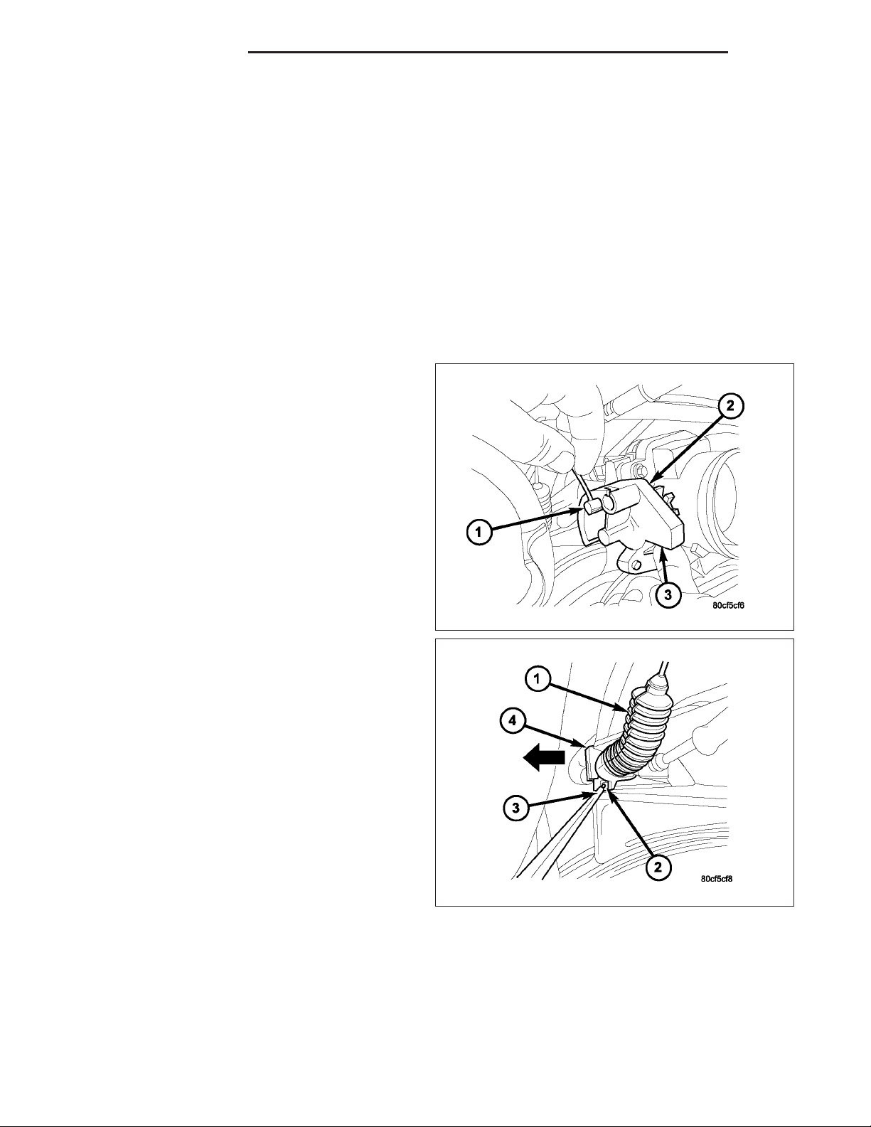
3. Hold throttle in wide open position. While held in
this position, slide throttle cable pin (1) from throttle
body bellcrank.
4. Using a pick or small screwdriver (3), press release
tab (2) to release plastic cable mount (4) from
bracket. Press on tab only enough to release
cable from bracket. If tab is pressed too much,
it will be broken. Slide plastic mount (4) towards
right side of vehicle to remove throttle cable from
throttle body bracket.
5. Using finger pressure only, disconnect servo cable connector (2) at throttle body bellcrank pin by pushing con-
Page 5

DR/DH SPEED CONTROL 8P - 5
nector off bellcrank pin towards front of vehicle. DO
NOT try to pull connector off perpendicular to
the bellcrank pin. Connector will be broken.
6. Slide speed control cable plastic mount (2) towards
right of vehicle to remove cable (3) from throttle
body bracket (1).
7. Remove servo cable from servo. Refer to Servo
Removal/Installation.
INSTALLATION
3.7L / 4.7L Gas
1. Install end of cable to speed control servo. Refer to Servo Removal/Installation.
2. Slide speed control cable plastic mount into throttle body bracket.
3. Install speed control cable connector onto throttle body bellcrank pin (push rearward to snap into location).
4. Slide throttle (accelerator) cable plastic mount into throttle body bracket. Continue sliding until cable release tab
is aligned to hole in throttle body mounting bracket.
5. While holding throttle to wide open position, place throttle cable pin into throttle body bellcrank.
6. Install air intake tube to top of throttle body.
7. Connect negative battery cable at battery.
8. Before starting engine, operate accelerator pedal to check for any binding.
Page 6

8P - 6 SPEED CONTROL DR/DH
SERVO
DESCRIPTION
A speed control servo is not used with any 5.7L V-8 engine, or with the 5.9L diesel engine.
The speed control servo is attached to the bottom of the battery tray.
The servo unit consists of a solenoid valve body, and a vacuum chamber. The solenoid valve body contains three
solenoids:
• Vacuum
• Vent
• Dump
The vacuum chamber contains a diaphragm with a cable attached to control the throttle linkage.
OPERATION
A speed control servo is not used with any 5.7L V-8 engine, or with the 5.9L diesel engine.
The following information applies only to vehicles equipped with a mechanical servo.
When/if a servo is used on gasoline powered vehicles, the Powertrain Control Module (PCM) controls the solenoid
valve body. The solenoid valve body controls the application and release of vacuum to the diaphragm of the vacuum
servo. The servo unit cannot be repaired and is serviced only as a complete assembly.
Power is supplied to the servo’s by the PCM through the brake switch. The PCM controls the ground path for the
vacuum and vent solenoids.
The dump solenoid is energized anytime it receives power. If power to the dump solenoid is interrupted, the solenoid dumps vacuum in the servo. This provides a safety backup to the vent and vacuum solenoids.
The vacuum and vent solenoids must be grounded at the PCM to operate. When the PCM grounds the vacuum
servo solenoid, the solenoid allows vacuum to enter the servo and pull open the throttle plate using the cable. When
the PCM breaks the ground, the solenoid closes and no more vacuum is allowed to enter the servo. The PCM also
operates the vent solenoid via ground. The vent solenoid opens and closes a passage to bleed or hold vacuum in
the servo as required.
The PCM duty cycles the vacuum and vent solenoids to maintain the set speed, or to accelerate and decelerate the
vehicle. To increase throttle opening, the PCM grounds the vacuum and vent solenoids. To decrease throttle opening, the PCM removes the grounds from the vacuum and vent solenoids. When the brake is released, if vehicle
speed exceeds 30 mph to resume, 35 mph to set, and the RES/ACCEL switch has been depressed, ground for the
vent and vacuum circuits is restored.
Page 7

DR/DH SPEED CONTROL 8P - 7
REMOVAL
The speed control servo assembly is attached to the
bottom of the battery tray (1).
1. Disconnect negative battery cable at battery (both
cables at both batteries if diesel).
2. To gain access to servo, remove plastic wheelhouse splash shield over left-front wheel.
3. Disconnect vacuum line (7) at servo.
4. Disconnect electrical connector (4) at servo.
5. Remove 3 servo mounting screws (5). Depending
on engine application, different sets of mounting
lugs (2) are used to support servo to battery tray.
While removing, note proper lugs.
6. Disconnect servo cable at throttle body. Refer to
Servo Cable Removal/Installation.
7. Remove 2 mounting nuts (1) holding servo cable
sleeve to bracket.
8. Pull speed control cable sleeve and servo away
from servo mounting bracket to expose cable
retaining clip (3) and remove clip. Note: The servo
mounting bracket displayed is a typical bracket and
may/may not be applicable to this model vehicle.
9. Remove servo (2) from mounting bracket. While
removing, note orientation of servo to bracket.
INSTALLATION
1. Position servo to mounting bracket.
2. Align hole in cable connector with hole in servo pin. Install cable-to-servo retaining clip.
3. Insert servo mounting studs through holes in servo mounting bracket.
4. Install 2 servo-to-mounting bracket nuts and tighten. Refer to torque specifications.
5. Position servo assembly to correct mounting lugs on battery tray and install 3 screws. Tighten 3 screws. Refer to
torque specifications.
6. Connect vacuum line at servo.
7. Connect electrical connector at servo.
8. Connect servo cable to throttle body. Refer to servo Cable Removal/Installation.
9. Install left-front wheel-well liner.
10. Connect negative battery cable to battery (connect both cables if diesel).
11. Before starting engine, operate accelerator pedal to check for any binding.
Page 8

8P - 8 SPEED CONTROL DR/DH
SWITCH
DESCRIPTION
Two separate switch pods operate the speed control system. The steering-wheel-mounted switches use multiplexed
circuits to provide inputs to the PCM (to the ECM for diesel) for ON, OFF, RESUME, ACCELERATE, SET, DECEL
and CANCEL modes. Refer to the owner’s manual for more information on speed control switch functions and setting procedures.
The individual switches cannot be repaired. If one switch fails, the entire switch module must be replaced.
Depending on engine control computer (JTEC having a 3– plug connector or NGC having a 4– plug connector), 2 types of switches are used. Both types of switches are internally and externally different. The
switch used with the NGC system has an attached pigtail lead. The switch used with the JTEC system does
not have an attached pigtail lead.
OPERATION
When speed control is selected by depressing the ON, OFF switch, the PCM (ECM for diesel) allows a set speed
to be stored in its RAM for speed control. To store a set speed, depress the SET switch while the vehicle is moving
at a speed between approximately 35 and 85 mph. In order for the speed control to engage, the brakes cannot be
applied, nor can the gear selector be indicating the transmission is in Park or Neutral.
The speed control can be disengaged manually by:
• Stepping on the brake pedal
• Depressing the OFF switch
• Depressing the CANCEL switch.
The speed control can be disengaged also by any of the following conditions:
• An indication of Park or Neutral (auto. trans.)
• The VSS signal increases at a rate of 10 mph per second (indicates that the co-efficient of friction between the
road surface and tires is extremely low)
• Depressing the clutch pedal (manual trans.).
• Excessive engine rpm (indicates that the transmission may be in a low gear)
• The VSS signal decreases at a rate of 10 mph per second (indicates that the vehicle may have decelerated at
an extremely high rate)
• If the actual speed is not within 20 mph of the set speed
The previous disengagement conditions are programmed for added safety.
Once the speed control has been disengaged, depressing the ACCEL switch restores the vehicle to the target
speed that was stored in the PCM’s RAM (ECM for diesel).
NOTE: Depressing the OFF switch will erase the set speed stored in the PCM’s/ECM’s RAM.
If, while the speed control is engaged, the driver wishes to increase vehicle speed, the PCM (ECM for diesel) is
programmed for an acceleration feature. With the ACCEL switch held closed, the vehicle accelerates slowly to the
desired speed. The new target speed is stored in the PCM’s/ECM’s RAM when the ACCEL switch is released. The
PCM/ECM also has a 9tap-up9 feature in which vehicle speed increases at a rate of approximately 2 mph for each
momentary switch activation of the ACCEL switch.
The PCM/ECM also provides a means to decelerate without disengaging speed control. To decelerate from an existing recorded target speed, depress and hold the COAST switch until the desired speed is reached. Then release the
switch. The ON, OFF switch operates two components: the PCM’s/ECM’s ON, OFF input, and the battery voltage to
the brake switch.
Page 9

DR/DH SPEED CONTROL 8P - 9
REMOVAL
Depending on engine control computer (JTEC having a 3–plug connector or 5.7L V-8 NGC having a
4–plug connector), 2 types of switches are used.
Both types of switches are internally and externally different. The switches used with the NGC
system have attached pigtail leads. The switch
used with the JTEC system does not have an
attached pigtail lead.
1. Remove switch mounting screw (2).,
2. Pull switch (2) from steering wheel.
3. Unplug electrical connector from switch , or, switch
pigtail wire harness from steering wheel wire harness (4) and remove switch.
INSTALLATION
1. Plug electrical connector into switch , or connect pigtail wire harness to steering wheel wire harness. Be sure
wires are not pinched.
2. Position switch to steering wheel.
3. Install switch mounting screw and tighten. Refer to torque specifications.
Page 10

8P - 10 SPEED CONTROL DR/DH
RESERVOIR-VACUUM
DESCRIPTION
The vacuum reservoir is a plastic storage tank connected to an engine vacuum source by vacuum lines. A vacuum
reservoir is not used with diesel engines or the 5.7L gas powered engine.
OPERATION
The vacuum reservoir is used to supply the vacuum needed to maintain proper speed control operation when
engine vacuum drops, such as in climbing a grade while driving. A one-way check valve is used in the vacuum line
between the reservoir and the vacuum source. This check valve is used to trap engine vacuum in the reservoir. On
certain vehicle applications, this reservoir is shared with the heating/air-conditioning system. The vacuum reservoir
cannot be repaired and must be replaced if faulty.
DIAGNOSIS AND TESTING
VACUUM RESERVOIR
1. Disconnect vacuum hose at speed control servo and install a vacuum gauge into the disconnected hose.
2. Start engine and observe gauge at idle. Vacuum gauge should read at least ten inches of mercury.
3. If vacuum is less than ten inches of mercury, determine source of leak. Check vacuum line to engine for leaks.
Also check actual engine intake manifold vacuum. If manifold vacuum does not meet this requirement, check for
poor engine performance and repair as necessary.
4. If vacuum line to engine is not leaking, check for leak at vacuum reservoir. To locate and gain access to reser-
voir, refer to Vacuum Reservoir Removal/Installation in this group. Disconnect vacuum line at reservoir and connect a hand-operated vacuum pump to reservoir fitting. Apply vacuum. Reservoir vacuum should not bleed off. If
vacuum is being lost, replace reservoir.
5. Verify operation of one-way check valve and check it for leaks. Certain models may be equipped with 2
check-valves.
a. Locate one-way check valve. The valve is located in vacuum line between vacuum reservoir and engine
vacuum source. Disconnect vacuum hoses (lines) at each end of valve.
b. Connect a hand-operated vacuum pump to reservoir end of check valve. Apply vacuum. Vacuum should not
bleed off. If vacuum is being lost, replace one-way check valve.
c. Connect a hand-operated vacuum pump to vacuum source end of check valve. Apply vacuum. Vacuum
should flow through valve. If vacuum is not flowing, replace one-way check valve. Seal the fitting at opposite
end of valve with a finger and apply vacuum. If vacuum will not hold, diaphragm within check valve has
ruptured. Replace valve.
Page 11

DR/DH SPEED CONTROL 8P - 11
REMOVAL
The vacuum reservoir (1) is located in the engine
compartment under the fresh air cowl grill panel.
1. Remove wiper blades and arms. Refer to Wiper
Arm Removal / Installation in the Wipers / Washers
section.
2. Remove fresh air cowl grill. Refer to Cowl Grill
Removal / Installation.
3. Disconnect vacuum line (2) at reservoir.
4. Remove 2 reservoir mounting nuts (3).
5. Remove reservoir from cowl.
INSTALLATION
1. Position reservoir onto 2 weld studs.
2. Install 2 mounting nuts and tighten. Refer to torque specifications.
3. Connect vacuum line to reservoir fitting.
4. Install cowl grill. Refer to Cowl Grill Removal / Installation.
5. Install wiper arms / blades. Refer to Wiper Arm Removal / Installation.
Page 12

 Loading...