

Dodge SO-O216A Series Installation Instructions Manual
f I
~ I
;
~
~
i
j
~
£j:i'-; , ,,"
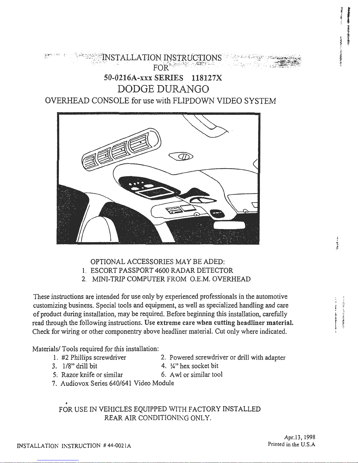
SO-O216A-xxx SERIES 118127X
DODGEDURANGO
OVERHEAD CONSOLE for use with FLIPDOWN VIDEO SYSTEM
~
OPTIONAL ACCESSORIES MA y BE ADED:
ESCORT PASSPORT 4600 RADAR DETECTOR
MINI- TRIP COMPUTER FROM O.E.M. OVERHEAD
1
2
These instructions are intended for use only by experienced professionals in the automotive
customizing business. Special tools and equipment, as well as specialized handling and care
of product during installation, may be required. Before beginning this installation, carefully
read through the following instructions. Use extreme care when cutting headliner material.
Check for wiring or other componentry above headliner material. Cut only where indicated.
Materials/ Tools required for this installation:
I. #2 Phillips screwdriver 2. Powered screwdriver or drill with adapter
3. 1/8" drill bit 4. ~" hex socket bit
5; Razor knife or similar 6. A wl or similar tool
7. Audiovox Series 640/641 Video Module
,
FOR USE IN VEHICLES EQUIPPED WITH FACTORY INSTALLED
REAR AIR CONDITIONING ONL Y.
Apr.13,1998
Printed in the U.S.A
INSTALLATION I;,\,STRUCTION # 44-0021A
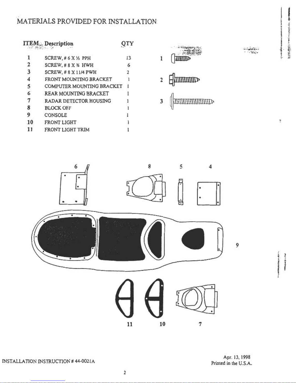
MA TERIALS PROVIDED FOR INST ALLA TION
,gTYlrEMi~,pe~cription
..;!~",;;c..c;, ..
~.
,~;.:~~':~,;;
" ,,-';;;c.:,;
[
~
~
.
.
i
{
I
.
~!
t
SCREW, # 6 X Y2 PPH 13
SCREW,#8X* HWH 6
SCREW, # 8 X 11/4 PWH 2
FRONT MOUNTING BRACKET 1
COMPUTER MOUNTING BRACKET I
REAR MOUNTING BRACKET I
RADAR DETECTOR HOUSING I
BLOCK OFF I
CONSOLE I
FRONT LIGHT I
FRONT LIGHT TRIM I
1
1
2
3
4
5
6
7
8
9
10
11
2
3
"
8
5
4
~
D
9
~
s
l
i
~
c
;.
I!:
i.
10
7
11
Apr. 13, 1998
Printed in the U.S.A.
INSTALLATION INSTRUCTION # 44-0021A
2
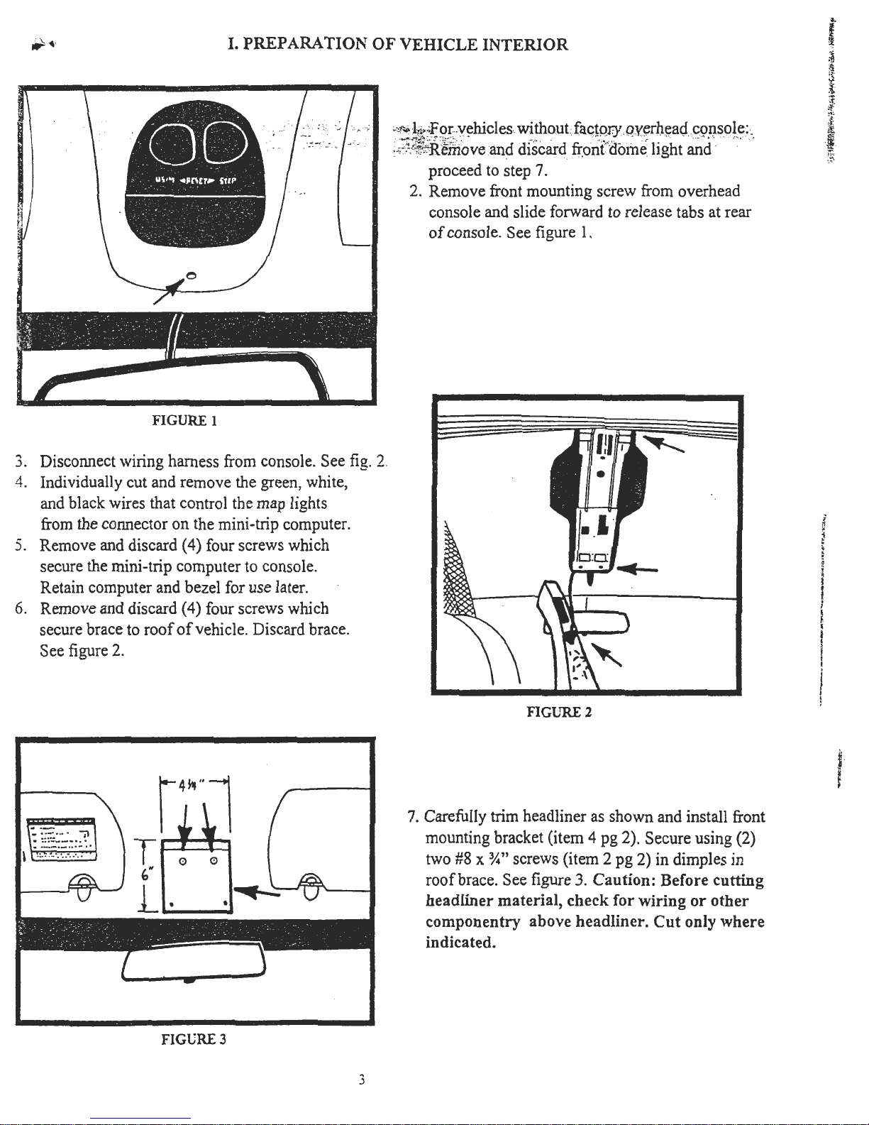
I. PREPARATION OF VEHICLE INTERIOR
.""4.'
..
~
({
~
$
"'
~
*
;t
~
,;
,J:
if.
,
,;;::.:!~emoveand discard fr.on(dOln~ light and
proceed to step 7.
2. Remove front mounting screw from overhead
console and slide forward to release tabs at rear
of console. See figure 1.
I
0
/
/
FIGURE 1
3. Disconnect wiring harness from console. See fig. 2
4. Individually cut and remove the green, white,
and black wires that control the map lights
from the connector on the mini-trip computer.
5. Remove and discard (4) four screws which
secure the mini-trip computer to console.
Retain computer and bezel for use later.
6. Remove and discard (4) four screws which
secure brace to roof of vehicle. Discard brace.
See figure 2.
.
.
,
~
~
2
.
.
t
I
~
~
f
f
i
I
[
I
!
~
-
-\:
FIGLTRE 2
7. Carefully trim headliner as shown and install front
mounting bracket (item 4 pg 2). Secure using (2)
two #8 x ~" screws (item 2 pg 2) in dimples in
roof brace. See figure 3. Caution: Before cutting
headliner material, check for wiring or other
componentry above headliner. Cut only where
indicated.
~
~
v
FIGURE 3
3
 Loading...