

Page 1

Factory Workshop Manual
Dodge
Ram Srt-10 Pickup
V10-505 8.3L (2004)
Anonymous
1st January 2018
Make
Model
Engine and year
This manual was submitted by
Date
Page 2
Dodge Ram Srt-10 Pickup Workshop Manual (V10-505 8.3L (2004))
Dodge Workshop Manuals > Relays and Modules > Relays and Modules - Accessories and Optional Equipment > Alarm
Module, (Vehicle Antitheft) > Component Information > Description and Operation
Alarm Module: Description and Operation
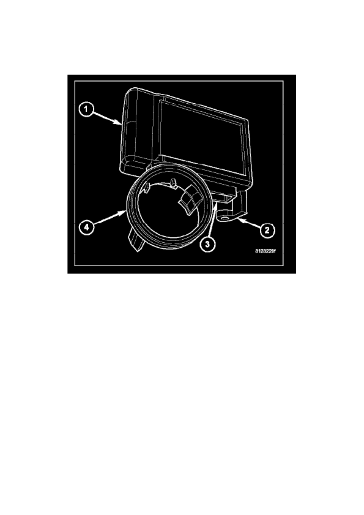
The Sentry Key Immobilizer Module (SKIM) (1) is the primary component of the Sentry Key
Immobilizer System (SKIS). This module contains a Radio Frequency (RF) transceiver and a
central processing unit, which includes the Sentry Key Immobilizer System (SKIS) program logic.
The SKIM is located on the right side of the steering column, near the ignition lock cylinder housing
and is concealed beneath the steering column shrouds. The molded black plastic housing for the
SKIM has an integral molded plastic halo-like antenna ring (4) that extends from the bottom. When
the SKIM is properly installed on the steering column, the antenna ring is oriented around the
circumference of the ignition lock cylinder housing.
A single integral connector receptacle (3) is located just behind the antenna ring on the bottom of
the SKIM housing. An integral molded plastic mounting tab (2) on the rear corner of the SKIM
housing has a hole in the center through which a screw passes to secure the unit to the steering
column. The SKIM is connected to the vehicle electrical system through a single take out and
connector of the instrument panel wire harness.
The Sentry Key Immobilizer Module (SKIM) transmits Radio Frequency (RF) signals to, and
receives RF signals from the Sentry Key transponder through a tuned antenna enclosed within the
molded plastic antenna ring. If this antenna ring is not mounted properly around the ignition lock
cylinder housing, communication problems between the SKIM and the transponder may arise.
These communication problems will result in Sentry Key transponder-related faults. The SKIM also
communicates over the Programmable Communications Interface (PCI) data bus with the
Powertrain Control Module (PCM) for gasoline engines or the Engine Control Module (ECM) for
diesel engines, the ElectroMechanical Instrument Cluster (EMIC) and/or a diagnostic scan tool.
Page 3

The SKIM and the PCM/ECM both use software that includes a rolling code algorithm strategy,
which helps to reduce the possibility of unauthorized Sentry Key Immobilizer System (SKIS)
disarming. The rolling code algorithm ensures security by preventing an override of the SKIS
through the unauthorized substitution of the SKIM or the PCM/ECM. However, the use of this
strategy also means that replacement of either the SKIM or the PCM/ECM units will require a
system initialization procedure to restore system operation.
The SKIM retains in memory the ID numbers of any Sentry Key transponder that is programmed
into it. A maximum of eight Sentry Key transponders can be programmed into the SKIM. For added
system security, each SKIM is programmed with a unique Secret Key code. This code is stored in
memory, sent over the PCI data bus to the PCM or ECM, and is encoded to the transponder of
every Sentry Key that is programmed into the SKIM. Therefore, the Secret Key code is a common
element that is found in every component of the SKIS.
Another security code called a PIN, is used to gain access to the SKIM Secured Access Mode. The
Secured Access Mode is required during service to perform the SKIS initialization and Sentry Key
transponder programming procedures. The SKIM also stores the Vehicle Identification Number
(VIN) in its memory, which it learns through a PCI data bus message from the PCM or ECM during
SKIS initialization.
In the event that a SKIM replacement is required, the Secret Key code can be transferred to the
new SKIM from the PCM using a diagnostic scan tool and the SKIS initialization procedure. Proper
completion of the SKIS initialization will allow the existing Sentry Keys to be programmed into the
new SKIM so that new keys will not be required. In the event that the original Secret Key code
cannot be recovered, SKIM replacement will also require new Sentry Keys. The diagnostic scan
tool will alert the technician during the SKIS initialization procedure if new Sentry Keys are
required.
When the ignition switch is turned to the On or Start positions, the SKIM transmits an RF signal to
excite the transponder in the ignition key. The SKIM then listens for a return RF signal from the
transponder. If the SKIM receives an RF signal with a valid "Secret Key" and transponder
identification codes, the SKIM sends a "valid key" message to the PCM/ECM over the PCI bus. If
the SKIM receives an invalid RF signal or no response, it sends "invalid key" messages to the
PCM/ECM. The PCM/ECM will enable or disable engine operation based upon the status of the
SKIM messages. It is important to note that the default condition in the PCM or ECM is an invalid
key. Therefore, if no message is received from the SKIM by the PCM or ECM, the engine will be
disabled and the vehicle immobilized after two seconds of running.
Page 4

Dodge Ram Srt-10 Pickup Workshop Manual (V10-505 8.3L (2004))
Dodge Workshop Manuals > Relays and Modules > Relays and Modules - Accessories and Optional Equipment > Alarm
Module, (Vehicle Antitheft) > Component Information > Description and Operation > Page 7
Page 5

The SKIM also sends electronic messages to the EMIC which control the VTSS indicator. The
SKIM sends messages to the EMIC to turn the indicator on for about three seconds when the
ignition switch is turned to the On position as a bulb test. After completion of the bulb test, the
SKIM sends bus messages to keep the indicator off for a duration of about one second. Then the
SKIM sends messages to turn the indicator on or off based upon the results of the SKIS self-tests.
If the VTSS indicator comes on and stays on after the bulb test, it indicates that the SKIM has
detected a system malfunction and/or that the SKIS has become inoperative.
If the SKIM detects an invalid key when the ignition switch is turned to the On position, it sends
messages to flash the VTSS indicator. The SKIM can also send messages to flash the indicator
and to generate a single audible chime whenever the Customer Learn programming mode is being
utilized.
The SKIS will store fault information in the form of Diagnostic Trouble Codes (DTC's) in SKIM
memory if a system malfunction is detected. For diagnosis or initialization of the SKIM and the
PCM/ECM, a diagnostic scan tool is required.
Page 6
Dodge Ram Srt-10 Pickup Workshop Manual (V10-505 8.3L (2004))
Dodge Workshop Manuals > Relays and Modules > Relays and Modules - Accessories and Optional Equipment > Alarm
Module, (Vehicle Antitheft) > Component Information > Description and Operation > Page 8
Page 7

Alarm Module: Service and Repair
WARNING: TO AVOID PERSONAL INJURY OR DEATH, ON VEHICLES EQUIPPED WITH
AIRBAGS, DISABLE THE SUPPLEMENTAL RESTRAINT SYSTEM BEFORE ATTEMPTING ANY
STEERING WHEEL, STEERING COLUMN, AIRBAG, SEAT BELT TENSIONER, IMPACT
SENSOR, OR INSTRUMENT PANEL COMPONENT DIAGNOSIS OR SERVICE. DISCONNECT
AND ISOLATE THE BATTERY NEGATIVE (GROUND) CABLE, THEN WAIT TWO MINUTES FOR
THE SYSTEM CAPACITOR TO DISCHARGE BEFORE PERFORMING FURTHER DIAGNOSIS
OR SERVICE. THIS IS THE ONLY SURE WAY TO DISABLE THE SUPPLEMENTAL RESTRAINT
SYSTEM. FAILURE TO TAKE THE PROPER PRECAUTIONS COULD RESULT IN ACCIDENTAL
AIRBAG DEPLOYMENT.
REMOVAL
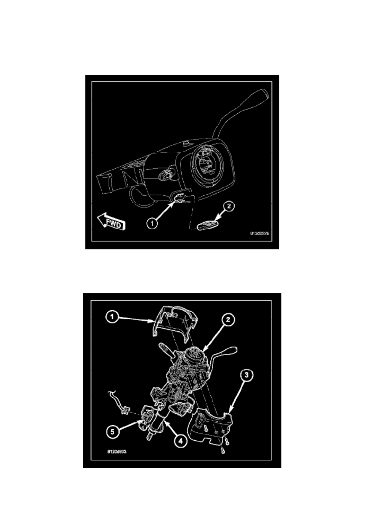
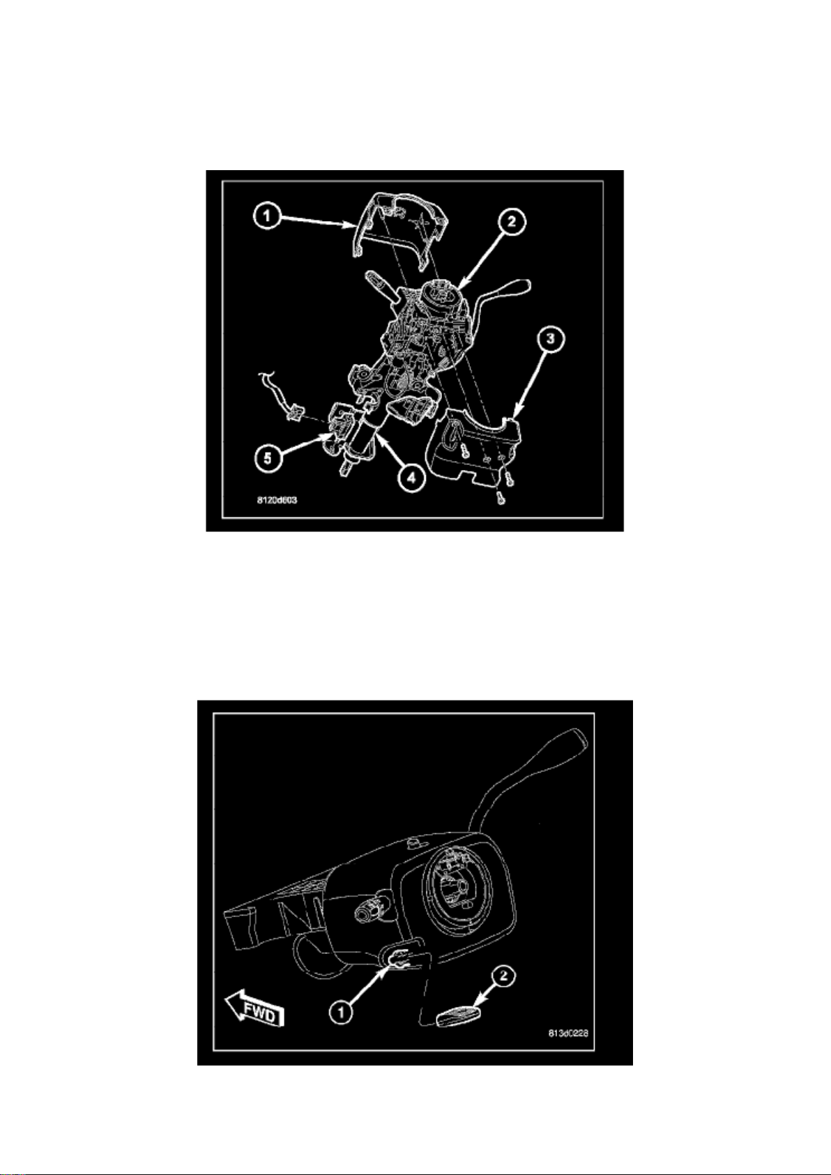
1. Disconnect and isolate the battery negative cable. 2. Grasp the tilt steering column knob (2)
firmly and pull it straight rearward to remove it from the tilt adjuster lever (1) on the left side of the
column.
3. From below the steering column, remove the two outboard screws that secure the upper column
shroud (1) to the lower shroud (3). 4. Using hand pressure, push inward on both sides of the upper
shroud above the parting line of the lower shroud to release the snap features that
secure the two shroud halves to each other.
5. Remove the upper shroud from the lower shroud and the steering column. 6. Remove the one
center screw that secures the lower shroud to the steering column (4). 7. Remove the lower shroud
from the steering column.
Page 8
Dodge Ram Srt-10 Pickup Workshop Manual (V10-505 8.3L (2004))
Dodge Workshop Manuals > Relays and Modules > Relays and Modules - Accessories and Optional Equipment > Alarm
Module, (Vehicle Antitheft) > Component Information > Description and Operation > Page 9
Page 9

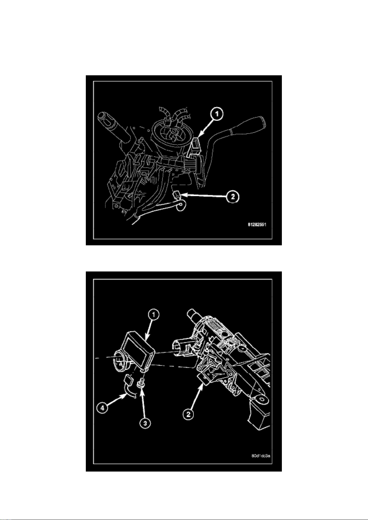
8. Disconnect the wire harness connector (2) from the Sentry Key Immobilizer Module (SKIM) (1).
9. Remove the screw (3) that secures the SKIM (1) to the steering column (2).
10. Disengage the antenna ring from around the ignition lock cylinder housing and remove the
SKIM.
INSTALLATION
Page 10
Dodge Ram Srt-10 Pickup Workshop Manual (V10-505 8.3L (2004))
Dodge Workshop Manuals > Relays and Modules > Relays and Modules - Accessories and Optional Equipment > Alarm
Module, (Vehicle Antitheft) > Component Information > Description and Operation > Page 10
Page 11

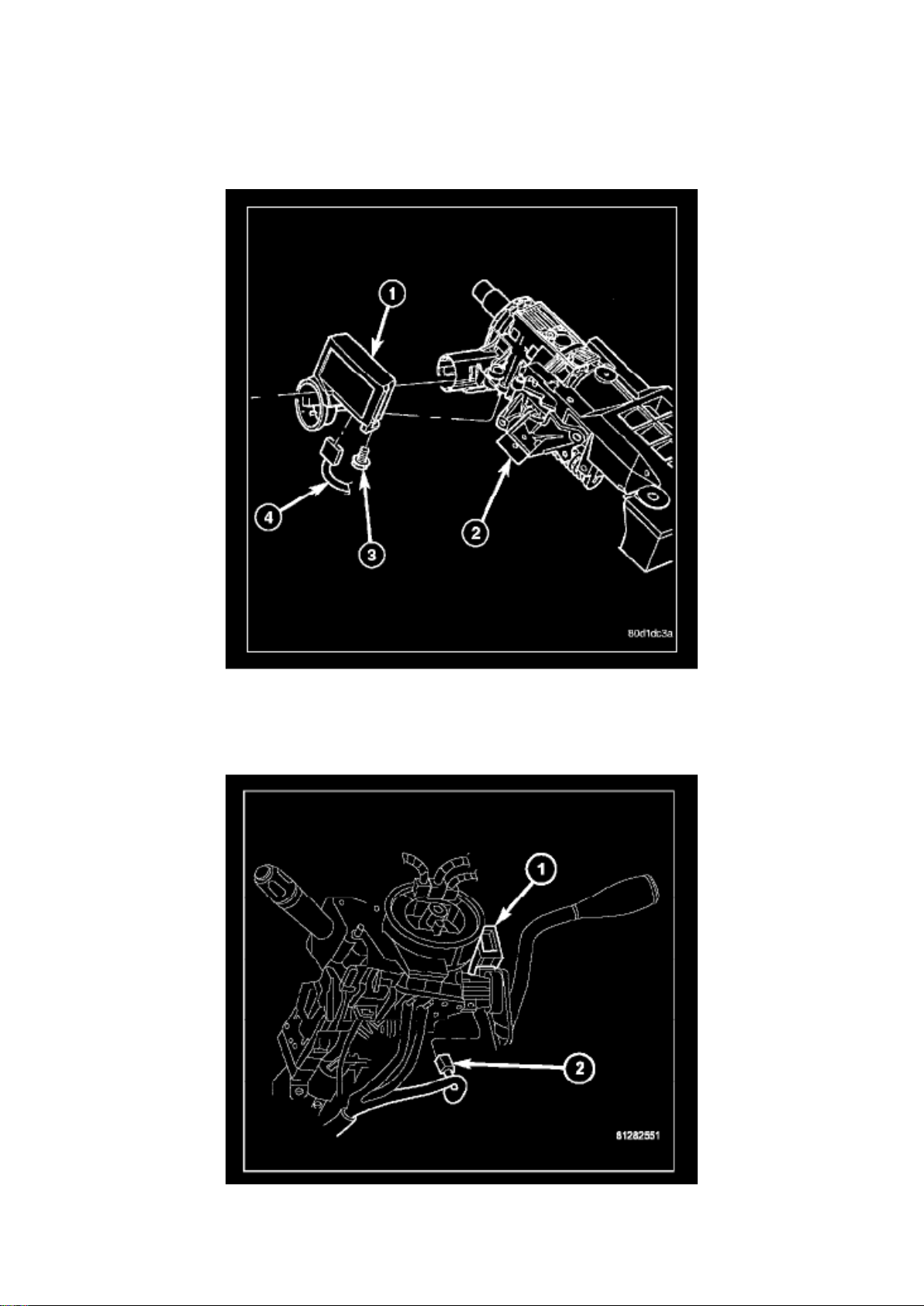
1. Position the Sentry Key Immobilizer Module (SKIM) (1) onto the steering column (2) with the
antenna ring oriented around the ignition lock
cylinder housing.
2. Install and tighten the screw (3) that secures the SKIM to the steering column housing. Tighten
the screw to 2 N.m (20 in.lbs.).
3. Reconnect the wire harness connector (2) to the SKIM (1).
Page 12
Dodge Ram Srt-10 Pickup Workshop Manual (V10-505 8.3L (2004))
Dodge Workshop Manuals > Relays and Modules > Relays and Modules - Accessories and Optional Equipment > Alarm
Module, (Vehicle Antitheft) > Component Information > Description and Operation > Page 11
Page 13

4. Position the lower shroud (3) onto the steering column (4). 5. From below the steering column,
install and tighten the one center screw that secures the lower shroud to the steering column.
Tighten the screw to
2 N.m (20 in.lbs.)
6. Position the upper shroud (1) onto the steering column over the lower shroud. On vehicles
equipped with an automatic transmission, be certain to
engage the gearshift lever gap hider into the opening in the right side of both shroud halves.
7. Align the snap features on the upper shroud with the receptacles in the lower shroud and apply
hand pressure to snap them together. 8. Install and tighten the two outboard screws that secure the
upper shroud to the lower shroud. Tighten the screws to 2 N.m (20 in.lbs.)
9. Align the tilt steering column knob (2) with the tilt adjuster lever (1) on the left side of the steering
column and use hand pressure to snap it back
into place.
10. Reconnect the battery negative cable.
NOTE: If the SKIM is replaced with a new unit, a diagnostic scan tool MUST be used to initialize
the new SKIM and to program at least two Sentry Key transponders before the vehicle can be
operated.
Page 14
Dodge Ram Srt-10 Pickup Workshop Manual (V10-505 8.3L (2004))
Dodge Workshop Manuals > Relays and Modules > Relays and Modules - Accessories and Optional Equipment > Keyless
Entry Module > Component Information > Locations
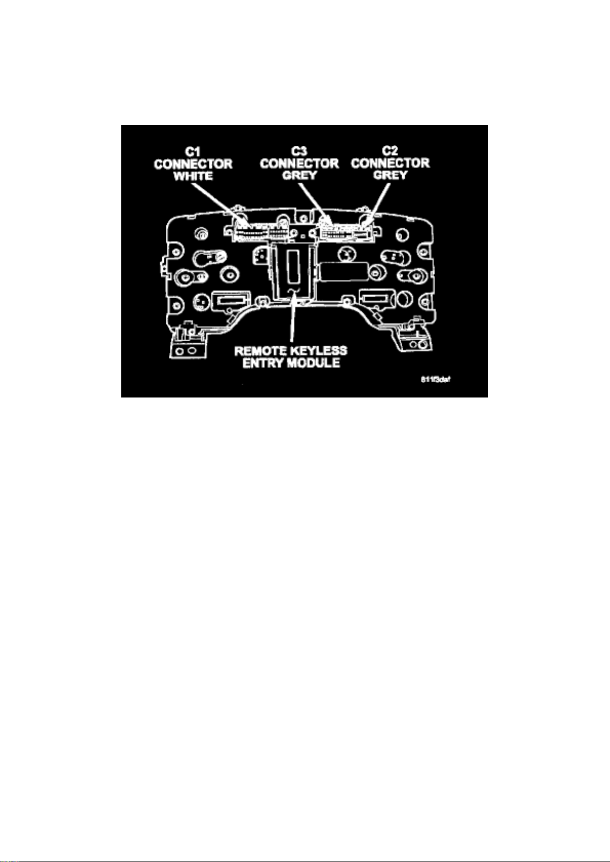
RKE Module
Page 15
Dodge Ram Srt-10 Pickup Workshop Manual (V10-505 8.3L (2004))
Dodge Workshop Manuals > Relays and Modules > Relays and Modules - Accessories and Optional Equipment > Keyless
Entry Module > Component Information > Locations > Page 15
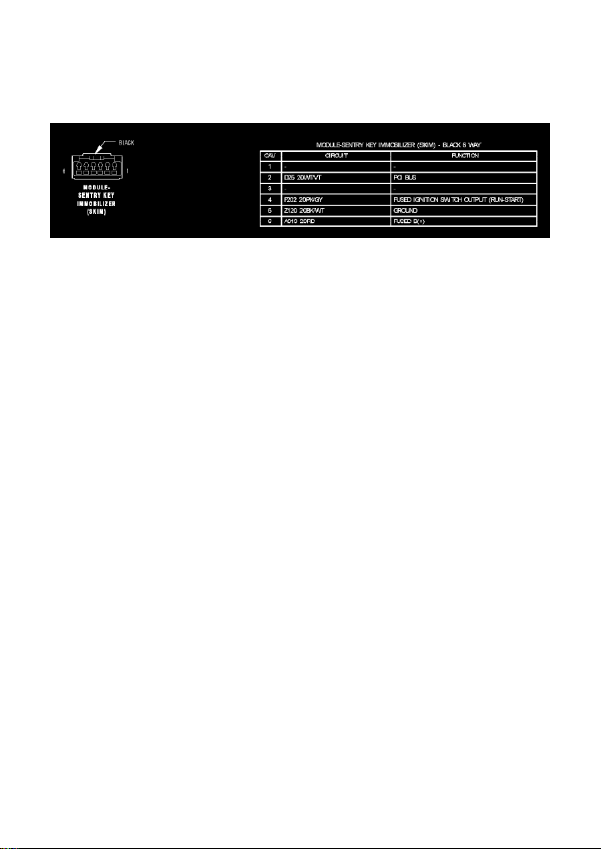
Module-Sentry Key Immobilizer (SKIM)
Page 16

Dodge Ram Srt-10 Pickup Workshop Manual (V10-505 8.3L (2004))
Dodge Workshop Manuals > Relays and Modules > Relays and Modules - Accessories and Optional Equipment > Keyless
Entry Module > Component Information > Locations > Page 16
Page 17

Keyless Entry Module: Description and Operation
When an RKE lock message is sent to the instrument cluster, the instrument cluster actuates the
door locks, the interior lighting is turned off, the horn chirps (if this feature is enabled), the park
lamps flash (if this feature is enabled) and, if the vehicle is so equipped, the Vehicle Theft Security
System (VTSS) is armed. When an RKE unlock message is sent to the instrument cluster, the
instrument cluster actuates the driver side front door (or all doors if this feature is enabled) unlock,
the interior lighting is turned on and, if the vehicle is so equipped, the VTSS is disarmed.
When an RKE panic message is sent to the instrument cluster, the instrument cluster actuates the
driver side front door (or all doors if this feature is enabled) unlock, the interior lighting is turned on
and, if the vehicle is so equipped, the VTSS is disarmed. The panic message will also cause the
exterior lamps (including the headlights) to flash, and the horn to sound for about three minutes, or
until a second panic message is sent to the instrument cluster. A vehicle speed of about 25.7
kilometers-per-hour (15 miles-per-hour) will also cancel the panic event.
Whenever the vehicle battery power is interrupted, the Remote Keyless Module (RKE) Module will
retain all vehicle access codes in its memory. When replacing or adding a key fob transmitter
(maximum of 4) a scan tool is required to program the RKE Module to accept the new Vehicle
Access Code if a customer owned transmitter is not available.
Page 18

Dodge Ram Srt-10 Pickup Workshop Manual (V10-505 8.3L (2004))
Dodge Workshop Manuals > Relays and Modules > Relays and Modules - Accessories and Optional Equipment > Keyless
Entry Module > Component Information > Locations > Page 17
Page 19

Keyless Entry Module: Testing and Inspection
The most reliable, efficient, and accurate means to diagnose the power lock system requires the
use of a scan tool and the proper Diagnostic Procedures information.
Page 20
Dodge Ram Srt-10 Pickup Workshop Manual (V10-505 8.3L (2004))
Dodge Workshop Manuals > Relays and Modules > Relays and Modules - Accessories and Optional Equipment > Keyless
Entry Module > Component Information > Locations > Page 18
Page 21

Keyless Entry Module: Service and Repair
REMOVAL
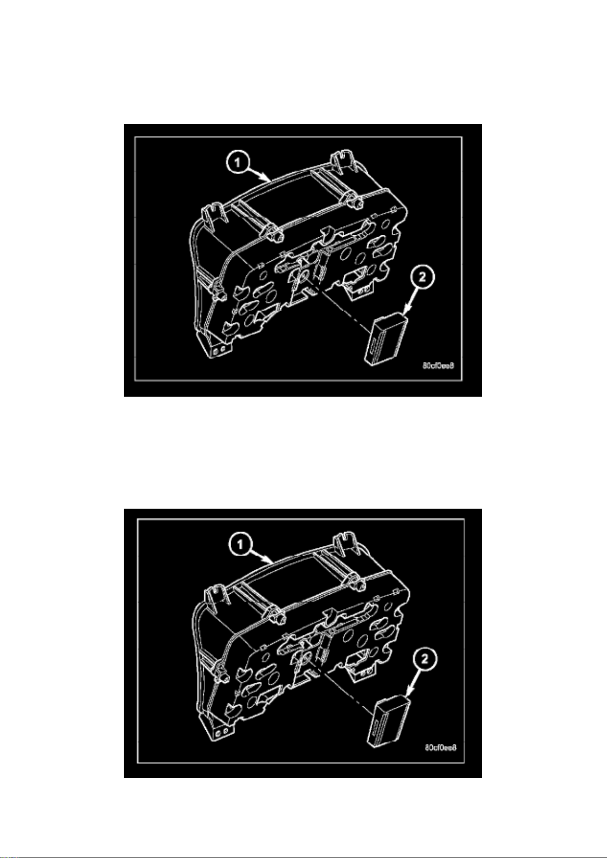
1. Disconnect and isolate the battery negative cable. 2. Remove the instrument cluster. 3. Remove
remote keyless entry module (2) from instrument cluster (1).
INSTALLATION
1. Install remote keyless entry module (2) to instrument cluster (1). 2. Install instrument cluster. 3.
Connect the battery negative cable.
Page 22
Dodge Ram Srt-10 Pickup Workshop Manual (V10-505 8.3L (2004))
Dodge Workshop Manuals > Relays and Modules > Relays and Modules - Accessories and Optional Equipment > Voice
Activation Module > Component Information > Locations
Page 23

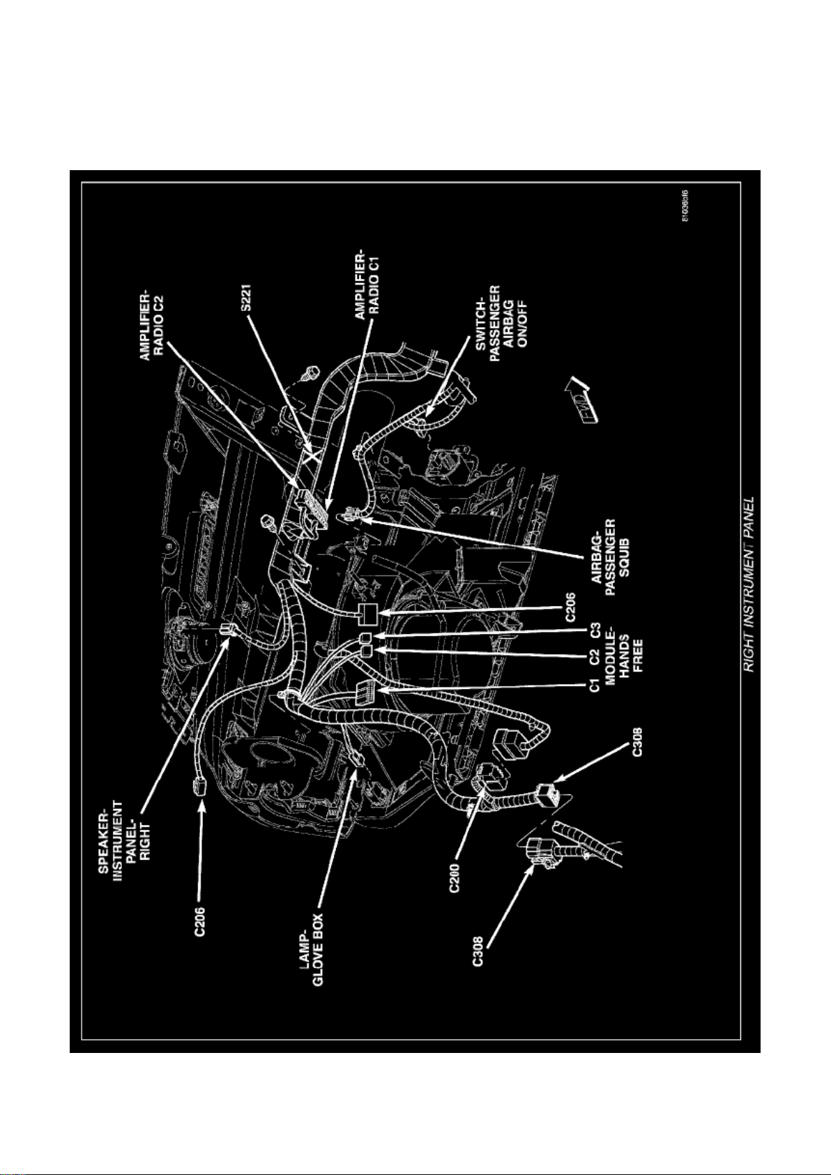
Right Instrument Panel
Page 24
Dodge Ram Srt-10 Pickup Workshop Manual (V10-505 8.3L (2004))
Dodge Workshop Manuals > Relays and Modules > Relays and Modules - Accessories and Optional Equipment > Voice
Activation Module > Component Information > Locations > Page 22
Page 25

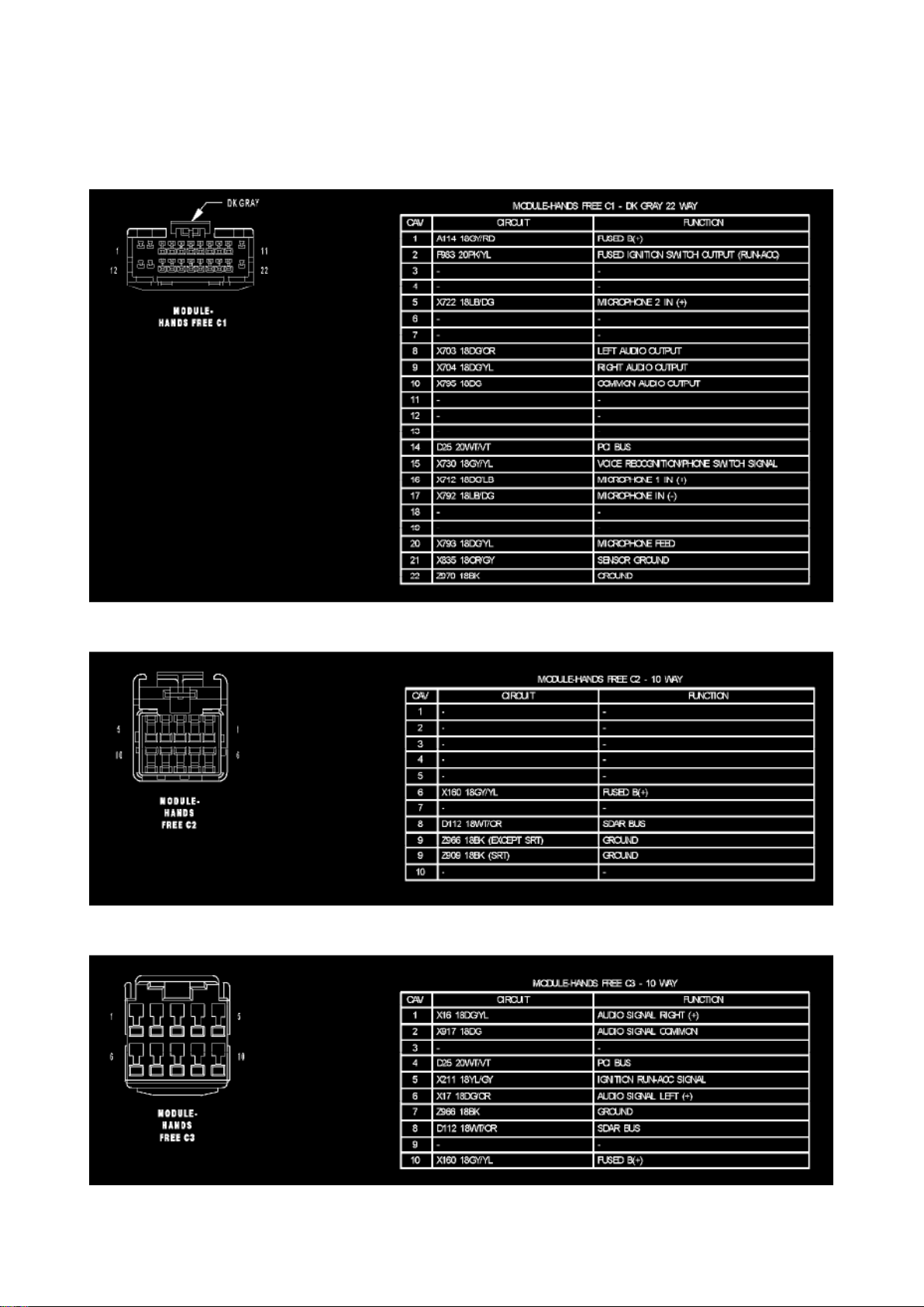
Voice Activation Module: Diagrams
Module-Hands Free C1
Module-Hands Free C2
Module-Hands Free C3
Page 26
Dodge Ram Srt-10 Pickup Workshop Manual (V10-505 8.3L (2004))
Dodge Workshop Manuals > Relays and Modules > Relays and Modules - Accessories and Optional Equipment > Voice
Activation Module > Component Information > Locations > Page 23
Page 27

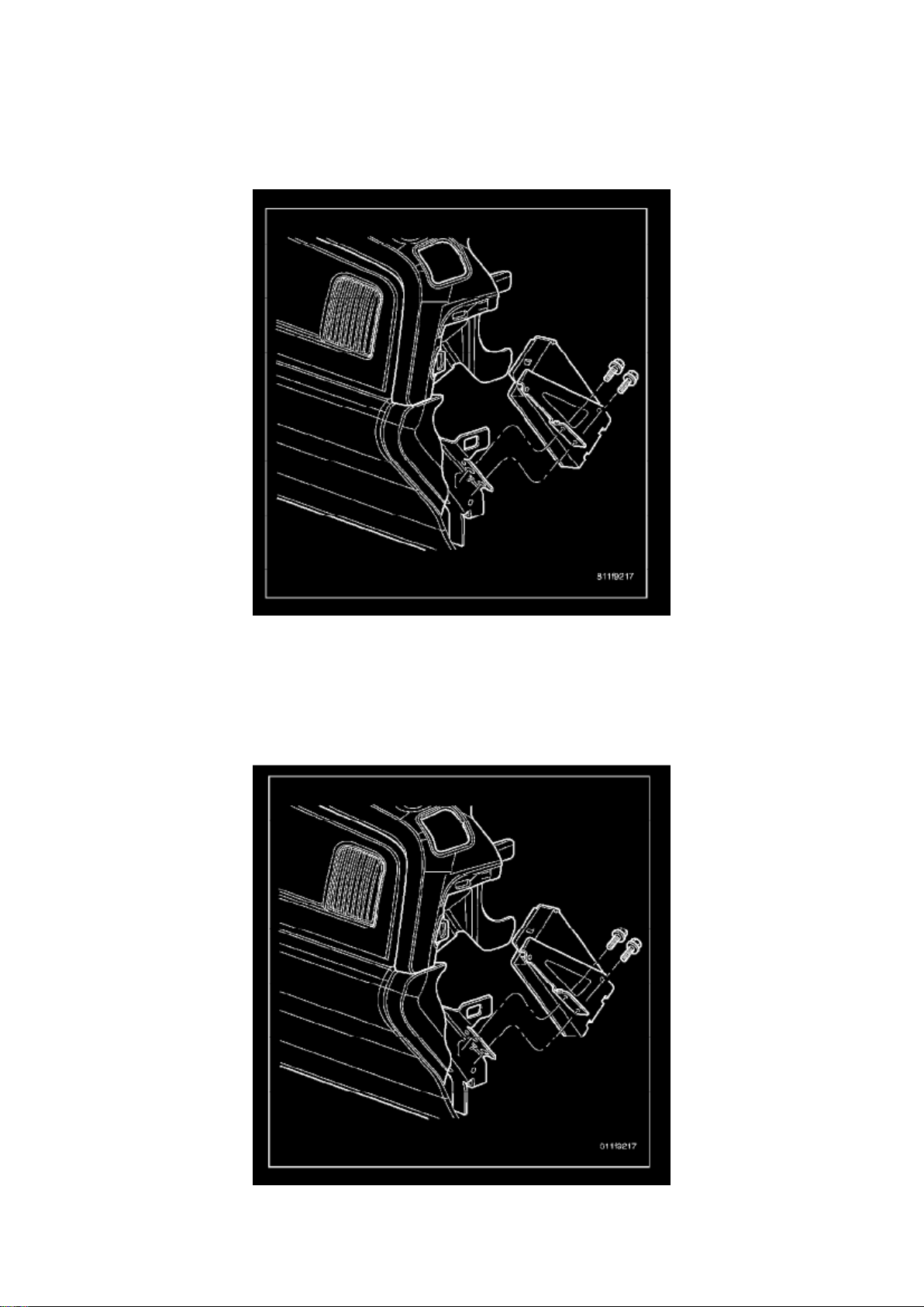
Voice Activation Module: Service and Repair
REMOVAL
1. Disconnect and isolate the battery negative cable. 2. Remove the instrument panel right side end
cap. 3. Remove the mounting fasteners. 4. Disconnect the electrical harness connector and
remove module.
INSTALLATION
1. Connect the electrical harness connector and position module. 2. Install and tighten the
mounting fasteners. 3. Install the instrument panel right side end cap. 4. Connect battery negative
cable.
Page 28
Dodge Ram Srt-10 Pickup Workshop Manual (V10-505 8.3L (2004))
Dodge Workshop Manuals > Relays and Modules > Relays and Modules - Body and Frame > Heated Mirror Relay >
Component Information > Locations
Page 29

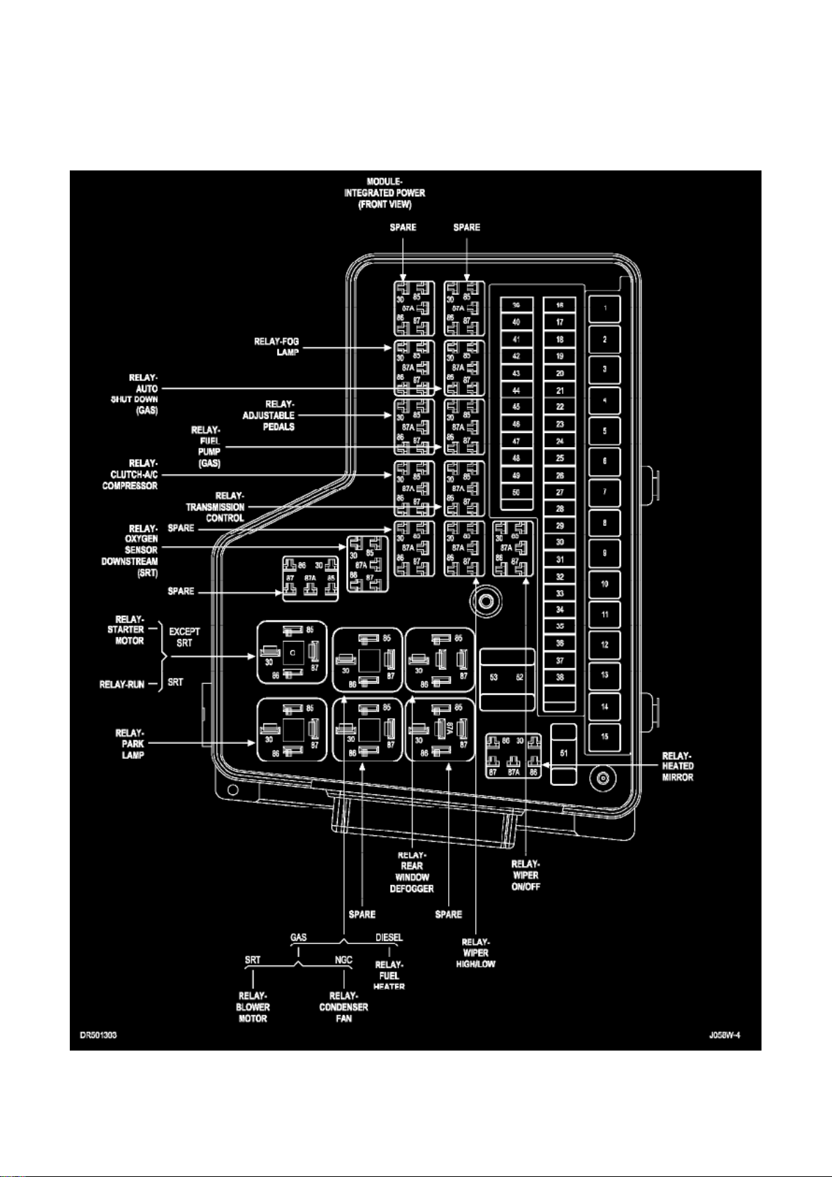
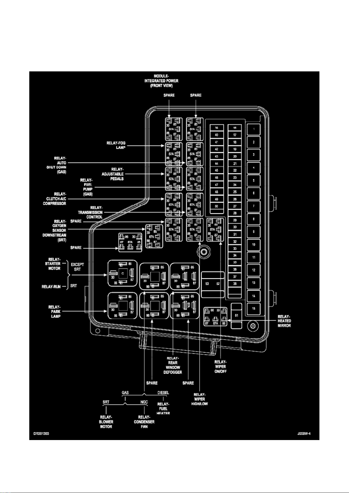
Module - Integrated Power (Front View)
Page 30
Dodge Ram Srt-10 Pickup Workshop Manual (V10-505 8.3L (2004))
Dodge Workshop Manuals > Relays and Modules > Relays and Modules - Body and Frame > Heated Mirror Relay >
Component Information > Locations > Page 28
Heated Mirror Relay: Description and Operation
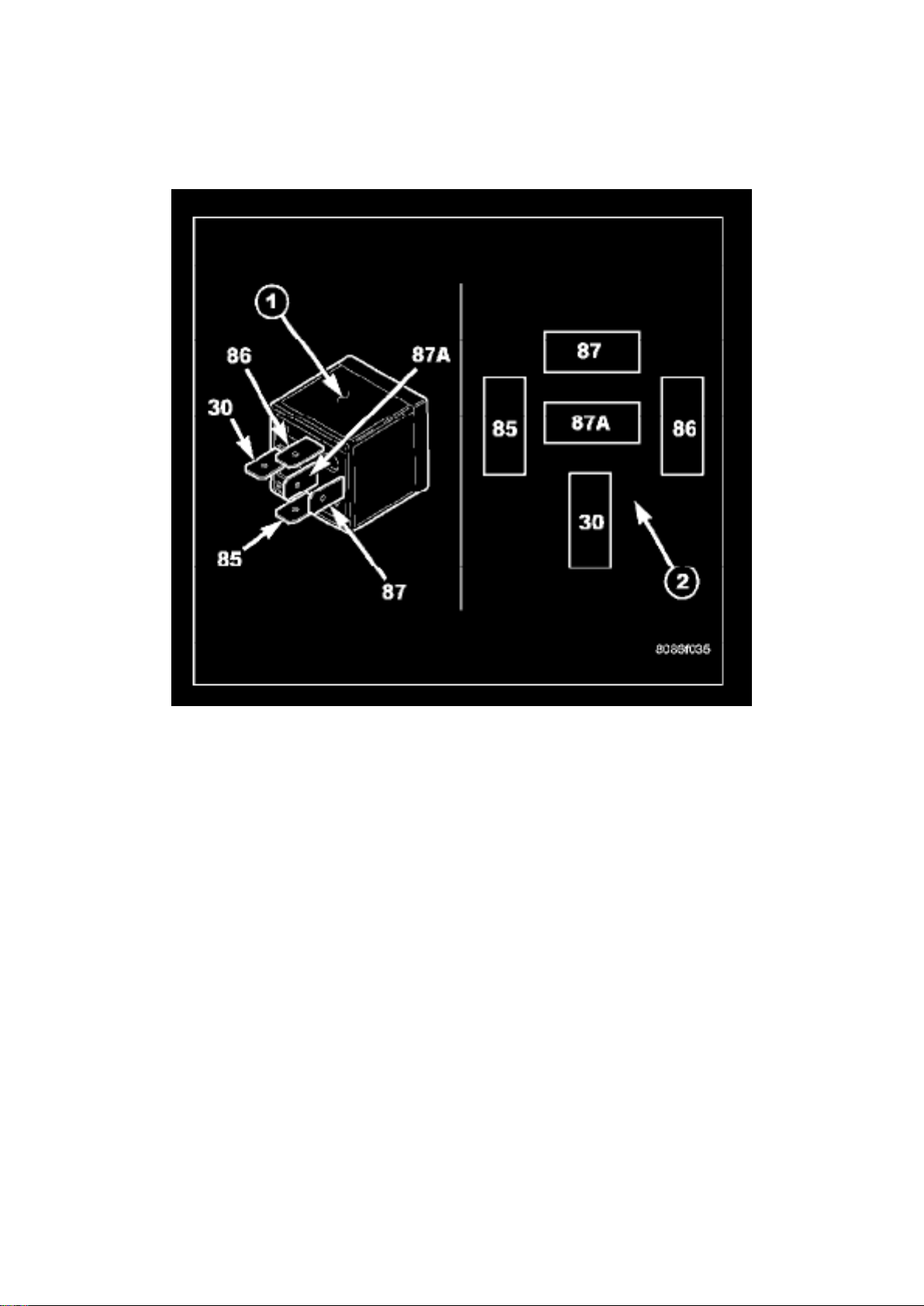
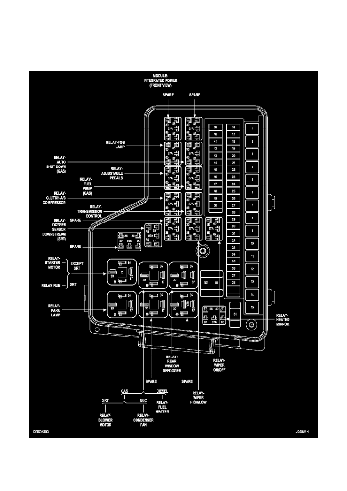
The heated mirror relay (1) is a International Standards Organization (ISO)-type relay. Relays
conforming to the ISO specifications have common physical dimensions, current capacities,
terminal functions and patterns (2). The heated mirror relay is a electromechanical device that
switches battery current through a fuse in the integrated power module (IPM) to the outside rear
view mirror heating grids. The heated mirror relay is energized when the relay coil is provided a
ground path by the control circuitry within the A/C-heater control.
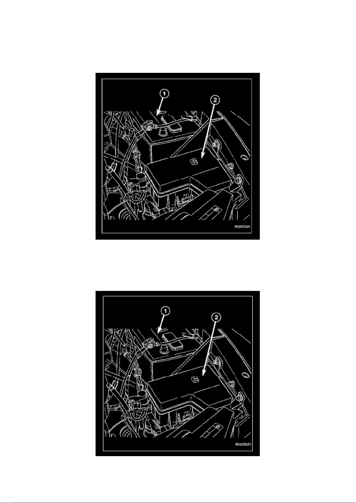
The heated mirror relay is located in the IPM in the engine compartment.
The ISO-standard heated mirror relay is an electromechanical switch that uses a low current input
controlled by the A/C-heater control to control the high current output to the outside rear view mirror
heating grids. The movable, common feed relay contact is held against the fixed, normally closed
relay contact by spring pressure. When the electromagnetic relay coil is energized, it draws the
movable common feed relay contact away from the fixed, normally closed relay contact and, holds
it against the fixed, normally open relay contact. This action allows high current to flow to the
outside rear view mirror heating grids.
When the relay coil is de-energized, spring pressure returns the movable relay contact back
against the fixed, normally closed contact point. The resistor or diode is connected in parallel with
the relay coil, and helps to dissipate voltage spikes and electromagnetic interference that can be
generated as the electromagnetic field of the relay coil collapses.
Page 31

The heated mirror relay terminals are connected to the vehicle electrical system through a
receptacle in the integrated power module (IPM). The inputs and outputs of the heated mirror relay
include:
- Terminal (30) receives fused battery current at all times.
- Terminal (86) receives a ground through the defogger relay control circuit only when the
A/C-heater control electronically pulls the circuit to ground.
- Terminal (85) receives fused battery current through an ignition switch output circuit only when
the ignition switch is in the Run position.
- Terminal (87) provides battery current to the heated outside rear view mirror grids through the
heated mirror relay output circuit only when the heated mirror relay coil is energized.
- Terminal (87A) is not connected to any circuit in this application, but provides a battery current
output only when the heated mirror relay coil is de-energized.
The heated mirror relay cannot be repaired and, if faulty or damaged, it must be replaced. Refer to
the appropriate wiring information for diagnosis and testing of the ISO-standard relay and for
complete heated mirror system wiring diagrams.
Page 32
Dodge Ram Srt-10 Pickup Workshop Manual (V10-505 8.3L (2004))
Dodge Workshop Manuals > Relays and Modules > Relays and Modules - Body and Frame > Heated Mirror Relay >
Component Information > Locations > Page 29
Page 33

Heated Mirror Relay: Service and Repair
NOTE: Refer to the fuse and relay layout map on the inside of the IPM cover for heated mirror relay
location.
REMOVAL
1. Disconnect and isolate the negative battery cable (1). 2. Remove the cover from the integrated
power module (IPM) (2) located in the engine compartment. 3. Remove the heated mirror relay
from the IPM.
INSTALLATION
1. Position the heated mirror relay into the proper receptacle of the integrated power module (IPM)
(2). 2. Align the heated mirror relay terminals with the terminal cavities in the IPM receptacle and
push down firmly on the relay until the terminals are
fully seated.
3. Install the cover onto the IPM. 4. Reconnect the negative battery cable (1).
Page 34
Dodge Ram Srt-10 Pickup Workshop Manual (V10-505 8.3L (2004))
Dodge Workshop Manuals > Relays and Modules > Relays and Modules - Body and Frame > Keyless Entry Module >
Component Information > Locations
RKE Module
Page 35
Dodge Ram Srt-10 Pickup Workshop Manual (V10-505 8.3L (2004))
Dodge Workshop Manuals > Relays and Modules > Relays and Modules - Body and Frame > Keyless Entry Module >
Component Information > Locations > Page 33
Module-Sentry Key Immobilizer (SKIM)
Page 36

Dodge Ram Srt-10 Pickup Workshop Manual (V10-505 8.3L (2004))
Dodge Workshop Manuals > Relays and Modules > Relays and Modules - Body and Frame > Keyless Entry Module >
Component Information > Locations > Page 34
Page 37

Keyless Entry Module: Description and Operation
When an RKE lock message is sent to the instrument cluster, the instrument cluster actuates the
door locks, the interior lighting is turned off, the horn chirps (if this feature is enabled), the park
lamps flash (if this feature is enabled) and, if the vehicle is so equipped, the Vehicle Theft Security
System (VTSS) is armed. When an RKE unlock message is sent to the instrument cluster, the
instrument cluster actuates the driver side front door (or all doors if this feature is enabled) unlock,
the interior lighting is turned on and, if the vehicle is so equipped, the VTSS is disarmed.
When an RKE panic message is sent to the instrument cluster, the instrument cluster actuates the
driver side front door (or all doors if this feature is enabled) unlock, the interior lighting is turned on
and, if the vehicle is so equipped, the VTSS is disarmed. The panic message will also cause the
exterior lamps (including the headlights) to flash, and the horn to sound for about three minutes, or
until a second panic message is sent to the instrument cluster. A vehicle speed of about 25.7
kilometers-per-hour (15 miles-per-hour) will also cancel the panic event.
Whenever the vehicle battery power is interrupted, the Remote Keyless Module (RKE) Module will
retain all vehicle access codes in its memory. When replacing or adding a key fob transmitter
(maximum of 4) a scan tool is required to program the RKE Module to accept the new Vehicle
Access Code if a customer owned transmitter is not available.
Page 38

Dodge Ram Srt-10 Pickup Workshop Manual (V10-505 8.3L (2004))
Dodge Workshop Manuals > Relays and Modules > Relays and Modules - Body and Frame > Keyless Entry Module >
Component Information > Locations > Page 35
Page 39

Keyless Entry Module: Testing and Inspection
The most reliable, efficient, and accurate means to diagnose the power lock system requires the
use of a scan tool and the proper Diagnostic Procedures information.
Page 40
Dodge Ram Srt-10 Pickup Workshop Manual (V10-505 8.3L (2004))
Dodge Workshop Manuals > Relays and Modules > Relays and Modules - Body and Frame > Keyless Entry Module >
Component Information > Locations > Page 36
Page 41

Keyless Entry Module: Service and Repair
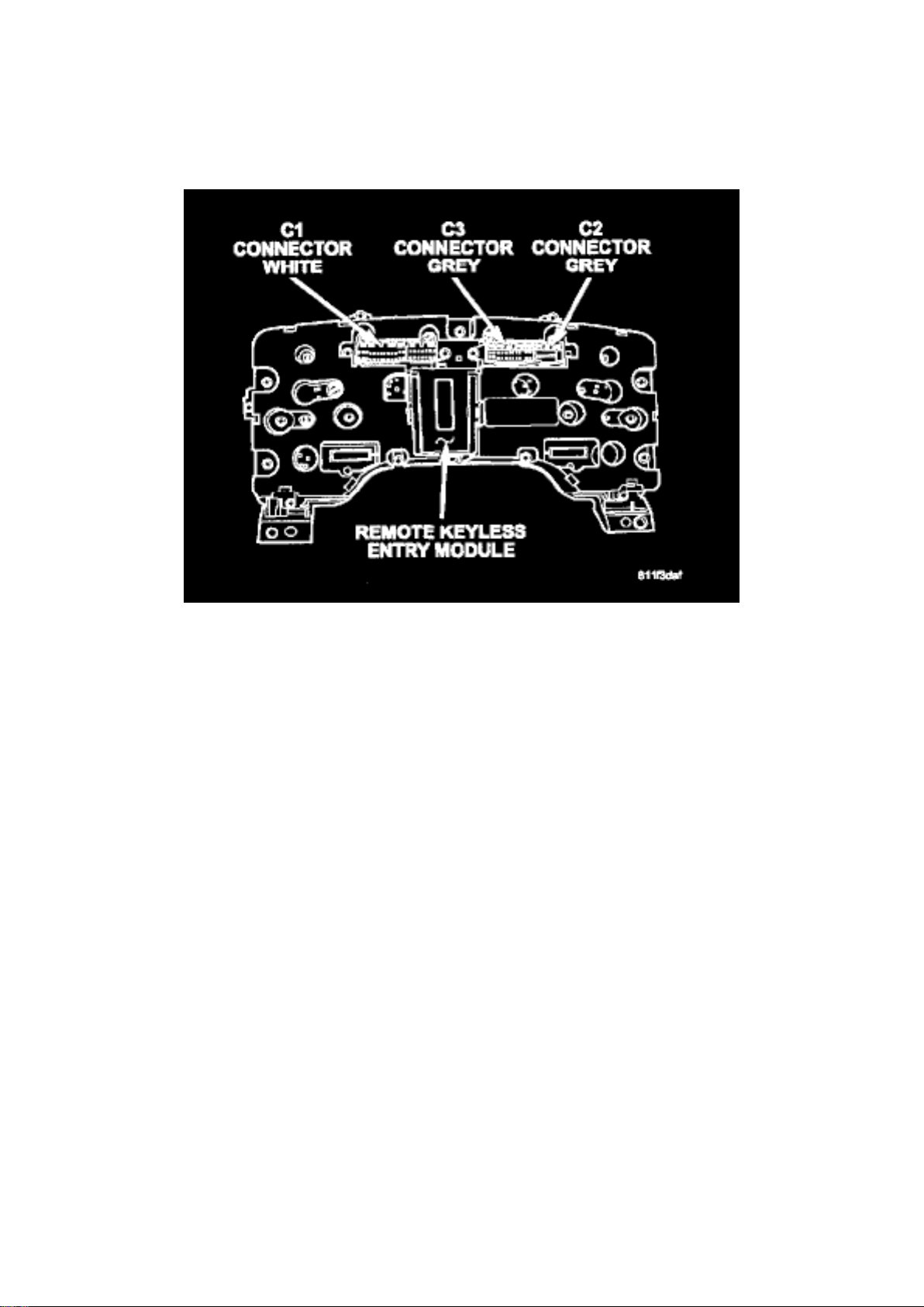
REMOVAL
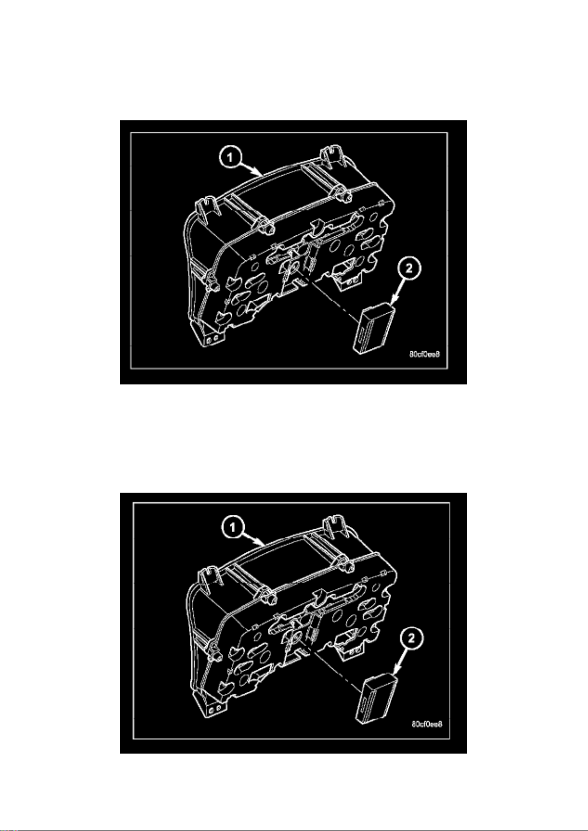
1. Disconnect and isolate the battery negative cable. 2. Remove the instrument cluster. 3. Remove
remote keyless entry module (2) from instrument cluster (1).
INSTALLATION
1. Install remote keyless entry module (2) to instrument cluster (1). 2. Install instrument cluster. 3.
Connect the battery negative cable.
Page 42
Dodge Ram Srt-10 Pickup Workshop Manual (V10-505 8.3L (2004))
Dodge Workshop Manuals > Relays and Modules > Relays and Modules - Body and Frame > Pedal Positioning Relay >
Component Information > Locations
Page 43

Module - Integrated Power (Front View)
Page 44
Dodge Ram Srt-10 Pickup Workshop Manual (V10-505 8.3L (2004))
Dodge Workshop Manuals > Relays and Modules > Relays and Modules - Body and Frame > Power Seat Control Module >
Component Information > Description and Operation
Power Seat Control Module: Description and Operation
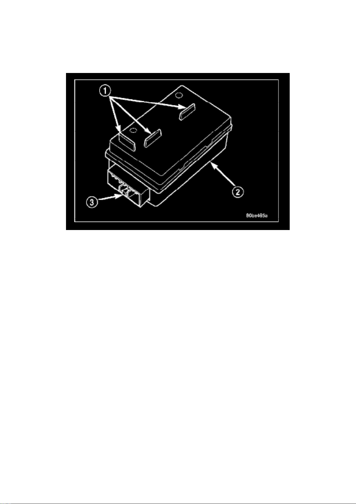
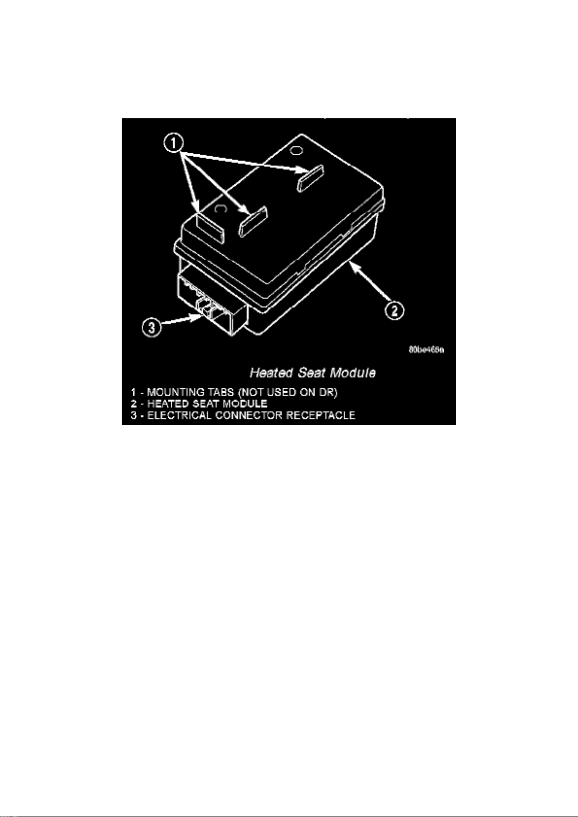
The heated seat module (2) is also known as the Seat Heat Interface Module. The heated seat
module is located under the drivers front seat cushion, where it is secured to a mounting bracket.
The heated seat module has a single connector receptacle (3) that allows the module to be
connected to all of the required inputs and outputs through the seat wire harness.
The heated seat module is an electronic microprocessor controlled device designed and
programmed to use inputs from the battery, the two heated seat switches and the two heated seat
sensors to operate and control the heated seat elements in both front seats and the two heated
seat indicator lamp Light-Emitting Diodes (LEDs) in each heated seat switch. The heated seat
module is also programmed to perform self-diagnosis of certain heated seat system functions and
provide feedback of that diagnosis through the heated seat switch indicator lamps.
The heated seat module cannot be repaired. If the heated seat module is damaged or faulty, the
entire module must be replaced.
The heated seat module operates on fused battery current received from the integrated power
module. Inputs to the module include a resistor multiplexed heated seat switch request circuit for
each of the two heated seat switches and the heated seat sensor inputs from the seat cushions of
each front seat. In response to those inputs the heated seat module controls battery current feeds
to the heated seat elements and sensors, and controls the ground for the heated seat switch
indicator lamps.
When a heated seat switch (Driver or Passenger) is depressed a signal is received by the heated
seat module, the module energizes the proper indicator LED (Low or High) in the switch by
grounding the indicator lamp circuit to indicate that the heated seat system is operating. At the
same time, the heated seat module energizes the selected heated seat sensor circuit and the
sensor provides the module with an input indicating the surface temperature of the selected seat
cushion.
Page 45

The Low heat set point is about 36° C (96.8° F), and the High heat set point is about 42°C (107.6°
F). If the seat cushion surface temperature input is below the temperature set point for the selected
temperature setting, the heated seat module energizes an N-channel Field Effect Transistor
(N-FET) within the module which energizes the heated seat elements in the selected seat cushion
and back. When the sensor input to the module indicates the correct temperature set point has
been achieved, the module de-energizes the N-FET which de-energizes the heated seat elements.
The heated seat module will continue to cycle the N-FET as needed to maintain the selected
temperature set point.
If the heated seat module detects a heated seat sensor value input that is out of range or a shorted
or open heated seat element circuit, it will notify the vehicle operator or the repair technician of this
condition by flashing the High and/or Low indicator lamps in the affected heated seat switch.
Page 46

Dodge Ram Srt-10 Pickup Workshop Manual (V10-505 8.3L (2004))
Dodge Workshop Manuals > Relays and Modules > Relays and Modules - Body and Frame > Power Seat Control Module >
Component Information > Description and Operation > Page 43
Page 47

Power Seat Control Module: Testing and Inspection
If a heated seat fails to heat and one or both of the indicator lamps on a heated seat switch flash. If
a heated seat heats but one or both indicator lamps on the heated seat switch fail to operate, test
the heated seat switch. If the heated seat switch checks OK, proceed as follows.
1. Check the heated seat element. 2. Check the heated seat sensor. 3. Check the heated seat
switch.
NOTE: Refer to Wiring for the location of complete heated seat system wiring diagrams and
connector pin-out information.
4. Using a voltmeter, backprobe the heated seat module connector, do not disconnect. Check for
voltage at the appropriate pin cavities. 12v should
be present. If OK go to Step 5, if Not, Repair the open or shorted voltage supply circuit as required.
5. Using a ohmmeter, backprobe the appropriate heated seat module connector, do not disconnect.
Check for proper continuity to ground on the
ground pin cavities. Continuity should be present. If OK replace the heated seat module with a
known good unit and retest system, if Not OK, Repair the open or shorted ground circuit as
required.
Page 48

Dodge Ram Srt-10 Pickup Workshop Manual (V10-505 8.3L (2004))
Dodge Workshop Manuals > Relays and Modules > Relays and Modules - Body and Frame > Power Seat Control Module >
Component Information > Description and Operation > Page 44
Page 49

Power Seat Control Module: Service and Repair
REMOVAL
1. Position the driver seat to the full rearward and inclined position. 2. Working under the driver
front seat, remove the two heated seat module retaining screws. Due to the fact that the retaining
screws are installed
with the seat cushion pan removed, a small right angle screwdriver will be required to access and
remove the screws.
3. Disconnect the seat wire harness connector from the connector receptacle on the back of the
heated seat module. Depress the connector retaining
tab and pull straight apart.
4. Remove the heated seat module from under the front seat.
INSTALLATION
1. Position the heated seat module under the front seat. 2. Connect the seat wire harness
connector on the connector receptacle on the back of the heated seat module. 3. Working under
the driver front seat, install the heated seat module retaining screws. 4. Re-position the driver seat.
Page 50
Dodge Ram Srt-10 Pickup Workshop Manual (V10-505 8.3L (2004))
Dodge Workshop Manuals > Relays and Modules > Relays and Modules - Body and Frame > Seat Heater Control Module >
Component Information > Diagrams
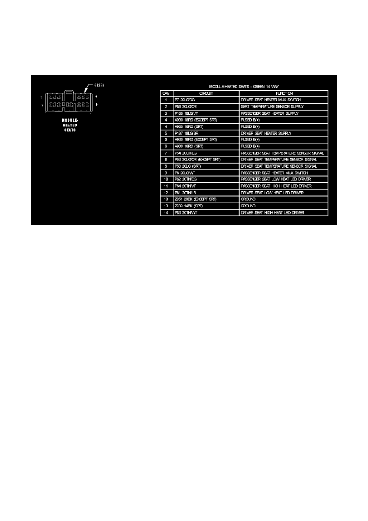
Module-Heated Seats
Page 51
Dodge Ram Srt-10 Pickup Workshop Manual (V10-505 8.3L (2004))
Dodge Workshop Manuals > Relays and Modules > Relays and Modules - Body and Frame > Seat Heater Control Module >
Component Information > Diagrams > Page 48
Seat Heater Control Module: Description and Operation
The heated seat module is also known as the Seat Heat Interface Module. The heated seat module
is located under the drivers front seat cushion, where it is secured to a mounting bracket. The
heated seat module has a single connector receptacle that allows the module to be connected to
all of the required inputs and outputs through the seat wire harness.
The heated seat module is an electronic microprocessor controlled device designed and
programmed to use inputs from the battery, the two heated seat switches and the two heated seat
sensors to operate and control the heated seat elements in both front seats and the two heated
seat indicator lamp Light-Emitting Diodes (LEDs) in each heated seat switch. The heated seat
module is also programmed to perform self-diagnosis of certain heated seat system functions and
provide feedback of that diagnosis through the heated seat switch indicator lamps.
The heated seat module cannot be repaired. If the heated seat module is damaged or faulty, the
entire module must be replaced.
The heated seat module operates on fused battery current received from the integrated power
module. Inputs to the module include a resistor multiplexed heated seat switch request circuit for
each of the two heated seat switches and the heated seat sensor inputs from the seat cushions of
each front seat. In response to those inputs the heated seat module controls battery current feeds
to the heated seat elements and sensors, and controls the ground for the heated seat switch
indicator lamps.
When a heated seat switch (Driver or Passenger) is depressed a signal is received by the heated
seat module, the module energizes the proper indicator LED (Low or High) in the switch by
Page 52

grounding the indicator lamp circuit to indicate that the heated seat system is operating. At the
same time, the heated seat module energizes the selected heated seat sensor circuit and the
sensor provides the module with an input indicating the surface temperature of the selected seat
cushion.
The Low heat set point is about 36° C (96.8° F), and the High heat set point is about 42° C (107.6°
F). If the seat cushion surface temperature input is below the temperature set point for the selected
temperature setting, the heated seat module energizes an Nm-channel Field Effect Transistor
(Nm-FEET) within the module which energizes the heated seat elements in the selected seat
cushion and back. When the sensor input to the module indicates the correct temperature set point
has been achieved, the module de-energizes the Nm-FEET which de-energizes the heated seat
elements. The heated seat module will continue to cycle the Nm-FEET as needed to maintain the
selected temperature set point.
If the heated seat module detects a heated seat sensor value input that is out of range or a shorted
or open heated seat element circuit, it will notify the vehicle operator or the repair technician of this
condition by flashing the High and/or Low indicator lamps in the affected heated seat switch. Refer
to Diagnosis and Testing Heated Seat System in Heated Systems for flashing LED diagnosis and
testing procedures. Refer to Diagnosis and Testing Heated Seat Module for heated seat module
diagnosis and testing procedures.
Page 53

Dodge Ram Srt-10 Pickup Workshop Manual (V10-505 8.3L (2004))
Dodge Workshop Manuals > Relays and Modules > Relays and Modules - Body and Frame > Seat Heater Control Module >
Component Information > Diagrams > Page 49
Page 54

Seat Heater Control Module: Testing and Inspection
If a heated seat fails to heat and one or both of the indicator lamps on a heated seat switch flash,
refer to Diagnosis and Testing Heated Seat System in Heated Seats for the location of flashing
LED heated seat system diagnosis and testing procedures. If a heated seat heats but one or both
indicator lamps on the heated seat switch fail to operate, test the heated seat switch. Refer to
Diagnosis and Testing Heated Seat Switch in Heated Seats for heated seat switch diagnosis and
testing procedures. If the heated seat switch checks OK, proceed as follows.
1. Check the heated seat element. 2. Check the heated seat sensor. 3. Check the heated seat
switch.
NOTE: Refer to Wiring for the location of complete heated seat system wiring diagrams and
connector pin-out information.
4. Using a voltmeter, backprobe the appropriate heated seat module connector, do not disconnect.
Check for voltage at the appropriate pin cavities.
12v should be present. If OK go to Step 5, if Not, Repair the open or shorted voltage supply circuit
as required.
5. Using a ohmmeter, backprobe the appropriate heated seat module connector, do not disconnect.
Check for proper continuity to ground on the
ground pin cavities. Continuity should be present. If OK replace the heated seat module with a
known good unit and retest system, if Not OK, Repair the open or shorted ground circuit as
required.
Page 55

Dodge Ram Srt-10 Pickup Workshop Manual (V10-505 8.3L (2004))
Dodge Workshop Manuals > Relays and Modules > Relays and Modules - Body and Frame > Seat Heater Control Module >
Component Information > Diagrams > Page 50
Page 56

Seat Heater Control Module: Service and Repair
REMOVAL
1. Position the driver seat to the full rearward and inclined position. 2. Working under the driver
front seat, remove the two heated seat module retaining screws. Due to the fact that the retaining
screws are installed
with the seat cushion pan removed, a small right angle screwdriver will be required to access and
remove the screws.
3. Disconnect the seat wire harness connector from the connector receptacle on the back of the
heated seat module. Depress the connector retaining
tab and pull straight apart.
4. Remove the heated seat module from under the front seat.
INSTALLATION
1. Position the heated seat module under the front seat. 2. Connect the seat wire harness
connector on the connector receptacle on the back of the heated seat module. 3. Working under
the driver front seat, install the heated seat module retaining screws. 4. Re-position the driver seat.
Page 57
Dodge Ram Srt-10 Pickup Workshop Manual (V10-505 8.3L (2004))
Dodge Workshop Manuals > Relays and Modules > Relays and Modules - Body and Frame > Trailer Towing Relay >
Component Information > Locations
Page 58

Module - Integrated Power (Front View)
Page 59
Dodge Ram Srt-10 Pickup Workshop Manual (V10-505 8.3L (2004))
Dodge Workshop Manuals > Relays and Modules > Relays and Modules - Brakes and Traction Control > Electronic Brake
Control Module > Component Information > Locations
Electronic Brake Control Module: Locations
EBC 125 (RWAL)
EBC 325 (ABS)
Page 60
Dodge Ram Srt-10 Pickup Workshop Manual (V10-505 8.3L (2004))
Dodge Workshop Manuals > Relays and Modules > Relays and Modules - Brakes and Traction Control > Electronic Brake
Control Module > Component Information > Locations > Page 58
Electronic Brake Control Module: Diagrams
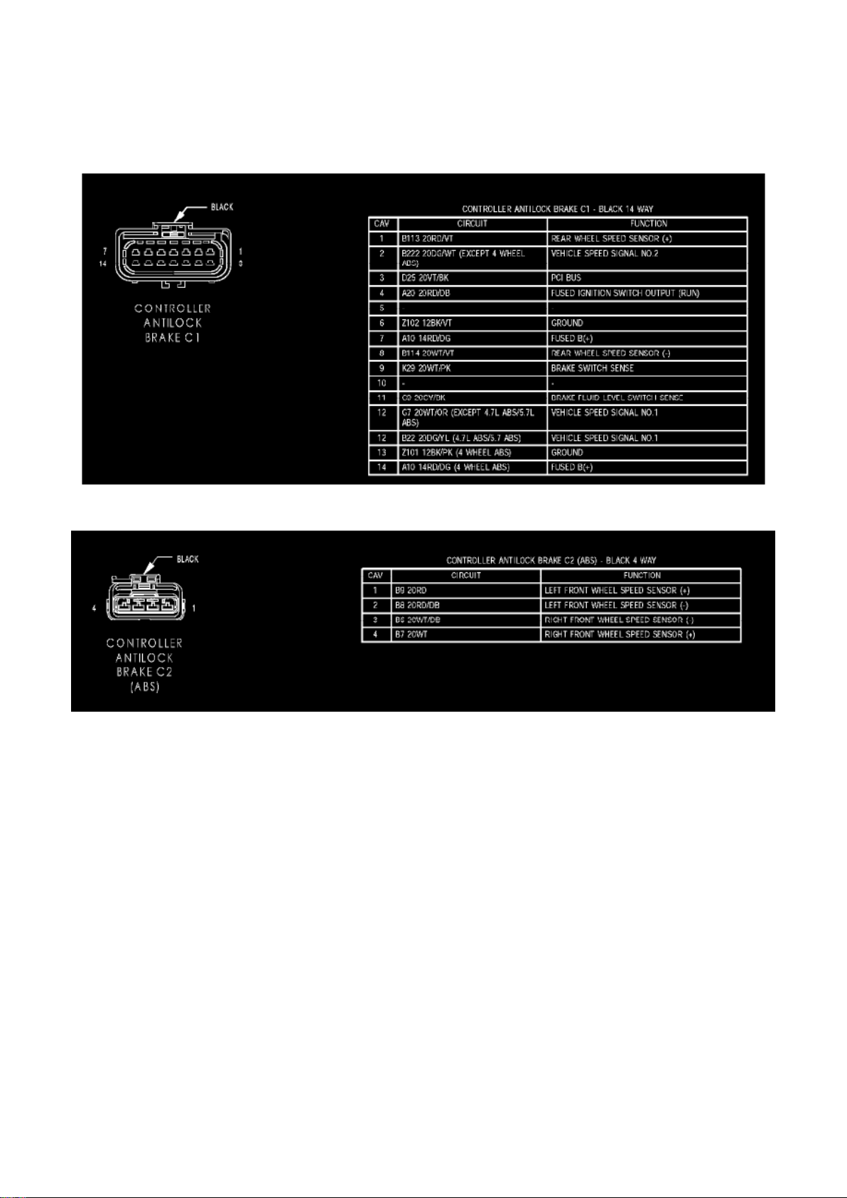
Controller Antilock Brake C1
Controller Antilock Brake C2 (ABS)
Page 61
Dodge Ram Srt-10 Pickup Workshop Manual (V10-505 8.3L (2004))
Dodge Workshop Manuals > Relays and Modules > Relays and Modules - Brakes and Traction Control > Electronic Brake
Control Module > Component Information > Locations > Page 59
Electronic Brake Control Module: Description and Operation
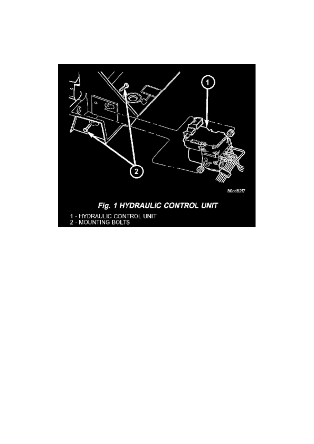
Fig.1 Hydraulic Control Unit
CONTROLLER ANTILOCK BRAKE (CAB)
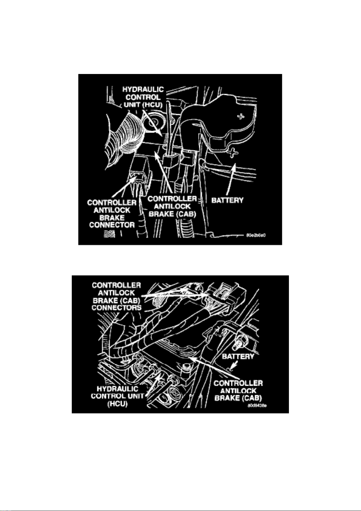
The Controller Antilock Brake (CAB) is mounted to the Hydraulic Control Unit (HCU) and operates
the ABS system.
The CAB voltage source is through the ignition switch in the RUN position. The CAB contains a self
check program that illuminates the ABS warning light when a system fault is detected. Faults are
stored in a diagnostic program memory and are accessible with the DRB III scan tool. ABS faults
remain in memory until cleared, or until after the vehicle is started approximately 50 times. Stored
faults are not erased if the battery is disconnected.
NOTE: If the CAB is being replaced with a new CAB is must be reprogrammed with the use of a
DRB III.
TRW EBC 125 CONTROLLER ANTILOCK BRAKE
The CAB includes a microprocessor and two solenoids that control the valves that control brake
pressure during RWAL braking and circuits that: Monitor the brake switch input to tell whether or not to prepare for possible antilock braking
- Monitor the brake fluid level switch input to tell whether or not the state of the hydraulics has a
problem
Page 62

- Monitor the wheel speed sensor input to determine when a rear wheel is tending to lock up
- Operate the integral hydraulic control unit (HCU) during antilock braking based on comparing the
speed sensor to information programmed in memory
- Detect RWAL system related problems and take diagnostic action
- Able to execute self-tests and output control commands
TRW EBC 325 CONTROLLER ANTILOCK BRAKE
The CAB includes a microprocessor and six solenoids that control brake pressure during antilock
braking. The CAB also has circuits that monitor the following: Brake switch input is monitored to determine whether or not to prepare for possible ABS braking
- Monitor the brake fluid level switch input to tell whether or not the state of the hydraulics has a
problem
- Wheel speed sensors are monitored to determine when a wheel is tending to lock up. The CAB
will operate the valves in the HCU to control braking pressure during ABS braking
- Detect ABS system related problems and take diagnostic action
- Able to execute self-tests and output control commands
Page 63

Dodge Ram Srt-10 Pickup Workshop Manual (V10-505 8.3L (2004))
Dodge Workshop Manuals > Relays and Modules > Relays and Modules - Brakes and Traction Control > Electronic Brake
Control Module > Component Information > Locations > Page 60
Page 64

Electronic Brake Control Module: Service and Repair
REMOVAL
1. Remove the negative battery cable from the battery. 2. Pull up on the CAB harness connector
release and remove connector. 3. Remove the CAB mounting bolts. 4. Remove the pump
connector from the CAB. 5. Remove the CAB from the HCU.
INSTALLATION
NOTE: If the CAB is being replaced with a new CAB is must be reprogrammed with the use of a
DRB III.
1. Install CAB to the HCU. 2. Install the pump connector to the CAB. 3. Install mounting bolts.
Tighten to 2 Nm (16 in. lbs.). 4. Install the wiring harness connector to the CAB and push down on
the release to secure the connector. 5. Install negative battery cable to the battery.
Page 65
Dodge Ram Srt-10 Pickup Workshop Manual (V10-505 8.3L (2004))
Dodge Workshop Manuals > Relays and Modules > Relays and Modules - HVAC > Blower Motor Relay > Component
Information > Locations
Page 66

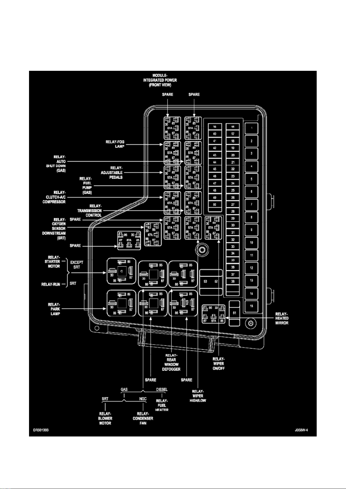
Module - Integrated Power (Front View)
Page 67
Dodge Ram Srt-10 Pickup Workshop Manual (V10-505 8.3L (2004))
Dodge Workshop Manuals > Relays and Modules > Relays and Modules - HVAC > Compressor Clutch Relay > Component
Information > Locations
Page 68

Module - Integrated Power (Front View)
Page 69
Dodge Ram Srt-10 Pickup Workshop Manual (V10-505 8.3L (2004))
Dodge Workshop Manuals > Relays and Modules > Relays and Modules - HVAC > Compressor Clutch Relay > Component
Information > Locations > Page 68
Compressor Clutch Relay: Description and Operation
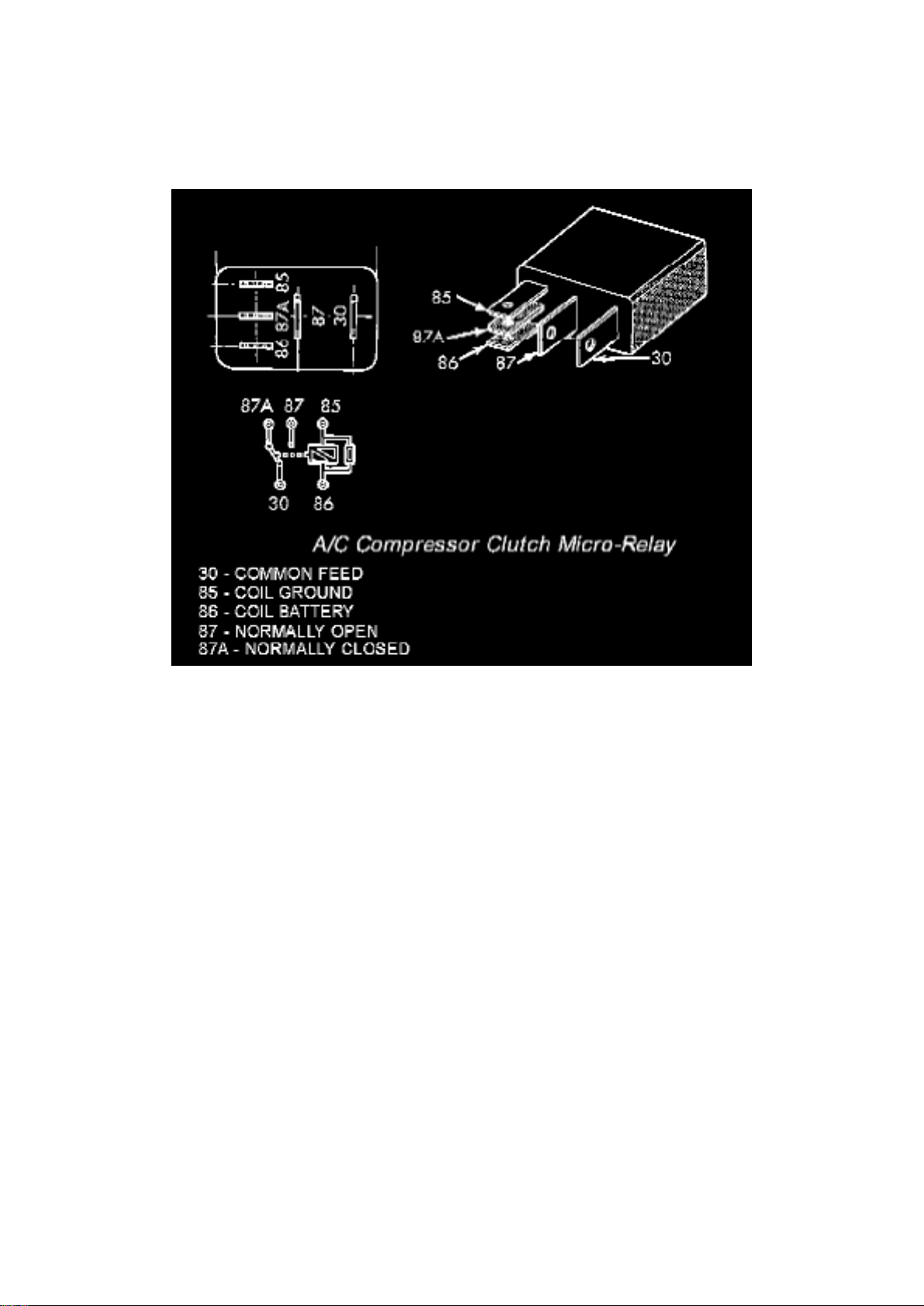
A/C Compressor Clutch Micro-Relay
The A/C compressor clutch relay is a International Standards Organization (ISO) micro-relay.
Relays conforming to the ISO specifications have common physical dimensions, current capacities,
terminal patterns, and terminal functions. The ISO micro-relay terminal functions are the same as a
conventional ISO relay. However, the ISO micro-relay terminal pattern (or footprint) is different, the
current capacity is lower, and the physical dimensions are smaller than those of the conventional
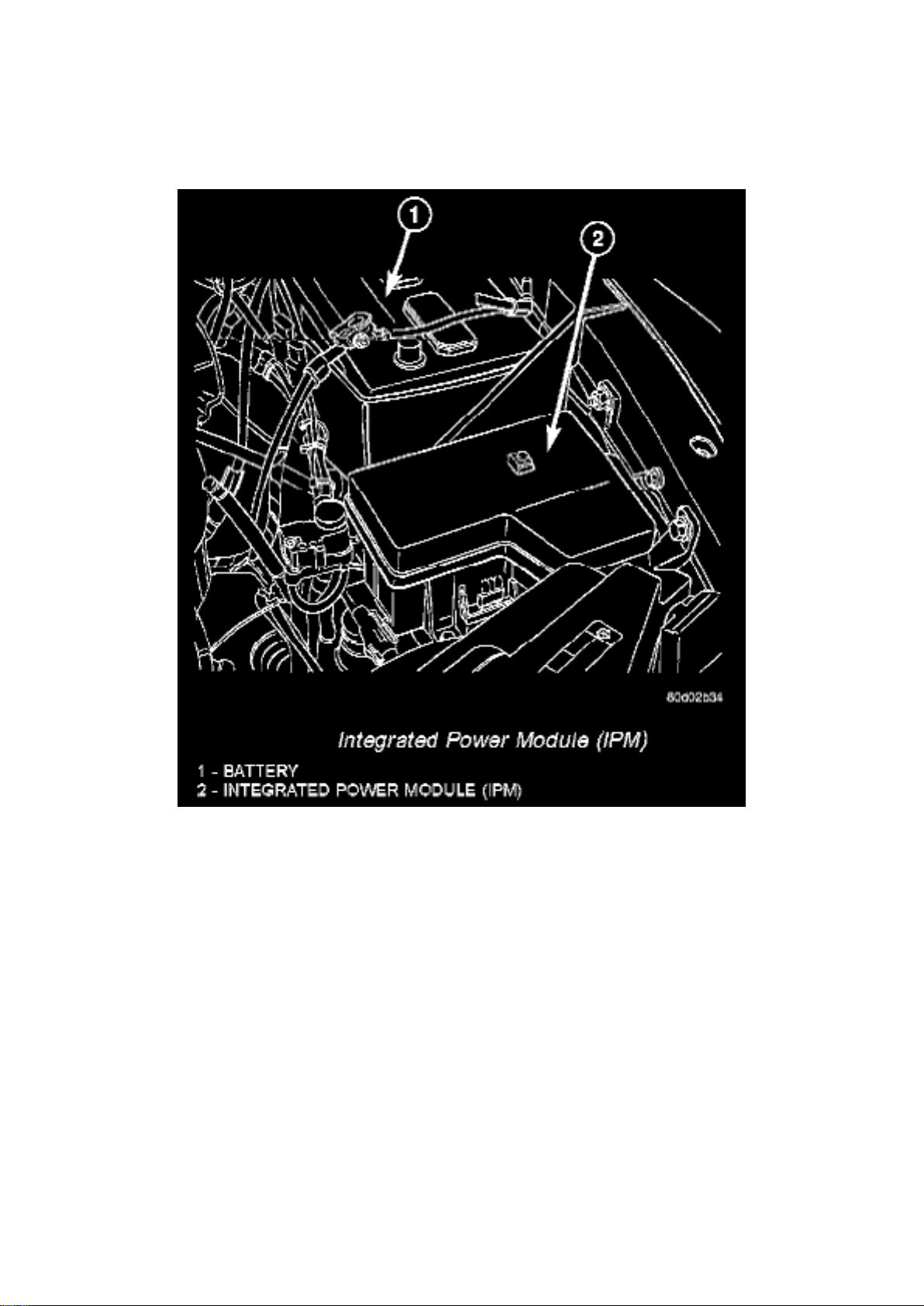
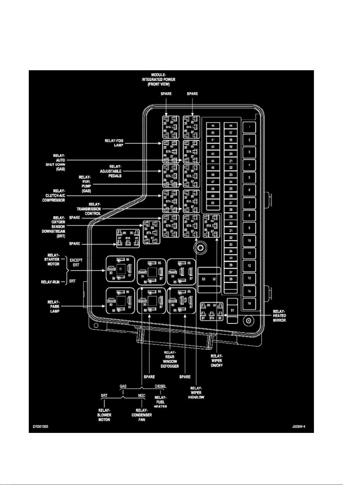
ISO relay. The A/C compressor clutch relay is located in the integrated power module (IPM) in the
engine compartment. See the fuse and relay layout label affixed to the inside surface of the IPM
cover for A/C compressor clutch relay identification and location.
The black, molded plastic case is the most visible component of the A/C compressor clutch relay.
Five male spade-type terminals extend from the bottom of the base to connect the relay to the
vehicle electrical system, and the ISO designation for each terminal is molded into the base
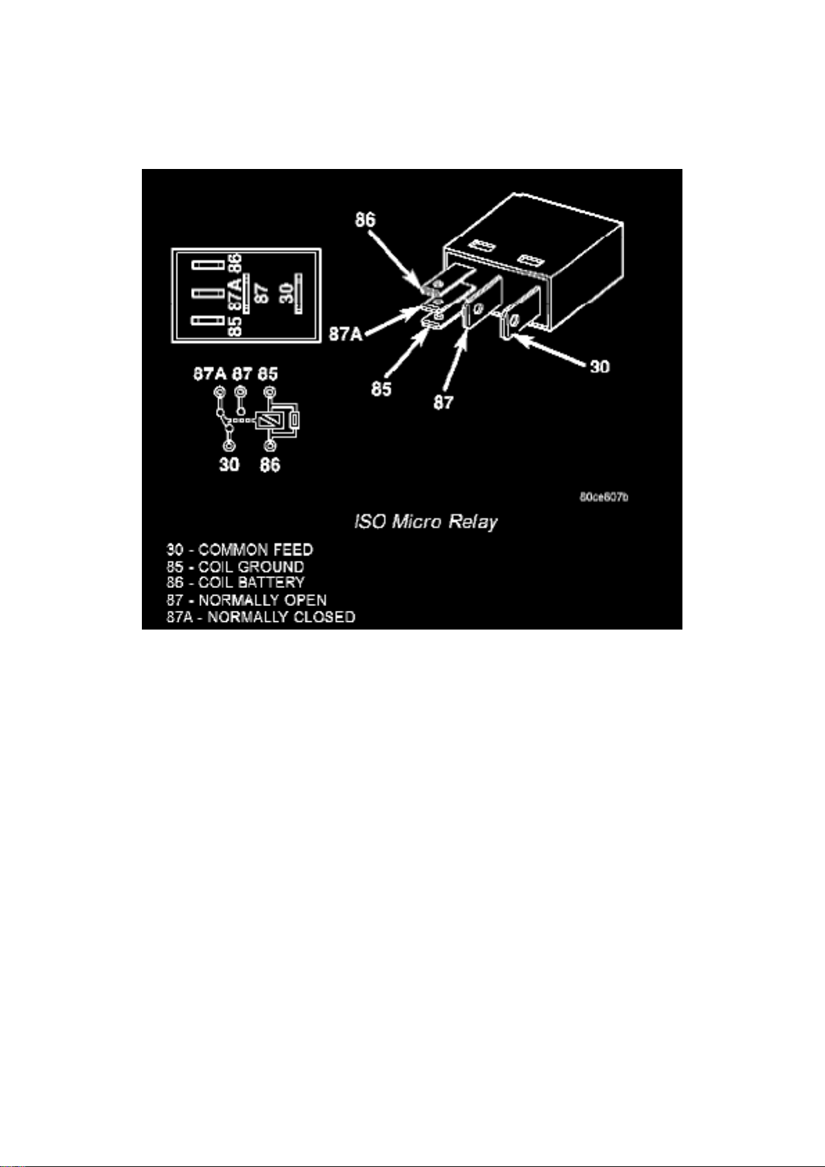
adjacent to each terminal. The ISO terminal designations are as follows:
- 30 (Common Feed) - This terminal is connected to the movable contact point of the relay.
- 85 (Coil Ground) - This terminal is connected to the ground feed side of the relay control coil.
- 86 (Coil Battery) - This terminal is connected to the battery feed side of the relay control coil.
- 87 (Normally Open) - This terminal is connected to the normally open fixed contact point of the
relay.
Page 70

- 87A (Normally Closed) - This terminal is connected to the normally closed fixed contact point of
the relay.
The A/C compressor clutch relay is an electromechanical switch that uses a low current input from
the powertrain control module (PCM) or engine control module (ECM) depending on engine
application, to control the high current output to the compressor clutch electromagnetic coil. The
movable common feed contact point is held against the fixed normally closed contact point by
spring pressure. When the relay coil is energized, an electromagnetic field is produced by the coil
windings. This electromagnetic field draws the movable relay contact point away from the fixed
normally closed contact point, and holds it against the fixed normally open contact point. When the
relay coil is de-energized, spring pressure returns the movable contact point back against the fixed
normally closed contact point. The resistor or diode is connected in parallel with the relay coil in the
relay, and helps to dissipate voltage spikes and electromagnetic interference that can be generated
as the electromagnetic field of the relay coil collapses.
The A/C compressor clutch relay terminals are connected to the vehicle electrical system through a
receptacle in the integrated power module (IPM). The inputs and outputs of the A/C compressor
clutch relay include:
- The common feed terminal (30) receives a battery current input from a fuse in the IPM through a
fused B(+) circuit at all times.
- The coil ground terminal (86) receives a ground input from the PCM/ECM through the A/C
compressor clutch relay control circuit only when the PCM/ ECM electronically pulls the control
circuit to ground.
- The coil battery terminal (85) receives a battery current input from PTC 1 in the IPM through a
fused ignition switch output (run) circuit only when the ignition switch is in the On position.
- The normally open terminal (87) provides a battery current output to the compressor clutch coil
through the A/C compressor clutch relay output circuit only when the A/C compressor clutch relay
coil is energized.
- The normally closed terminal (87A) is not connected to any circuit in this application, but provides
a battery current output only when the A/C compressor clutch relay coil is de-energized.
Refer to the appropriate wiring information for diagnosis and testing of the micro-relay and for
complete HVAC wiring diagrams.
Page 71
Dodge Ram Srt-10 Pickup Workshop Manual (V10-505 8.3L (2004))
Dodge Workshop Manuals > Relays and Modules > Relays and Modules - HVAC > Compressor Clutch Relay > Component
Information > Locations > Page 69
Compressor Clutch Relay: Service and Repair
REMOVAL
1. Disconnect and isolate the negative battery cable.
Integrated Power Module (IPM)
2. Remove the cover from the integrated power module (IPM). 3. Refer to the fuse and relay layout
label on the IPM cover for compressor clutch relay identification and location. 4. Remove the A/C
compressor clutch relay from the IPM.
INSTALLATION
1. See the fuse and relay layout label affixed to the underside of the IPM cover for A/C compressor
clutch relay location. 2. Position the A/C compressor clutch relay in the proper receptacle in the
IPM. 3. Align the A/C compressor clutch relay terminals with the terminal cavities in the IPM
receptacle. 4. Push down firmly on the A/C compressor clutch relay until the terminals are fully
seated in the terminal cavities in the IPM receptacle. 5. Install the cover onto the IPM. 6. Reconnect
Page 72

the negative battery cable.
Page 73
Dodge Ram Srt-10 Pickup Workshop Manual (V10-505 8.3L (2004))
Dodge Workshop Manuals > Relays and Modules > Relays and Modules - HVAC > Condenser Fan Motor Relay, HVAC >
Component Information > Locations
Page 74

Module - Integrated Power (Front View)
Page 75

Dodge Ram Srt-10 Pickup Workshop Manual (V10-505 8.3L (2004))
Dodge Workshop Manuals > Relays and Modules > Relays and Modules - Lighting and Horns > Brake Lamp Relay >
Component Information > Description and Operation
Page 76

Brake Lamp Relay: Description and Operation
DESCRIPTION
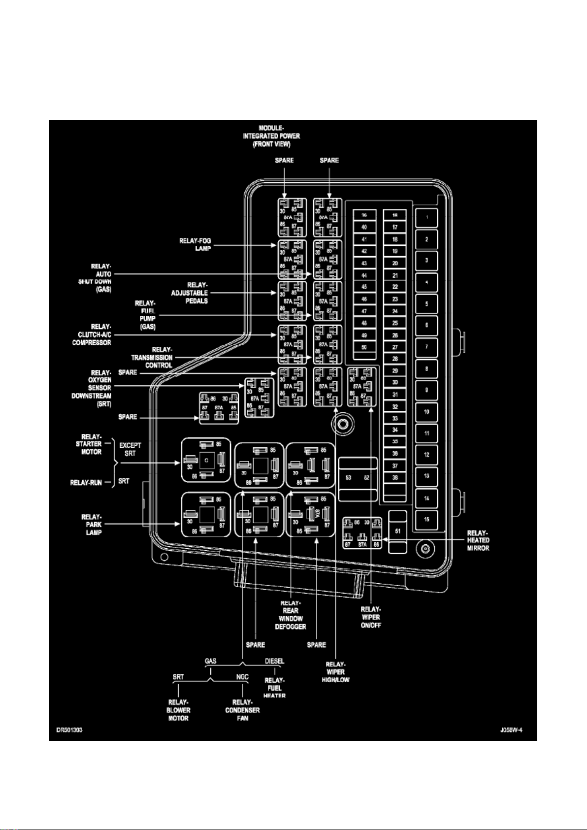
The exterior lighting system for this model include the following components:
^ Backup Lamps ^ Brake Lamps ^ Daytime Running Lamps ^ Front Fog Lamps ^ Hazard Warning
Lamps ^ Headlamps ^ Park Lamps ^ Turn Signal Lamps
Other components of the exterior lighting system for this model include:
^ Backup Lamp Switch ^ Brake Lamp Switch ^ Front Control Module ^ Front Fog Lamp Relay See:
Relays and Modules - Power and Ground Distribution/Relay Box ^ Hazard Switch ^ Multi-Function
Switch ^ Park Lamp Relay See: Relays and Modules - Power and Ground Distribution/Relay Box ^
Trailer Tow Connectors
Some of the interior and exterior lighting functions are governed by the front control module. The
headlamp, dome, and door ajar switches provide signals to the instrument cluster. The instrument
cluster sends a J1850 message to the front control module to enable the necessary components
for illumination. Hard wired circuitry connects the exterior lighting system components to the
electrical system of the vehicle. Refer to the appropriate wiring information
Page 77
Dodge Ram Srt-10 Pickup Workshop Manual (V10-505 8.3L (2004))
Dodge Workshop Manuals > Relays and Modules > Relays and Modules - Lighting and Horns > Fog/Driving Lamp Relay >
Component Information > Locations
Page 78

Module - Integrated Power (Front View)
Page 79
Dodge Ram Srt-10 Pickup Workshop Manual (V10-505 8.3L (2004))
Dodge Workshop Manuals > Relays and Modules > Relays and Modules - Lighting and Horns > Fog/Driving Lamp Relay >
Component Information > Locations > Page 80
Fog/Driving Lamp Relay: Description and Operation
The front fog lamp relay is located in the Power Distribution Center (PDC)See: Relays and Modules
- Power and Ground Distribution/Relay Box Applications and ID in the engine compartment of the
vehicle. The front fog lamp relay is a conventional International Standards Organization (ISO) micro
relay. Relays conforming to the ISO specifications have common physical dimensions, current
capacities, terminal patterns, and terminal functions. The relay is contained within a small,
rectangular, molded plastic housing and is connected to all of the required inputs and outputs by
five integral male spade-type terminals that extend from the bottom of the relay base.
The front fog lamp relay cannot be adjusted or repaired and, if faulty or damaged, the unit must be
replaced.
The front fog lamp relay is an electromechanical switch that uses a low current input from the Front
Control Module (FCM) to control a high current output to the front fog lamps. The movable common
feed contact point is held against the fixed normally closed contact point by spring pressure. When
the relay coil is energized, an electromagnetic field is produced by the coil windings. This
electromagnetic field draws the movable relay contact point away from the fixed normally closed
contact point, and holds it against the fixed normally open contact point. When the relay coil is
de-energized, spring pressure returns the movable contact point back against the fixed normally
closed contact point. A resistor is connected in parallel with the relay coil in the relay, and helps to
dissipate voltage spikes and electromagnetic interference that can be generated as the
electromagnetic field of the relay coil collapses.
Page 80

The front fog lamp relay terminals are connected to the vehicle electrical system through a
connector receptacle in the Power Distribution Center (PDC). The inputs and outputs of the front
fog lamp relay include:
- Common Feed Terminal - The common feed terminal (30) receives battery voltage at all times
from a fuse in the PDC through a fused B(+) circuit.
- Coil Ground Terminal - The coil ground terminal (85) is connected to a control output of the Front
Control Module (FCM) through a front fog lamp relay control circuit. The FCM controls front fog
lamp operation by controlling a ground path through this circuit.
- Coil Battery Terminal - The coil battery terminal (86) receives battery voltage at all times from a
fuse in the PDC through a fused B(+) circuit.
- Normally Open Terminal - The normally open terminal (87) is connected to the front fog lamps
through a front fog lamp relay output circuit and provides battery voltage to the front fog lamps
whenever the relay is energized.
- Normally Closed Terminal - The normally closed terminal (87A) is not connected in this
application.
The front fog lamp relay can be diagnosed using conventional diagnostic tools and methods. Refer
to the appropriate wiring information for diagnosis and testing of the front fog lamp micro-relay and
for complete wiring diagrams.
Page 81

Dodge Ram Srt-10 Pickup Workshop Manual (V10-505 8.3L (2004))
Dodge Workshop Manuals > Relays and Modules > Relays and Modules - Lighting and Horns > Fog/Driving Lamp Relay >
Component Information > Locations > Page 81
Page 82

Fog/Driving Lamp Relay: Service and Repair
WARNING: ON VEHICLES EQUIPPED WITH AIR-BAGS, DISABLE THE SUPPLEMENTAL
RESTRAINT SYSTEM BEFORE ATTEMPTING ANY STEERING WHEEL, STEERING COLUMN,
DRIVER AIRBAG, PASSENGER AIRBAG, SEAT BELT TENSIONER, FRONT IMPACT
SENSORS, SIDE CURTAIN AIRBAG, OR INSTRUMENT PANEL COMPONENT DIAGNOSIS OR
SERVICE. DISCONNECT AND ISOLATE THE BATTERY NEGATIVE (GROUND) CABLE, THEN
WAIT TWO MINUTES FOR THE SYSTEM CAPACITOR TO DISCHARGE BEFORE
PERFORMING FURTHER DIAGNOSIS OR SERVICE. THIS IS THE ONLY SURE WAY TO
DISABLE THE SUPPLEMENTAL RESTRAINT SYSTEM. FAILURE TO TAKE THE PROPER
PRECAUTIONS COULD RESULT IN ACCIDENTAL AIRBAG DEPLOYMENT AND POSSIBLE
PERSONAL INJURY.
REMOVAL
1. Disconnect and isolate the battery negative cable. 2. Remove the cover for the Power
Distribution Center (PDC). 3. Remove the front fog lamp relay by grasping it firmly and pulling it
straight out from the receptacle in the PDC.
INSTALLATION
1. Position the front fog lamp relay to the proper receptacle in the Power Distribution Center (PDC).
2. Align the front fog lamp relay terminals with the terminal cavities in the PDC. 3. Press firmly and
evenly on the top of the front fog lamp relay until the terminals are fully seated in the PDC. 4.
Reconnect the battery negative cable.
Page 83
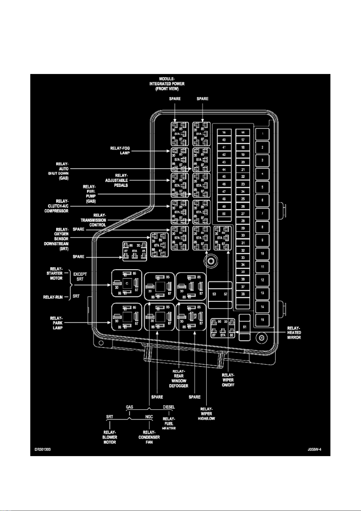
Dodge Ram Srt-10 Pickup Workshop Manual (V10-505 8.3L (2004))
Dodge Workshop Manuals > Relays and Modules > Relays and Modules - Lighting and Horns > Parking Lamp Relay >
Component Information > Locations
Page 84

Module - Integrated Power (Front View)
Page 85
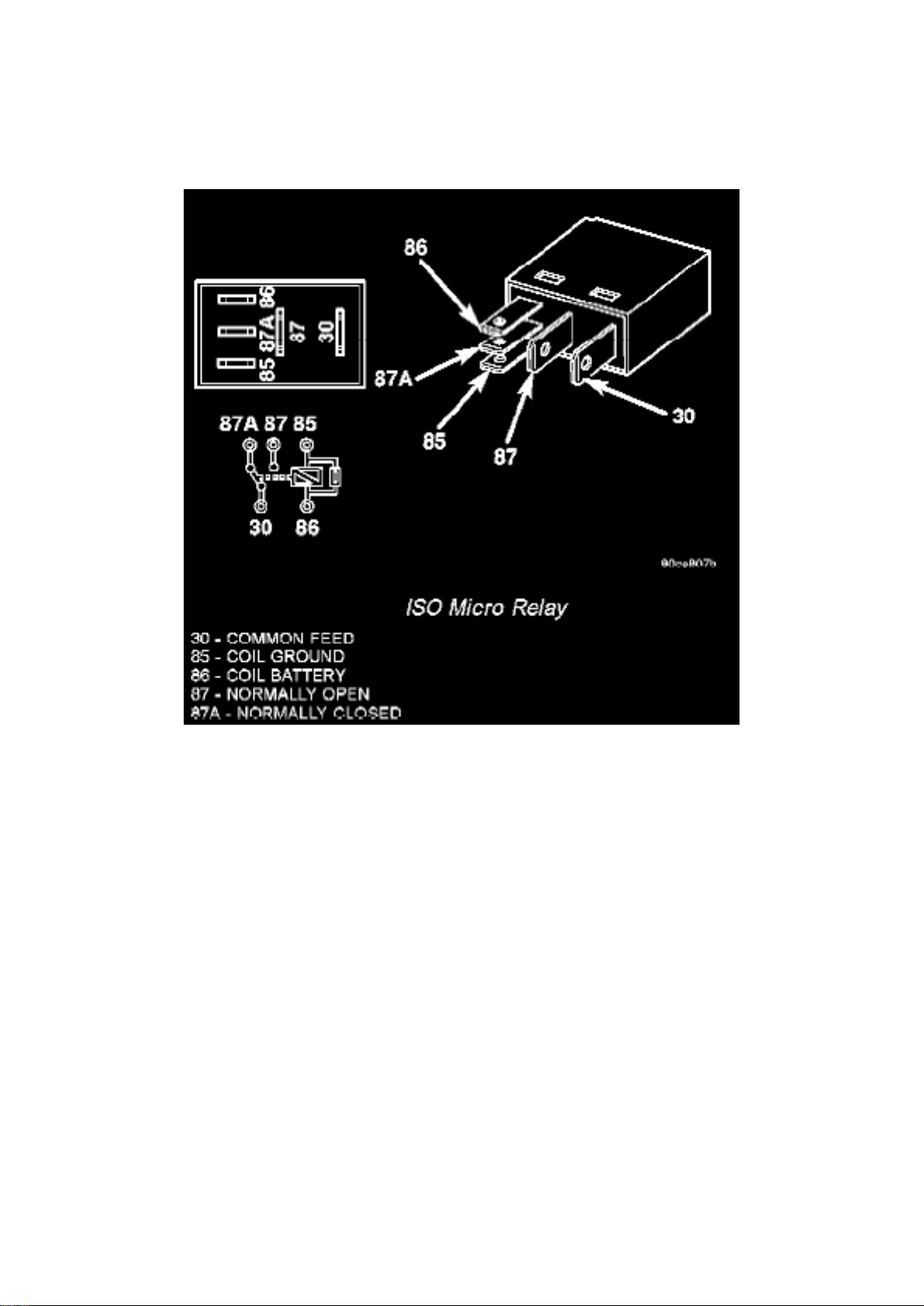
Dodge Ram Srt-10 Pickup Workshop Manual (V10-505 8.3L (2004))
Dodge Workshop Manuals > Relays and Modules > Relays and Modules - Lighting and Horns > Parking Lamp Relay >
Component Information > Locations > Page 85
Parking Lamp Relay: Description and Operation
The park lamp relay is located in the Power Distribution Center (PDC) of the vehicle. The park lamp
relay is a conventional International Standards Organization (ISO) micro relay. Relays conforming
to the ISO specifications have common physical dimensions, current capacities, terminal patterns,
and terminal functions.
The park lamp relay cannot be adjusted or repaired and, if faulty or damaged, the unit must be
replaced.
The park lamp relay is an electromechanical switch that uses a low current input from the Front
Control Module (FCM) to control a high current output to the park lamps. The movable common
feed contact point is held against the fixed normally closed contact point by spring pressure. When
the relay coil is energized, an electromagnetic field is produced by the coil windings. This
electromagnetic field draws the movable relay contact point away from the fixed normally closed
contact point, and holds it against the fixed normally open contact point. When the relay coil is
de-energized, spring pressure returns the movable contact point back against the fixed normally
closed contact point. A resistor is connected in parallel with the relay coil in the relay, and helps to
dissipate voltage spikes and electromagnetic interference that can be generated as the
electromagnetic field of the relay coil collapses.
The park lamp relay terminals are connected to the vehicle electrical system through a connector in
the Junction Block (JB). The inputs and outputs of the headlamp low beam relay include:
Page 86

- Common Feed Terminal - The common feed terminal (30) is connected to the park lamps through
the park lamp relay output circuit and provides ground to the park lamps when the relay is
de-energized, and battery current to the park lamps whenever the relay is energized.
- Coil Ground Terminal - The coil ground terminal (85) is connected to a control output of the Front
Control Module (FCM) through a park lamp relay control circuit. The FCM controls park lamp
operation by controlling a ground path through this circuit.
- Coil Battery Terminal - The coil battery terminal (86) receives battery current at all times from a
fuse in the PDC through a fused B(+) circuit.
- Normally Open Terminal - The normally open terminal (87) receives battery current at all times
from a fuse in the Power Distribution Center (PDC) through a fused B(+) circuit.
- Normally Closed Terminal - The normally closed terminal (87A) is connected to ground at all
times.
The park lamp relay can be diagnosed using conventional diagnostic tools and methods.
Page 87
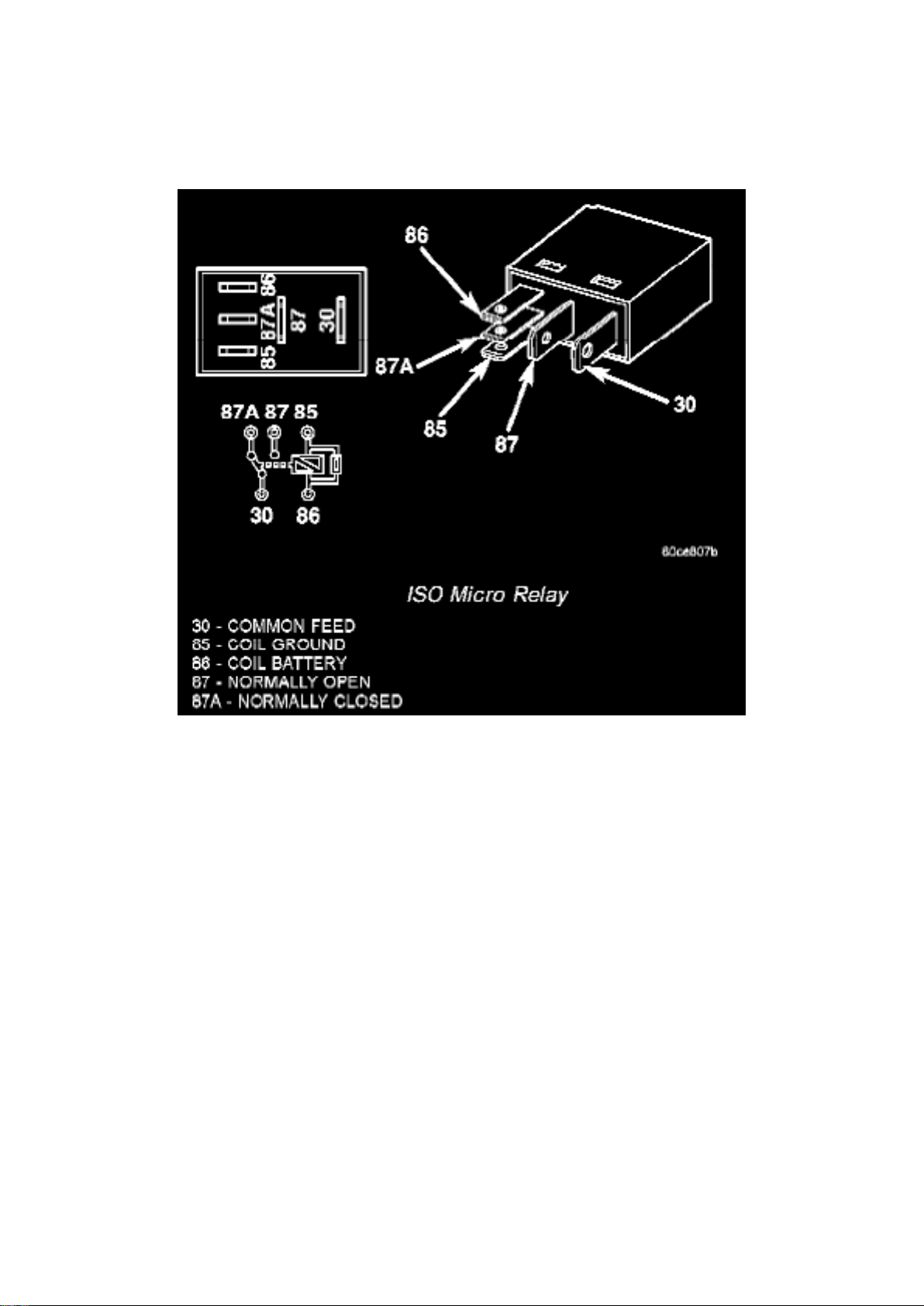
Dodge Ram Srt-10 Pickup Workshop Manual (V10-505 8.3L (2004))
Dodge Workshop Manuals > Relays and Modules > Relays and Modules - Lighting and Horns > Parking Lamp Relay >
Component Information > Locations > Page 86
Parking Lamp Relay: Testing and Inspection
The park lamp relay is located in the Power Distribution Center (PDC). Refer to the appropriate
wiring information.
WARNING: ON VEHICLES EQUIPPED WITH AIR-BAGS, DISABLE THE SUPPLEMENTAL
RESTRAINT SYSTEM BEFORE ATTEMPTING ANY STEERING WHEEL, STEERING COLUMN,
DRIVER AIRBAG, PASSENGER AIRBAG, SEAT BELT TENSIONER, FRONT IMPACT
SENSORS, SIDE CURTAIN AIRBAG, OR INSTRUMENT PANEL COMPONENT DIAGNOSIS OR
SERVICE. DISCONNECT AND ISOLATE THE BATTERY NEGATIVE (GROUND) CABLE, THEN
WAIT TWO MINUTES FOR THE SYSTEM CAPACITOR TO DISCHARGE BEFORE
PERFORMING FURTHER DIAGNOSIS OR SERVICE. THIS IS THE ONLY SURE WAY TO
DISABLE THE SUPPLEMENTAL RESTRAINT SYSTEM. FAILURE TO TAKE THE PROPER
PRECAUTIONS COULD RESULT IN ACCIDENTAL AIRBAG DEPLOYMENT AND POSSIBLE
PERSONAL INJURY.
1. Remove the park lamp relay from the PDC. 2. A relay in the de-energized position should have
continuity between terminals 87A and 30, and no continuity between terminals 87 and 30. If OK,
go to Step 3. If not OK, replace the faulty relay.
3. Resistance between terminals 85 and 86 (electromagnet) should be 75 ± 8 ohms. If OK, go to
Step 4. If not OK, replace the faulty relay. 4. Connect a battery to terminals 85 and 86. There
should now be continuity between terminals 30 and 87, and no continuity between terminals 87A
Page 88

and 30. If OK, reinstall the relay and use a DRBIII(R) scan tool to perform further testing. Refer to
the appropriate diagnostic information.
Page 89

Dodge Ram Srt-10 Pickup Workshop Manual (V10-505 8.3L (2004))
Dodge Workshop Manuals > Relays and Modules > Relays and Modules - Lighting and Horns > Parking Lamp Relay >
Component Information > Locations > Page 87
Page 90

Parking Lamp Relay: Service and Repair
REMOVAL
WARNING: ON VEHICLES EQUIPPED WITH AIR-BAGS, DISABLE THE SUPPLEMENTAL
RESTRAINT SYSTEM BEFORE ATTEMPTING ANY STEERING WHEEL, STEERING COLUMN,
DRIVER AIRBAG, PASSENGER AIRBAG, SEAT BELT TENSIONER, FRONT IMPACT
SENSORS, SIDE CURTAIN AIRBAG, OR INSTRUMENT PANEL COMPONENT DIAGNOSIS OR
SERVICE. DISCONNECT AND ISOLATE THE BATTERY NEGATIVE (GROUND) CABLE, THEN
WAIT TWO MINUTES FOR THE SYSTEM CAPACITOR TO DISCHARGE BEFORE
PERFORMING FURTHER DIAGNOSIS OR SERVICE. THIS IS THE ONLY SURE WAY TO
DISABLE THE SUPPLEMENTAL RESTRAINT SYSTEM. FAILURE TO TAKE THE PROPER
PRECAUTIONS COULD RESULT IN ACCIDENTAL AIRBAG DEPLOYMENT AND POSSIBLE
PERSONAL INJURY.
1. Disconnect and isolate the battery negative cable. 2. Remove the Power Distribution Center
(PDC) cover. 3. Remove the park lamp relay by grasping it firmly and pulling it straight out from the
receptacle in the PDC.
INSTALLATION
WARNING: ON VEHICLES EQUIPPED WITH AIR-BAGS, DISABLE THE SUPPLEMENTAL
RESTRAINT SYSTEM BEFORE ATTEMPTING ANY STEERING WHEEL, STEERING COLUMN,
DRIVER AIRBAG, PASSENGER AIRBAG, SEAT BELT TENSIONER, FRONT IMPACT
SENSORS, SIDE CURTAIN AIRBAG, OR INSTRUMENT PANEL COMPONENT DIAGNOSIS OR
SERVICE. DISCONNECT AND ISOLATE THE BATTERY NEGATIVE (GROUND) CABLE, THEN
WAIT TWO MINUTES FOR THE SYSTEM CAPACITOR TO DISCHARGE BEFORE
PERFORMING FURTHER DIAGNOSIS OR SERVICE. THIS IS THE ONLY SURE WAY TO
DISABLE THE SUPPLEMENTAL RESTRAINT SYSTEM. FAILURE TO TAKE THE PROPER
PRECAUTIONS COULD RESULT IN ACCIDENTAL AIRBAG DEPLOYMENT AND POSSIBLE
PERSONAL INJURY.
1. Position the park lamp relay to the proper receptacle in the Power Distribution Center (PDC). 2.
Align the park lamp relay terminals with the terminal cavities in the PDC. 3. Press firmly and evenly
on the top of the park lamp relay until the terminals are fully seated in the PDC. 4. Install the PDC
cover. 5. Reconnect the battery negative cable.
Page 91
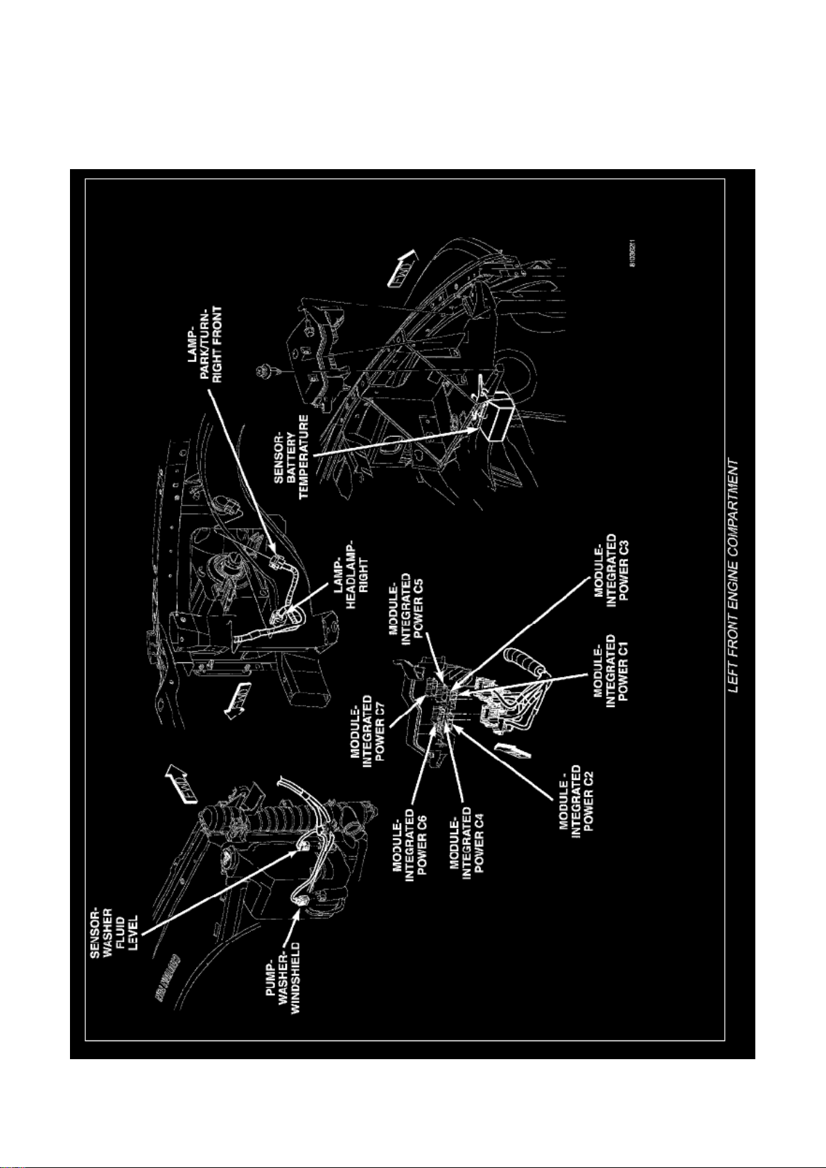
Dodge Ram Srt-10 Pickup Workshop Manual (V10-505 8.3L (2004))
Dodge Workshop Manuals > Relays and Modules > Relays and Modules - Power and Ground Distribution > Power
Distribution Module > Component Information > Locations
Page 92

Power Distribution Module: Locations
Left Front Engine Compartment
Page 93
Dodge Ram Srt-10 Pickup Workshop Manual (V10-505 8.3L (2004))
Dodge Workshop Manuals > Relays and Modules > Relays and Modules - Power and Ground Distribution > Power
Distribution Module > Component Information > Locations > Page 92
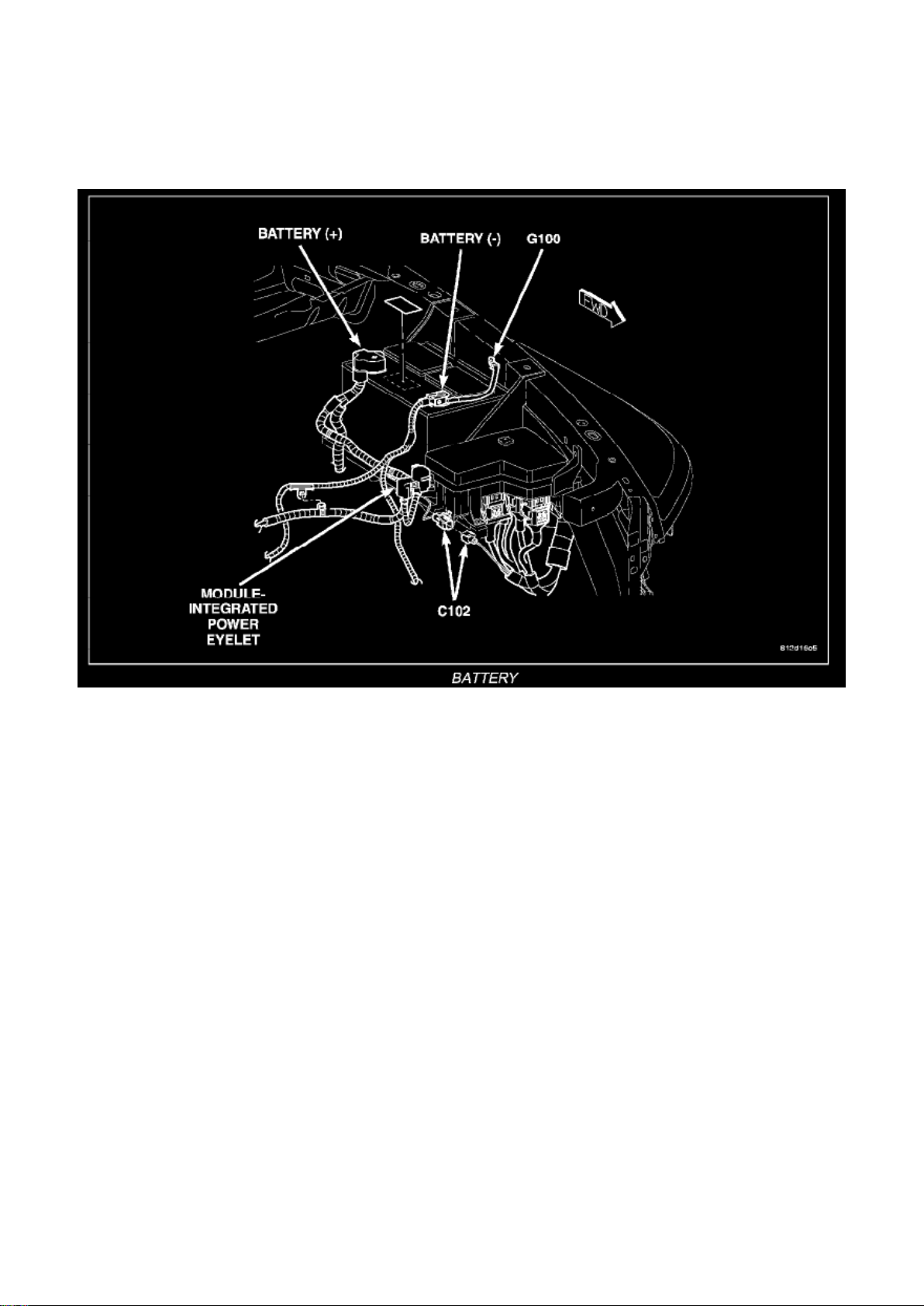
Battery
Page 94
Dodge Ram Srt-10 Pickup Workshop Manual (V10-505 8.3L (2004))
Dodge Workshop Manuals > Relays and Modules > Relays and Modules - Power and Ground Distribution > Power
Distribution Module > Component Information > Locations > Page 93
Page 95

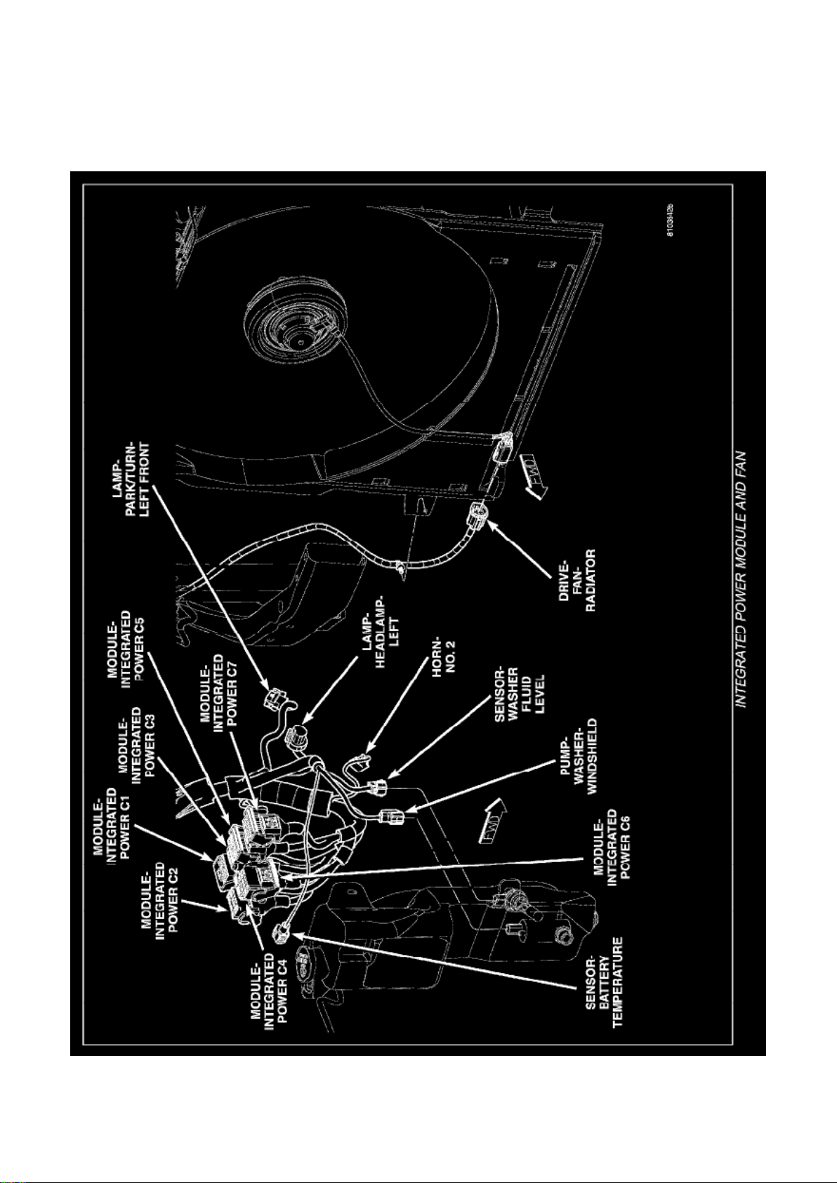
Integrated Power Module And Fan
Page 96
Dodge Ram Srt-10 Pickup Workshop Manual (V10-505 8.3L (2004))
Dodge Workshop Manuals > Relays and Modules > Relays and Modules - Power and Ground Distribution > Power
Distribution Module > Component Information > Locations > Page 94
Page 97

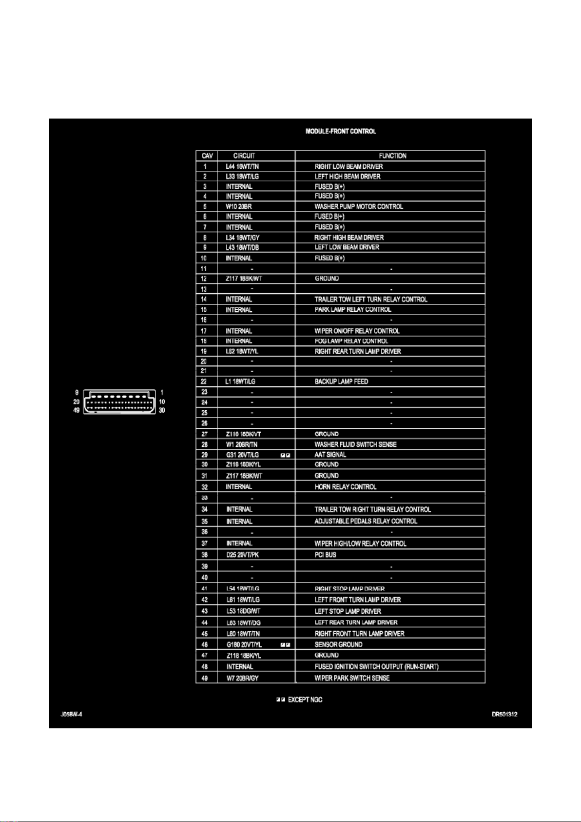
Power Distribution Module: Diagrams
8w-13-12
Page 98
Dodge Ram Srt-10 Pickup Workshop Manual (V10-505 8.3L (2004))
Dodge Workshop Manuals > Relays and Modules > Relays and Modules - Power and Ground Distribution > Power
Distribution Module > Component Information > Locations > Page 95
Page 99

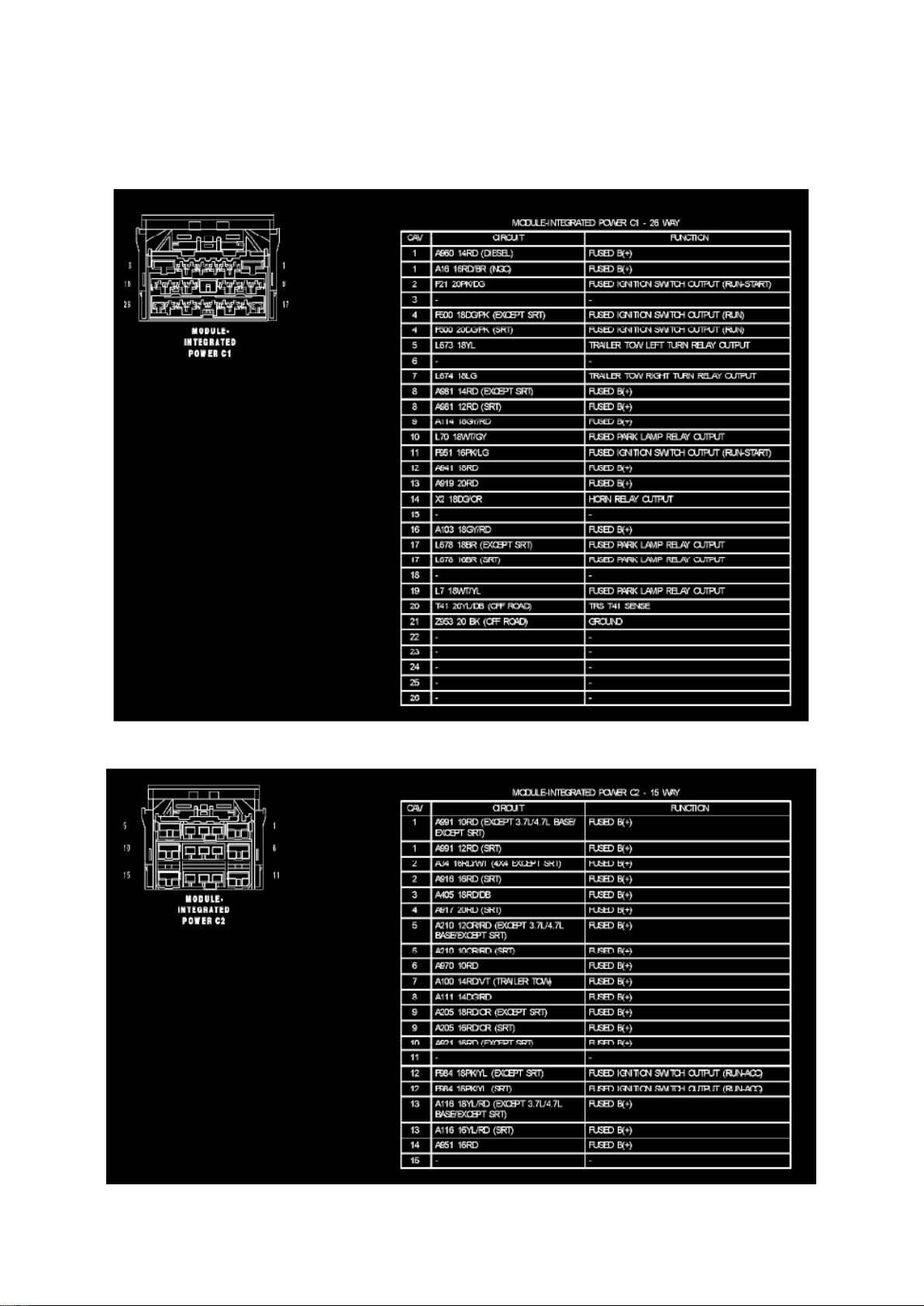
Module-Integrated Power C1
Module-Integrated Power C2
Page 100
Dodge Ram Srt-10 Pickup Workshop Manual (V10-505 8.3L (2004))
Dodge Workshop Manuals > Relays and Modules > Relays and Modules - Power and Ground Distribution > Power
Distribution Module > Component Information > Locations > Page 96
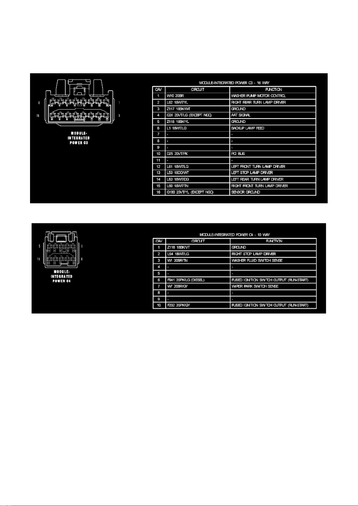
Module-Integrated Power C3
Module-Integrated Power C4
 Loading...