

Page 1
2014 ENGINE
DESCRIPTION
cylinder block at the transmission flange.
DESCRIPTION
CAUTION: If the engine has experienced a catastrophic failure, THE INTAKE
2014 RAM 1500 Laramie
2014 RAM 1500 Laramie
2014 ENGINE 3.6L - Service Information - Ram Pickup
2014 ENGINE 3.6L - Service Information - Ram Pickup
3.6L - Service Information - Ram Pickup
MANIFOLD MUST BE REPLACED!
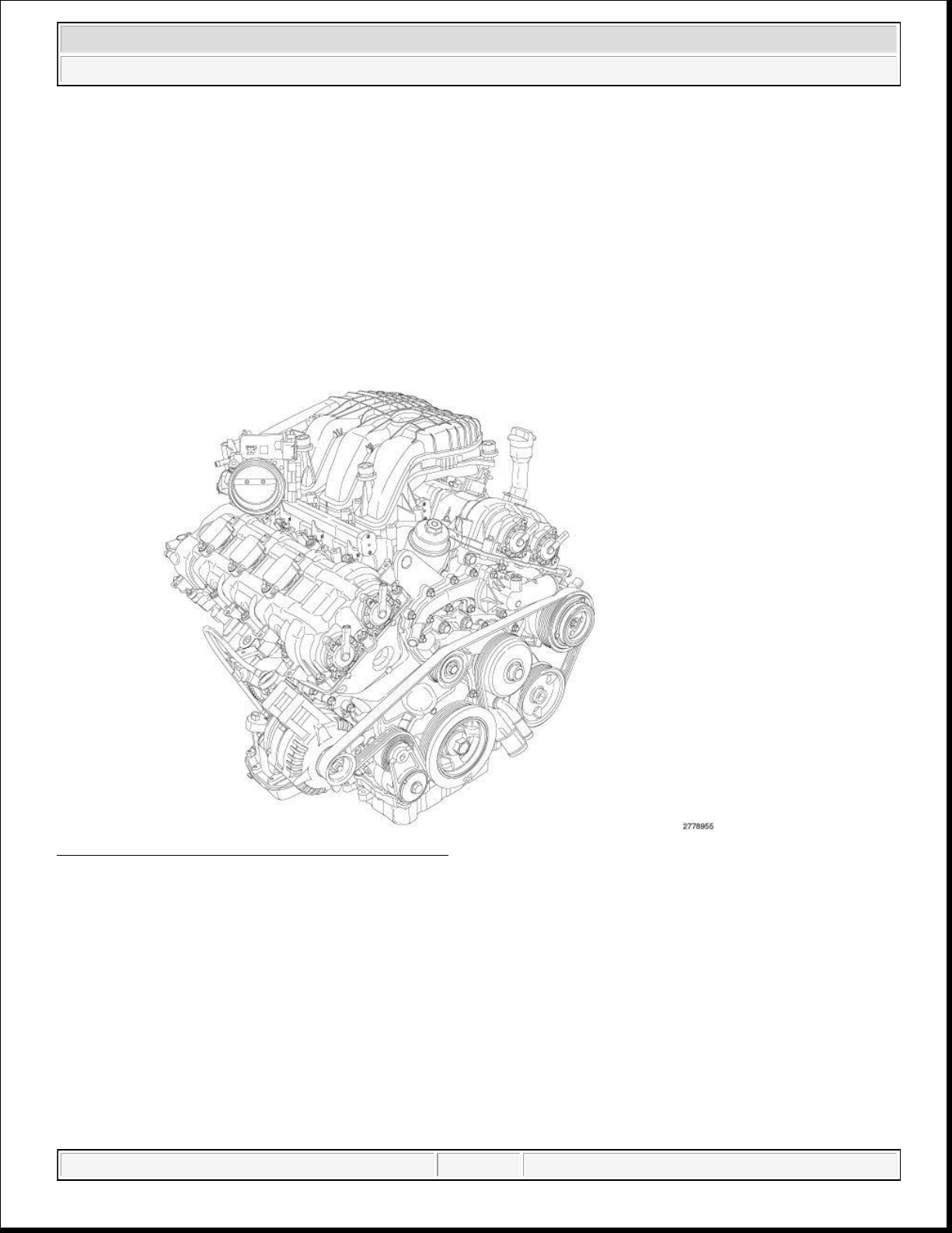
Fig. 1: 3.6L (219.7 CID) Flexible Fuel V-6 Engine
Courtesy of CHRYSLER GROUP, LLC
NOTE: Grand Cherokee (WK) engine shown in illustration, Wrangler (JK) and RAM 1500
(DS) engine similar.
The 3.6 liter (219.7 CID) flexible fuel V-6 engine features Variable Valve Timing (VVT), Dual Overhead
Camshafts (DOHC) and a high-pressure die-cast aluminum cylinder block with steel liners in a 60°
configuration. The 3.6 liter engine has a chain driven variable discharge oil pump with a two-stage pressure
regulator for improved fuel economy. The exhaust manifolds are integrated into the cylinder heads for reduced
weight. The cylinders are numbered from front to rear. The right bank is numbered 1, 3, 5 and the left bank is
numbered 2, 4, 6. The firing order is 1-2-3-4-5-6. The engine serial number is located on the left side of the
domingo, 10 de octubre de 2021 04:48:06 p. m. Page 1 © 2011 Mitchell Repair Information Company, LLC. domingo, 10 de octubre de 2021 04:48:20 p. m. Page 1 © 2011 Mitchell Repair Information Company, LLC.
Page 2
DIAGNOSIS AND TESTING
piston of the cylinder to be tested at TDC on the compression stroke.
2014 RAM 1500 Laramie
2014 ENGINE 3.6L - Service Information - Ram Pickup
ENGINE DIAGNOSIS - INTRODUCTION
This section can be helpful in determining the causes of malfunctions not detected and remedied by routine
maintenance.
These malfunctions are classified as Performance (e.g., engine idles rough and stalls) or Mechanical (e.g., a
strange noise).
Refer to the ENGINE PERFORMANCE DIAGNOSTIC TABLE and the ENGINE MECHANICAL
DIAGNOSTIC TABLE for possible causes and corrections of malfunctions. Refer to FUEL SYSTEM - 1500
for the fuel system diagnosis.
Additional diagnosis and testing procedures may be necessary for specific engine malfunctions that can not be
isolated with the Service Diagnosis charts. Information concerning additional tests and diagnosis is provided
within the following diagnosis:
Cylinder Compression Pressure Test: Refer to CYLINDER COMPRESSION PRESSURE
LEAKAGE .
Cylinder Combustion Pressure Leakage Test: Refer to CYLINDER LEAKAGE TEST .
Engine Cylinder Head Gasket Failure Diagnosis: Refer to CYLINDER HEAD GASKET .
Intake Manifold Leakage Diagnosis: Refer to DIAGNOSIS AND TESTING - INTAKE MANIFOLD
LEAKS .
CYLINDER LEAKAGE TEST
The combustion pressure leakage test provides an accurate means for determining engine condition.
Combustion pressure leakage testing will detect:
Exhaust and intake valve leaks (improper seating).
Leaks between adjacent cylinders or into water jacket.
1. Check the coolant level and fill as required. DO NOT install the radiator cap.
2. Start and operate the engine until it attains normal operating temperature.
3. Turn the engine OFF.
4. Remove the spark plugs.
5. Remove the oil filler cap.
6. Remove the air cleaner hose.
7. Calibrate the tester according to the manufacturer's instructions. The shop air source for testing
should maintain a regulated air pressure at 552 kPa (80 psi).
8. Perform the test procedures on each cylinder according to the tester manufacturer's instructions. Set the
domingo, 10 de octubre de 2021 04:48:06 p. m. Page 2 © 2011 Mitchell Repair Information Company, LLC.
Page 3
5.
Insert a compression pressure gauge and rotate the engine with the engine starter motor for three
2014 RAM 1500 Laramie
2014 ENGINE 3.6L - Service Information - Ram Pickup
9. As each cylinder is pressurized, listen for the air escaping through the throttle body, tailpipe and oil filler
cap opening. Check for bubbles in the radiator coolant.
All gauge pressure indications should be equal, with no more than 25% leakage.
If leakage is greater then 25%, refer to CYLINDER LEAKAGE DIAGNOSIS CHART below.
CYLINDER LEAKAGE DIAGNOSIS CHART
CONDITION POSSIBLE CAUSE CORRECTION
AIR ESCAPES THROUGH
THROTTLE BODY
Intake valve bent, burnt, or not
seated properly
Inspect valve and valve seat. Reface
or replace, as necessary. Inspect
valve springs. Replace as necessary.
AIR ESCAPES THROUGH
TAILPIPE
Exhaust valve bent, burnt, or not
seated properly
Inspect valve and valve seat. Reface
or replace, as necessary. Inspect
valve springs. Replace as necessary.
AIR ESCAPES THROUGH
RADIATOR
MORE THAN 50% LEAKAGE
FROM ADJACENT
CYLINDERS
MORE THAN 25% LEAKAGE
AND AIR ESCAPES THROUGH
OIL FILLER CAP OPENING
ONLY
Head gasket leaking or cracked
cylinder head or block
Head gasket leaking or crack in
cylinder head or block between
adjacent cylinders
Stuck or broken piston rings;
cracked piston; worn rings
and/or cylinder wall
Remove cylinder head and inspect.
Replace defective part
Remove cylinder head and inspect.
Replace gasket, head, or block as
necessary
Inspect for broken rings or piston.
Measure ring gap and cylinder
diameter, taper and out-of-round.
Replace defective part as necessary
CYLINDER COMPRESSION PRESSURE LEAKAGE
NOTE: To perform a compression test on a MULTI-AIR equipped engine, the ignition
MUST remain in the "key on" position. If the ignition is in the "off" position, the
intake valves will not actuate and the result will be no compression.
NOTE: The results of a cylinder compression pressure test can be utilized to diagnose
several engine malfunctions.
NOTE: Be certain the battery is completely charged and the engine starter motor is in
good operating condition. Otherwise the indicated compression pressures may
not be valid for diagnosis purposes.
1. Clean the spark plug recesses with compressed air.
2. Remove the spark plugs and record the cylinder number of each spark plug for future reference.
3. Inspect the spark plug electrodes for abnormal firing indicators such as fouled, hot, oily, etc.
4. Disable the fuel system and perform the fuel system pressure release procedure. Refer to FUEL
SYSTEM PRESSURE RELEASE .
domingo, 10 de octubre de 2021 04:48:06 p. m. Page 3 © 2011 Mitchell Repair Information Company, LLC.
Page 4
revolutions.
2014 RAM 1500 Laramie
2014 ENGINE 3.6L - Service Information - Ram Pickup
6. Record the compression pressure on the 3rd revolution. Continue the test for the remaining cylinders.
NOTE: The recommended compression pressures are to be used only as a guide
to diagnosing engine problems. An engine should not be disassembled to
determine the cause of low compression unless some malfunction is
present.
7. Compression should not be less than 689 kPa (100 psi) and not vary more than 25 percent from cylinder
to cylinder.
8. If one or more cylinders have abnormally low compression pressures, repeat the compression test.
NOTE: If the same cylinder or cylinders repeat an abnormally low reading on the
second compression test, it could indicate the existence of a problem in
the cylinder in question.
9. If one or more cylinders continue to have abnormally low compression pressures, perform the cylinder
combustion pressure leakage test. Refer to CYLINDER LEAKAGE TEST .
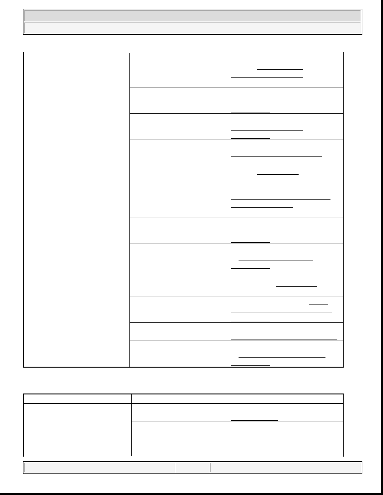
ENGINE LUBRICATION DIAGNOSTIC TABLE
CONDITION POSSIBLE CAUSES CORRECTION
OIL LEAKS 1. Gaskets and O-rings.
1. Replace as necessary.
Misaligned or damaged.
(a) Loose fasteners, broken or
porous metal parts.
(a) Tighten fasteners, Repair or
replace metal parts.
2. Crankshaft rear oil seal. 2. Replace rear crankshaft oil seal.
Refer to SEAL, CRANKSHAFT
OIL, REAR, REMOVAL.
3. Crankshaft seal flange.
3. Polish or replace crankshaft.
Scratched, nicked or grooved.
4. Oil pan flange cracked. 4. Replace oil pan. Refer to PAN,
OIL, REMOVAL .
5. Engine timing cover seal,
damaged or misaligned.
5. Replace seal. Refer to SEAL,
CRANKSHAFT OIL, FRONT,
REMOVAL .
6. Scratched or damaged
6. Polish or replace damper.
vibration damper hub.
OIL PRESSURE DROP 1. Low oil level. 1. Check and correct oil level.
2. Faulty oil pressure sensor. 2. Replace sensor. Refer to
SENSOR, OIL PRESSURE,
REMOVAL .
3. Low oil pressure. 3. Check main bearing clearance.
Refer to STANDARD
PROCEDURE .
domingo, 10 de octubre de 2021 04:48:06 p. m. Page 4 © 2011 Mitchell Repair Information Company, LLC.
Page 5
2014 RAM 1500 Laramie
2014 ENGINE 3.6L - Service Information - Ram Pickup
3. Check rod bearing clearance.
Refer to BEARING(S),
CONNECTING ROD,
STANDARD PROCEDURE.
4. Clogged oil filter. 4. Replace oil filter. Refer to
FILTER, ENGINE OIL,
REMOVAL .
5. Worn oil pump. 5. Replace oil pump. Refer to
PUMP, ENGINE OIL,
REMOVAL .
6. Thin or diluted oil. 6. Change oil and filter. Refer to
STANDARD PROCEDURE .
7. Excessive bearing clearance. 7. Replace crankshaft bearings.
Refer to STANDARD
PROCEDURE .
7. Replace rod bearings. Refer to
BEARING(S), CONNECTING
ROD, STANDARD
PROCEDURE.
8. Oil pump relief valve stuck. 8. Replace oil pump. Refer to
PUMP, ENGINE OIL,
REMOVAL .
9. Oil pump pick-up tube loose,
damaged or clogged.
9. Replace oil pump pick-up. Refer
to PICK-UP, OIL PUMP,
REMOVAL .
OIL PUMPING AT RINGS 1. Worn or damaged rings. 1. Hone cylinder bores and replace
rings. Refer to STANDARD
PROCEDURE .
2. Carbon in oil ring slots. 2. Replace rings. Refer to ROD,
PISTON AND CONNECTING,
REMOVAL .
3. Worn valve guides. 3. Replace cylinder heads. Refer to
CYLINDER HEAD, REMOVAL .
4. Leaking valve guide seals. 4. Replace valve guide seals. Refer
to SEAL(S), VALVE GUIDE,
REMOVAL .
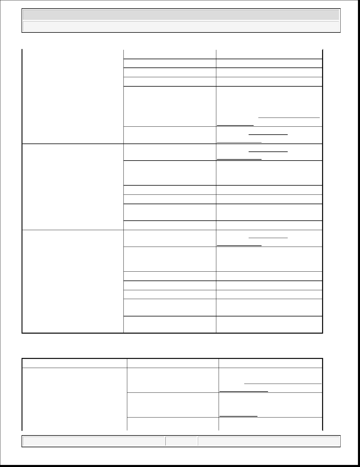
ENGINE MECHANICAL DIAGNOSTIC TABLE
CONDITION POSSIBLE CAUSES CORRECTIONS
NOISY VALVES 1. High or low oil level in
crankcase.
1. Refer to STANDARD
PROCEDURE .
2. Thin or diluted oil. 2. Change oil and filter.
3. Low oil pressure. 3. Check oil pump, if OK, check rod
and main bearings for excessive
domingo, 10 de octubre de 2021 04:48:06 p. m. Page 5 © 2011 Mitchell Repair Information Company, LLC.
Page 6
2014 RAM 1500 Laramie
2014 ENGINE 3.6L - Service Information - Ram Pickup
wear.
4. Dirt in lash adjusters. 4. Replace as necessary.
5. Worn rocker arms. 5. Replace as necessary.
6. Worn lash adjusters 6. Replace as necessary.
7. Worn valve guides. 7. Inspect the valve guides for wear,
cracks or looseness. If either
condition exists, replace the cylinder
head. Refer to CYLINDER HEAD,
REMOVAL .
8. Excessive runout of valve
seats on valve faces.
8. Refer to STANDARD
PROCEDURE .
CONNECTING ROD NOISE 1. Insufficient oil supply. 1. Refer to STANDARD
PROCEDURE .
2. Low oil pressure. 2. Check oil pump, if OK, check rod
and main bearings for excessive
wear.
3. Thin or diluted oil. 3. Change oil and filter.
4. Excessive bearing clearance. 4. Replace as necessary.
5. Connecting rod journal out-
5. Service or replace crankshaft.
of-round.
6. Misaligned connecting rods. 6. Replace bent connecting rods.
MAIN BEARING NOISE 1. Insufficient oil supply. 1. Refer to STANDARD
PROCEDURE .
2. Low oil pressure. 2. Check oil pump, if OK, check rod
and main bearings for excessive
wear.
3. Thin or diluted oil. 3. Change oil and filter.
4. Excessive bearing clearance. 4. Replace as necessary.
5. Excessive end play. 5. Check thrust washers for wear.
6. Crankshaft journal out-of
6. Service or replace crankshaft.
round.
7. Loose flywheel or torque
7. Tighten to correct torque
converter.
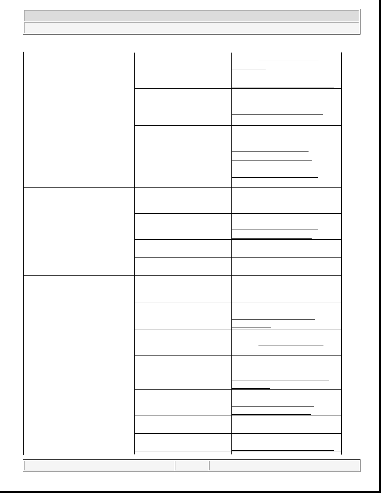
ENGINE PERFORMANCE DIAGNOSTIC TABLE
CONDITION POSSIBLE CAUSE CORRECTION
ENGINE WILL NOT START 1. Weak battery 1. Charge or replace as necessary.
Refer to BATTERY, DIAGNOSIS
AND TESTING .
2. Corroded or loose battery
connections.
2. Clean and tighten battery
connections. Refer to
CLEANING .
3. Faulty engine starting 3. Diagnose engine starting system.
domingo, 10 de octubre de 2021 04:48:06 p. m. Page 6 © 2011 Mitchell Repair Information Company, LLC.
Page 7
2014 RAM 1500 Laramie
2014 ENGINE 3.6L - Service Information - Ram Pickup
system. Refer to DIAGNOSIS AND
4. Faulty coil or control unit. 4. Replace ignition coil. Refer to
5. Incorrect spark plug gap. 5. Correct as necessary.
6. Incorrect cam timing. 6. Verify cam timing. Refer to
7. Dirt or water in fuel system. 7. Clean fuel system.
8. Faulty fuel pump or wiring. 8. Repair or replace as necessary.
9. Faulty Camshaft Position
(CMP) sensor.
10. Faulty Crankshaft Position
(CKP) sensor.
ENGINE STALLS OR ROUGH
1. Vacuum leak. 1. Inspect intake manifold and
IDLE
2. Faulty Crankshaft Position
(CKP) sensor.
3. Faulty ignition coil. 3. Replace ignition coil. Refer to
4. Incorrect cam timing. 4. Verify cam timing. Refer to
ENGINE LOSS OF POWER 1. Dirty or incorrectly gapped
spark plugs.
2. Dirt or water in fuel system. 2. Clean fuel system.
3. Faulty fuel pump. 3. Replace fuel pump. Refer to
4. Leaking cylinder head
gasket.
5. Low compression. 5. Determine the cause and repair
6. Burned, warped or pitted
valves.
7. Plugged or restricted exhaust
system.
8. Faulty ignition coil. 8. Replace ignition coil. Refer to
TESTING .
COIL, IGNITION, REMOVAL .
STANDARD PROCEDURE .
9. Replace sensor. Refer to
SENSOR, CAMSHAFT
POSITION, REMOVAL .
10. Replace sensor. Refer to
SENSOR, CRANKSHAFT
POSITION, REMOVAL .
vacuum hoses, repair or replace as
necessary.
2. Replace sensor. Refer to
SENSOR, CRANKSHAFT
POSITION, REMOVAL .
COIL, IGNITION, REMOVAL .
STANDARD PROCEDURE .
1. Correct as necessary. Refer to
SPARK PLUG, REMOVAL .
MODULE, FUEL PUMP,
REMOVAL .
4. Replace cylinder head gasket.
Refer to CYLINDER HEAD,
REMOVAL .
as necessary. Refer to CYLINDER
COMPRESSION PRESSURE
LEAKAGE .
6. Replace as necessary. Refer to
VALVES, INTAKE AND
EXHAUST, REMOVAL .
7. Inspect and replace as necessary.
COIL, IGNITION, REMOVAL .
domingo, 10 de octubre de 2021 04:48:06 p. m. Page 7 © 2011 Mitchell Repair Information Company, LLC.
Page 8
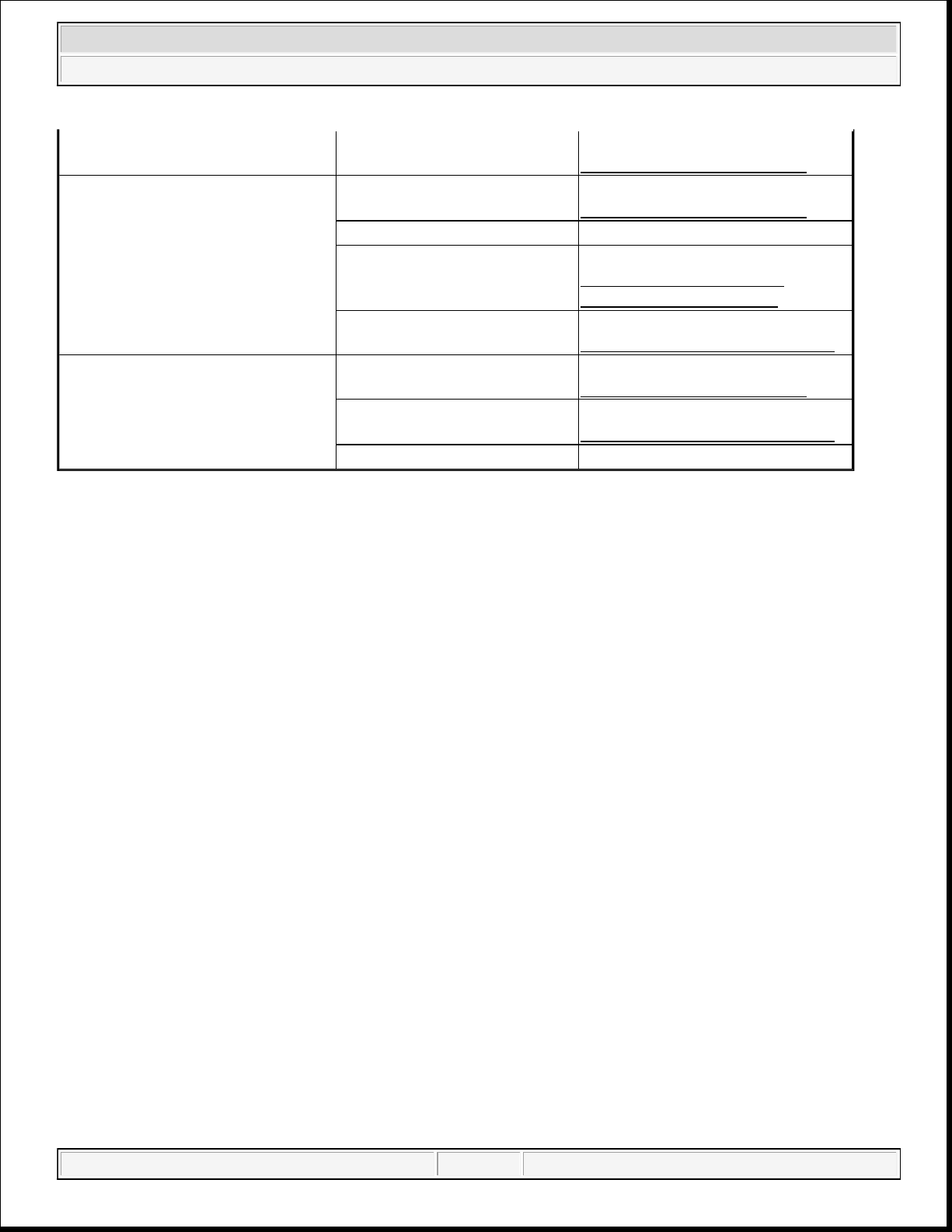
ENGINE MISSES ON
ACCELERATION
ENGINE MISSES AT HIGH
SPEED
2014 RAM 1500 Laramie
2014 ENGINE 3.6L - Service Information - Ram Pickup
9. Incorrect cam timing. 9. Verify cam timing. Refer to
STANDARD PROCEDURE .
1. Dirty or incorrectly gapped
spark plugs.
1. Correct as necessary. Refer to
SPARK PLUG, REMOVAL .
2. Dirt in fuel system. 2. Clean fuel system.
3. Burned, warped or pitted
valves.
3. Replace as necessary. Refer to
VALVES, INTAKE AND
EXHAUST, REMOVAL .
4. Faulty ignition coil. 4. Replace ignition coil. Refer to
COIL, IGNITION, REMOVAL .
1. Dirty or incorrectly gapped
spark plugs.
1. Correct as necessary. Refer to
SPARK PLUG, REMOVAL .
4. Faulty ignition coil. 2. Replace ignition coil. Refer to
COIL, IGNITION, REMOVAL .
3. Dirt or water in fuel system. 3. Clean fuel system.
OIL CONSUMPTION TEST AND DIAGNOSIS
The following diagnostic procedures are used to determine the source of excessive internal oil consumption,
these procedures and tests apply to vehicles with 50, 000 miles or less.
NOTE: Engine oil consumption may be greater than normal during engine break-in.
Repairs should be delayed until vehicle has been driven at least 7, 500 miles.
Severe service (high ambient temperature, short trips, heavy loading, trailer towing, taxi, off-road, or law
enforcement use) may result in greater oil consumption than normal.
Sustained high speed driving and high engine RPM operation may result in increased oil consumption.
Failure to comply with the recommended oil type and viscosity rating, as outlined in the owner's manual,
may impact oil economy as well as fuel economy.
Oil consumption may increase with vehicle age and mileage due to normal engine wear.
NOTE: Because a few drops of external oil leakage per mile can quickly account for the
loss of one quart of oil in a few hundred miles, be certain there is no external
engine oil leaks present.
Oil leakage is not the same as oil consumption and all external leakage must be eliminated before
any action can be taken to verify and/or correct oil consumption complaints.
Verify that the engine has the correct oil level dipstick and dipstick tube installed.
Verify that the engine is not being run in an overfilled condition. Check the oil level 15 minutes
after a hot shutdown with the vehicle parked on a level surface. In no case should the level be above
MAX or the FULL mark on the dipstick.
domingo, 10 de octubre de 2021 04:48:06 p. m. Page 8 © 2011 Mitchell Repair Information Company, LLC.
Page 9
OIL CONSUMPTION TEST
3.
Improper operation of "PCV "system
2014 RAM 1500 Laramie
2014 ENGINE 3.6L - Service Information - Ram Pickup
1. Check the oil level at least 15 minutes after a hot shutdown.
2. If the oil level is low, top off with the proper viscosity and API service level engine oil. Add one bottle of
MOPAR® 4-In-1 Leak Detection Dye into the engine oil.
3. Tamper proof the oil pan drain plug, oil filter, dipstick and oil fill cap.
4. Record the vehicle mileage.
5. Instruct the customer to drive the vehicle as usual.
6. Ask the customer to return to the servicing dealer after accumulating 500 miles, Check the oil level at
least 15 minutes after a hot shutdown. If the oil level is half way between the "FULL" and "ADD" mark
continue with the next step.
7. Using a black light, recheck for any external engine oil leaks, repair as necessary. If no external engine oil
leaks are present, continue with oil consumption diagnosis.
OIL CONSUMPTION DIAGNOSIS
1. Check the positive crankcase ventilation (PCV) system. Make sure the system is not restricted and the
PCV valve has the correct part number and correct vacuum source (18-20 in. Hg at idle below 3000 ft.
above sea level is considered normal).
2. Perform a cylinder compression test and cylinder leak down test using the standard leak down gauge
following manufacturers suggested best practices.
NOTE: Verify the spark plugs are not oil saturated. If the spark plugs are oil
saturated and compression is good it can be assumed the valve seals or
valve guides are at fault.
3. If one or more cylinders have more than 15% leak down further engine tear down and inspection will be
required.
TOP 19 REASONS THAT MAY LEAD TO ENGINE OIL CONSUMPTION
1. Tapered and Out-of-Round Cylinders
The increased piston clearances permit the pistons to rock in the worn cylinders. While tilted
momentarily, an abnormally large volume of oil is permitted to enter on one side of the piston. The rings,
also tilted in the cylinder, permit oil to enter on one side. Upon reversal of the piston on each stroke, some
of this oil is passed into the combustion chamber.
2. Distorted Cylinders
This may be caused by unequal heat distribution or unequal tightening of cylinder head bolts. This
condition presents a surface which the rings may not be able to follow completely. In this case, there may
be areas where the rings will not remove all of the excess oil. When combustion takes place, this oil will
be burned and cause high oil consumption.
domingo, 10 de octubre de 2021 04:48:06 p. m. Page 9 © 2011 Mitchell Repair Information Company, LLC.
Page 10
The main purpose of the Positive Crankcase Ventilation (PCV) valve is to recirculate blow
-
by gases back
2014 RAM 1500 Laramie
2014 ENGINE 3.6L - Service Information - Ram Pickup
from the crankcase area through the engine to consume unburned hydrocarbons. The PCV system usually
has a one way check valve and a make up air source. The system uses rubber hoses that route crankcase
blow by gases to the intake manifold. Vacuum within the engine intake manifold pulls the blow by gases
out of the crankcase into the combustion chamber along with the regular intake air and fuel mixture.
The PCV system can become clogged with sludge and varnish deposits and trap blow by gases in the
crankcase. This degrades the oil, promoting additional formation of deposit material. If left uncorrected,
the result is plugged oil rings, oil consumption, rapid ring wear due to sludge buildup, ruptured gaskets
and seals due to crankcase pressurization.
4. Worn Piston Ring Grooves
For piston rings to form a good seal, the sides of the ring grooves must be true and flat - not flared or
shouldered. Piston rings in tapered or irregular grooves will not seal properly and, consequently, oil will
pass around behind the rings into the combustion chamber.
5. Worn, Broken or Stuck Piston Rings
When piston rings are broken, worn or stuck to such an extent that the correct tension and clearances are
not maintained, this will allow oil to be drawn into the combustion chamber on the intake stroke and hot
gases of combustion to be blown down the cylinder past the piston on the power stroke. All of these
conditions will result in burning and carbon build up of the oil on the cylinders, pistons and rings.
6. Cracked or Broken Ring Lands
Cracked or broken ring lands prevent the rings from seating completely on their sides and cause oil
pumping. This condition will lead to serious damage to the cylinders as well as complete destruction of
the pistons and rings. Cracked or broken ring lands cannot be corrected by any means other than piston
replacement.
7. Worn Valve Stems and Guides
When wear has taken place on valve stems and valve guides, the vacuum in the intake manifold will draw
oil and oil vapor between the intake valve stems and guides into the intake manifold and then into the
cylinder where it will be burned.
8. Bent or Misaligned Connecting Rods
Bent or misaligned connecting rods will not allow the pistons to ride straight in the cylinders. This will
prevent the pistons and rings from forming a proper seal with the cylinder walls and promote oil
consumption. In addition, it is possible that a bearing in a bent connect rod will not have uniform
clearance on the connecting rod wrist pin. Under these conditions, the bearing will wear rapidly and
throw off an excessive amount of oil into the cylinder.
9. Fuel Dilution
If raw fuel is allowed to enter the lubrication system, the oil will become thinner and more volatile and
domingo, 10 de octubre de 2021 04:48:06 p. m. Page 10 © 2011 Mitchell Repair Information Company, LLC.
Page 11
will result in higher oil consumption. The following conditions will lead to higher oil consumption;
Increasing performance through the use of performance/power enhancement products to a stock or factory
Lugging is running the engine at a lower RPM in a condition where a higher RPM (more power/torque)
2014 RAM 1500 Laramie
2014 ENGINE 3.6L - Service Information - Ram Pickup
Excess fuel can enter and mix with the oil via a leaking fuel injector
Gasoline contaminated with diesel fuel
Restricted air intake
Excessive idling
10. Contaminated Cooling Systems
Corrosion, rust, scale, sediment or other formations in the water jacket and radiator will prevent a cooling
system from extracting heat efficiently. This is likely to cause cylinder distortion thus leading to higher
oil consumption.
11. Oil Viscosity
The use of oil with a viscosity that is too light may result in high oil consumption. Refer to the vehicle
owner's manual for the proper oil viscosity to be used under specific driving conditions and/or ambient
temperatures.
12. Dirty Engine Oil
Failure to change the oil and filter at proper intervals may cause the oil to be so dirty that it will promote
accumulation of sludge and varnish and restrict oil passages in the piston rings and pistons. This will
increase oil consumption; dirty oil by nature is also consumed at a higher rate than clean oil.
13. Crankcase Overfull
Due to an error in inserting the oil dip stick so that it does not come to a seat on its shoulder, a low
reading may be obtained. Additional oil may be added to make the reading appear normal with the stick
in this incorrect position which will actually make the oil level too high. If the oil level is so high that the
lower ends of the connecting rods touch the oil in the oil pan excessive quantities of oil will be thrown on
the cylinder walls and some of it will work its way up into the combustion chamber.
14. Excessively High Oil Pressure
A faulty oil pressure relief valve may cause the oil pressure to be too high. The result will be that the
engine will be flooded with an abnormally large amount of oil in a manner similar to that which occurs
with worn bearings. This condition may also cause the oil filter to burst.
15. Aftermarket Performance Chips and Modification
engine will increase the chance of excessive oil consumption.
16. Lugging Engine
domingo, 10 de octubre de 2021 04:48:06 p. m. Page 11 © 2011 Mitchell Repair Information Company, LLC.
Page 12
should be implemented. Especially susceptible on vehicles equipped with a manual transmission. This
Courtesy of CHRYSLER GROUP, LLC
2014 RAM 1500 Laramie
2014 ENGINE 3.6L - Service Information - Ram Pickup
driving habit causes more stress loading on the piston and can lead to increases in engine oil
consumption.
17. Turbocharged Engines
There is a possibility for PCV "push-over" due to higher crankcase pressure (as compared to naturally
aspirated engines) which is normal for turbocharged engines. This condition causes varying amounts of
engine oil to enter the intake manifold, charge air cooler and associated plumbing to and from the charge
air cooler, also a leaking turbocharger seal will draw oil into the combustion chamber where it will burn
(blue smoke from tail pipe may be present) and form carbon deposits which contribute to further oil
consumption as they interfere with proper engine function.
18. Restricted Air Intake
Excessive restriction in the air intake system will increase engine vacuum and can increase oil
consumption, an extremely dirty air filter would be one example of this situation.
19. Intake Manifold port seals
Engines that have a "V" configuration and a "wet valley" (3.3/3.8L) could draw oil into the intake ports
due to improper sealing between the intake manifold ports and cylinder head. Causes may include
improper torque of intake manifold bolts, corrosion (aluminum intake manifold) and or warped sealing
surface.
STANDARD PROCEDURE
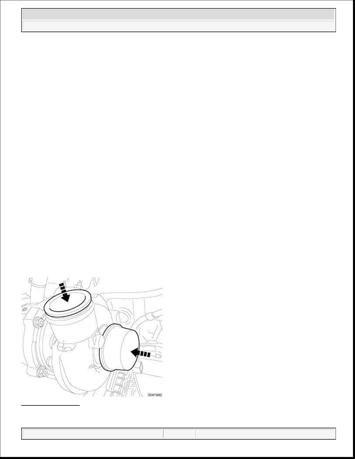
DUST COVERS AND CAPS
Fig. 2: Covers/Caps
domingo, 10 de octubre de 2021 04:48:06 p. m. Page 12 © 2011 Mitchell Repair Information Company, LLC.
Page 13
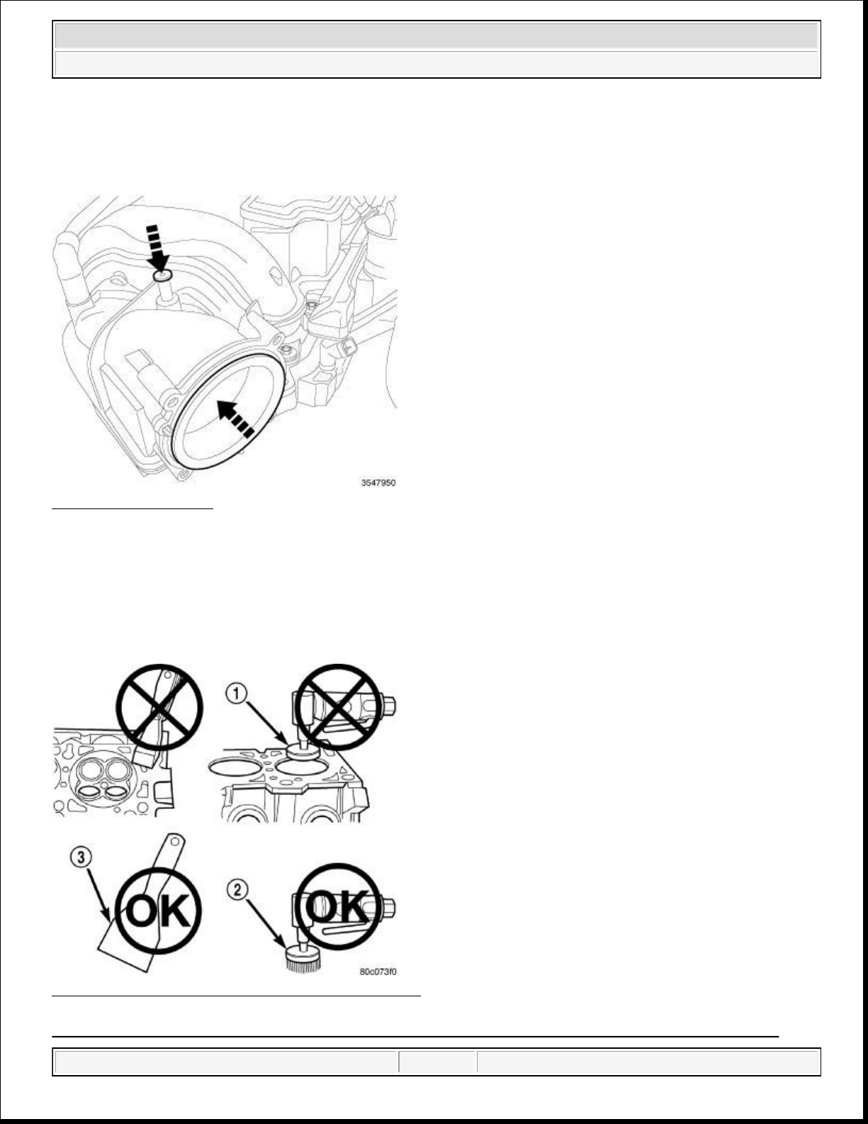
Due to the high amounts of failures caused by dust, dirt, moisture and other foreign debris being introduced to
2014 RAM 1500 Laramie
2014 ENGINE 3.6L - Service Information - Ram Pickup
the engine during service. Covers or caps are needed to reduce the possible damage that can be caused or
created.
Fig. 3: Opening Cover
Courtesy of CHRYSLER GROUP, LLC
Covers over openings will reduce any possibilities for foreign materials to enter the engine systems. Using
miller tool (special tool #10368, Set, Universal Protective Cap), Select the appropriated cover needed to the
procedure.
ENGINE GASKET SURFACE PREPARATION
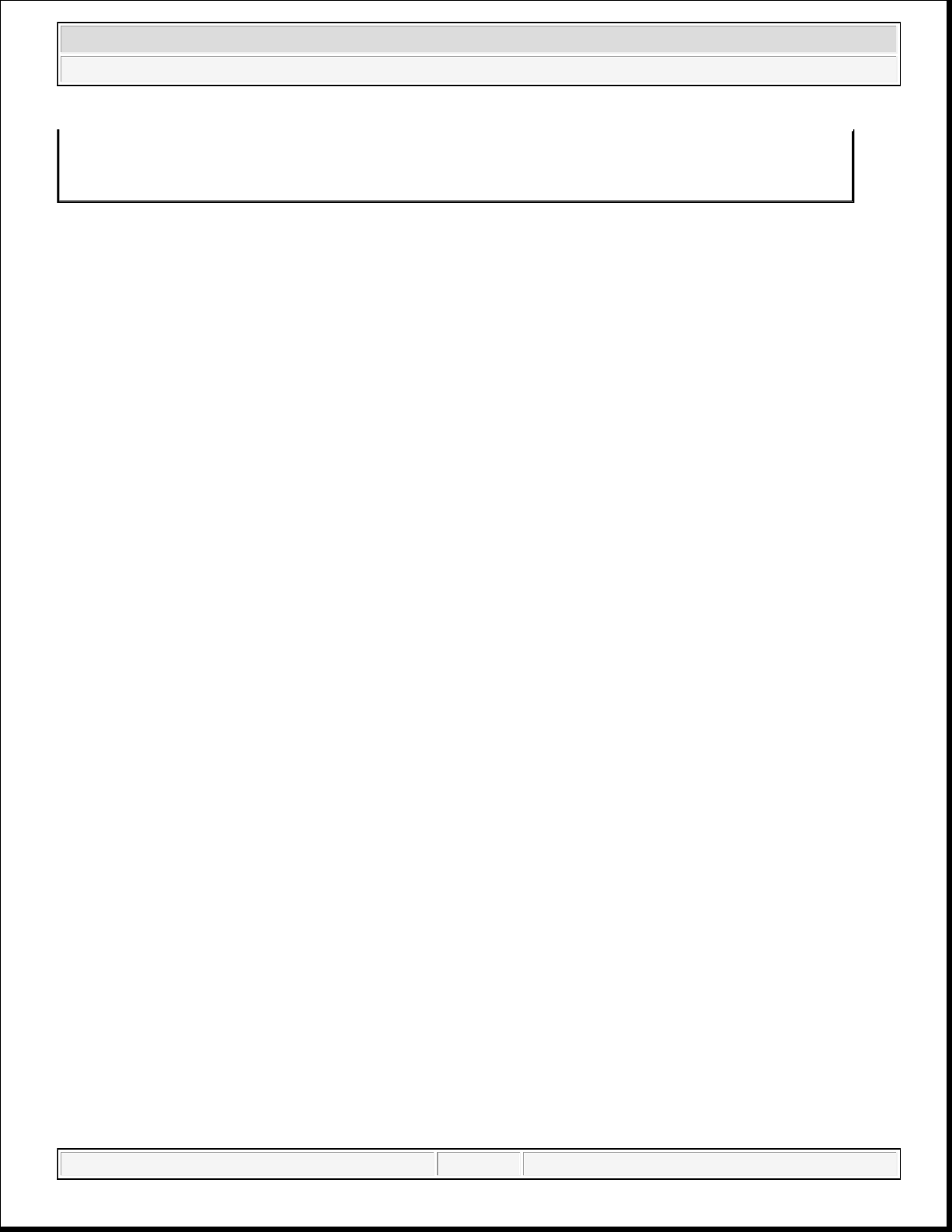
Fig. 4: Proper Tool Usage For Surface Preparation
Courtesy of CHRYSLER GROUP, LLC
domingo, 10 de octubre de 2021 04:48:06 p. m. Page 13 © 2011 Mitchell Repair Information Company, LLC.
Page 14
2014 RAM 1500 Laramie
2014 ENGINE 3.6L - Service Information - Ram Pickup
1 - ABRASIVE PAD
2 - 3M ROLOC™ BRISTLE DISC
3 - PLASTIC/WOOD SCRAPER
To ensure engine gasket sealing, proper surface preparation must be performed, especially with the use of
aluminum engine components and multi-layer steel cylinder head gaskets.
Never use the following to clean gasket surfaces:
Metal scraper.
Abrasive pad or paper to clean cylinder block and head.
High speed power tool with an abrasive pad or a wire brush (1).
NOTE: Multi-Layer Steel (MLS) head gaskets require a scratch free sealing surface.
Only use the following for cleaning gasket surfaces:
Solvent or a commercially available gasket remover
Plastic or wood scraper (3).
Drill motor with 3M Roloc™ Bristle Disc (white or yellow) (2).
CAUTION: Excessive pressure or high RPM (beyond the recommended speed), can
damage the sealing surfaces. The mild (white, 120 grit) bristle disc is
recommended. If necessary, the medium (yellow, 80 grit) bristle disc may
be used on cast iron surfaces with care.
FORM-IN-PLACE GASKETS AND SEALERS
NOTE: All of the sealants mentioned below are not used on every engine, they are
listed as a general reference guide. See service information for specific sealer
usage.
There are numerous places where form-in-place gaskets are used on the engine. Care must be taken when
applying form-in-place gaskets to assure obtaining the desired results.Do not use form-in-place gasket
material unless specified. Bead size, continuity, and location are of great importance. Too thin a bead can
result in leakage while too much can result in spill-over which can break off and obstruct fluid feed lines. A
continuous bead of the proper width is essential to obtain a leak-free gasket. All sealing surfaces that use formin-place gaskets and sealers must be free of grease or oil. Surfaces should be cleaned with Mopar® brake parts
cleaner prior to sealer application. After the sealer is applied, the parts should be assembled within 10 minutes.
There are numerous types of form-in-place gasket materials that are used in the engine area. Mopar® Engine
RTV GEN II, Mopar® ATF-RTV, and Mopar® Gasket Maker gasket materials, each have different properties
and can not be used in place of the other.
MOPAR® ENGINE RTV GEN II is used to seal components exposed to engine oil. This material is a
domingo, 10 de octubre de 2021 04:48:06 p. m. Page 14 © 2011 Mitchell Repair Information Company, LLC.
Page 15
specially designed black silicone rubber RTV that retains adhesion and sealing properties when exposed to
joint locations, a 3.17 or 6.35 mm (1/8 or 1/4 in.) drop is placed in the center of the gasket contact area.
2014 RAM 1500 Laramie
2014 ENGINE 3.6L - Service Information - Ram Pickup
engine oil. Moisture in the air causes the material to cure. This material is available in three ounce tubes and has
a shelf life of one year. After one year this material will not properly cure. Always inspect the package for the
expiration date before use.
MOPAR® ATF RTV is a specifically designed black silicone rubber RTV that retains adhesion and sealing
properties to seal components exposed to automatic transmission fluid, engine coolants, and moisture. This
material is available in three ounce tubes and has a shelf life of one year. After one year this material will not
properly cure. Always inspect the package for the expiration date before use.
MOPAR® GASKET MAKER is an anaerobic type gasket material. The material cures in the absence of air
when squeezed between two metallic surfaces. It will not cure if left in the uncovered tube. The anaerobic
material is for use between two machined surfaces. Do not use on flexible metal flanges.
MOPAR® BED PLATE SEALANT is a unique (green-in-color) anaerobic type gasket material that is
specially made to seal the area between the bed plate and cylinder block without disturbing the bearing
clearance or alignment of these components. The material cures slowly in the absence of air when torqued
between two metallic surfaces, and will rapidly cure when heat is applied.
MOPAR® THREEBOND ENGINE RTV SEALANT is a unique gasket material that is specially made to
retain adhesion and sealing properties when used to seal components exposed to engine oil.
SEALER APPLICATION
Mopar® Gasket Maker material should be applied sparingly 1 mm (0.040 in.) diameter or less of sealant to one
gasket surface. Be certain the material surrounds each mounting hole. Excess material can easily be wiped off.
Components should be torqued in place within 15 minutes. The use of a locating dowel is recommended during
assembly to prevent smearing material off the location.
Mopar® Engine RTV GEN II or ATF RTV gasket material should be applied in a continuous bead
approximately 3 mm (0.120 in.) in diameter. All mounting holes must be circled. For corner sealing and "T"
Uncured sealant may be removed with a shop towel. Components should be torqued in place while the sealant is
still wet to the touch (within 10 minutes). The usage of a locating dowel is recommended during assembly to
prevent smearing material off the location.
Mopar® Threebond Engine RTV Sealant gasket material should be applied in a continuous bead approximately
3 mm (0.120 in.) in diameter. The gasket surfaces should be cleaned with isopropyl alcohol wipes in preparation
for sealant application. All mounting holes must be circled. For corner sealing and "T" joint locations, a 3.17 or
6.35 mm (1/8 or 1/4 in.) drop is placed in the center of the gasket contact area. Uncured sealant may be removed
with a shop towel. Components should be assembled within 20 minutes and torqued in place within 45 minutes.
The usage of a locating dowel is recommended during assembly to prevent smearing material off the location.
REPAIR DAMAGED OR WORN THREADS
CAUTION: Be sure that the tapped holes maintain the original center line.
domingo, 10 de octubre de 2021 04:48:06 p. m. Page 15 © 2011 Mitchell Repair Information Company, LLC.
Page 16
Damaged or worn threads can be repaired. Essentially, this repair consists of:
2014 RAM 1500 Laramie
2014 ENGINE 3.6L - Service Information - Ram Pickup
Drilling out worn or damaged threads.
Tapping the hole with a special Heli-Coil Tap, or equivalent.
Installing an insert into the tapped hole to bring the hole back to its original thread size.
SPECIFICATIONS
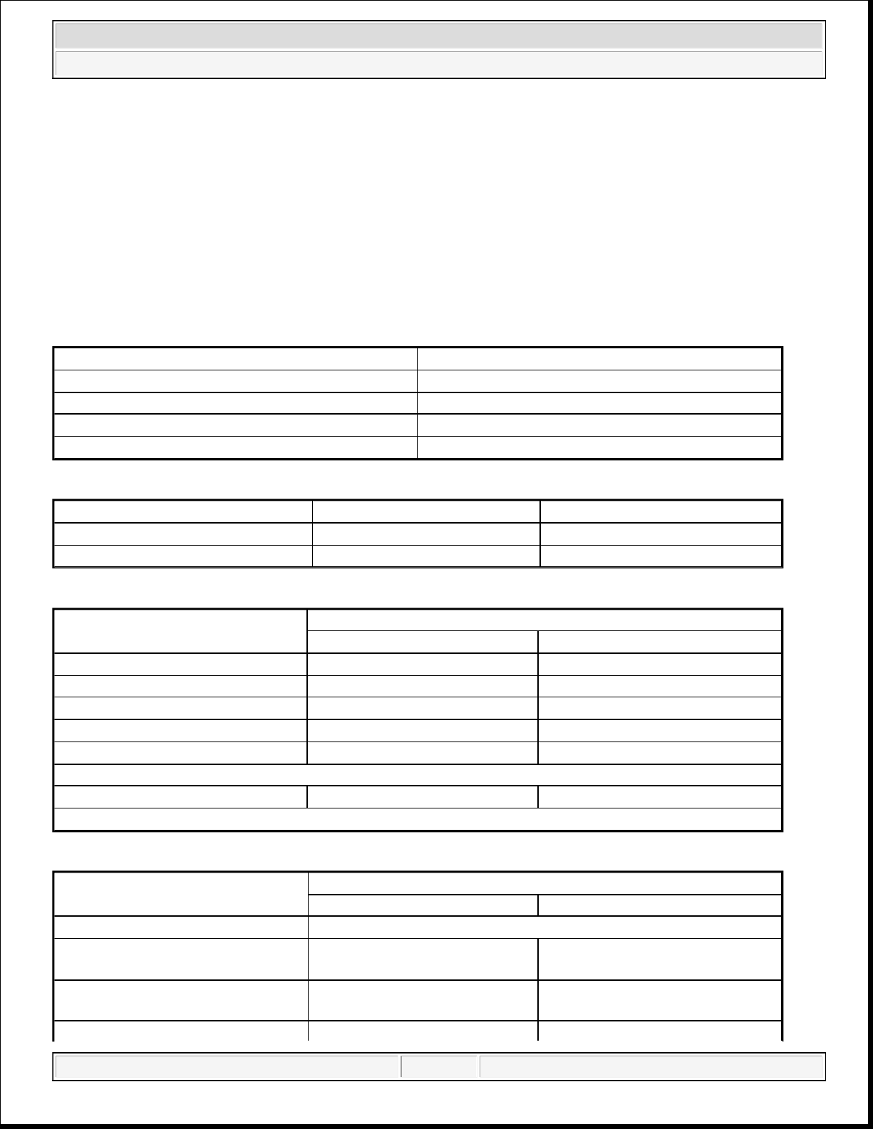
ENGINE SPECIFICATIONS
GENERAL SPECIFICATIONS (1 OF 2)
Description Specification
Type 60° DOHC V-6 24-Valve
Compression Ratio 10.2:1
Lead Cylinder #1 Right Bank
Firing Order 1-2-3-4-5-6
GENERAL SPECIFICATIONS (2 OF 2)
Description Metric Standard
Displacement 3.6 Liters 220 Cubic Inches
Bore and Stroke 96.0 x 83.0 mm 3.779 in. x 3.268 in.
CYLINDER BLOCK
Description
Metric Standard
Specification
Cylinder Bore Diameter - Grade 1 95.995 mm ± 0.005 mm 3.7793 in. ± 0.0002 in.
Cylinder Bore Diameter - Grade 2 96.005 mm ± 0.005 mm 3.7797 in. ± 0.0002 in.
Cylinder Bore Out-of-Round (Max.) 0.009 mm 0.00035 in.
Cylinder Bore Cylindricity 0.014 mm 0.0006 in.
Crankshaft Bore Taper* (Max.) 0.006 mm 0.0002 in.
*Measured over length of bulkhead
Engine Oil Galley Plug** 0.0 mm - 2.0 mm 0.0 in - 0.0787 in
**Measured proud of machined surface
PISTONS
Description
Metric Standard
Specification
Material Cast Aluminum Alloy
Piston Diameter (Metal to Metal) -
Grade 1
Piston Diameter (Metal to Metal) -
Grade 2
95.955 mm ± 0.005 mm 3.7778 in. ± 0.0002 in.
95.965 mm ± 0.005 mm 3.7781 in. ± 0.0002 in.
domingo, 10 de octubre de 2021 04:48:06 p. m. Page 16 © 2011 Mitchell Repair Information Company, LLC.
Page 17
2014 RAM 1500 Laramie
2014 ENGINE 3.6L - Service Information - Ram Pickup
Piston Diameter (Metal to Coating)
- Grade 1
Piston Diameter (Metal to Coating)
- Grade 2
Clearance at Size Location (Metal
to Metal)
Clearance at Size Location (Metal
to Coating)
95.970 - 96.000 mm 3.7783 - 3.7795 in.
95.980 - 96.010 mm 3.7787 - 3.7835 in.
0.030 - 0.050 mm 0.0012 - 0.0020 in.
0.010 - 0.030 mm 0.0004 - 0.0012 in.
Piston Weight 354 - 364 grams 12.487 - 12.840 oz.
Piston Pin Offset 0.8 mm 0.031 in.
Piston Ring Groove Diameter - No.
1
Piston Ring Groove Diameter - No.
2
Piston Ring Groove Diameter - No.
3
88.24 - 88.44 mm 3.474 - 3.482 in.
86.54 - 86.74 mm 3.407 - 3.415 in.
89.16 - 89.36 mm 3.510 - 3.518 in.
PISTON PINS
Description
Metric Standard
Specification
Type Full Floating
Pin Diameter 21.9985 ± 0.0015 mm 0.86608 ± 0.00006 in.
Clearance in Piston 0.002 - 0.011 mm 0.0001 - 0.0004 in.
Clearance in Rod 0.011 - 0.024 mm 0.0004 - 0.0009 in.
PISTON RINGS
Description
Metric Standard
Specification
Ring Gap - Number 1 Ring (Top) 0.25 - 0.40 mm 0.010 - 0.016 in.
Ring Gap - Number 2 Ring (Center) 0.30 - 0.45 mm 0.012 - 0.018 in.
Ring Gap - Oil Control Ring (Steel
Rails)
0.15 - 0.66 mm 0.006 - 0.026 in.
PISTON RING SIDE CLEARANCE
Description
Metric Standard
Specification
Number 1 Ring (Top) 0.025 - 0.083 mm 0.0010 - 0.0033 in.
Number 2 Ring (Center) 0.030 - 0.078 mm 0.0012 - 0.0031 in.
Oil Control Ring (Steel Rails) 0.007 - 0.173 mm 0.0003 - 0.0068 in.
PISTON RING WIDTH
Description
domingo, 10 de octubre de 2021 04:48:06 p. m. Page 17 © 2011 Mitchell Repair Information Company, LLC.
Metric Standard
Specification
Page 18
2014 RAM 1500 Laramie
2014 ENGINE 3.6L - Service Information - Ram Pickup
Number 1 Ring (Top) 3.00 - 3.20 mm 0.118 - 0.126 in.
Number 2 Ring (Center) 3.59 - 3.85 mm 0.141 - 0.152 in.
Oil Control Ring (Steel Rails) 1.930 - 2.083 mm 0.076 - 0.082 in.
CONNECTING RODS
Description
Metric Standard
Specification
Bearing Clearance (With Crush) 0.023 - 0.064 mm 0.0009 - 0.0025 in.
Side Clearance 0.070 - 0.370 mm 0.0028 - 0.0146 in.
Side Clearance (Max.) 0.370 mm 0.0146 in.
Piston Pin Bore Diameter 22.016 ± 0.005 mm 0.8668 ± 0.0002 in.
Bearing Bore Out of Round (Max.) 0.008 mm 0.0003 in.
Total Weight (Less Bearing) 546.7 ± 8 grams 19.28 ± 0.28 oz.
CRANKSHAFT MAIN BEARING JOURNALS
Description
Metric Standard
Specification
Diameter 71.996 ± 0.009 mm 2.8345 ± 0.0035 in.
Bearing Clearance 0.024 - 0.050 mm 0.0009 - 0.0020 in.
Bearing Clearance (Max.) 0.050 mm 0.0020 in.
Out of Round (Max.) 0.005 mm 0.0002 in.
Taper (Max.) 0.005 mm 0.0002 in.
End Play 0.050 - 0.290 mm 0.0020 - 0.0114 in.
End Play (Max.) 0.290 mm 0.0114 in.
CONNECTING ROD JOURNALS
Description
Metric Standard
Specification
Diameter 59.0 ± 0.009 mm 2.3228 ± 0.0035 in.
Bearing Clearance 0.023 - 0.064 mm 0.0009 - 0.0025 in.
Out of Round (Max.) 0.005 mm 0.0002 in.
Taper (Max.) 0.005 mm 0.0002 in.
CAMSHAFT
Description
Metric Standard
Specification
Bore Diameter - No. 1 Cam Towers 32.020 - 32.041 mm 1.2606 - 1.2615 in.
Bore Diameter - No. 2, 3, 4 Cam
Towers
24.020 - 24.041 mm 0.9457 - 0.9465 in.
Bearing Journal Diameter - No. 1 31.976 - 31.995 mm 1.2589 - 1.2596 in.
Bearing Journal Diameter - No. 2, 3,
4
domingo, 10 de octubre de 2021 04:48:06 p. m. Page 18 © 2011 Mitchell Repair Information Company, LLC.
23.977 - 23.996 0.9440 - 0.9447 in.
Page 19
2014 RAM 1500 Laramie
2014 ENGINE 3.6L - Service Information - Ram Pickup
Bearing Clearance - No. 1 0.025 - 0.065 mm 0.00010 - 0.0026 in.
Bearing Clearance - No. 2, 3, 4 0.024 - 0.064 mm 0.0009 - 0.0025 in.
Duration - Intake 260°
Duration - Exhaust 251°
End Play 0.075 - 0.251 mm 0.003 - 0.010 in.
Valve Lift-Intake (Zero Lash) 10.3 mm 0.406 in.
Valve Lift-Exhaust (Zero Lash) 10.0 mm 0.394 in.
VALVE TIMING-INTAKE VALVES
Description Specification
Opens 2° (ATDC)
Closes 82° (ABDC) or 262° (ATDC)
Centerline 128°
Note: Units are in crank degrees, using 0.1524 mm (0.006 in.) valve lift as the threshold.
VALVE TIMING-EXHAUST VALVES
Description Specification
Opens 59° (BBDC) or 239° (BTDC)
Closes 12° (ATDC)
Valve Overlap 10°
Note: Units are in crank degrees, using 0.1524 mm (0.006 in.) valve lift as the threshold.
CYLINDER HEAD
Description
Metric Standard
Specification
Gasket Thickness* (Compressed) 0.48 - 0.60 mm 0.019 - 0.024 in.
Flatness (Head Gasket Surface) 0.09 mm 0.0035 in.
Valve Seat Angle 44.75° ± 0.25° from the valve guide axis
Valve Seat Runout (relative to the
valve guide axis) - Intake and
0.050 mm 0.002 in.
Exhaust
Intake Valve Seat Width 1.0 - 1.2 mm 0.04 - 0.05 in.
Exhaust Valve Seat Width 1.41 - 1.61 mm 0.055 - 0.063 in.
Guide Bore Diameter (Std.) 6.00 - 6.02 mm 0.236 - 0.237 in.
Valve Guide Height** - Intake and
Exhaust
16.05 - 16.55 mm 0.632 - 0.652 in.
*Measured at the fire ring, not at the outer edge
**Measured from cylinder head valve spring seat surface to top of guide
VALVES
Description
domingo, 10 de octubre de 2021 04:48:06 p. m. Page 19 © 2011 Mitchell Repair Information Company, LLC.
Metric Standard
Specification
Page 20
2014 RAM 1500 Laramie
2014 ENGINE 3.6L - Service Information - Ram Pickup
Face Angle 45.25° ± 0.25°
Head Diameter - Intake 39.0 ± 0.100 mm 1.535 ± 0.004 in.
Head Diameter - Exhaust 30.0 ± 0.100 mm 1.181 ± 0.004 in.
Length-Intake (Overall) 116.54 ± 0.23 mm 4.588 ± 0.009 in.
Length-Exhaust (Overall) 115.6 ± 0.23 mm 4.551 ± 0.009 in.
Stem Diameter - Intake 5.968 ± 0.009 mm 0.2350 ± 0.0004 in.
Stem Diameter - Exhaust 5.961± 0.009 mm 0.2347 ± 0.0004 in.
Stem-to-Guide Clearance - Intake
(New)
Stem-to-Guide Clearance - Exhaust
(New)
Stem-to-Guide Clearance-Intake
(Max., Rocking Method)
Stem-to-Guide Clearance - Exhaust
(Max., Rocking Method)
0.023 - 0.061 mm 0.0009 - 0.0024 in.
0.030 - 0.068 mm 0.0012 - 0.0027 in.
0.29 mm 0.011 in.
0.37 mm 0.015 in.
Valve Stem Tip Height* - Intake 52.4 - 53.5 mm 2.063 - 2.106 in.
Valve Stem Tip Height* - Exhaust 51.8 - 52.9 mm 2.039 - 2.083 in.
*Valve tip to aluminum spring seat boss
VALVE SPRING
Description
Free Length - Intake AND Exhaust
(Approx.)
Spring Force - Intake AND Exhaust
(Valve Closed)
Metric Standard
52.5 mm 2.067 in.
295 ± 13 N @ 40.0 mm 66 ± 3 lbs. @ 1.57 in.
Specification
Spring Force - Intake (Valve Open) 688 ± 31 N @ 10.3 mm 155 ± 7 lbs. @ 0.4055 in.
Spring Force - Exhaust (Valve
Open)
Number of Coils - Intake AND
Exhaust
Wire Diameter - Intake AND
Exhaust
676 ± 30 N @ 10.0 mm 152 ± 6 lbs. @ 0.3937 in.
9.35
3.18 x 3.99 mm (ovate) 0.125 x 0.157 in. (ovate)
Installed Height - Intake AND
Exhaust (Spring seat top to bottom
40.0 mm 1.575 in.
of retainer)
OIL PRESSURE
Description
Metric Standard
Specification
(Note: At Normal Operating Temperatures)
Pressure @ Curb Idle Speed* 34.7 kPa Min. 5 psi Min.
Pressure @ 600 - 1200 RPM 34.7 (warm) - 958.0 (cold) kPa 5 (warm) - 139 (cold) psi
domingo, 10 de octubre de 2021 04:48:06 p. m. Page 20 © 2011 Mitchell Repair Information Company, LLC.
Page 21
2014 RAM 1500 Laramie
2014 ENGINE 3.6L - Service Information - Ram Pickup
Pressure @ 1201 - 3500 RPM 206.8 (warm) - 958.0 (cold) kPa 30 (warm) - 139 (cold) psi
Pressure @ 3501 - 6400 RPM 427.0 (warm) - 958.0 (cold) kPa 62 (warm) - 139 (cold) psi
*CAUTION: If oil pressure is zero at idle, DO NOT run the engine.
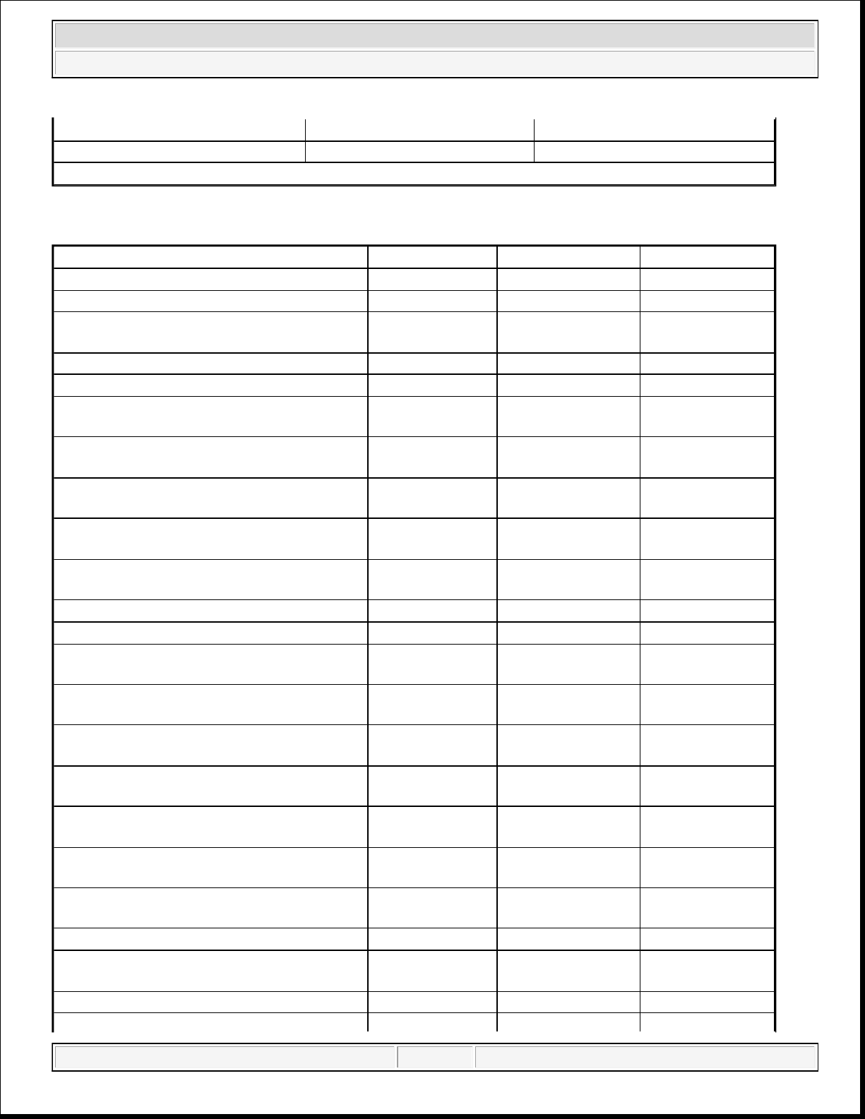
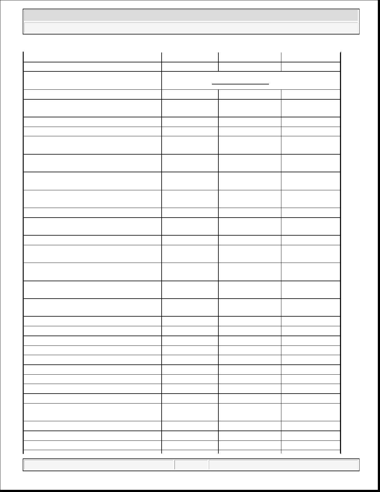
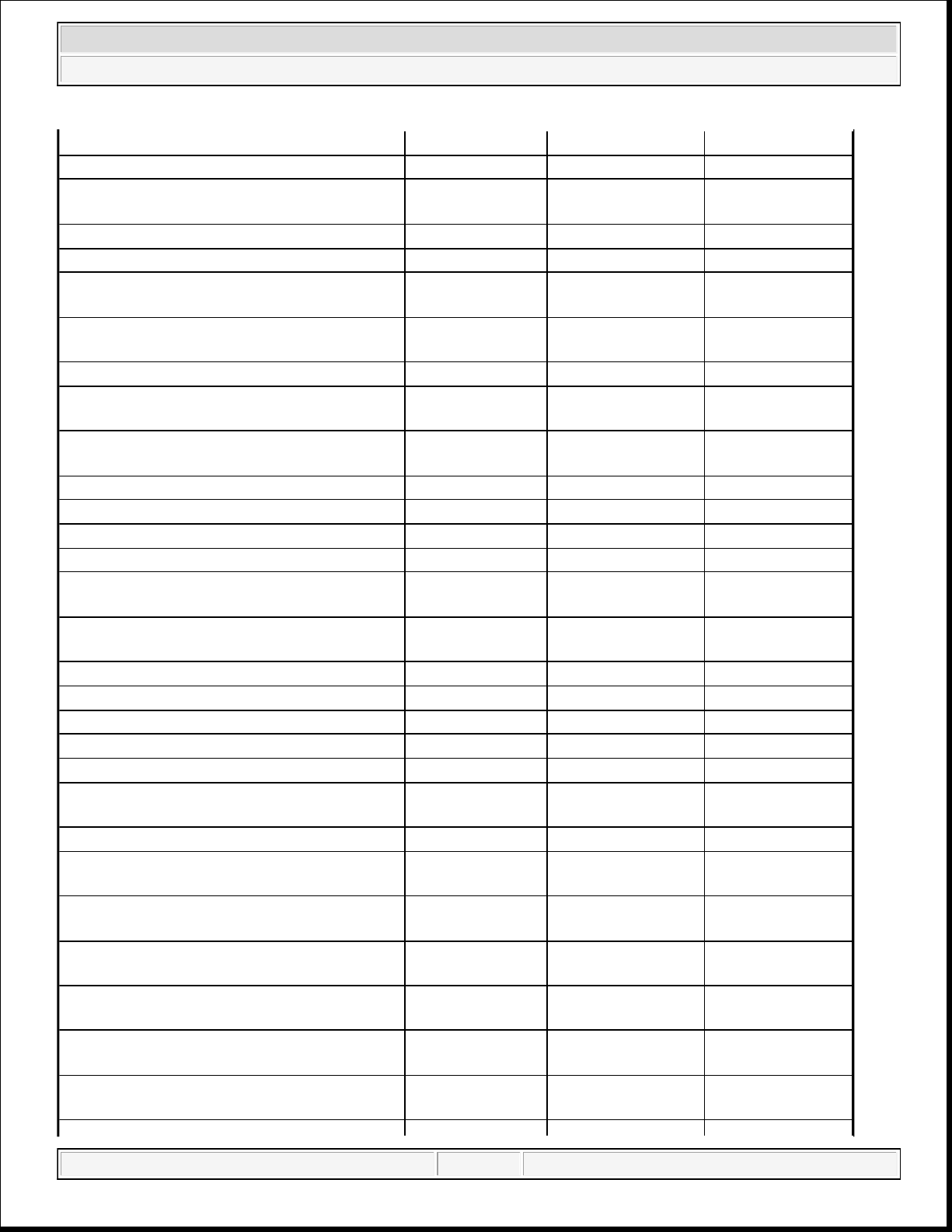
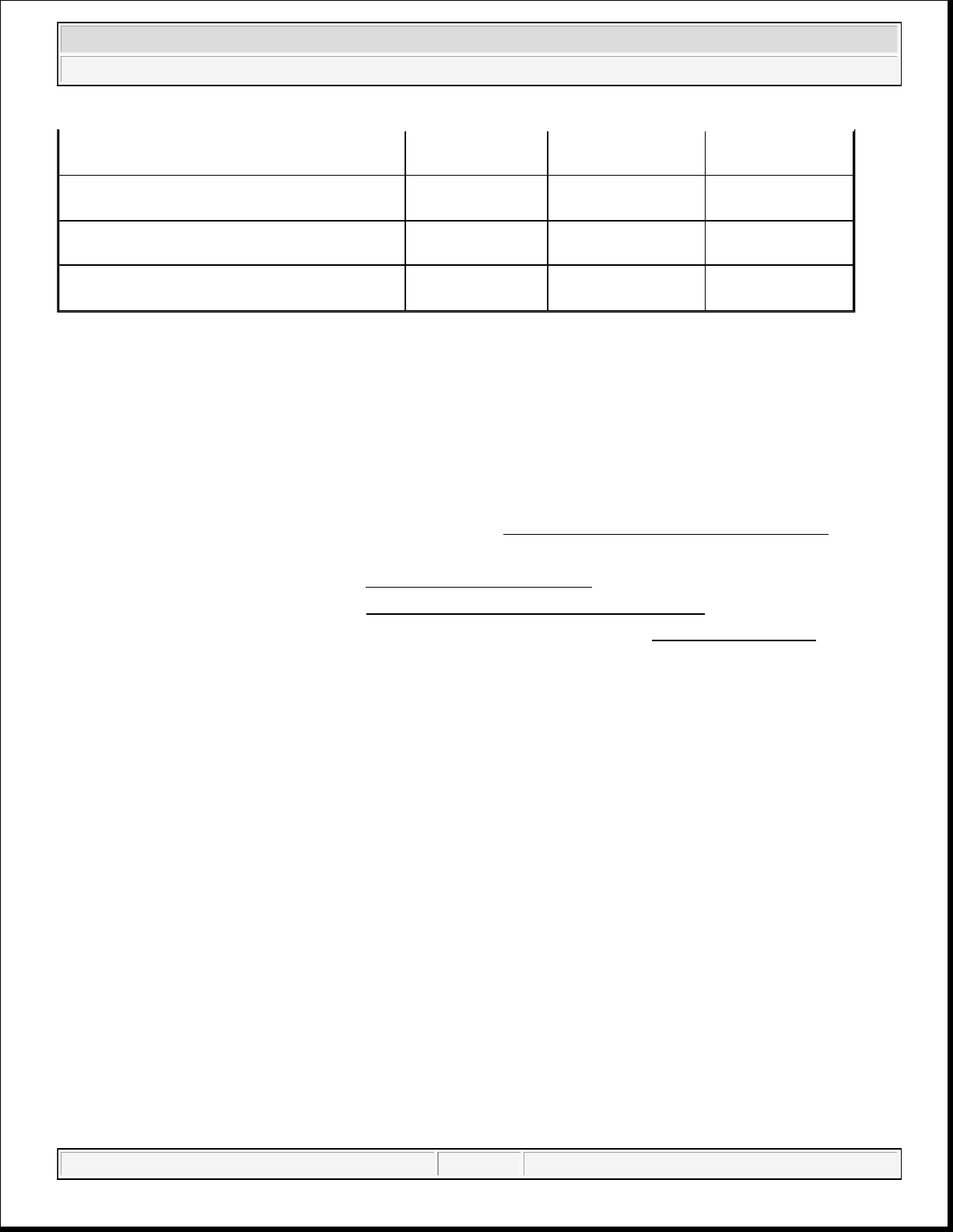
TORQUE SPECIFICATIONS
DESCRIPTION N.m Ft. Lbs. In. Lbs.
Air Inlet Hose - Band Clamps 4 - 35
A/C Compressor to Engine - M8 Bolts 25 18 Camshaft Chain Tensioner (Primary) - M6
T30
12 - 106
Camshaft Chain Guide (Primary) - M6 T30 12 - 106
Camshaft Chain Idler Sprocket - M8 T45 25 18 Camshaft Chain LH Tensioner (Secondary) -
12 - 106
M6 T30
Camshaft Chain LH Guide (Secondary) - M6
T30
Camshaft Chain RH Tensioner (Secondary) -
M6 T30
Camshaft Chain RH Guide (Secondary) - M6
T30
Camshaft Position (CMP) Sensor to Cylinder
Head - 6M T30
12 - 106
12 - 106
12 - 106
9 - 80
Camshaft Bearing Cap - M6 T30 9.5 - 84
Connecting Rod Cap - M9 Bolts 20 + 90° Turn 15 + 90° Turn Coolant Pump to Engine Timing Cover - M6
Bolts
Coolant Crossover Housing to Engine
Timing Cover - M6 Bolts
Coolant Pump to Engine Timing Cover -
M10 Bolt
Crankshaft Target Wheel to Counterweight -
12 - 106
12 - 106
55 40 -
10 - 89
M6 T30
Crankshaft Outer Main Bearing Cap and
21 + 90° Turn 16 + 90° Turn -
Windage Tray - M8 Bolts
Crankshaft Inner Main Bearing Cap - M11
20 + 90° Turn 15 + 90° Turn -
Bolts
Crankshaft Side Main Bearing Cap (Tie Bolt)
- M8 Bolts
28 - 250
Crankshaft Vibration Damper - M16 Bolt 40 + 105° Turn 30 + 105° Turn Crankshaft Position (CKP) Sensor to Engine
Block - M6 Bolt
12 - 106
Crankshaft Rear Oil Seal Retainer - M6 T30 12 - 106
domingo, 10 de octubre de 2021 04:48:06 p. m. Page 21 © 2011 Mitchell Repair Information Company, LLC.
Page 22
2014 RAM 1500 Laramie
2014 ENGINE 3.6L - Service Information - Ram Pickup
Cylinder Head Oil Galley Plug 18 9 Cylinder Head Oil Restrictor - M8 Plug 15 - 133
Cylinder Head to Engine Block - M12 Bolts
in Sequence
See INSTALLATION Procedure.
Cylinder Head Cover - M6 Bolts 12 - 106
Catalytic Converter to Cylinder Head - M8
23 17 -
Bolts
Engine Coolant Temperature (ECT) Sensor 11 - 97
Engine Block Heater - M6 Bolt 12 - 106
Left/Right Engine Mount Bracket to Engine
61 45 -
Block - M10 Bolts
Left/Right Engine Mount Isolator to Engine
Mount Bracket - M10 Nuts
Left/Right Engine Mount Heat shield to
Engine Mount Bracket - M6 Bolts
Left/Right Engine Mount Isolator to Frame -
M10 Bolts
61 45 -
12 - 106
61 45 -
Flexplate to Crankshaft - M10 Bolts 95 70 Fuel Rail to Lower Intake Manifold - M6
Bolts
7 - 62
Generator - M8 Bolts 25 18 Heater Core Supply Tube to Cylinder Head -
M8 Bolt
Idler Pulley to Engine Timing Cover -
Accessory Drive M8 Bolt
Ignition Capacitor to Cylinder Head - M6
Bolts
Ignition Coil to Cylinder Head Cover - M6
Bolts
12 - 106
25 18 -
10 - 89
8 - 71
Intake Manifold (Upper) - M6 Bolts 10 - 89
Intake Manifold (Lower) - M6 Bolts 12 - 106
Knock Sensor to Engine Block - M8 T40 22 16 Negative Battery Cable to Battery 5 - 45
Oil Control Valve - Cam Phaser M18 150 111 Upper Oil Pan to Engine Block - M8 Bolts 25 18 Transmission to Upper Oil Pan - M10 Bolts 55 41 Torque Converter Dust Shield - M8 Bolt 12 - 106
Oil Cooler to Oil Filter Housing Screws 4 - 35
Upper Oil Pan to Rear Seal Retainer - M6
10 - 89
Bolts
Oil Pan Drain - Plug M14 27 20 Oil Pressure Sensor to Oil Filter Housing 20 - 177
Oil Temperature Sensor to Oil Filter Housing 20 - 177
domingo, 10 de octubre de 2021 04:48:06 p. m. Page 22 © 2011 Mitchell Repair Information Company, LLC.
Page 23
2014 RAM 1500 Laramie
2014 ENGINE 3.6L - Service Information - Ram Pickup
Lower Oil Pan to Upper Oil Pan - M6 Bolts 10.5 - 93
Piston Oil Cooler Jet to Engine Block - M5 6 - 53
Oil Filter Housing/Oil Cooler to Engine
12 - 106
Block - M6 Bolts
Oil Filter Housing Cap 25 18 Oil Pump to Block - M6 Bolts 12 - 106
Oil Level Indicator to Engine Block - M10
Bolt
Oil Level Indicator to Cylinder Head - M6
35 26 -
12 - 106
Bolt
Oil Pump Sprocket - M8 T45 25 18 Oil Pump Pick Up Tube Bracket to Windage
12 - 106
Tray - M6 Bolt
Oil Pump Pick Up Tube to Oil Pump - M6
Bolt
12 - 106
Oxygen Sensor to Exhaust Pipe - M18 50 37 PCV Valve - M5 T25 4 - 35
Spark Plug to Cylinder Head - M12 17.5 13 Starter Mounting - M10 Bolts 54 40 Tensioner to Engine Timing Cover -
Accessory Drive M10 Bolt
Thermostat Housing to Coolant Crossover -
55 41 -
12 - 106
M6 Bolts
Throttle Body - M6 Bolts 7 - 62
Engine Timing Cover - M6 Bolts 12 - 106
Engine Timing Cover - M8 Bolt 25 18 Engine Timing Cover - M10 Bolts 55 41 Transmission to Engine Block - M10 Bolts 55 41 Transmission Fluid Indicator to Transmission
- M6 Bolt
12 - 106
Torque Converter - M8 Bolts 42 31 Upper Intake Manifold Support Bracket to
Cylinder Head - M8 Bolt
Upper Intake Manifold Support Bracket to
Upper Intake Manifold - M6 Nuts
Variable Valve Timing Solenoid to Cylinder
Head Cover - M5 T25
Wire Harness Retainer Bracket to LH
Cylinder Head - M6 T30
Rear Engine Mount Bracket to Transmission
- M8 Bolts
Rear Engine Mount Isolator to Rear Engine
Mount Bracket - M10 Bolts
20 - 177
10 - 89
4 - 35
12 - 106
33 24 -
61 45 -
domingo, 10 de octubre de 2021 04:48:06 p. m. Page 23 © 2011 Mitchell Repair Information Company, LLC.
Page 24
2014 RAM 1500 Laramie
2014 ENGINE 3.6L - Service Information - Ram Pickup
Rear Engine Mount Crossmember to Frame M10 Bolts
Rear Engine Mount Isolator to Crossmember
- M10 Bolts
Left/Right Crossmember Brace to
Crossmember - M8 Bolts
Left/Right Crossmember Brace to Frame -
M8 Bolts
55 41 -
61 45 -
55 41 -
55 41 -
REMOVAL
REMOVAL
CAUTION: If the original engine has experienced a catastrophic failure or an
individual failure with the piston, cylinder bore, engine block, valve or
valve seat, the intake manifold MUST be replaced with a new manifold.
1. Perform the fuel pressure release procedure. Refer to FUEL SYSTEM PRESSURE RELEASE .
2. Disconnect and isolate the battery negative cable.
3. Drain the cooling system. Refer to STANDARD PROCEDURE .
4. Evacuate the A/C system. Refer to PLUMBING, STANDARD PROCEDURE .
5. With the help of an assistant, remove the hood from the vehicle. Refer to HOOD, REMOVAL .
NOTE: The engine cover is bonded to the air intake assembly. Do not attempt to
separate them. The cover and intake must be removed as an assembly.
domingo, 10 de octubre de 2021 04:48:06 p. m. Page 24 © 2011 Mitchell Repair Information Company, LLC.
Page 25
2014 RAM 1500 Laramie
2014 ENGINE 3.6L - Service Information - Ram Pickup
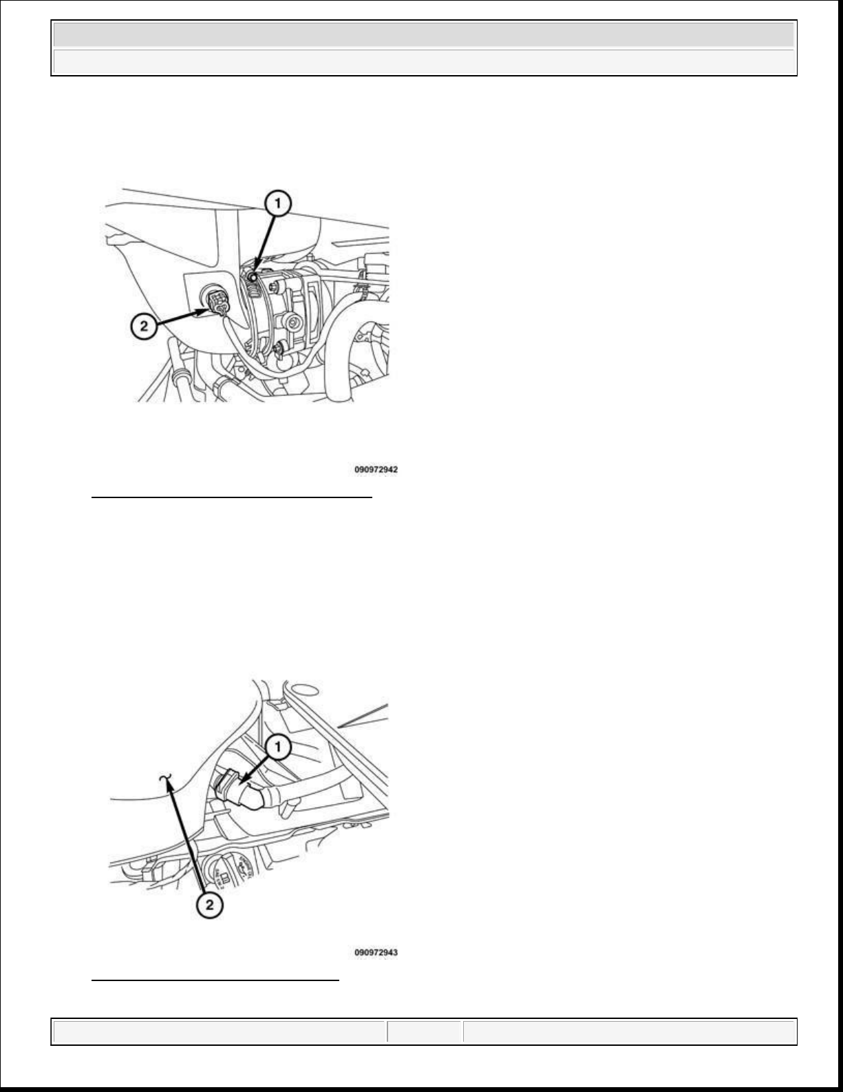
Fig. 5: IAT Sensor Electrical Connector
Courtesy of CHRYSLER GROUP, LLC
6. Loosen the air intake clamp (1) at the throttle body.
7. Disconnect the Intake Air Temperature (IAT) sensor (2).
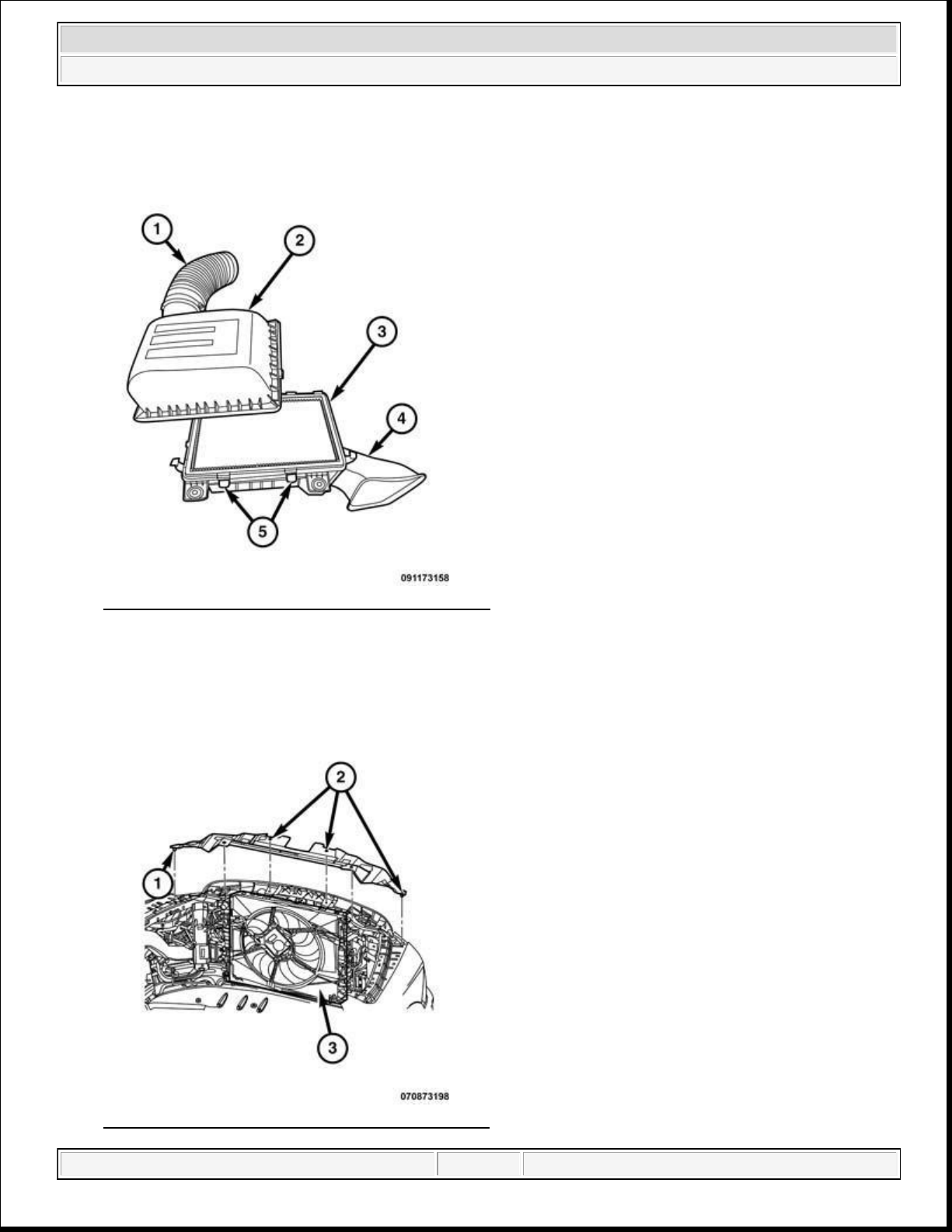
Fig. 6: Breather Tube & Resonator
Courtesy of CHRYSLER GROUP, LLC
domingo, 10 de octubre de 2021 04:48:06 p. m. Page 25 © 2011 Mitchell Repair Information Company, LLC.
Page 26
2014 RAM 1500 Laramie
2014 ENGINE 3.6L - Service Information - Ram Pickup
8. Remove the breather tube (1) from the resonator (2).
Fig. 7: Removing/Installing Air Filter Box Cover
Courtesy of CHRYSLER GROUP, LLC
9. Remove the air filter housing cover (2) and lower housing assembly (4).
Fig. 8: Removing/Installing Electric Cooling Fan
domingo, 10 de octubre de 2021 04:48:06 p. m. Page 26 © 2011 Mitchell Repair Information Company, LLC.
Page 27
Courtesy of CHRYSLER GROUP, LLC
12.
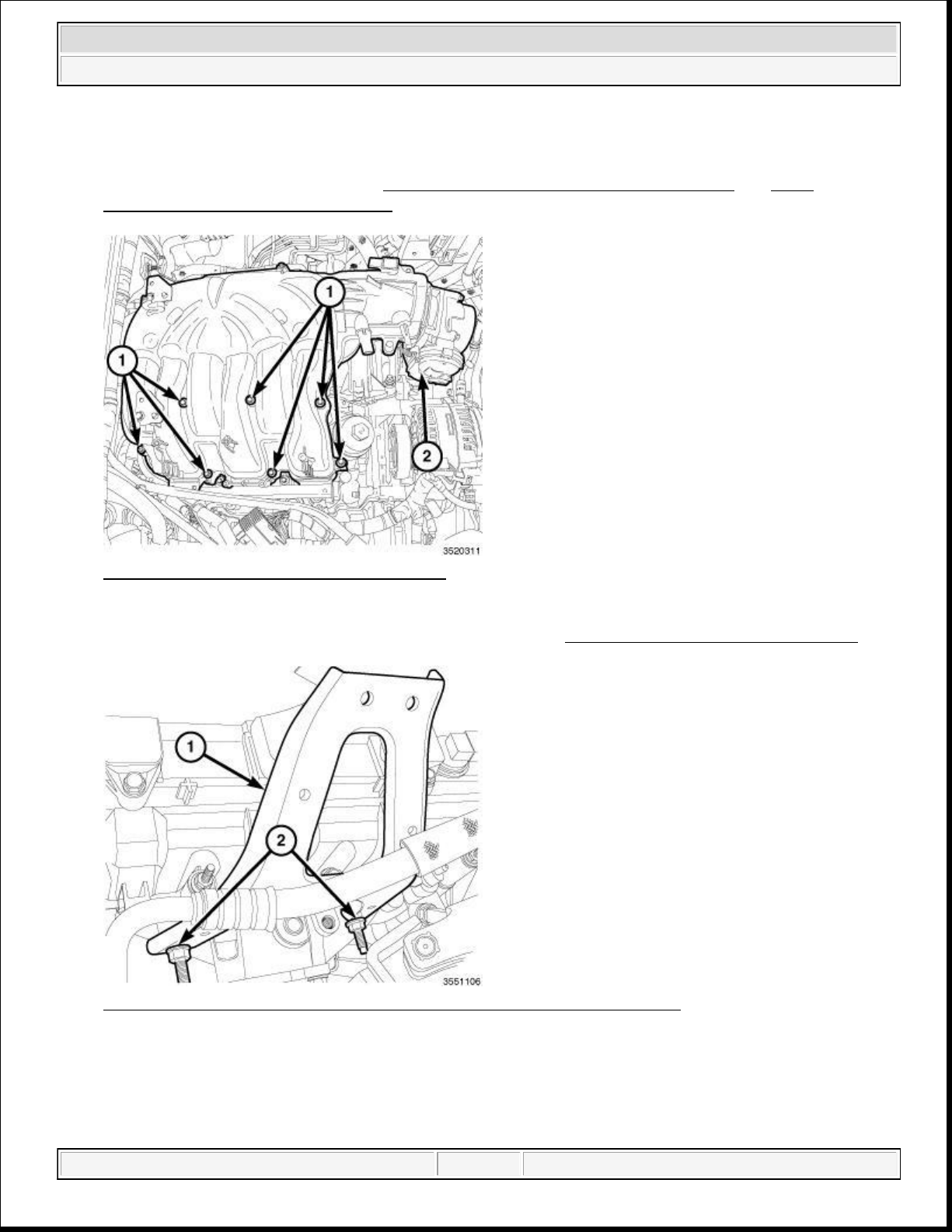
Remove the two stud bolts (2) and remove the left rear upper intake manifold support bracket (1).
2014 RAM 1500 Laramie
2014 ENGINE 3.6L - Service Information - Ram Pickup
10. Remove the cooling fan (3). Refer to FAN, COOLING, ELECTRIC, REMOVAL and FAN,
COOLING, VISCOUS, REMOVAL .
Fig. 9: Upper Intake Manifold & Fasteners
Courtesy of CHRYSLER GROUP, LLC
11. Remove the upper intake manifold (2) and insulator. Refer to MANIFOLD, INTAKE, REMOVAL .
Fig. 10: Left Rear Upper Intake Manifold Support Bracket & Stud Bolts
Courtesy of CHRYSLER GROUP, LLC
domingo, 10 de octubre de 2021 04:48:07 p. m. Page 27 © 2011 Mitchell Repair Information Company, LLC.
Page 28
PROCEDURE
.
2014 RAM 1500 Laramie
2014 ENGINE 3.6L - Service Information - Ram Pickup
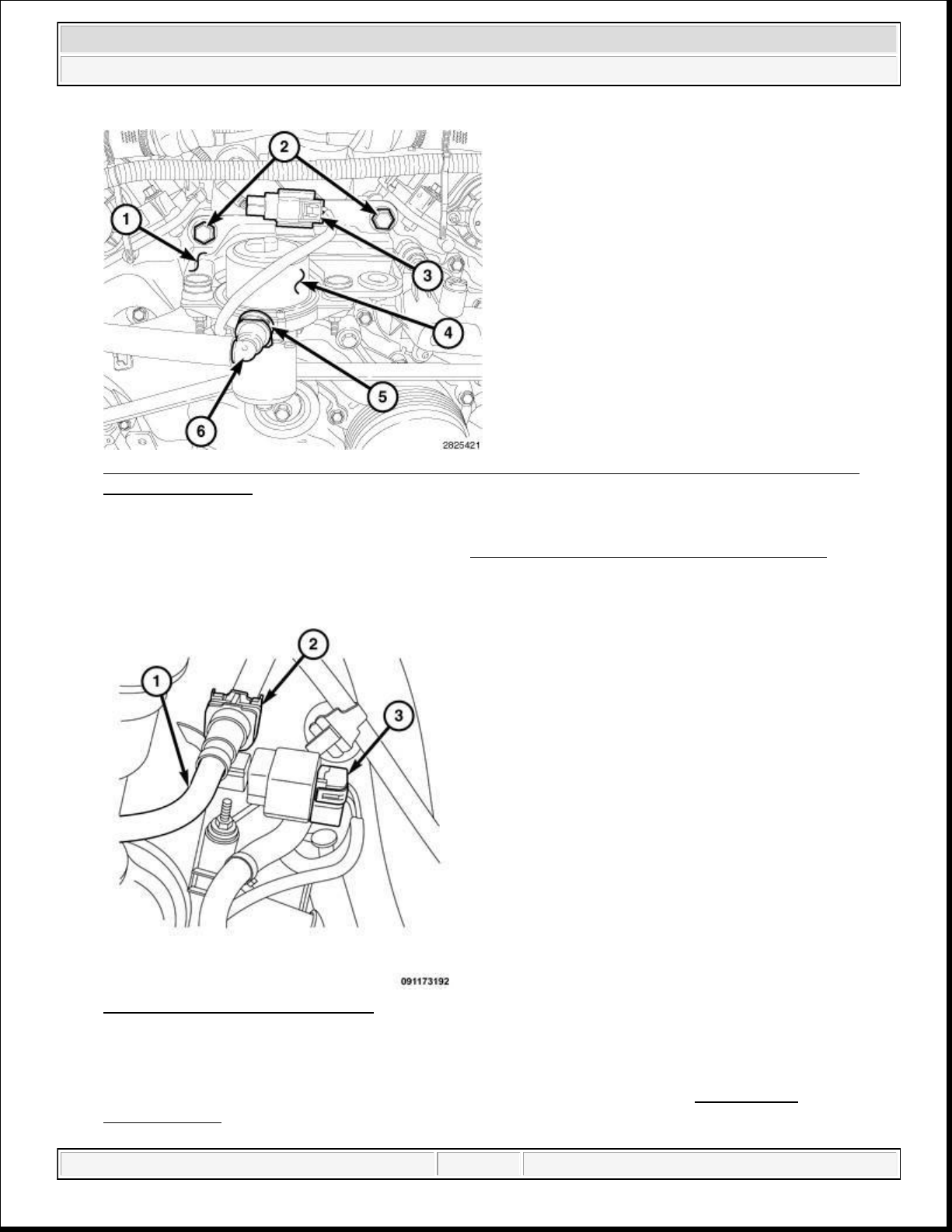
Fig. 11: Mounting Bracket, Bolts, Electrical Connector, Vacuum Pump, Locking Tab & QuickConnect Type End
Courtesy of CHRYSLER GROUP, LLC
13. Remove the vacuum pump and bracket. Refer to PUMP, ELECTRIC VACUUM, REMOVAL .
Fig. 12: Fuel Rail Pressure Sensor
Courtesy of CHRYSLER GROUP, LLC
14. Disconnect the fuel pressure sensor electrical connector (3).
15. Disconnect the fuel supply hose (2) at the in-line fuel pressure sensor. Refer to STANDARD
domingo, 10 de octubre de 2021 04:48:07 p. m. Page 28 © 2011 Mitchell Repair Information Company, LLC.
Page 29
2014 RAM 1500 Laramie
2014 ENGINE 3.6L - Service Information - Ram Pickup
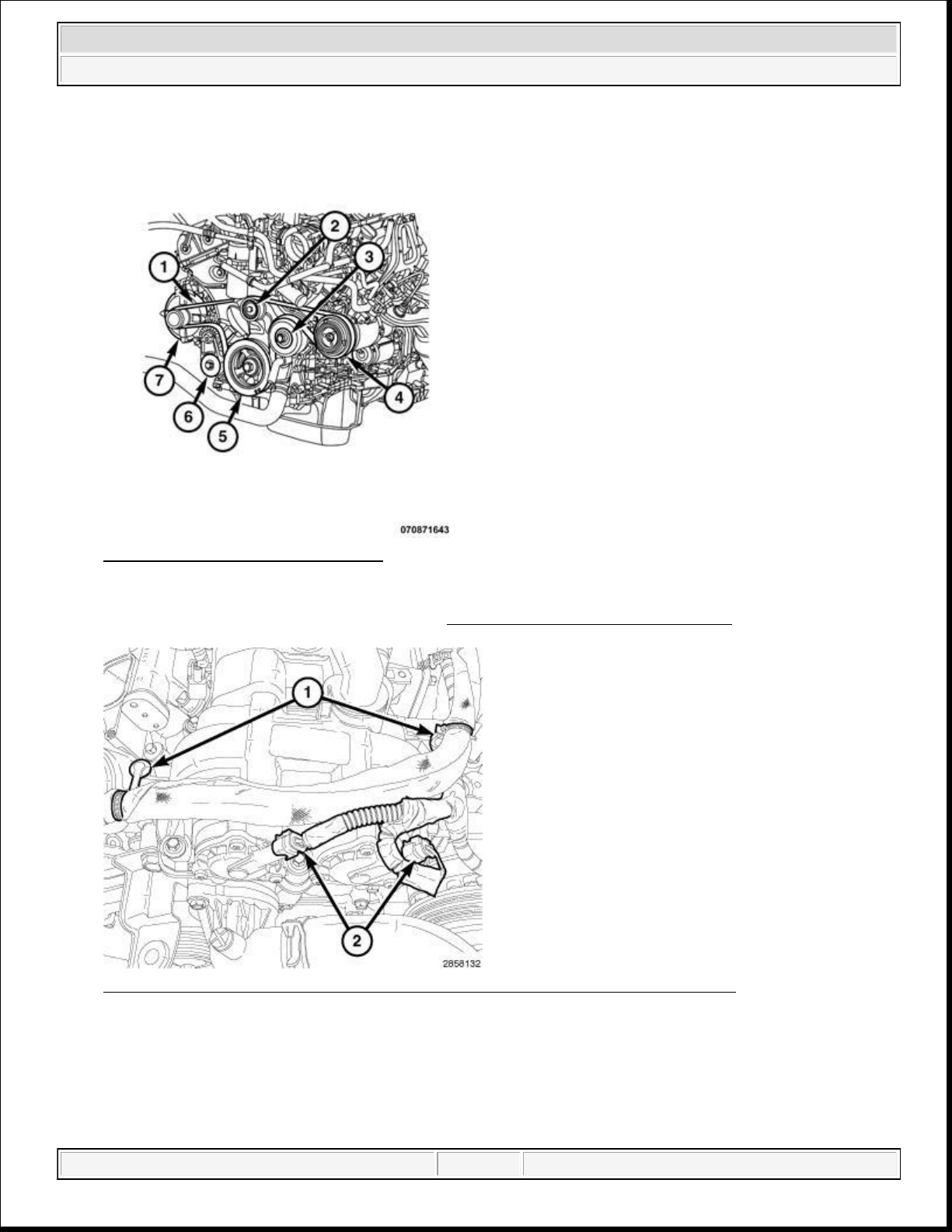
Fig. 13: Belt Routing (3.6L Engine)
Courtesy of CHRYSLER GROUP, LLC
16. Remove the accessory drive belt (1). Refer to BELT, SERPENTINE, REMOVAL .
Fig. 14: Variable Valve Timing Solenoid Connectors & Wire Harness Retainers
Courtesy of CHRYSLER GROUP, LLC
NOTE: Mark and disconnect the left bank variable valve timing solenoid
connectors (2) with a paint pen or equivalent so that they may be
reinstalled in their original locations.
domingo, 10 de octubre de 2021 04:48:07 p. m. Page 29 © 2011 Mitchell Repair Information Company, LLC.
Page 30
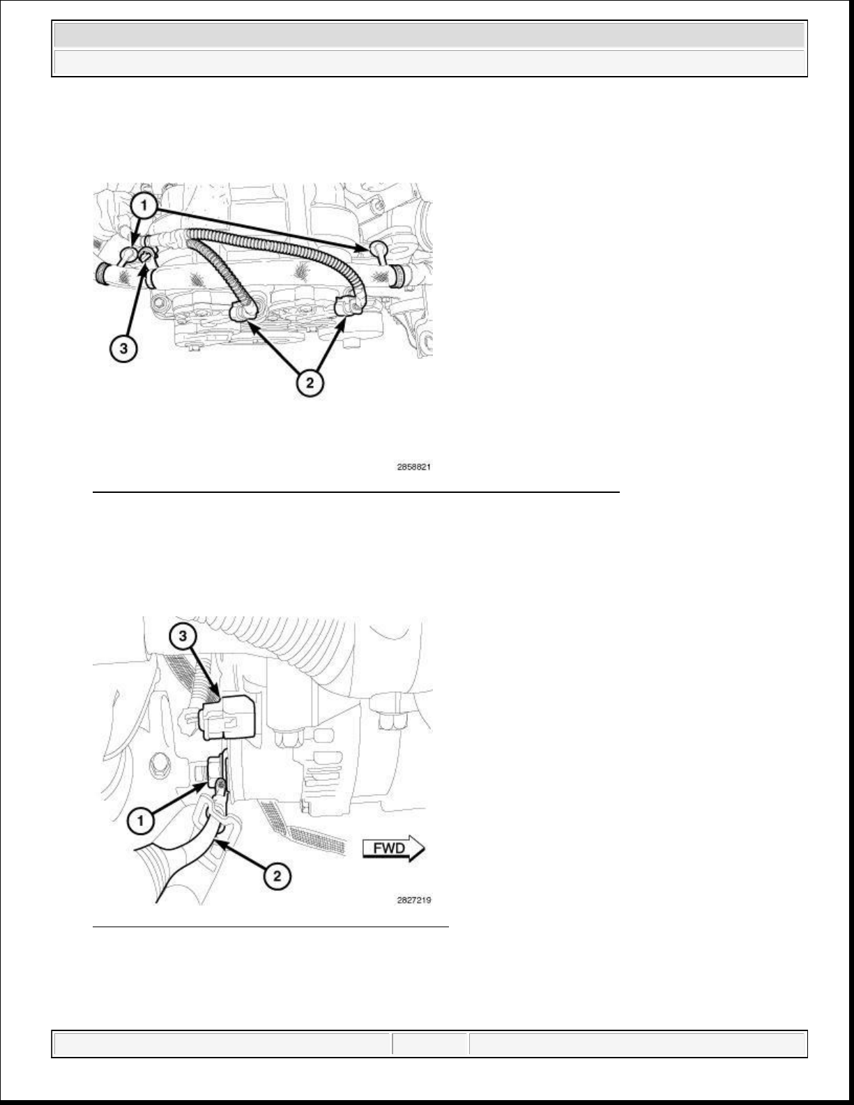
23.
Remove the B+ terminal cable (2) from the generator stud.
2014 RAM 1500 Laramie
2014 ENGINE 3.6L - Service Information - Ram Pickup
17. Remove the wire harness retainers (1) from the left cylinder head cover.
18. Disconnect the left side upstream O2 sensor wiring harness connector.
Fig. 15: Variable Valve Timing Solenoid Connectors & Harness Retainers
Courtesy of CHRYSLER GROUP, LLC
19. Mark and disconnect the right intake variable valve timing solenoid electrical connector (6).
20. Remove the wire harness retainers (1 and 3) from the right cylinder head cover.
21. Disconnect the right side upstream O2 sensor wiring harness connector.
Fig. 16: Field Circuit, B+ Terminal Nut And Wire
Courtesy of CHRYSLER GROUP, LLC
22. Disconnect the field circuit connector (3) from the generator.
domingo, 10 de octubre de 2021 04:48:07 p. m. Page 30 © 2011 Mitchell Repair Information Company, LLC.
Page 31
2014 RAM 1500 Laramie
2014 ENGINE 3.6L - Service Information - Ram Pickup
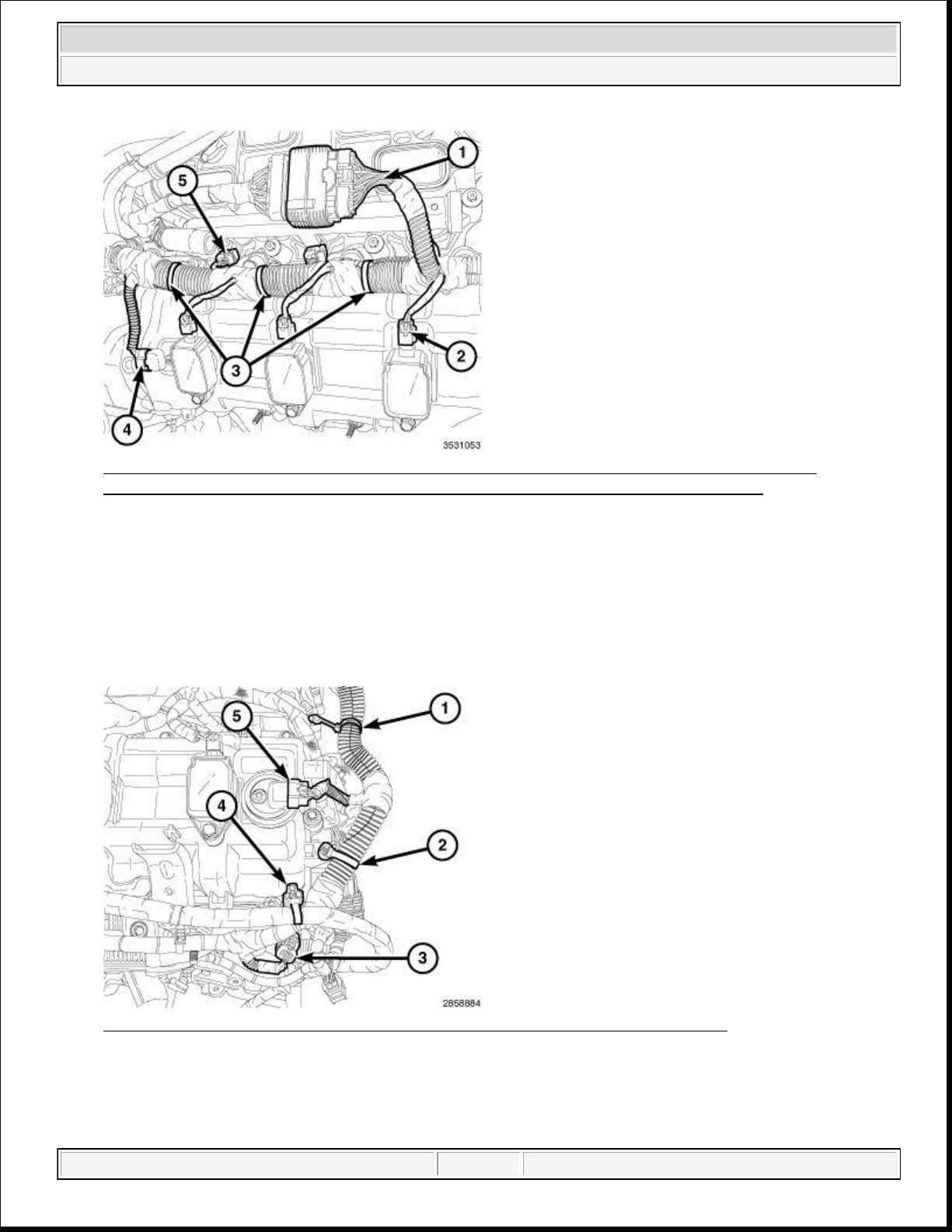
Fig. 17: Engine Injection/Ignition Harness, Ignition Coil Electrical Connectors, Retainers,
Camshaft Position (CMP) Sensor Connector & Fuel Injector Electrical Connectors
Courtesy of CHRYSLER GROUP, LLC
24. Disconnect the main harness from the engine injection/ignition harness (1).
25. Disconnect three fuel injector electrical connectors (5).
26. Disconnect three ignition coil electrical connectors (2).
27. Disconnect the electrical connector (4) from the right Camshaft Position (CMP) sensor.
28. Remove the three main wire harness retainers (3) from the right cylinder head cover.
Fig. 18: ECT Sensor Connector, CMP Sensor & Main Wire Harness Retainers
Courtesy of CHRYSLER GROUP, LLC
29. Disconnect the left Camshaft Position (CMP) sensor (5).
30. Remove the wire harness retainers (1, 2, and 4) from the cylinder head cover mounting stud.
domingo, 10 de octubre de 2021 04:48:07 p. m. Page 31 © 2011 Mitchell Repair Information Company, LLC.
Page 32
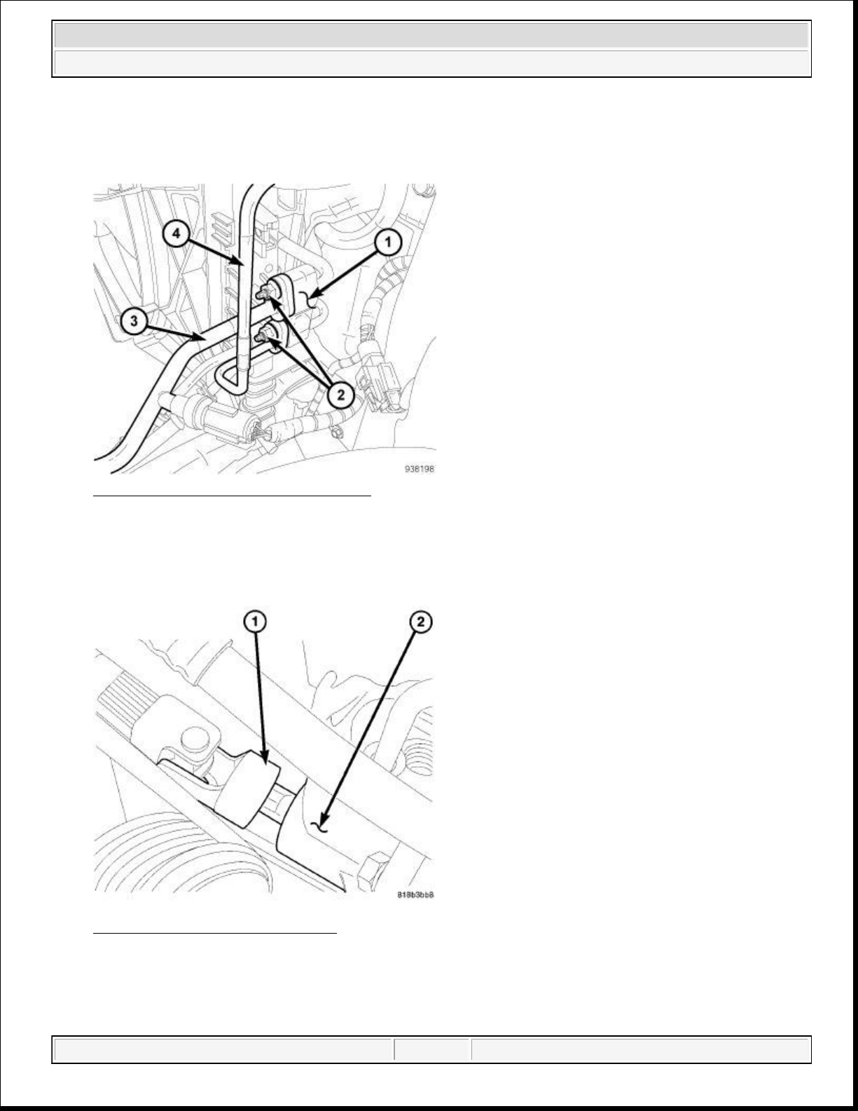
35.
Remove the lower intermediate shaft coupler (1) at the steering gear (2).
2014 RAM 1500 Laramie
2014 ENGINE 3.6L - Service Information - Ram Pickup
31. Remove the ground straps (1) from the back of the cylinder heads.
32. Disconnect the ignition coil capacitor electrical connectors (2).
Fig. 19: A/C Discharge & Liquid Lines
Courtesy of CHRYSLER GROUP, LLC
33. Disconnect the A/C compressor electrical connector.
34. Remove the A/C lines (2) at the condenser (1).
Fig. 20: Lower Coupling AT Gear
Courtesy of CHRYSLER GROUP, LLC
domingo, 10 de octubre de 2021 04:48:07 p. m. Page 32 © 2011 Mitchell Repair Information Company, LLC.
Page 33
2014 RAM 1500 Laramie
2014 ENGINE 3.6L - Service Information - Ram Pickup
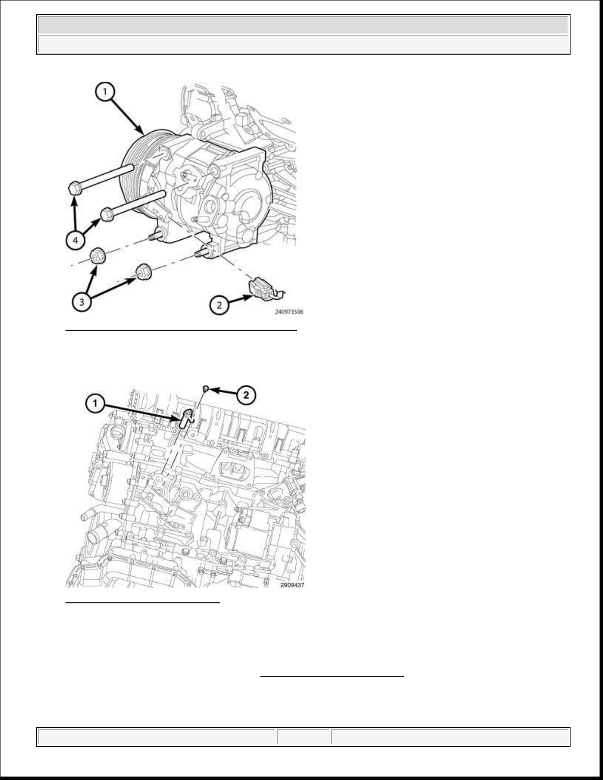
Fig. 21: Removing/Installing A/C Compressor
Courtesy of CHRYSLER GROUP, LLC
36. Remove the A/C compressor (2).
Fig. 22: Block Heater & Screw
Courtesy of CHRYSLER GROUP, LLC
37. Disconnect the power cord from the engine block heater (if equipped).
38. Partially raise the vehicle.
39. If required, drain the engine oil. Refer to STANDARD PROCEDURE.
NOTE: Right catalytic converter shown in illustration, left catalytic converter
domingo, 10 de octubre de 2021 04:48:07 p. m. Page 33 © 2011 Mitchell Repair Information Company, LLC.
Page 34
similar.
2014 RAM 1500 Laramie
2014 ENGINE 3.6L - Service Information - Ram Pickup
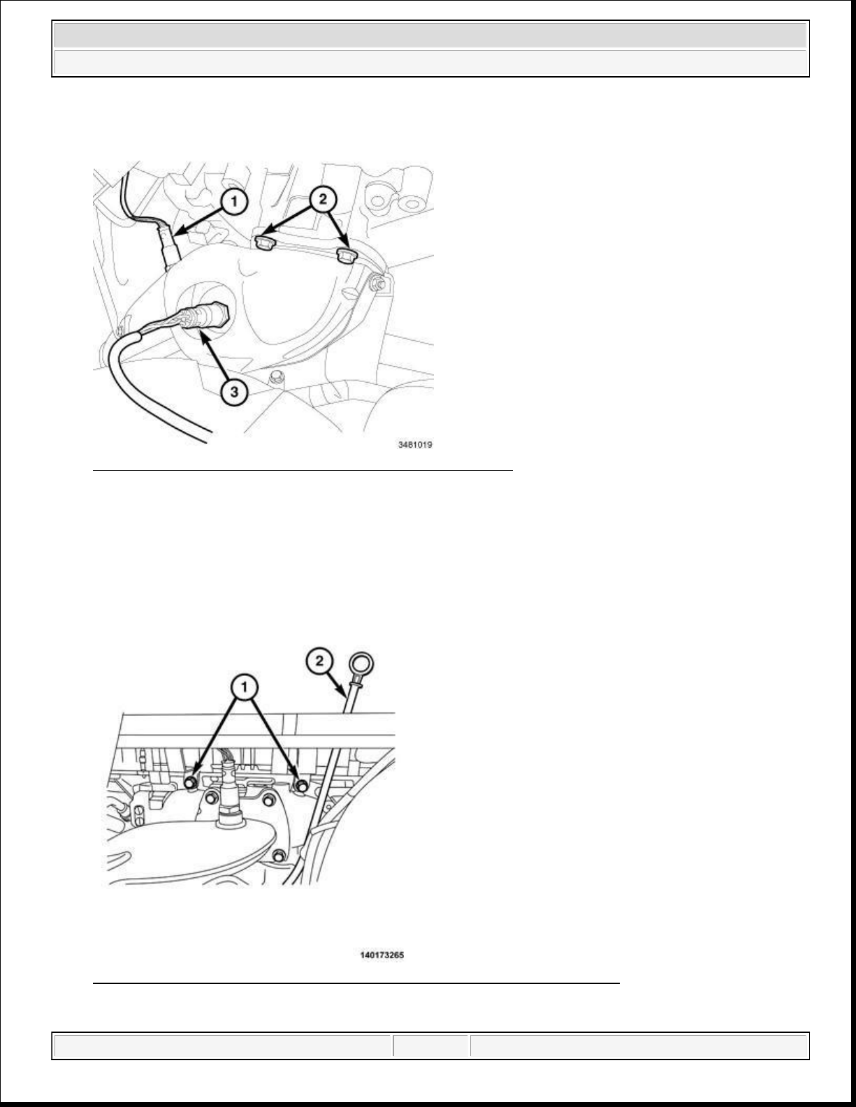
Fig. 23: Upstream & Downstream Oxygen Sensors & Bolts
Courtesy of CHRYSLER GROUP, LLC
40. Remove the front wheels.
41. Remove the right and left upper catalytic converter bolts (2).
42. Disconnect the right and left side downstream oxygen sensor (1) connectors from the main wire harness.
Fig. 24: Coolant Heater Tubes-To-Cylinder Head Bolts And Oil Indicator
Courtesy of CHRYSLER GROUP, LLC
domingo, 10 de octubre de 2021 04:48:07 p. m. Page 34 © 2011 Mitchell Repair Information Company, LLC.
Page 35
2014 RAM 1500 Laramie
2014 ENGINE 3.6L - Service Information - Ram Pickup
43. Remove the bolts (1) that secure the coolant heater tubes to the cylinder head.
44. Remove the oil indicator (2).
45. Raise the vehicle.
NOTE: Right side catalytic converter flange shown in illustration. Left side similar.
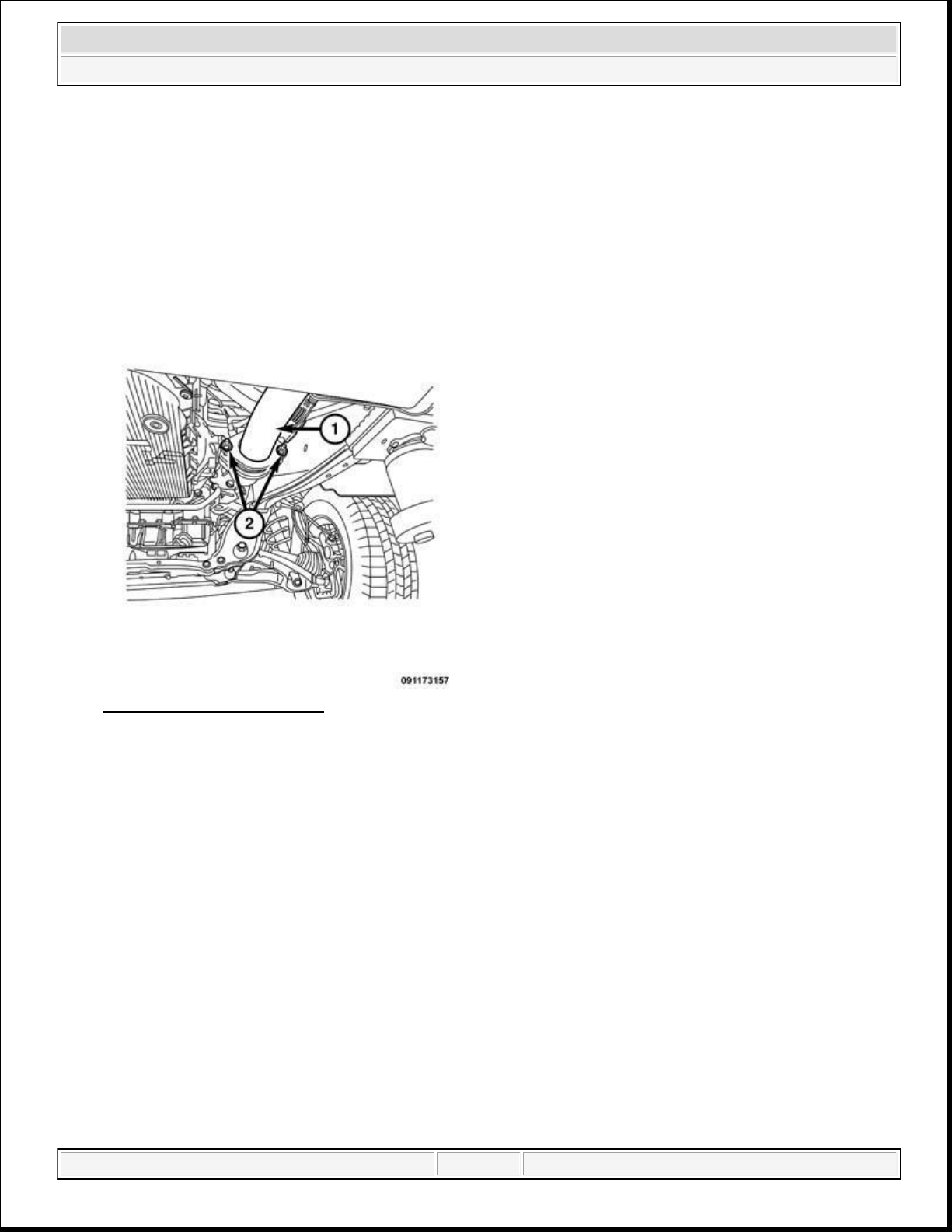
Fig. 25: Y-Pipe Flange Nuts
Courtesy of CHRYSLER GROUP, LLC
46. Remove the left and right side catalytic converter to Y-pipe (1) flange nuts (2).
47. Remove the catalytic converters from the vehicle.
48. Loosen the catalytic converter flange bolts.
domingo, 10 de octubre de 2021 04:48:07 p. m. Page 35 © 2011 Mitchell Repair Information Company, LLC.
Page 36
2014 RAM 1500 Laramie
2014 ENGINE 3.6L - Service Information - Ram Pickup
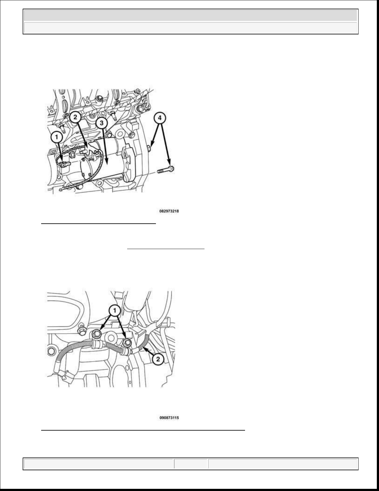
Fig. 26: Removing/Installing Starter
Courtesy of CHRYSLER GROUP, LLC
49. Remove the starter. Refer to STARTER, REMOVAL .
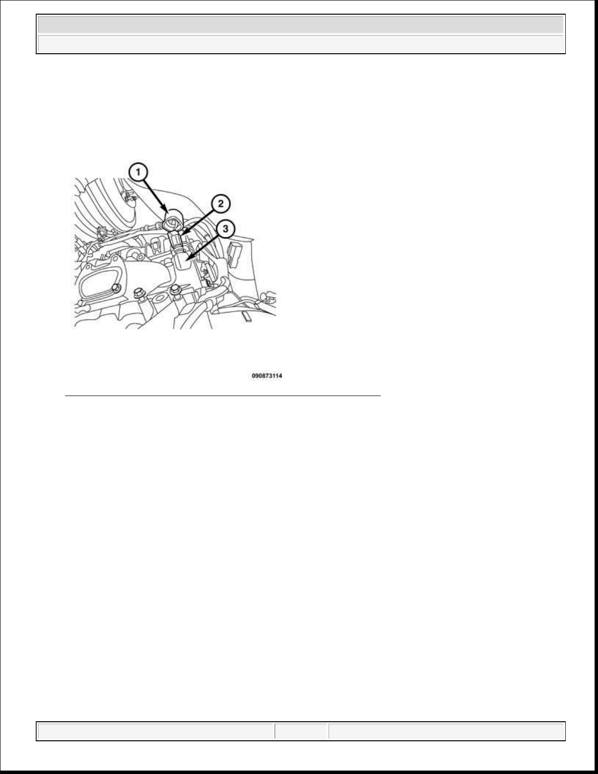
Fig. 27: Starter Solenoid Wiring Harness-To-Engine Block Bolts
Courtesy of CHRYSLER GROUP, LLC
domingo, 10 de octubre de 2021 04:48:07 p. m. Page 36 © 2011 Mitchell Repair Information Company, LLC.
Page 37
2014 RAM 1500 Laramie
2014 ENGINE 3.6L - Service Information - Ram Pickup
50. Remove the bolts (1) that secures the starter solenoid wiring harness (2) to the engine block, and position
aside.
Fig. 28: Identifying Engine Coolant Temperature Sensor (3.6L)
Courtesy of CHRYSLER GROUP, LLC
51. Slide the heat shield cover (1) from the temperature sensor (2).
52. Disconnect the Engine Coolant Temperature (ECT) sensor connector.
domingo, 10 de octubre de 2021 04:48:07 p. m. Page 37 © 2011 Mitchell Repair Information Company, LLC.
Page 38
2014 RAM 1500 Laramie
2014 ENGINE 3.6L - Service Information - Ram Pickup
Fig. 29: Removing/Installing Battery Ground Cable
Courtesy of CHRYSLER GROUP, LLC
53. Remove the battery ground cable (1) from the engine block.
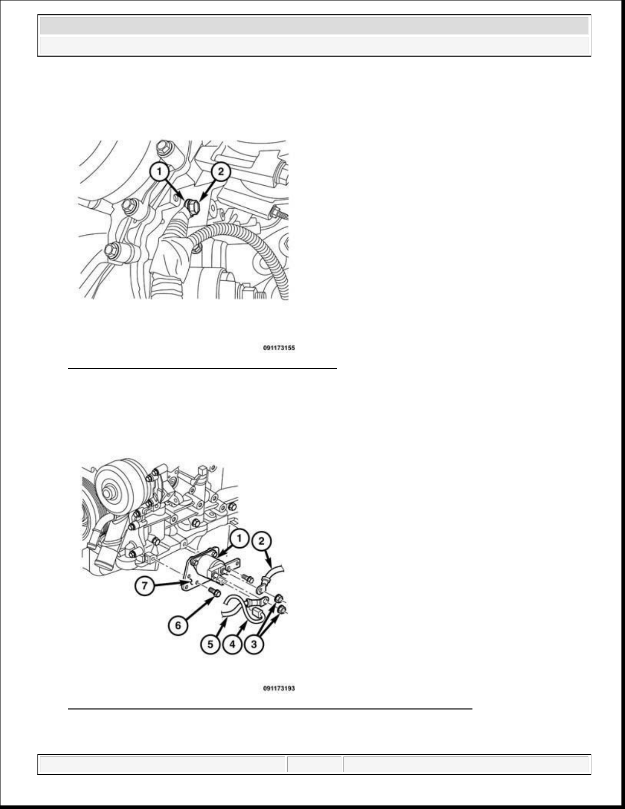
Fig. 30: Stop/Start Solenoid, Electrical Connector And Battery Positive Cable
Courtesy of CHRYSLER GROUP, LLC
domingo, 10 de octubre de 2021 04:48:07 p. m. Page 38 © 2011 Mitchell Repair Information Company, LLC.
Page 39
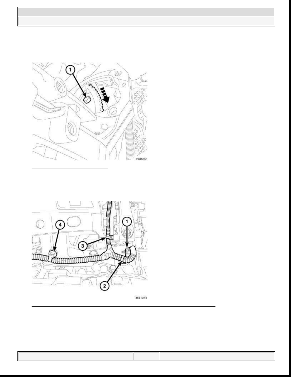
59.
Remove the wire harness retainer (2) from the engine block.
2014 RAM 1500 Laramie
2014 ENGINE 3.6L - Service Information - Ram Pickup
54. Disconnect the stop/start solenoid (1) electrical connector (4).
55. Remove the Battery positive cable (5) from the stop/start solenoid.
Fig. 31: Torque Converter Bolt
Courtesy of CHRYSLER GROUP, LLC
56. Rotate the crankshaft in a clockwise direction until the torque converter bolts (1) are accessible through
the starter mounting.
Fig. 32: Oil Pump Solenoid Electrical Connector & Wire Harness Retainers
Courtesy of CHRYSLER GROUP, LLC
57. Remove the main wire harness retainer (4) from the engine block.
58. Disconnect the oil pump solenoid electrical connector (1).
domingo, 10 de octubre de 2021 04:48:07 p. m. Page 39 © 2011 Mitchell Repair Information Company, LLC.
Page 40
2014 RAM 1500 Laramie
2014 ENGINE 3.6L - Service Information - Ram Pickup
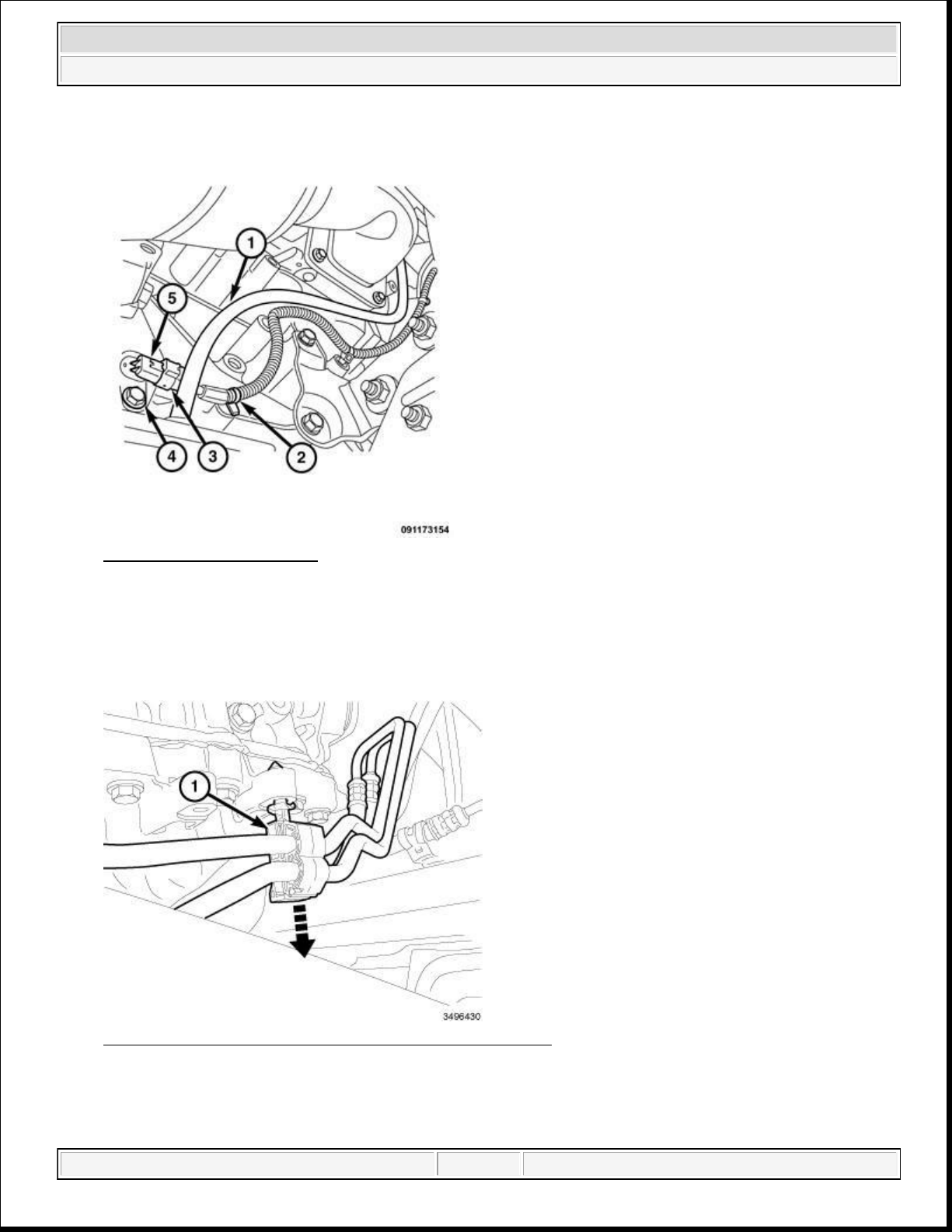
Fig. 33: CKP Sensor - 3.6L
Courtesy of CHRYSLER GROUP, LLC
60. Remove the wire harness retainer from the oil level indicator tube (1).
61. Remove the crankshaft positioning sensor electrical connector (3).
62. Remove the wire harness retainers from the engine block (2).
Fig. 34: Disengaging Transmission Cooler Line Retainer
Courtesy of CHRYSLER GROUP, LLC
63. Remove the transmission cooler line retainer (1) from the oil pan flange.
domingo, 10 de octubre de 2021 04:48:07 p. m. Page 40 © 2011 Mitchell Repair Information Company, LLC.
Page 41
2014 RAM 1500 Laramie
2014 ENGINE 3.6L - Service Information - Ram Pickup
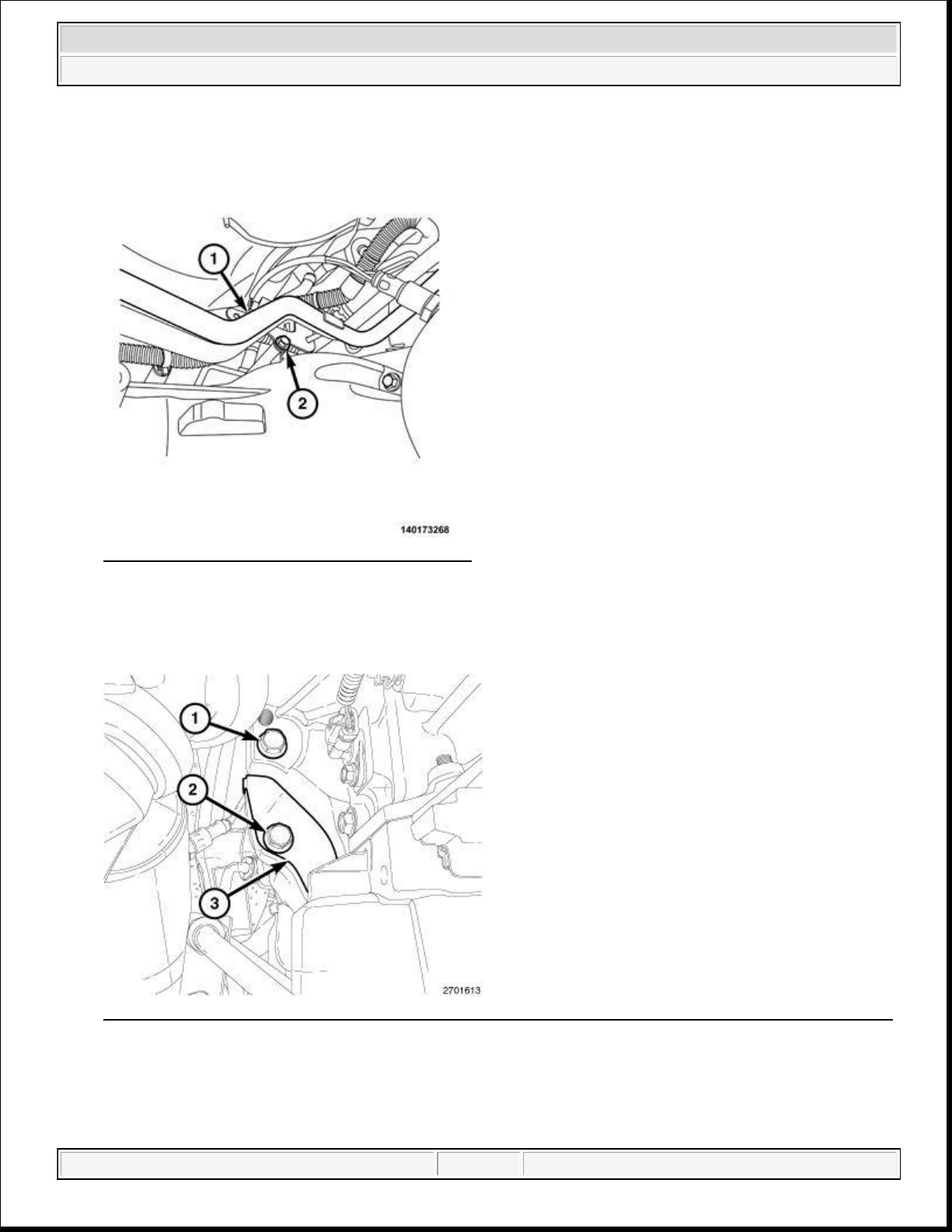
Fig. 35: Thermal Management Lines And Bolt
Courtesy of CHRYSLER GROUP, LLC
64. Remove the bolt (2) that secures the thermal management lines (1) to the transmission bell housing.
65. Remove the transmission heater hose from the thermal management line.
Fig. 36: Side Engine-To-Transmission Bolt, Transmission Dust Shield Retaining Bolt & Dust Shield
Courtesy of CHRYSLER GROUP, LLC
66. Remove the bolt (2) and the torque converter dust shield (3).
67. Remove the side engine to transmission bolt (1).
domingo, 10 de octubre de 2021 04:48:07 p. m. Page 41 © 2011 Mitchell Repair Information Company, LLC.
Page 42
2014 RAM 1500 Laramie
2014 ENGINE 3.6L - Service Information - Ram Pickup
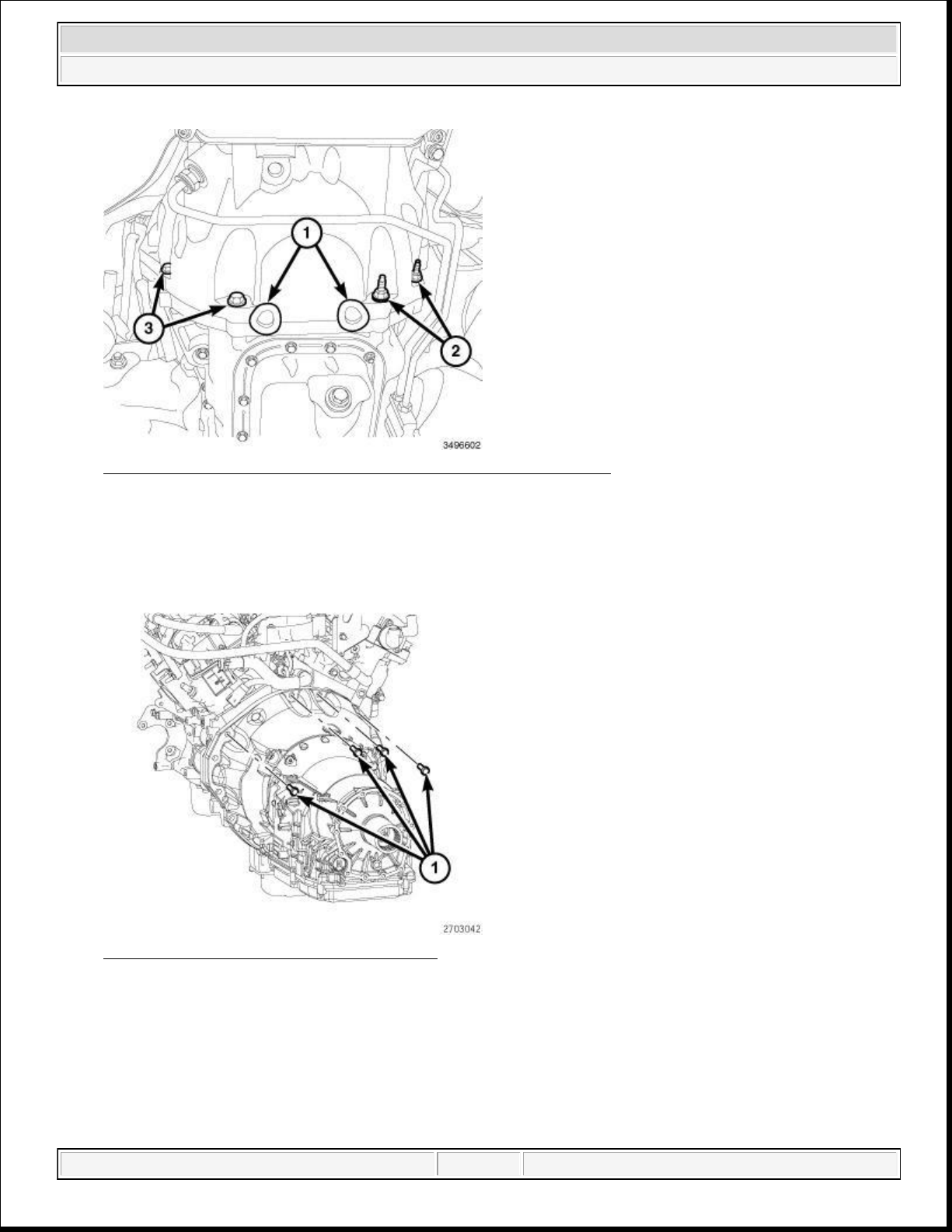
Fig. 37: Rubber Plugs & Transmission-To-Engine Oil Pan Bolts
Courtesy of CHRYSLER GROUP, LLC
68. If equipped with an automatic transmission;
Remove two rubber plugs (1) covering the rear oil seal retainer flange bolts.
Remove four transmission to the engine oil pan bolts (2 and 3).
Fig. 38: Upper Transmission Engine Bolts
Courtesy of CHRYSLER GROUP, LLC
69. Remove four upper transmission to engine bolts (1).
domingo, 10 de octubre de 2021 04:48:07 p. m. Page 42 © 2011 Mitchell Repair Information Company, LLC.
Page 43
Courtesy of CHRYSLER GROUP, LLC
2014 RAM 1500 Laramie
2014 ENGINE 3.6L - Service Information - Ram Pickup
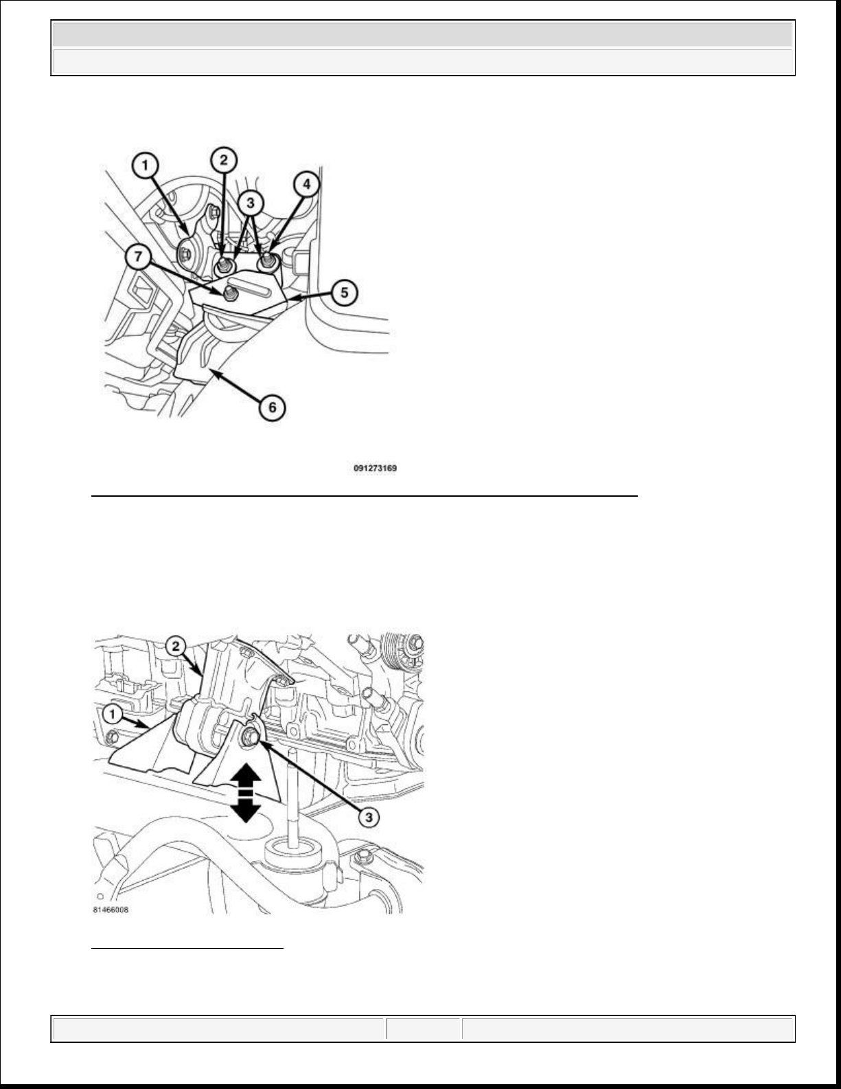
Fig. 39: Remove/Install Engine Mount, Heat Shield And Engine Bracket Bolts
Courtesy of CHRYSLER GROUP, LLC
70. Remove the engine mount (6) heat shield (5).
71. Loosen the outer engine bracket bolt (4) from the engine bracket.
72. Remove the inner through engine bracket bolt (2).
Fig. 40: Engine Mount Bolt
domingo, 10 de octubre de 2021 04:48:07 p. m. Page 43 © 2011 Mitchell Repair Information Company, LLC.
Page 44
73. 2WD vehicles,
76.
Remove the heater line at the coolant crossover (1).
Loosen the engine support bolt (3).
74. Lower the vehicle.
2014 RAM 1500 Laramie
2014 ENGINE 3.6L - Service Information - Ram Pickup
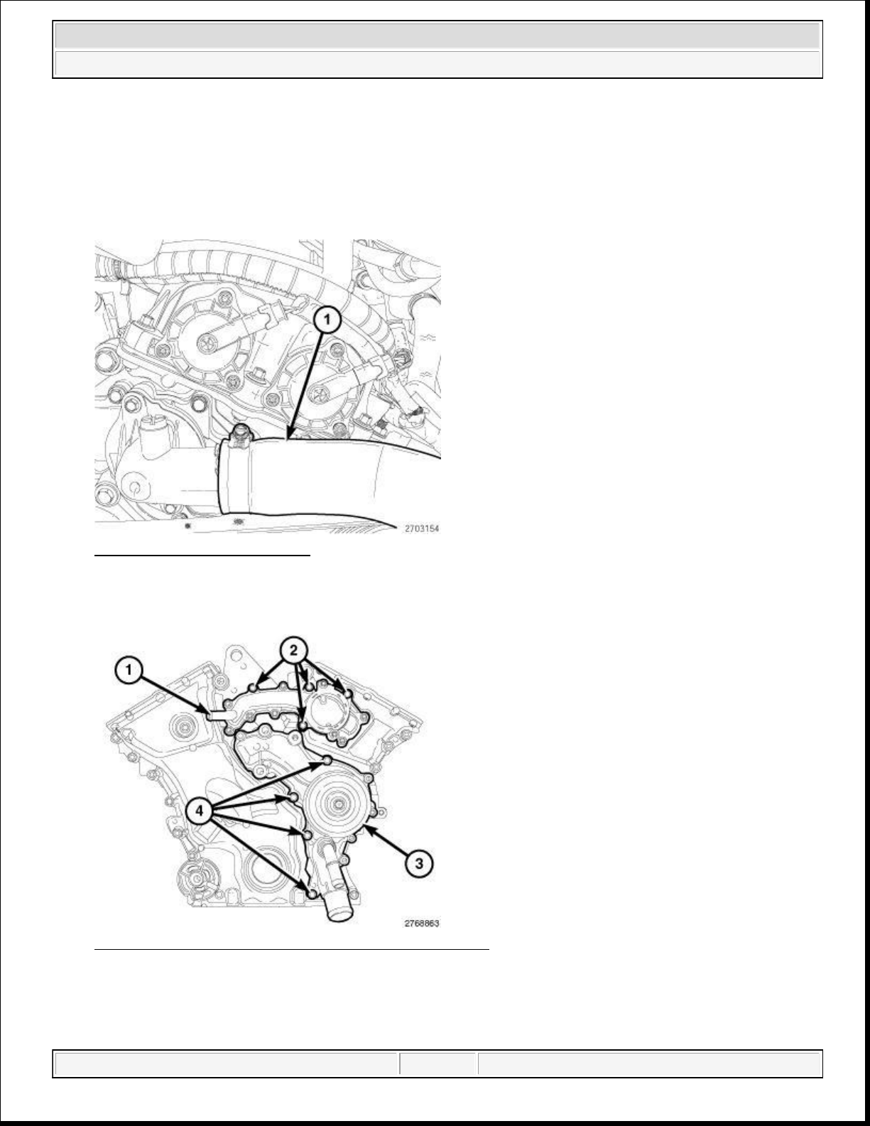
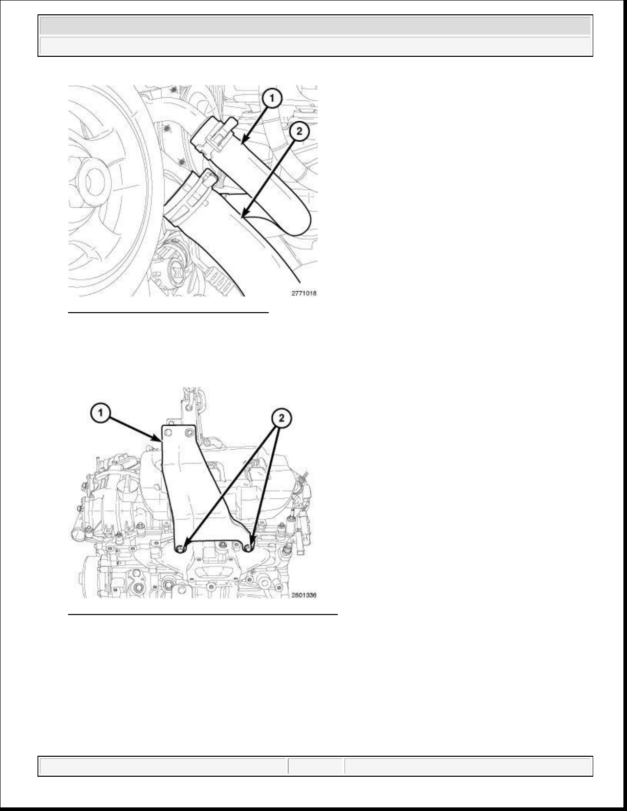
Fig. 41: Upper Radiator Hose
Courtesy of CHRYSLER GROUP, LLC
75. Remove the upper radiator hose (1) from the engine thermostat housing and position aside.
Fig. 42: Coolant Outlet Housing, Water Pump & Bolts
Courtesy of CHRYSLER GROUP, LLC
domingo, 10 de octubre de 2021 04:48:07 p. m. Page 44 © 2011 Mitchell Repair Information Company, LLC.
Page 45
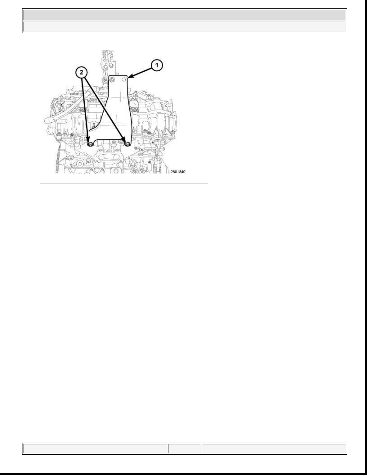
21 N.m (15 ft. lbs.).
2014 RAM 1500 Laramie
2014 ENGINE 3.6L - Service Information - Ram Pickup
Fig. 43: Radiator Hose & Heater Hose
Courtesy of CHRYSLER GROUP, LLC
77. Remove the heater hose (1) at the water pump and position aside.
78. Remove the lower radiator hose (2) from the engine coolant pump housing and position aside.
Fig. 44: Driver Side Engine Lifting Bracket & Bolts
Courtesy of CHRYSLER GROUP, LLC
79. Install the Driver Side Engine Lifting Bracket (special tool #10242-1, Brackets, Engine Lifting, Left Side)
(1) on the LH cylinder head with bolts (2) provided with the Engine Lifting Bracket. Tighten the bolts to
domingo, 10 de octubre de 2021 04:48:07 p. m. Page 45 © 2011 Mitchell Repair Information Company, LLC.
Page 46
INSTALLATION
2014 RAM 1500 Laramie
2014 ENGINE 3.6L - Service Information - Ram Pickup
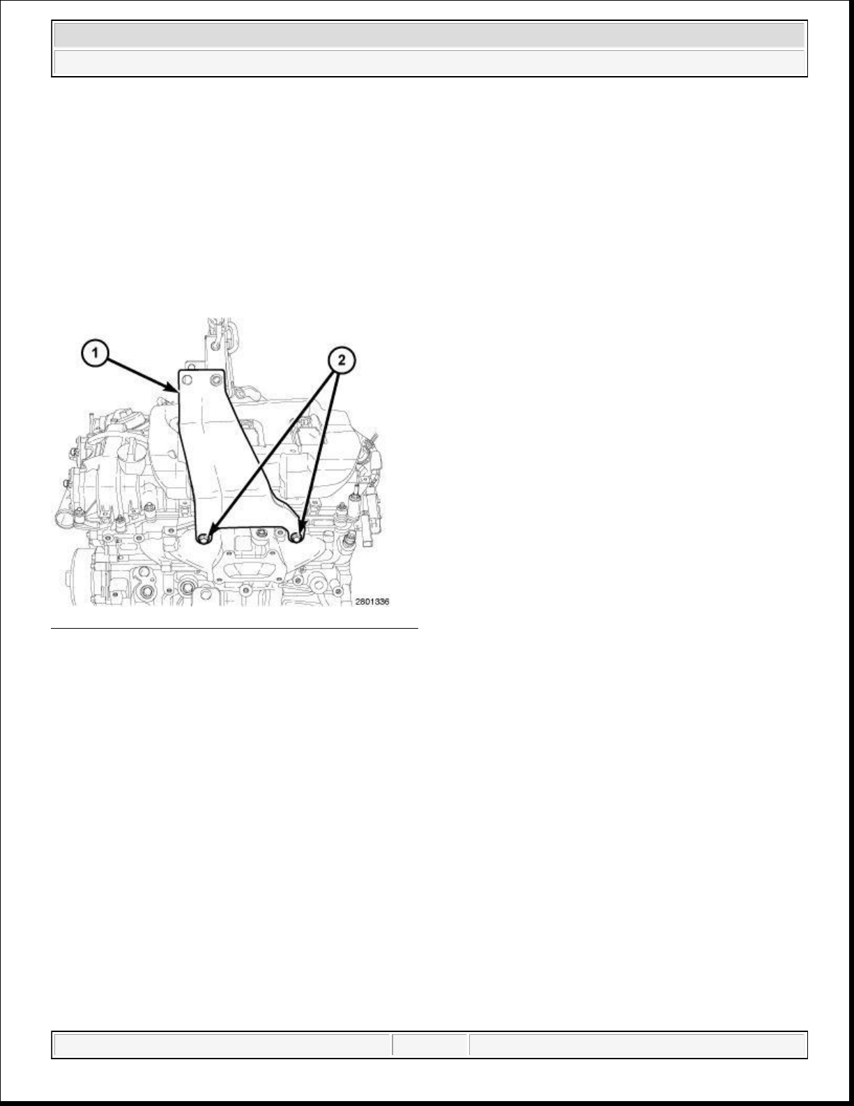
Fig. 45: Passenger Side Engine Lifting Bracket & Bolts
Courtesy of CHRYSLER GROUP, LLC
80. Install the Passenger Side Engine Lifting Bracket (special tool #10242-2, Brackets, Engine Lifting, Right
Side) (1) on the RH cylinder head with bolts (2) from the Engine Lifting Bracket. Tighten the bolts to 21
N.m (15 ft. lbs.).
81. Reposition the main wire harness to the rear of the engine compartment.
Right engine mount shown in illustration, left engine mount similar.
82. Support the transmission with a suitable jack.
CAUTION: While slowly separating the engine from the vehicle, constant checks
must be made to assure proper positioning and that no damage to
other components or wiring harnesses occur during separation.
83. Carefully remove the engine from the engine bay area.
84. If required, remove the following components for installation on the replacement engine:
Lower intake manifold
Start/Stop solenoid
LH engine mount bracket
RH engine mount bracket
Accessory drive belt tensioner
Generator
Flywheel or flexplate
Block heater (if equipped)
domingo, 10 de octubre de 2021 04:48:07 p. m. Page 46 © 2011 Mitchell Repair Information Company, LLC.
Page 47
INSTALLATION
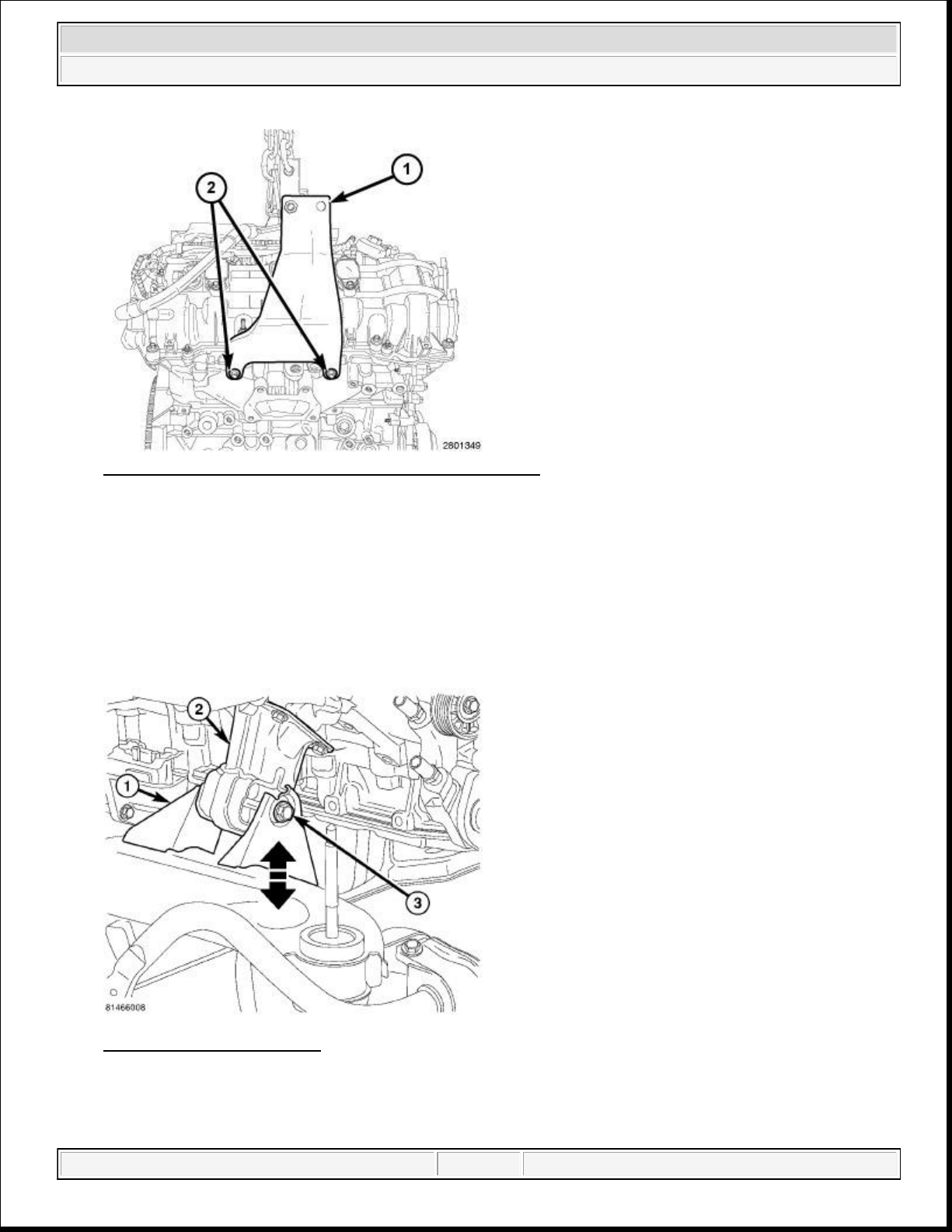
21 N.m (15 ft. lbs.).
2014 RAM 1500 Laramie
2014 ENGINE 3.6L - Service Information - Ram Pickup
CAUTION: If the original engine has experienced a catastrophic failure or an
individual failure with the piston, cylinder bore, engine block, valve or
valve seat, the intake manifold MUST be replaced with a new manifold.
NOTE: If installing a replacement engine, transfer components such as engine mount
isolators, block heater, accessories, heater hoses and tubes to the replacement
engine.
Fig. 46: Driver Side Engine Lifting Bracket & Bolts
Courtesy of CHRYSLER GROUP, LLC
1. Install the Driver Side Engine Lifting Bracket (special tool #10242-1, Brackets, Engine Lifting, Left Side)
(1) on the LH cylinder head with bolts (2) provided with the Engine Lifting Bracket. Tighten the bolts to
domingo, 10 de octubre de 2021 04:48:07 p. m. Page 47 © 2011 Mitchell Repair Information Company, LLC.
Page 48
4.
2014 RAM 1500 Laramie
2014 ENGINE 3.6L - Service Information - Ram Pickup
Fig. 47: Passenger Side Engine Lifting Bracket & Bolts
Courtesy of CHRYSLER GROUP, LLC
2. Install the Passenger Side Engine Lifting Bracket (special tool #10242-2, Brackets, Engine Lifting, Right
Side) (1) on the RH cylinder head with bolts (2) from the Engine Lifting Bracket. Tighten the bolts to 21
N.m (15 ft. lbs.).
3. Reposition the main wire harness to the rear of the engine compartment.
NOTE: Right engine mount shown in illustration, left engine mount similar.
Fig. 48: Engine Mount Bolt
Courtesy of CHRYSLER GROUP, LLC
2WD Vehicle,
domingo, 10 de octubre de 2021 04:48:07 p. m. Page 48 © 2011 Mitchell Repair Information Company, LLC.
Page 49
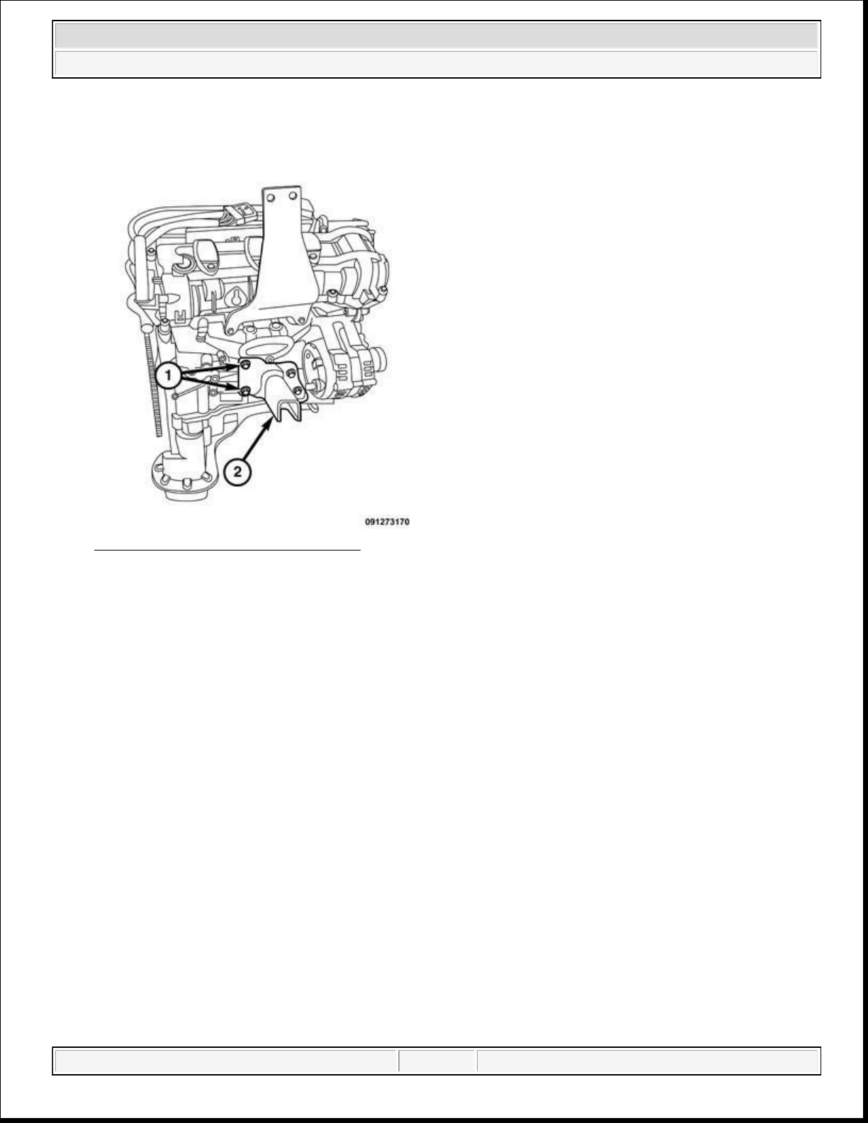
Position the engine mount (2) onto the engine support (1). Tighten the bolt (3) to 95 N.m (70 ft. lbs.).
2014 RAM 1500 Laramie
2014 ENGINE 3.6L - Service Information - Ram Pickup
Fig. 49: Engine Mount Bracket Bolts
Courtesy of CHRYSLER GROUP, LLC
5. If removed, install the engine mount brackets. Tighten the bolts (1) to 61 N.m (45 ft. lbs.).
6. Position the engine in the vehicle. Align the two outer engine mount bolts to the engine mount bracket
(2).
domingo, 10 de octubre de 2021 04:48:07 p. m. Page 49 © 2011 Mitchell Repair Information Company, LLC.
Page 50
2014 RAM 1500 Laramie
2014 ENGINE 3.6L - Service Information - Ram Pickup
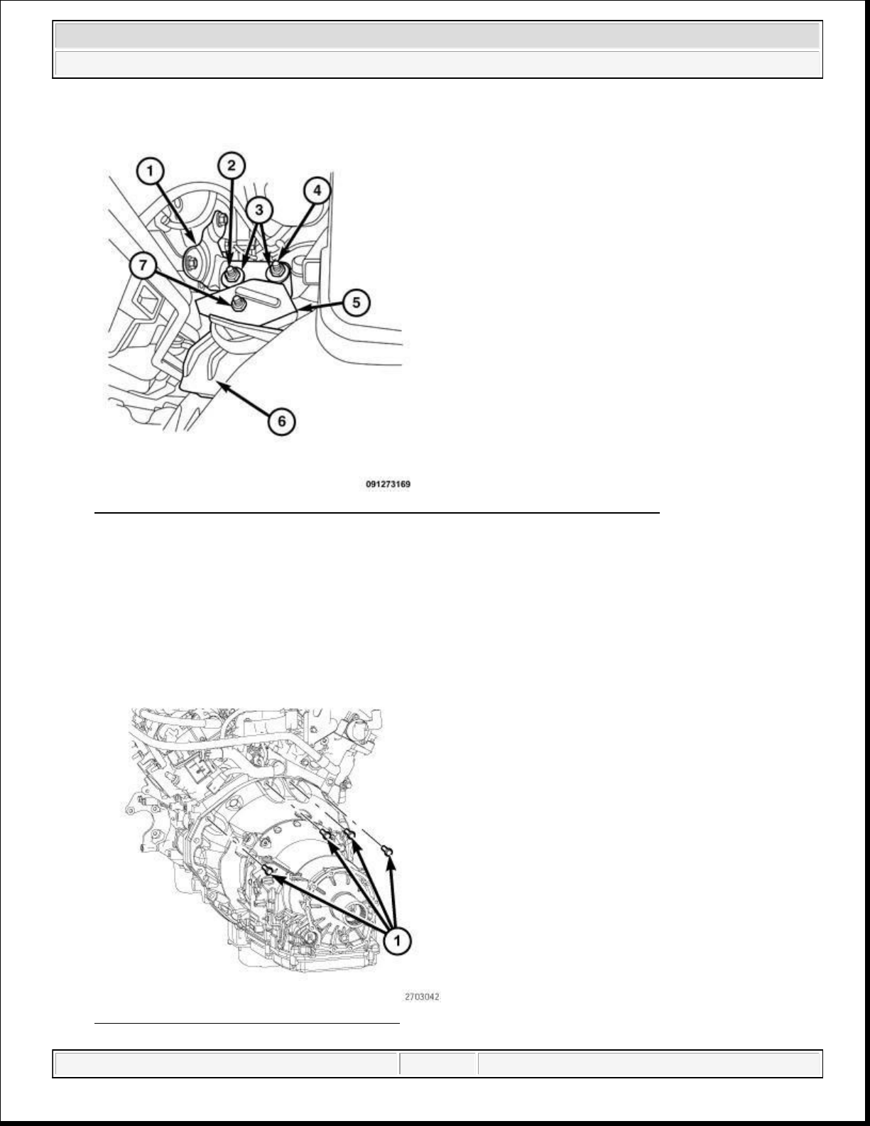
Fig. 50: Remove/Install Engine Mount, Heat Shield And Engine Bracket Bolts
Courtesy of CHRYSLER GROUP, LLC
7. Align the left and right engine mount isolators (6) within the frame mounting brackets and lower the
engine so the weight is resting on the outer mounting bolts (4).
8. Install the inner engine mount to bracket through bolt (2).
9. Raise the vehicle.
10. Tighten the left and right engine mount nuts (3) to 61 N.m (45 ft. lbs.).
11. Install the engine mount heat shield (5). Tighten the nut to 12 N.m (106 in. lbs.).
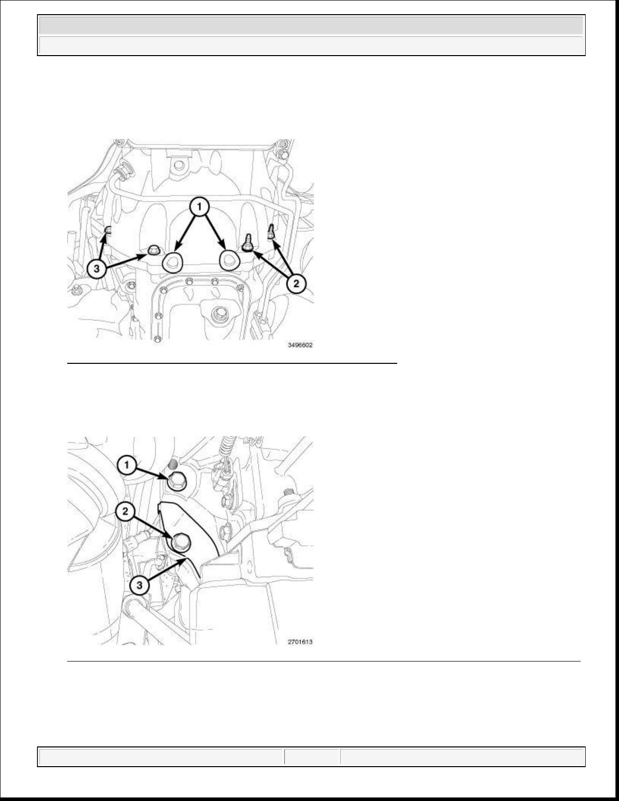
Fig. 51: Upper Transmission Engine Bolts
domingo, 10 de octubre de 2021 04:48:07 p. m. Page 50 © 2011 Mitchell Repair Information Company, LLC.
Page 51
Courtesy of CHRYSLER GROUP, LLC
16.
Install the torque converter dust shield (3) with the bolt (2). Tighten the bolt to 12 N.m (106 in. lbs.).
2014 RAM 1500 Laramie
2014 ENGINE 3.6L - Service Information - Ram Pickup
12. Install the four upper transmission to engine bolts (1). Tighten the bolts to 55 N.m (41 ft. lbs.).
Fig. 52: Rubber Plugs & Transmission-To-Engine Oil Pan Bolts
Courtesy of CHRYSLER GROUP, LLC
13. Install four transmission to the engine oil pan bolts (2 and 3) and tighten to 55 N.m (41 ft. lbs.).
14. Install two rubber plugs (1) covering the rear oil seal retainer flange bolts.
Fig. 53: Side Engine-To-Transmission Bolt, Transmission Dust Shield Retaining Bolt & Dust Shield
Courtesy of CHRYSLER GROUP, LLC
15. Install the side engine to transmission bolt (1). Tighten the bolt to 55 N.m (41 ft. lbs.).
domingo, 10 de octubre de 2021 04:48:07 p. m. Page 51 © 2011 Mitchell Repair Information Company, LLC.
Page 52
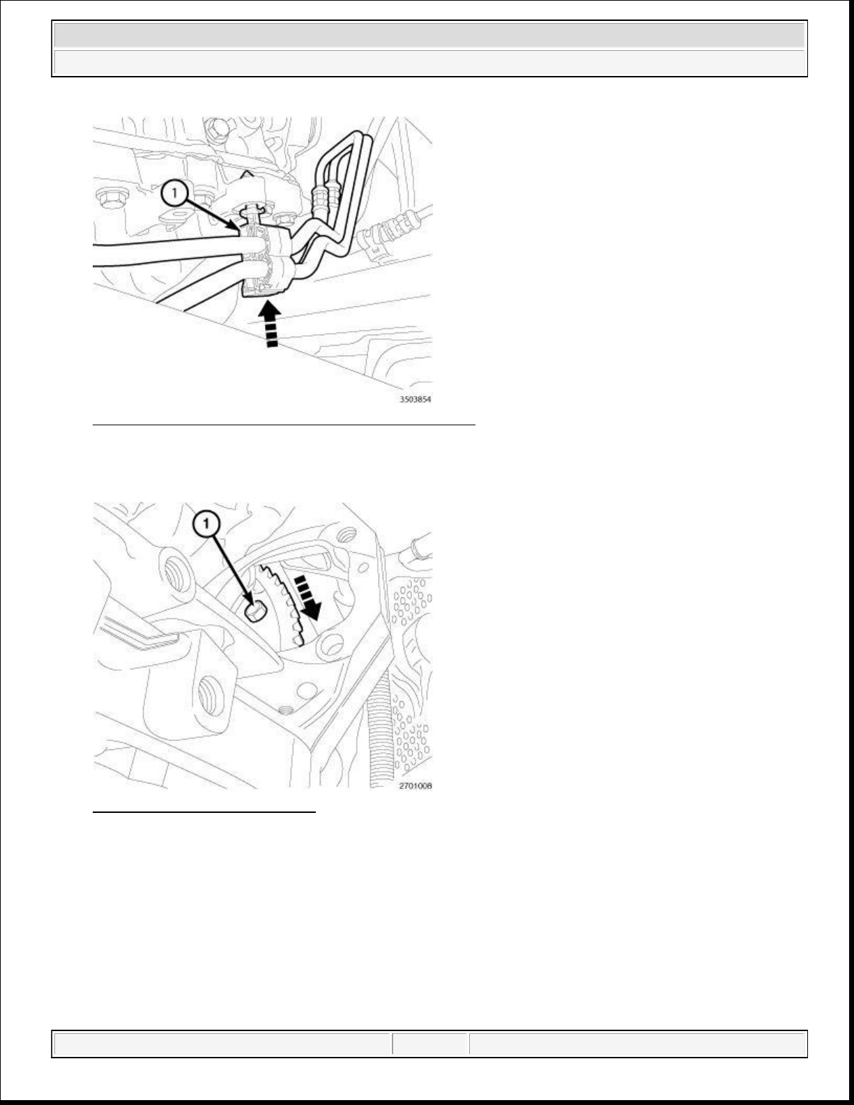
six torque converter bolts (1) through the starter mounting. Tighten the bolts to 42 N.m (31 ft. lbs.).
2014 RAM 1500 Laramie
2014 ENGINE 3.6L - Service Information - Ram Pickup
Fig. 54: Engaging Transmission Cooler Line Retainer
Courtesy of CHRYSLER GROUP, LLC
17. Install the transmission cooler line retainer (1) to the oil pan flange.
Fig. 55: Torque Converter Bolt
Courtesy of CHRYSLER GROUP, LLC
18. If equipped with an automatic transmission, rotate the crankshaft in a clockwise direction and install the
domingo, 10 de octubre de 2021 04:48:07 p. m. Page 52 © 2011 Mitchell Repair Information Company, LLC.
Page 53
2014 RAM 1500 Laramie
2014 ENGINE 3.6L - Service Information - Ram Pickup
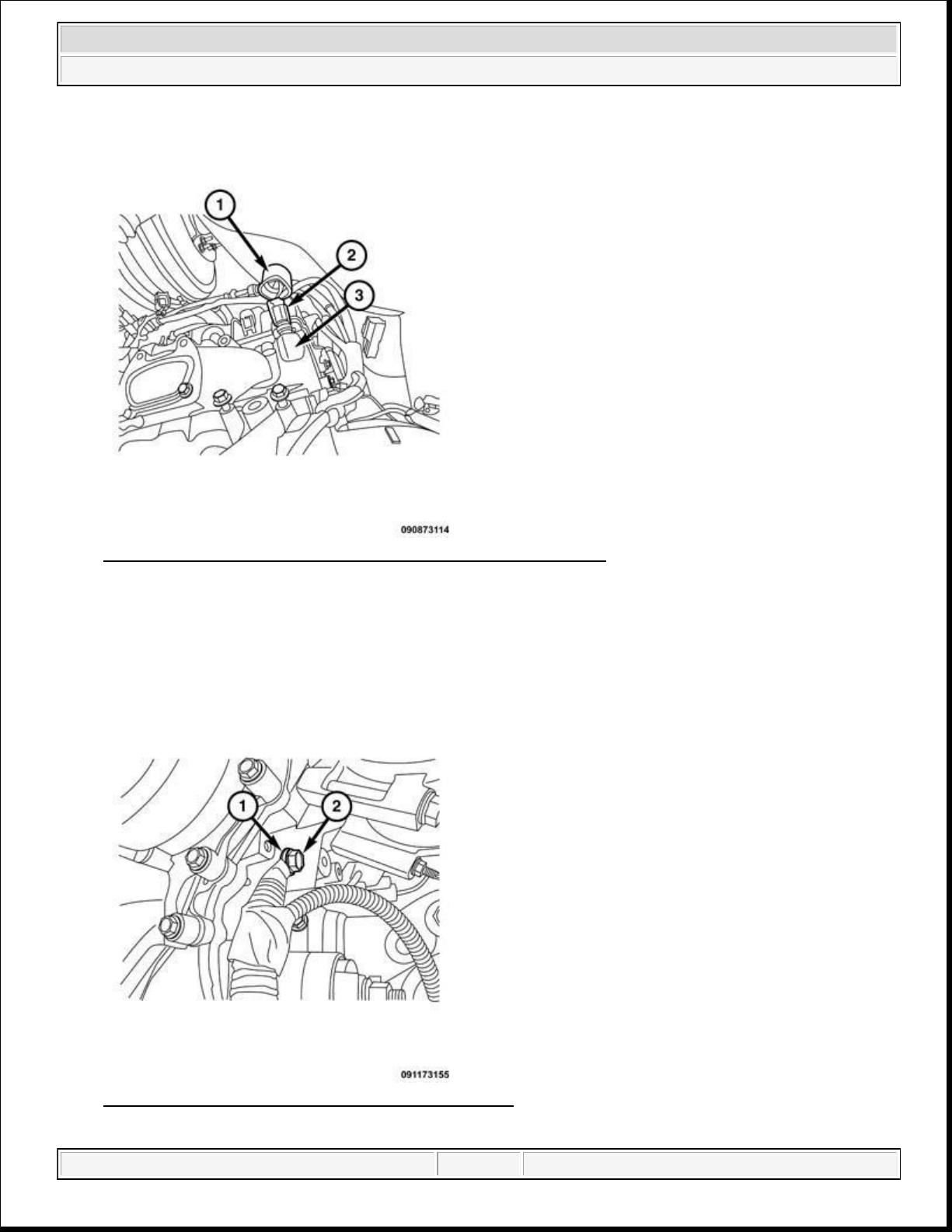
Fig. 56: Identifying Engine Coolant Temperature Sensor (3.6L)
Courtesy of CHRYSLER GROUP, LLC
19. Connect the temperature sensor electrical connector (2).
20. Reposition the temperature sensor heat shield cover (1).
Fig. 57: Removing/Installing Battery Ground Cable
Courtesy of CHRYSLER GROUP, LLC
domingo, 10 de octubre de 2021 04:48:07 p. m. Page 53 © 2011 Mitchell Repair Information Company, LLC.
Page 54
2014 RAM 1500 Laramie
2014 ENGINE 3.6L - Service Information - Ram Pickup
21. Install the battery ground (1) to the engine block. Tightened to 12 N.m (106 in. lbs.).
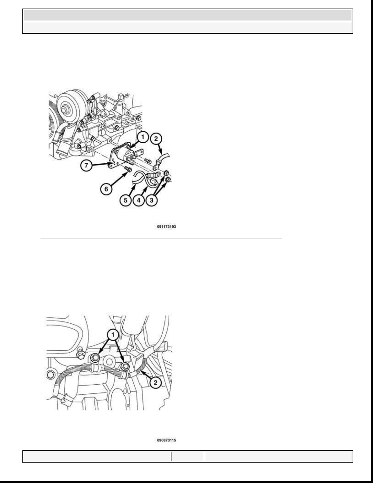
Fig. 58: Stop/Start Solenoid, Electrical Connector And Battery Positive Cable
Courtesy of CHRYSLER GROUP, LLC
22. Install the battery positive cable (4) to the stop/start solenoid (1).
23. Connect the stop/start solenoid electrical connector (4).
domingo, 10 de octubre de 2021 04:48:07 p. m. Page 54 © 2011 Mitchell Repair Information Company, LLC.
Page 55
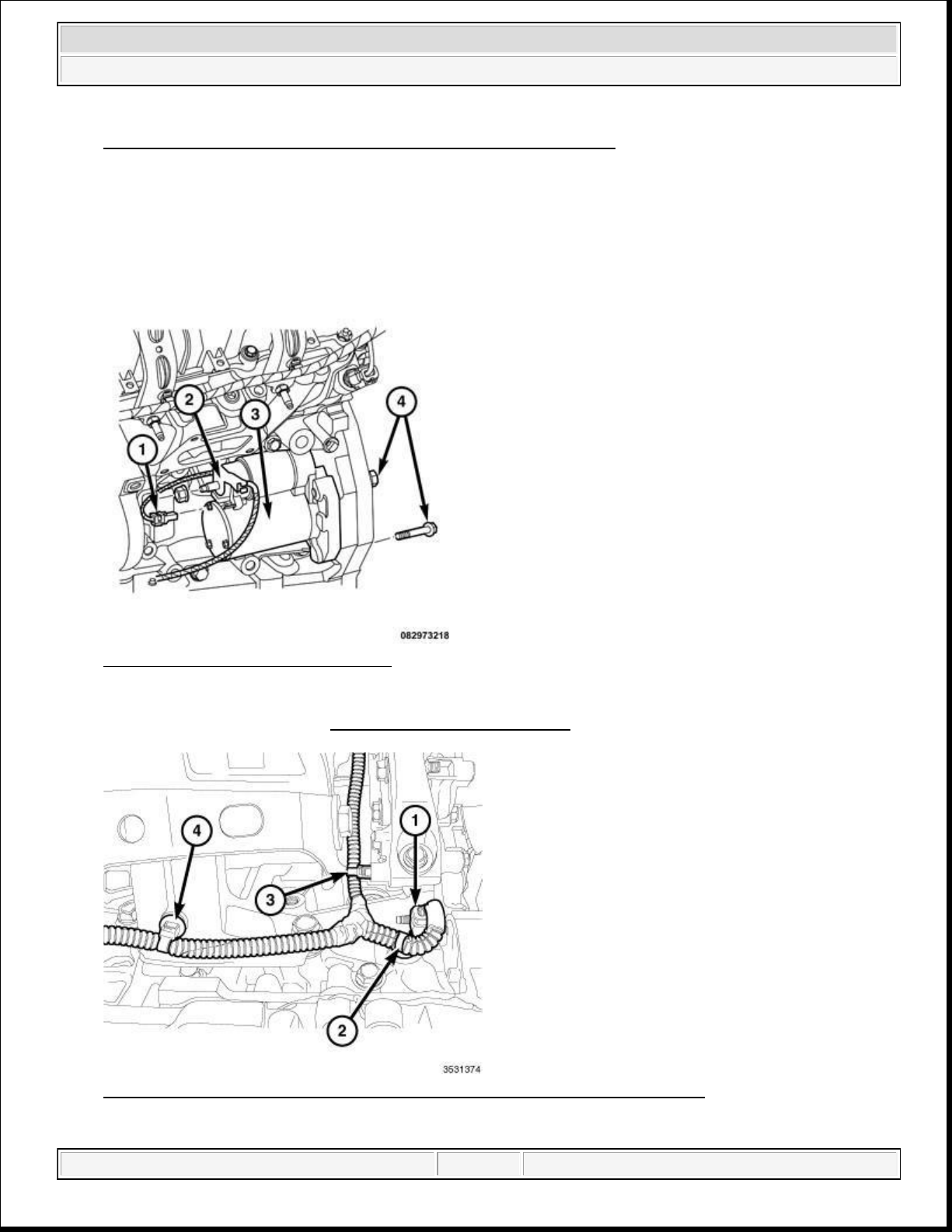
Fig. 59: Starter Solenoid Wiring Harness
-To-
Engine Block Bolts
Courtesy of CHRYSLER GROUP, LLC
2014 RAM 1500 Laramie
2014 ENGINE 3.6L - Service Information - Ram Pickup
Courtesy of CHRYSLER GROUP, LLC
24. Install the starter solenoid wiring harness (2) loom bolts (1). Tighten the bolts to 12 N.m (106 in. lbs.).
Fig. 60: Removing/Installing Starter
Courtesy of CHRYSLER GROUP, LLC
25. Install the starter (3). Refer to STARTER, INSTALLATION .
Fig. 61: Oil Pump Solenoid Electrical Connector & Wire Harness Retainers
domingo, 10 de octubre de 2021 04:48:07 p. m. Page 55 © 2011 Mitchell Repair Information Company, LLC.
Page 56
2014 RAM 1500 Laramie
2014 ENGINE 3.6L - Service Information - Ram Pickup
26. Connect the oil pump solenoid electrical connector (1).
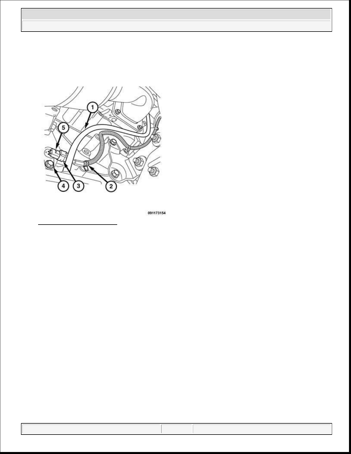
Fig. 62: CKP Sensor - 3.6L
Courtesy of CHRYSLER GROUP, LLC
27. Connect the crank shaft positioning sensor electrical connector (3).
28. Install the wiring harness retainers (2).
29. Install the transmission heater hose to the thermal management line.
domingo, 10 de octubre de 2021 04:48:07 p. m. Page 56 © 2011 Mitchell Repair Information Company, LLC.
Page 57
2014 RAM 1500 Laramie
2014 ENGINE 3.6L - Service Information - Ram Pickup
Fig. 63: Thermal Management Lines And Bolt
Courtesy of CHRYSLER GROUP, LLC
30. Install the thermal management line bracket (1) to the transmission bell housing. Tighten the bolt (2) to
12 N.m (106 in. lbs.).
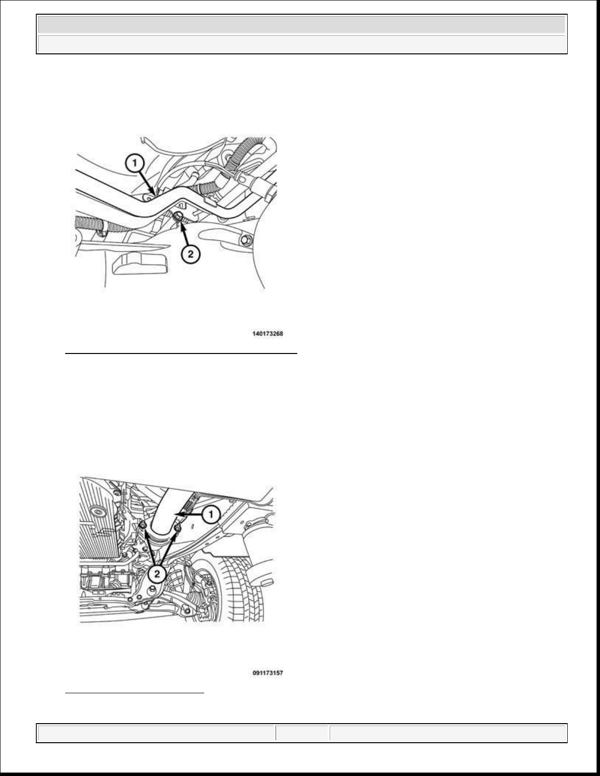
Fig. 64: Y-Pipe Flange Nuts
Courtesy of CHRYSLER GROUP, LLC
domingo, 10 de octubre de 2021 04:48:07 p. m. Page 57 © 2011 Mitchell Repair Information Company, LLC.
Page 58
2014 RAM 1500 Laramie
2014 ENGINE 3.6L - Service Information - Ram Pickup
31. Position the catalytic convertor to the cylinder heads.
32. Align the Y-pipe (1) to the catalytic convertor flanges. Tighten the flange nuts to 23 N.m (17 ft. lbs.).
33. Partially lower the vehicle.
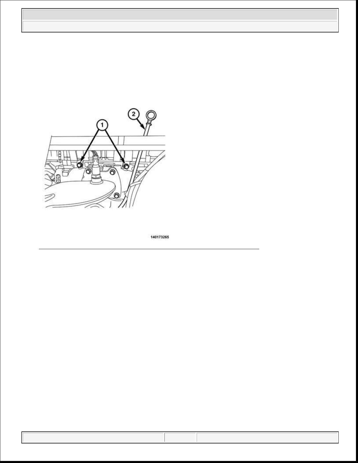
Fig. 65: Coolant Heater Tubes-To-Cylinder Head Bolts And Oil Indicator
Courtesy of CHRYSLER GROUP, LLC
34. Align the heater line support braces to the right side cylinder head. Install the bolts (1) loose.
35. Install the oil indicator tube (2) into the oil pan. Align the mounting tab to the heater line brace bolt.
Tighten the bolts to 12 N.m (106 in. lbs.).
NOTE: Right catalytic converter shown in illustration, left catalytic converter
similar.
domingo, 10 de octubre de 2021 04:48:07 p. m. Page 58 © 2011 Mitchell Repair Information Company, LLC.
Page 59
2014 RAM 1500 Laramie
2014 ENGINE 3.6L - Service Information - Ram Pickup
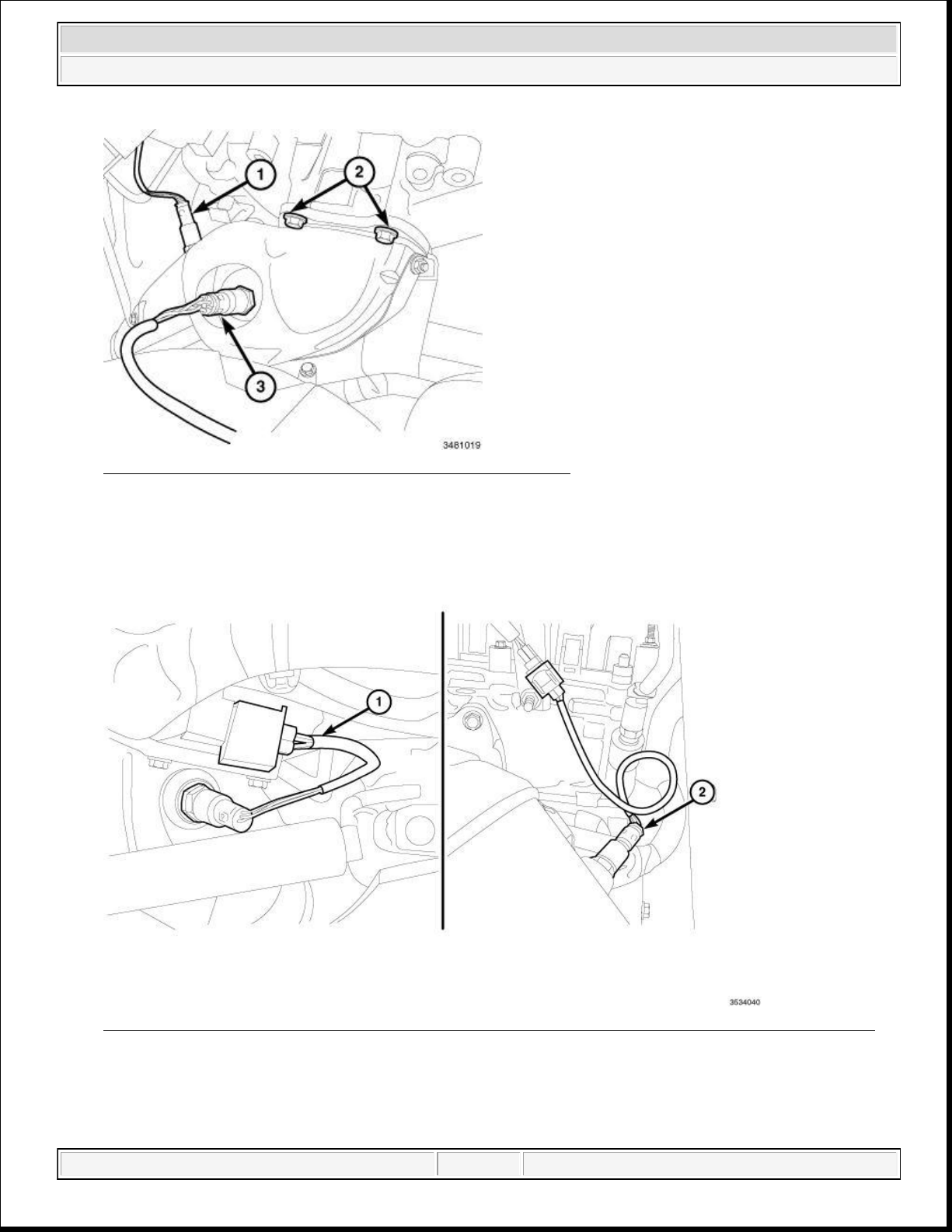
Fig. 66: Upstream & Downstream Oxygen Sensors & Bolts
Courtesy of CHRYSLER GROUP, LLC
36. Install the right and left catalytic converters upper bolts (2). Tighten the bolts to 37 N.m (27 ft. lbs.).
Fig. 67: Left Upstream Oxygen Sensor & Left Downstream Oxygen Sensor Electrical Connectors
Courtesy of CHRYSLER GROUP, LLC
37. Connect the right and left upstream (1) and downstream (2) oxygen sensor connectors to the main wire
harness.
domingo, 10 de octubre de 2021 04:48:07 p. m. Page 59 © 2011 Mitchell Repair Information Company, LLC.
Page 60
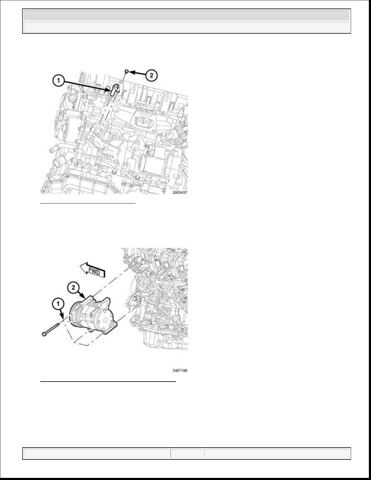
38. Lower the vehicle.
42.
Connect the A/C compressor electrical connector (2).
2014 RAM 1500 Laramie
2014 ENGINE 3.6L - Service Information - Ram Pickup
Fig. 68: Block Heater & Screw
Courtesy of CHRYSLER GROUP, LLC
39. Connect the power cord to the engine block heater (if equipped).
40. Lower the vehicle.
Fig. 69: A/C Compressor & Mounting Bolts
Courtesy of CHRYSLER GROUP, LLC
41. Install the A/C compressor (2) onto the engine. Tighten bolts to 28 N.m (21 ft. lbs.).
domingo, 10 de octubre de 2021 04:48:07 p. m. Page 60 © 2011 Mitchell Repair Information Company, LLC.
Page 61
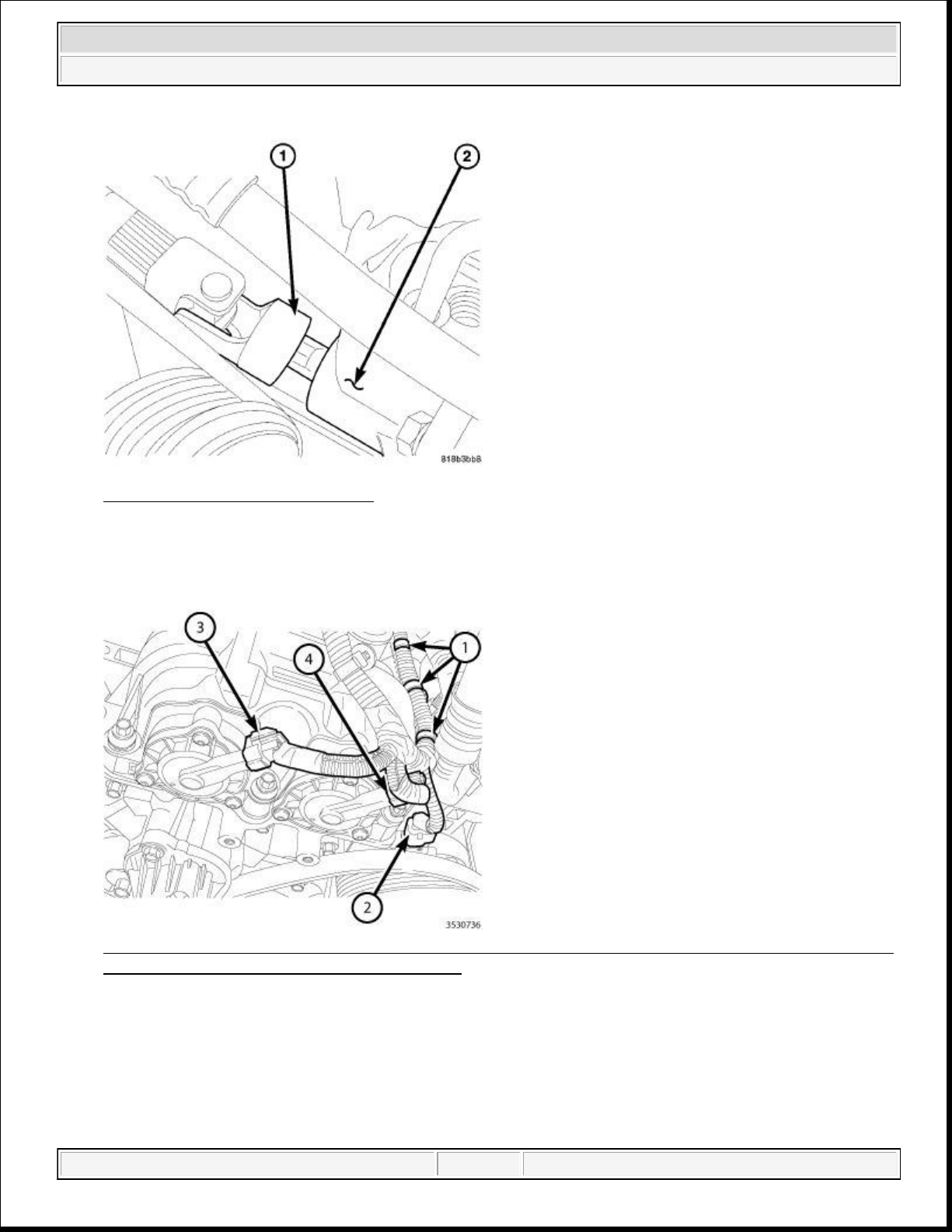
47.
Engage three wire harness retainers (1) to the left cylinder head cover.
2014 RAM 1500 Laramie
2014 ENGINE 3.6L - Service Information - Ram Pickup
Fig. 70: Lower Coupling AT Gear
Courtesy of CHRYSLER GROUP, LLC
43. Align the lower intermediate shaft coupler (1) to the steering gear (2). Tighten the bolt to 49 N.m (36 ft.
lbs.).
Fig. 71: Retainers, A/C Compressor Electrical Connector & Left Intake And Left Exhaust Variable
Valve Timing Solenoid Electrical Connectors
Courtesy of CHRYSLER GROUP, LLC
44. Route the main wire harness on the left side of the engine.
45. Connect the left exhaust variable valve timing solenoid electrical connector (4).
46. Connect the left intake variable valve timing solenoid electrical connector (3).
domingo, 10 de octubre de 2021 04:48:07 p. m. Page 61 © 2011 Mitchell Repair Information Company, LLC.
Page 62
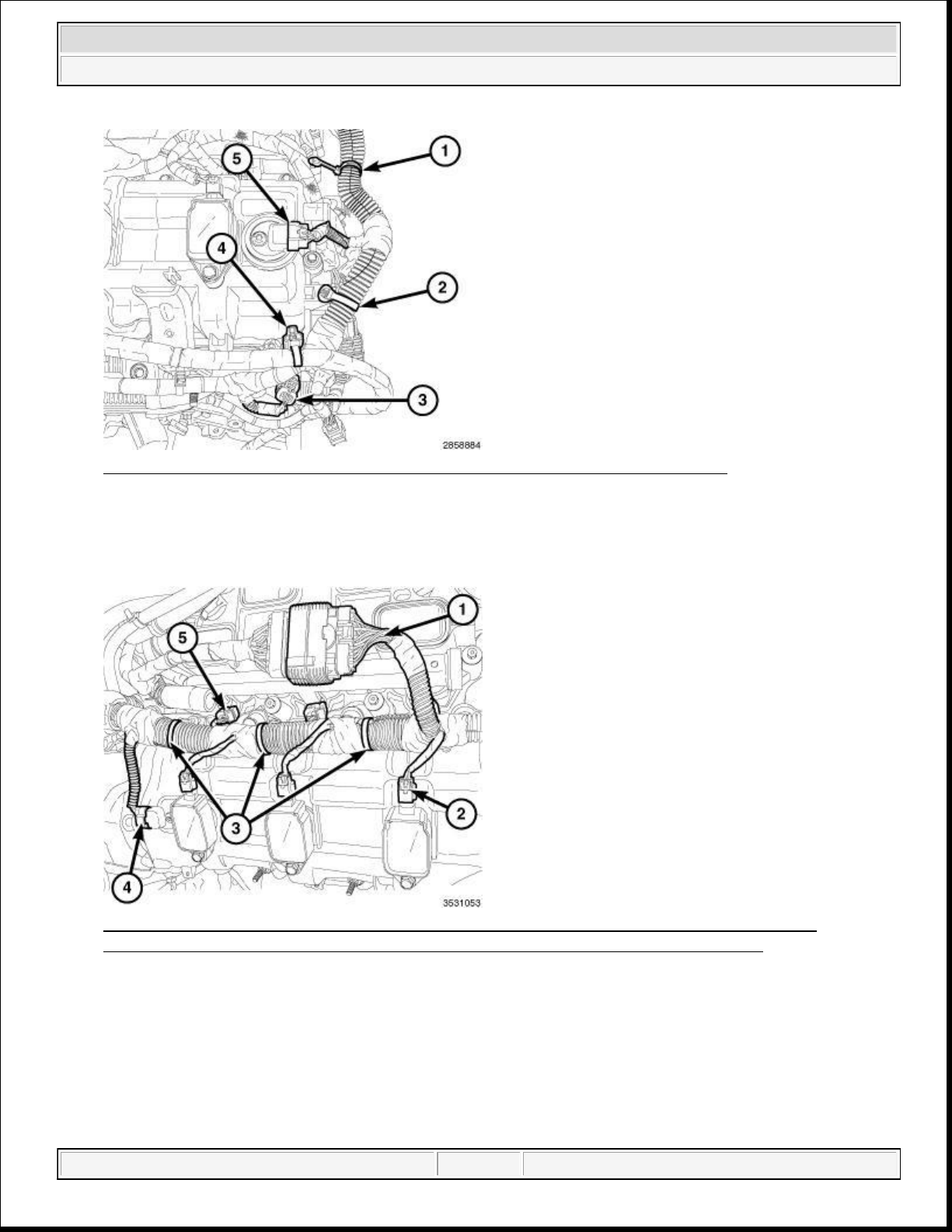
2014 RAM 1500 Laramie
2014 ENGINE 3.6L - Service Information - Ram Pickup
Fig. 72: ECT Sensor Connector, CMP Sensor & Main Wire Harness Retainers
Courtesy of CHRYSLER GROUP, LLC
48. Connect the left Camshaft Position (CMP) sensor (5).
49. Engage the main wire harness retainers (1 and 2) to the cylinder head cover mounting stud.
Fig. 73: Engine Injection/Ignition Harness, Ignition Coil Electrical Connectors, Retainers,
Camshaft Position (CMP) Sensor Connector & Fuel Injector Electrical Connectors
Courtesy of CHRYSLER GROUP, LLC
50. Route the main wire harness on the right side of the engine.
51. Connect the electrical connector (4) to the right Camshaft Position (CMP) sensor.
52. Connect three fuel injector electrical connectors (5).
53. Connect the main harness to the engine injection/ignition harness (1).
54. Engage three main wire harness retainers (3) to the right cylinder head cover.
domingo, 10 de octubre de 2021 04:48:07 p. m. Page 62 © 2011 Mitchell Repair Information Company, LLC.
Page 63
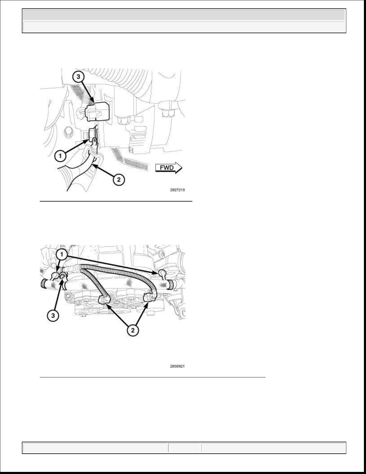
61.
Secure the ground to the rear of the cylinder heads. Tighten the bolt (2) tightened to 12 N.m (106 in. lbs.).
2014 RAM 1500 Laramie
2014 ENGINE 3.6L - Service Information - Ram Pickup
55. Connect three ignition coil electrical connectors (2).
Fig. 74: Field Circuit, B+ Terminal Nut And Wire
Courtesy of CHRYSLER GROUP, LLC
56. Install the B+ terminal to the generator stud (2). Tighten the nut (1) to 11 N.m (97 in. lbs.).
57. Connect the field circuit connector (3) to the generator.
Fig. 75: Variable Valve Timing Solenoid Connectors & Harness Retainers
Courtesy of CHRYSLER GROUP, LLC
58. Connect the right exhaust variable valve timing solenoid electrical connector (5).
59. Connect the right intake variable valve timing solenoid electrical connector (6).
60. Engage the wire harness retainers (1) to the cylinder head cover.
domingo, 10 de octubre de 2021 04:48:07 p. m. Page 63 © 2011 Mitchell Repair Information Company, LLC.
Page 64
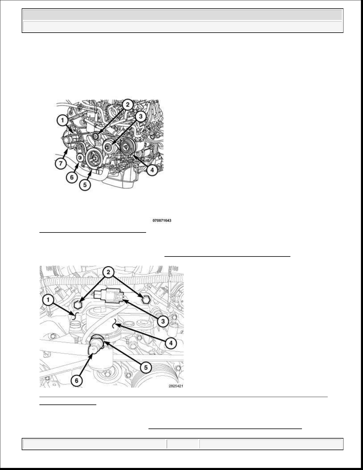
64.
Install the vacuum pump (4). Refer to
PUMP, ELECTRIC VACUUM, INSTALLATION
.
2014 RAM 1500 Laramie
2014 ENGINE 3.6L - Service Information - Ram Pickup
62. Connect the electrical connector (3) to the ignition coil capacitors.
Fig. 76: Belt Routing (3.6L Engine)
Courtesy of CHRYSLER GROUP, LLC
63. Install the accessory drive belt (1). Refer to BELT, SERPENTINE, INSTALLATION .
Fig. 77: Mounting Bracket, Bolts, Electrical Connector, Vacuum Pump, Locking Tab & QuickConnect Type End
Courtesy of CHRYSLER GROUP, LLC
domingo, 10 de octubre de 2021 04:48:07 p. m. Page 64 © 2011 Mitchell Repair Information Company, LLC.
Page 65
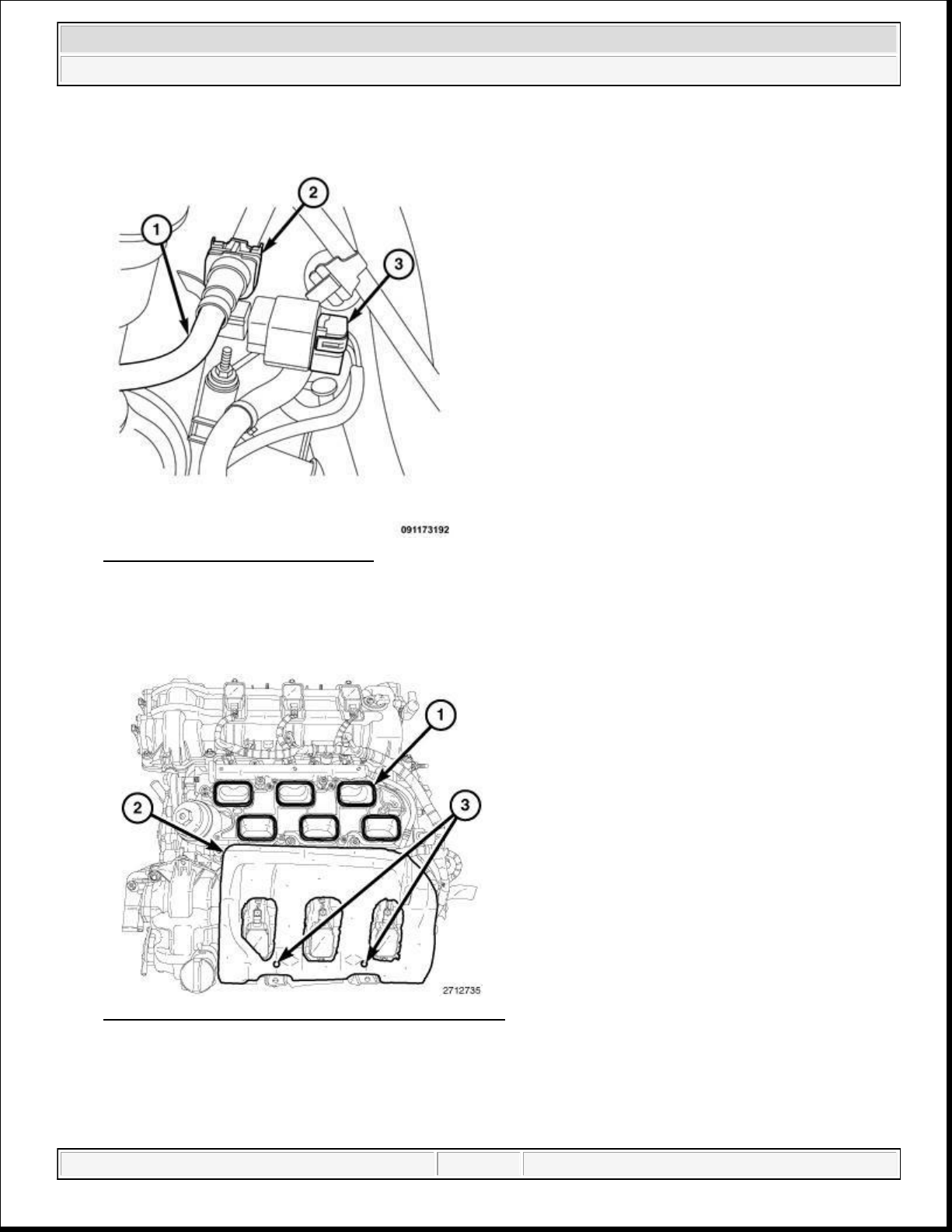
67.
Install the insulator (2) to the two alignment posts (3) on top of the LH cylinder head cover.
2014 RAM 1500 Laramie
2014 ENGINE 3.6L - Service Information - Ram Pickup
Fig. 78: Fuel Rail Pressure Sensor
Courtesy of CHRYSLER GROUP, LLC
65. Connect the fuel supply hose (2) to the fuel pressure sensor.
66. Install the fuel pressure sensor electrical connector (3).
Fig. 79: Intake Ports, Insulator & Alignment Posts
Courtesy of CHRYSLER GROUP, LLC
domingo, 10 de octubre de 2021 04:48:07 p. m. Page 65 © 2011 Mitchell Repair Information Company, LLC.
Page 66
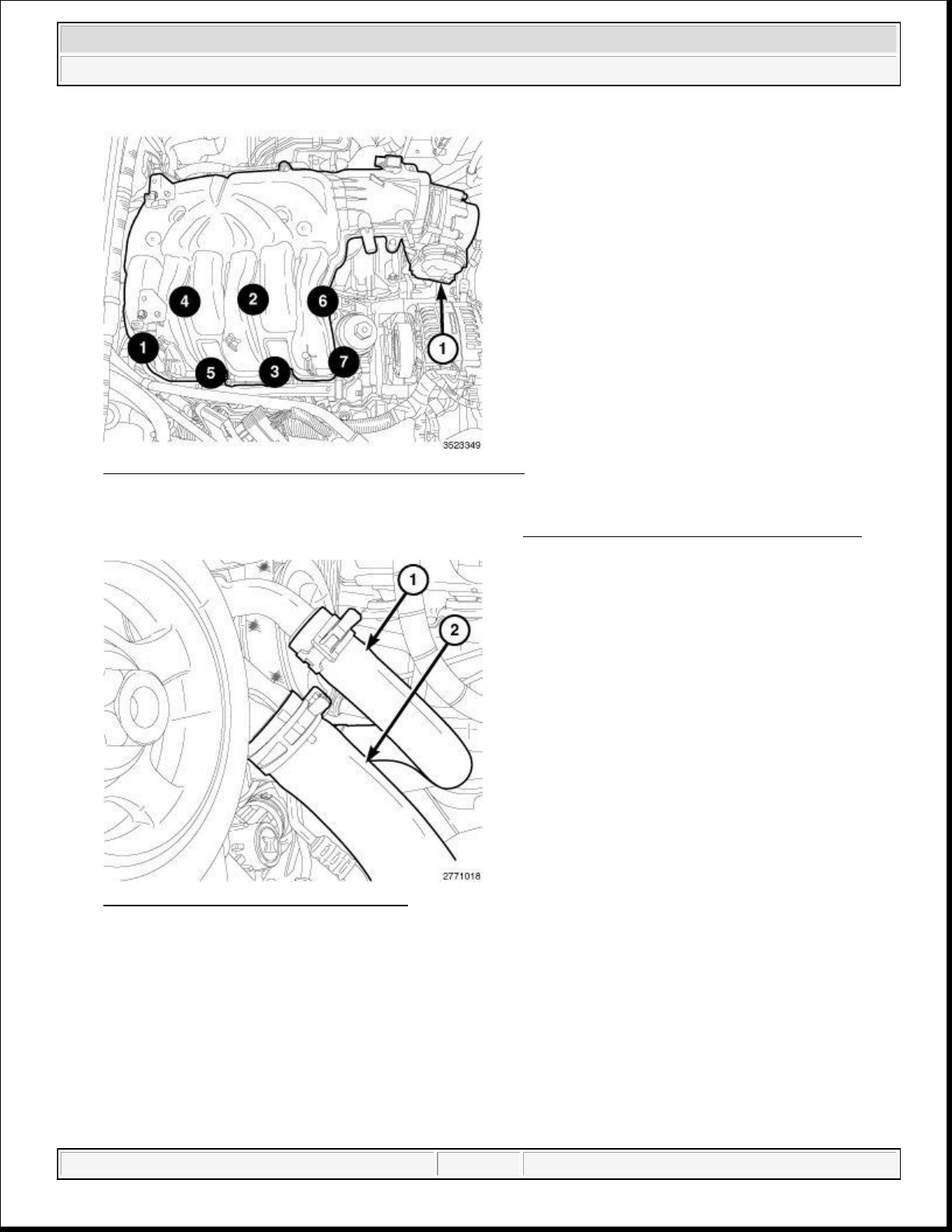
70.
Install the lower radiator hose (2) to the engine coolant pump housing.
2014 RAM 1500 Laramie
2014 ENGINE 3.6L - Service Information - Ram Pickup
Fig. 80: Upper Intake Manifold Tightening Sequence
Courtesy of CHRYSLER GROUP, LLC
68. Install the upper intake manifold and insulator. Refer to MANIFOLD, INTAKE, INSTALLATION .
Fig. 81: Radiator Hose & Heater Hose
Courtesy of CHRYSLER GROUP, LLC
69. Connect the heater core return hose (1) to the water pump.
domingo, 10 de octubre de 2021 04:48:07 p. m. Page 66 © 2011 Mitchell Repair Information Company, LLC.
Page 67
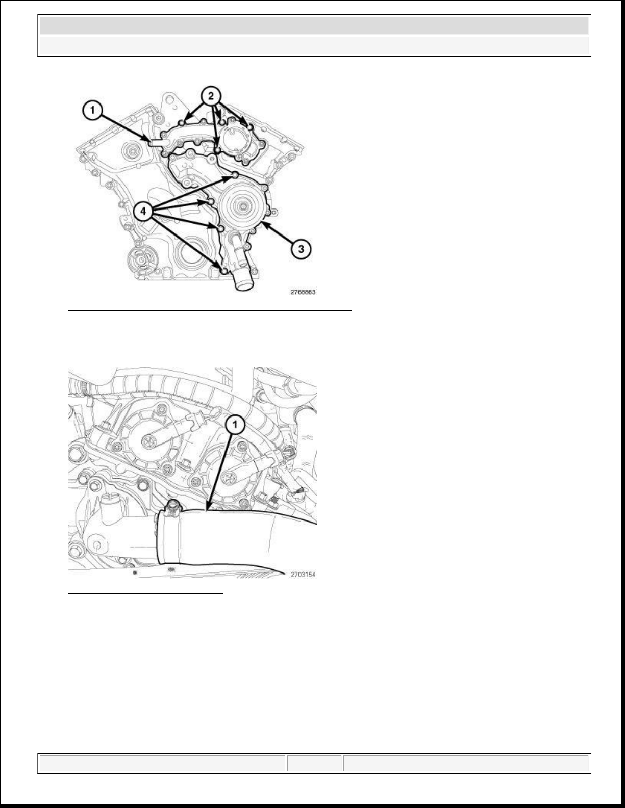
72.
Install the upper radiator hose (1) to the engine thermostat housing.
2014 RAM 1500 Laramie
2014 ENGINE 3.6L - Service Information - Ram Pickup
Fig. 82: Coolant Outlet Housing, Water Pump & Bolts
Courtesy of CHRYSLER GROUP, LLC
71. Install the heater supply hose to the coolant crossover (1).
Fig. 83: Upper Radiator Hose
Courtesy of CHRYSLER GROUP, LLC
domingo, 10 de octubre de 2021 04:48:07 p. m. Page 67 © 2011 Mitchell Repair Information Company, LLC.
Page 68
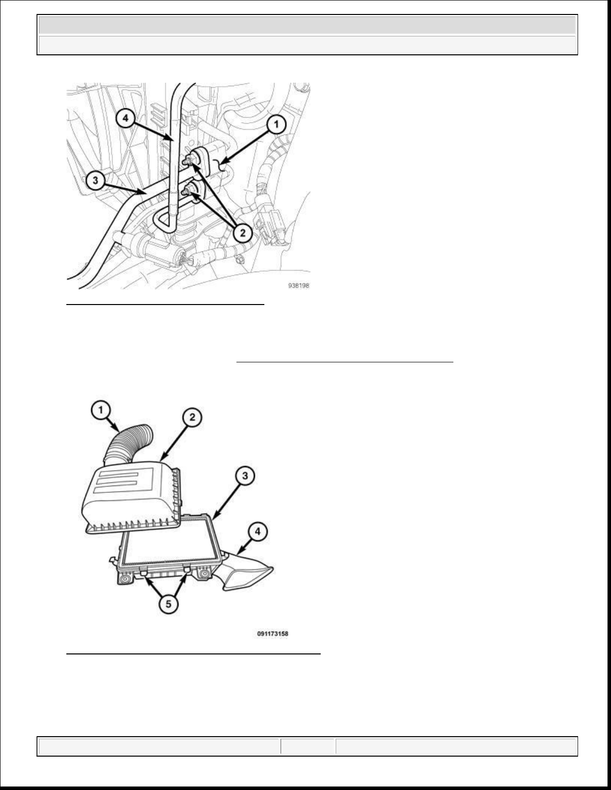
75.
Install the air cleaner lower housing assembly (4).
2014 RAM 1500 Laramie
2014 ENGINE 3.6L - Service Information - Ram Pickup
Fig. 84: A/C Discharge & Liquid Lines
Courtesy of CHRYSLER GROUP, LLC
73. Install the A/C lines to the condenser (1). Tighten the nuts (2) to 23 N.m (17 ft. lbs.).
74. Recharge the A/C system. Refer to PLUMBING, STANDARD PROCEDURE .
Fig. 85: Removing/Installing Air Filter Box Cover
Courtesy of CHRYSLER GROUP, LLC
domingo, 10 de octubre de 2021 04:48:07 p. m. Page 68 © 2011 Mitchell Repair Information Company, LLC.
Page 69
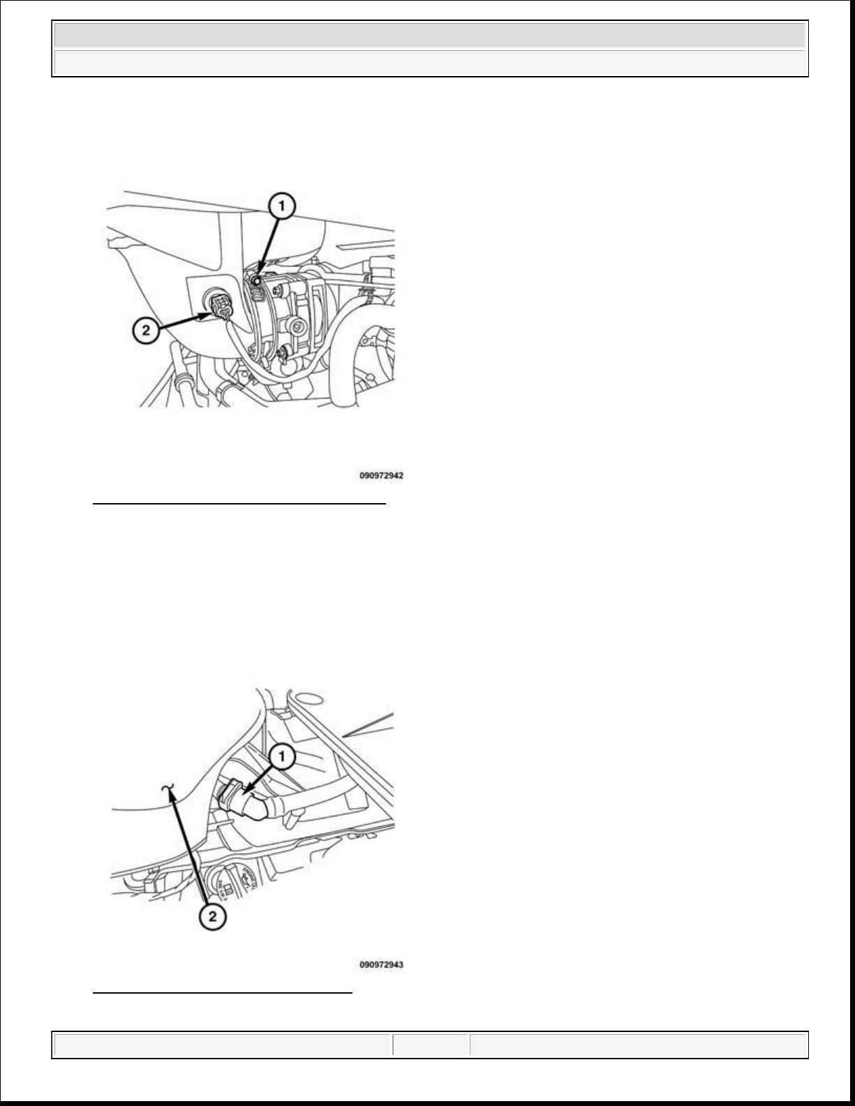
2014 RAM 1500 Laramie
2014 ENGINE 3.6L - Service Information - Ram Pickup
Fig. 86: IAT Sensor Electrical Connector
Courtesy of CHRYSLER GROUP, LLC
76. Position the air intake onto the throttle body. Hand tighten the clamp (1).
77. Install the IAT sensor electrical connector (2)
Fig. 87: Breather Tube & Resonator
Courtesy of CHRYSLER GROUP, LLC
domingo, 10 de octubre de 2021 04:48:07 p. m. Page 69 © 2011 Mitchell Repair Information Company, LLC.
Page 70
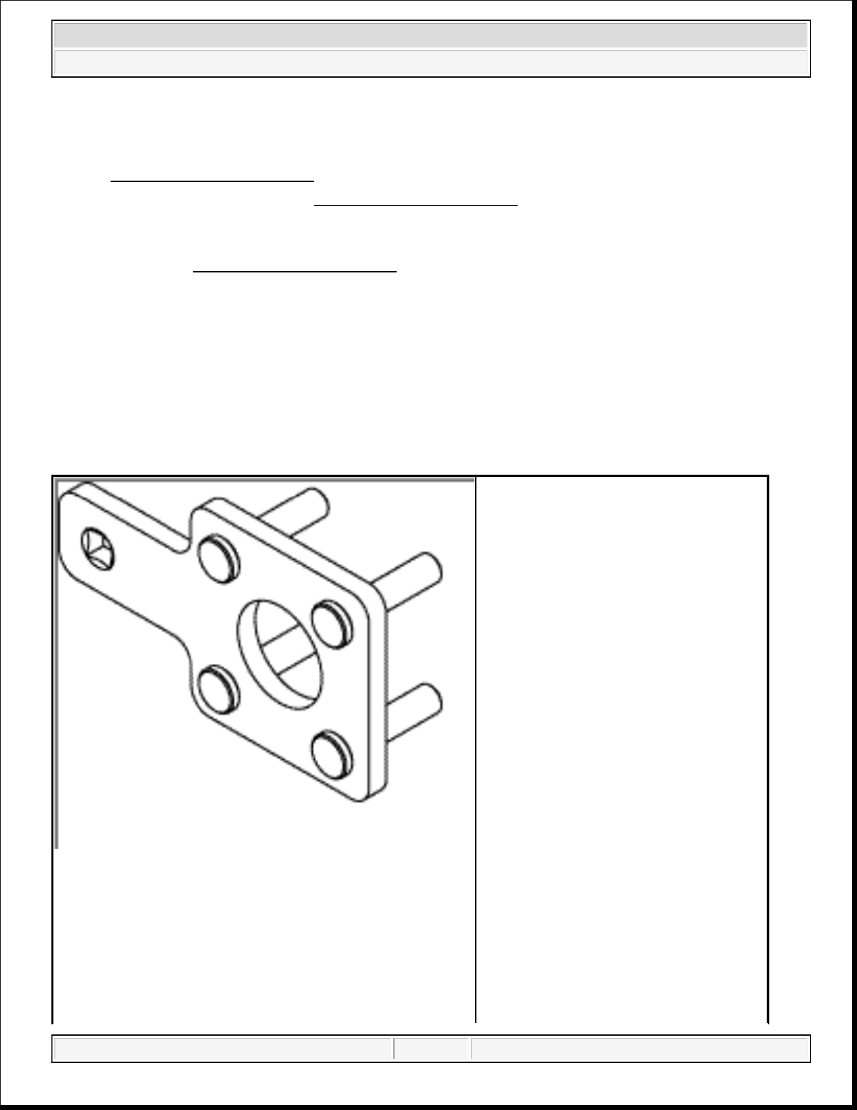
2014 RAM 1500 Laramie
2014 ENGINE 3.6L - Service Information - Ram Pickup
78. Install the breather tube (1) to the resonator (2).
79. If removed, install the oil filter and fill the engine crankcase with the proper oil to the correct level. Refer
to STANDARD PROCEDURE .
80. Fill the cooling system. Refer to STANDARD PROCEDURE .
81. Connect the negative battery cable and tighten nut to 5 N.m (45 in. lbs.).
82. Run the engine until it reaches normal operating temperature. Check cooling system for correct fluid
level. Refer to STANDARD PROCEDURE .
NOTE: The Cam/Crank Variation Relearn procedure must be performed using the scan
tool anytime there has been a repair/replacement made to a powertrain system,
for example: flywheel, valvetrain, camshaft and/or crankshaft sensors or
components.
SPECIAL TOOLS
SPECIAL TOOLS
10198 - Holder, Vibration Damper
(Originally Shipped In Kit Number(s)
10223.)
domingo, 10 de octubre de 2021 04:48:07 p. m. Page 70 © 2011 Mitchell Repair Information Company, LLC.
Page 71
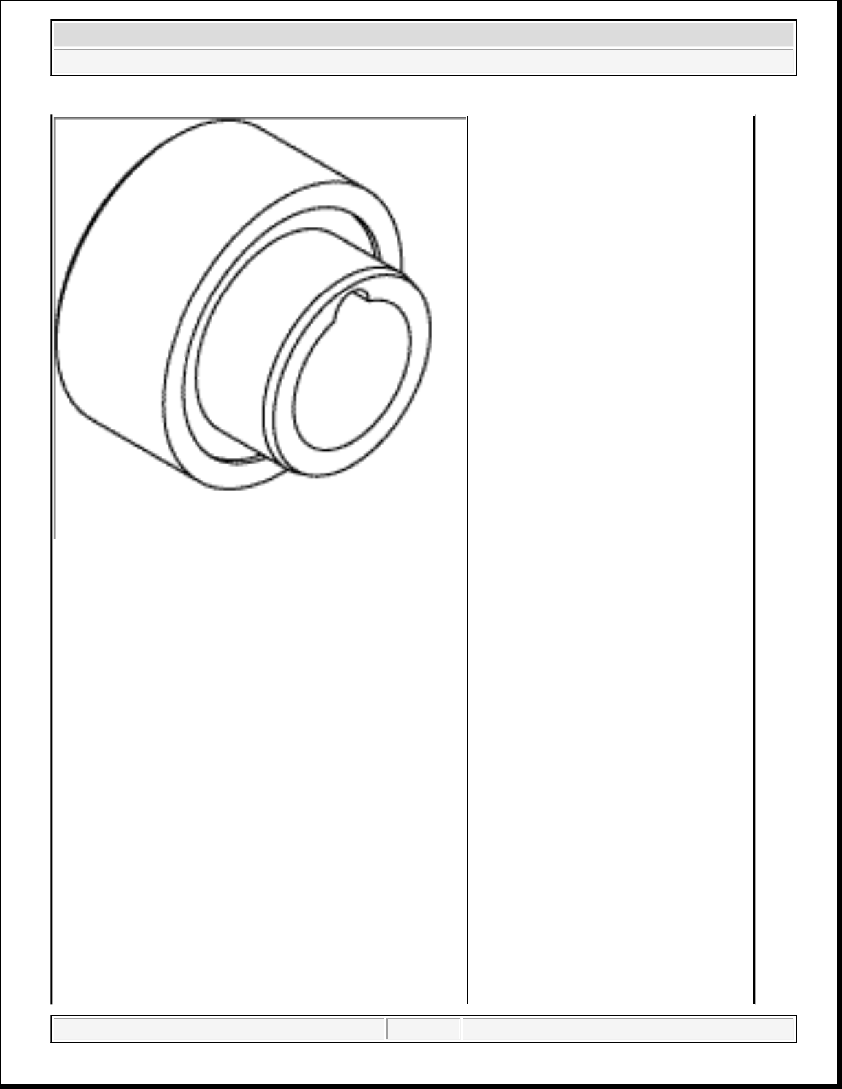
2014 RAM 1500 Laramie
2014 ENGINE 3.6L - Service Information - Ram Pickup
10199 - Installer, Crankshaft Front Oil
Seal
(Originally Shipped In Kit Number(s)
10223.)
10200-1 - Holder, Timing Chain, Left
Side
domingo, 10 de octubre de 2021 04:48:07 p. m. Page 71 © 2011 Mitchell Repair Information Company, LLC.
Page 72
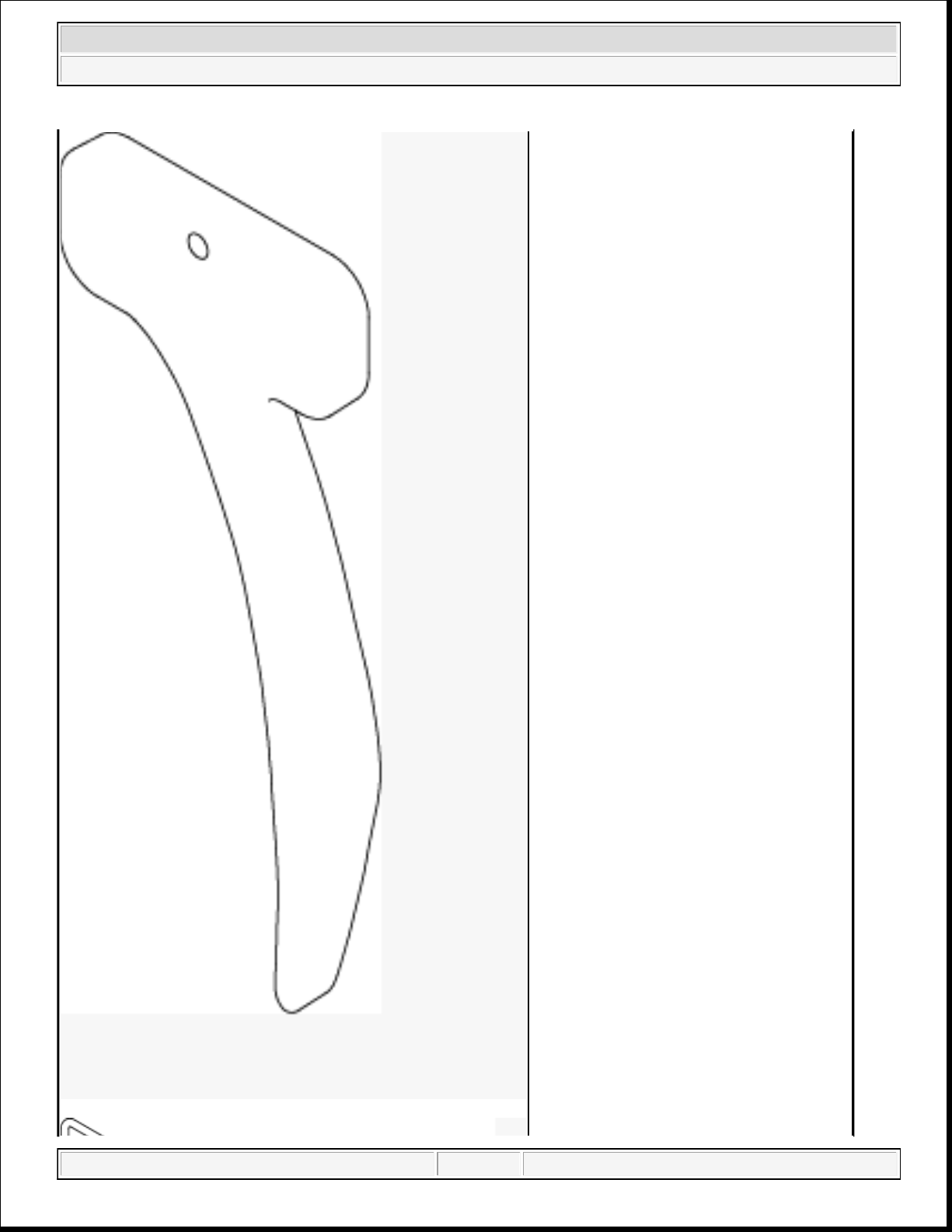
2014 RAM 1500 Laramie
2014 ENGINE 3.6L - Service Information - Ram Pickup
domingo, 10 de octubre de 2021 04:48:07 p. m. Page 72 © 2011 Mitchell Repair Information Company, LLC.
Page 73
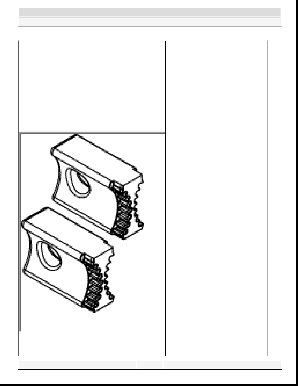
2014 RAM 1500 Laramie
2014 ENGINE 3.6L - Service Information - Ram Pickup
10200-3 - Pin
10202 - Locks, Camshaft/Phaser
domingo, 10 de octubre de 2021 04:48:07 p. m. Page 73 © 2011 Mitchell Repair Information Company, LLC.
Page 74
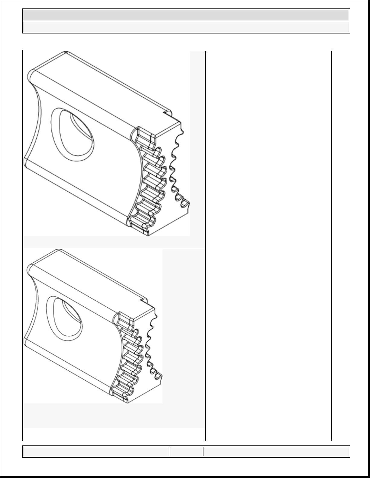
2014 RAM 1500 Laramie
2014 ENGINE 3.6L - Service Information - Ram Pickup
10202-1 - Lock, Camshaft/Phaser, Right
Side
10202-2 - Lock, Camshaft/Phaser, Left
Side
domingo, 10 de octubre de 2021 04:48:07 p. m. Page 74 © 2011 Mitchell Repair Information Company, LLC.
Page 75
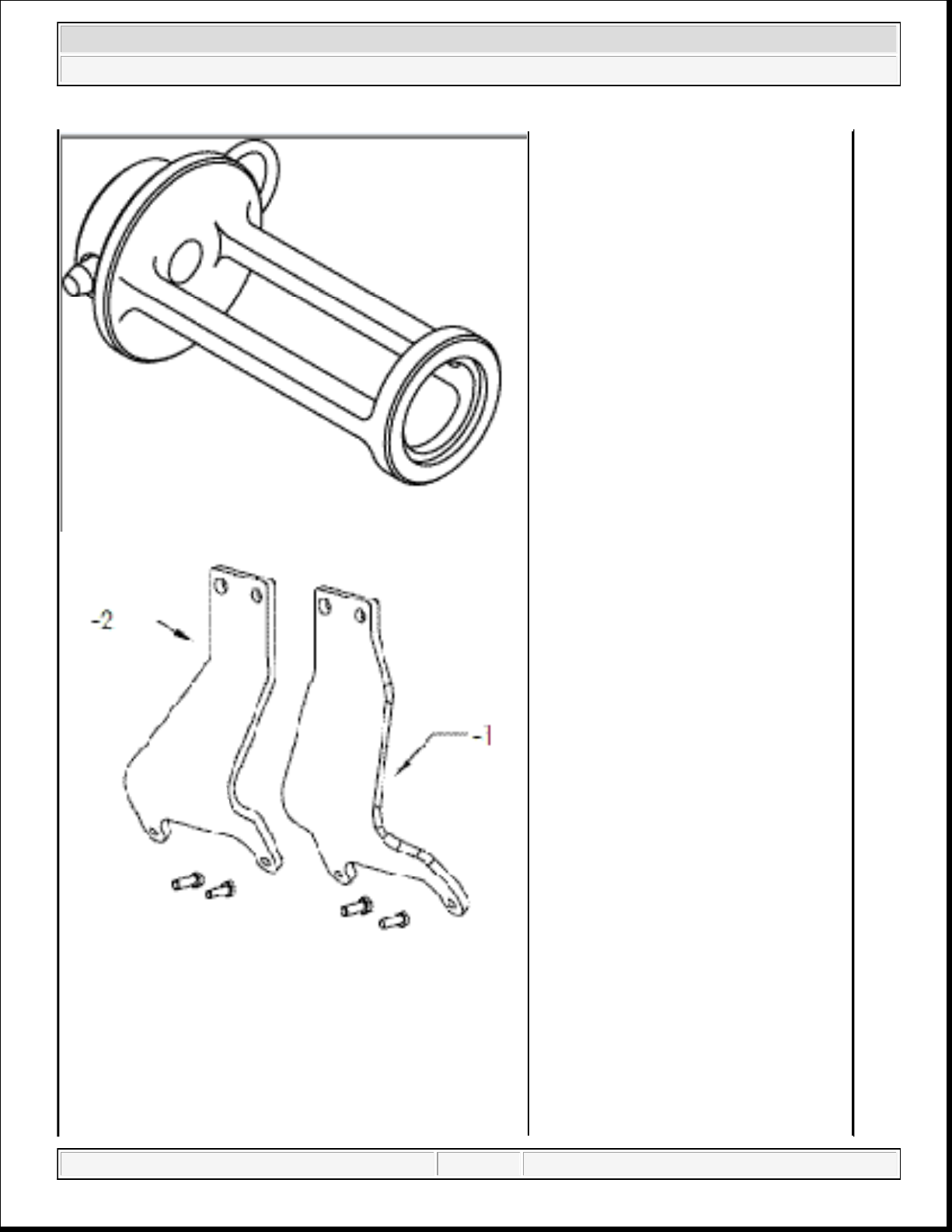
2014 RAM 1500 Laramie
2014 ENGINE 3.6L - Service Information - Ram Pickup
10224 - Adapter, Valve Spring
(Originally Shipped In Kit Number(s)
10223.)
10242-1 - Brackets, Engine Lifting, Left
Side
(Originally Shipped In Kit Number(s)
10223.)
domingo, 10 de octubre de 2021 04:48:07 p. m. Page 75 © 2011 Mitchell Repair Information Company, LLC.
Page 76
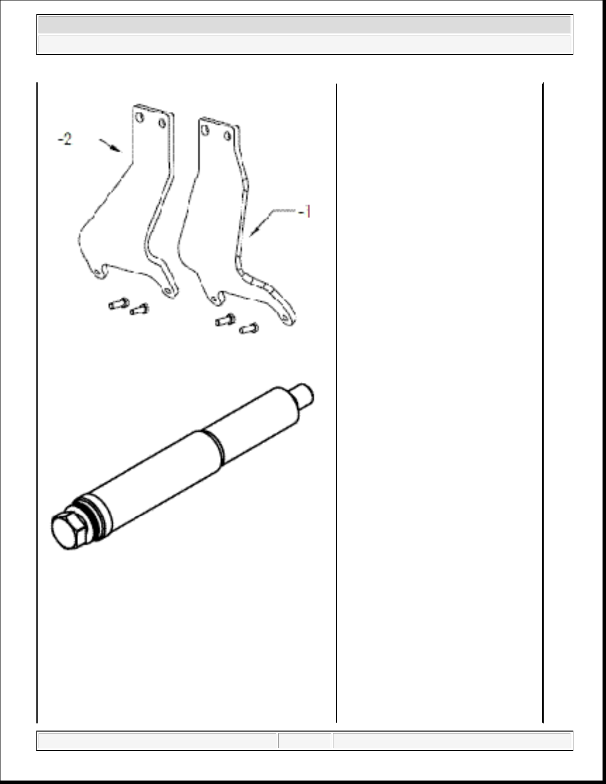
2014 RAM 1500 Laramie
2014 ENGINE 3.6L - Service Information - Ram Pickup
10242-2 - Brackets, Engine Lifting, Right
Side
(Originally Shipped In Kit Number(s)
10223.)
10255 - Installer, Spark Plug Tube
10256 - Installer, Cam Installer, Cam
Sensor/Spark Plug Tube Seal
(Originally Shipped In Kit Number(s)
domingo, 10 de octubre de 2021 04:48:07 p. m. Page 76 © 2011 Mitchell Repair Information Company, LLC.
Page 77
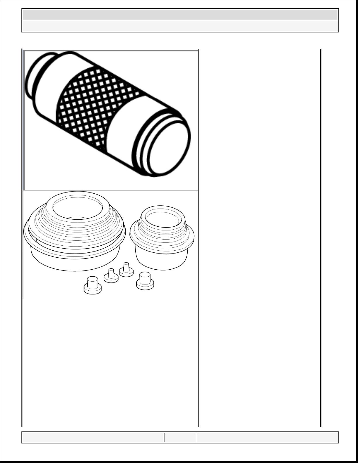
2014 RAM 1500 Laramie
2014 ENGINE 3.6L - Service Information - Ram Pickup
10256.)
10368 - Set, Universal Protective Cap
domingo, 10 de octubre de 2021 04:48:07 p. m. Page 77 © 2011 Mitchell Repair Information Company, LLC.
Page 78
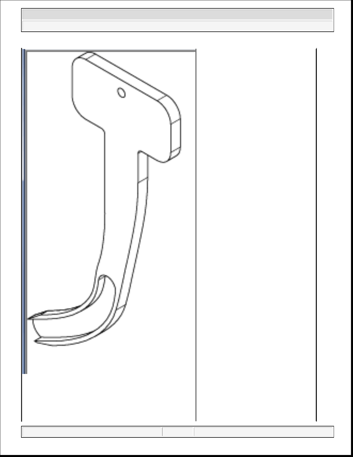
2014 RAM 1500 Laramie
2014 ENGINE 3.6L - Service Information - Ram Pickup
10369 - Holder, Timing Chain
domingo, 10 de octubre de 2021 04:48:07 p. m. Page 78 © 2011 Mitchell Repair Information Company, LLC.
Page 79
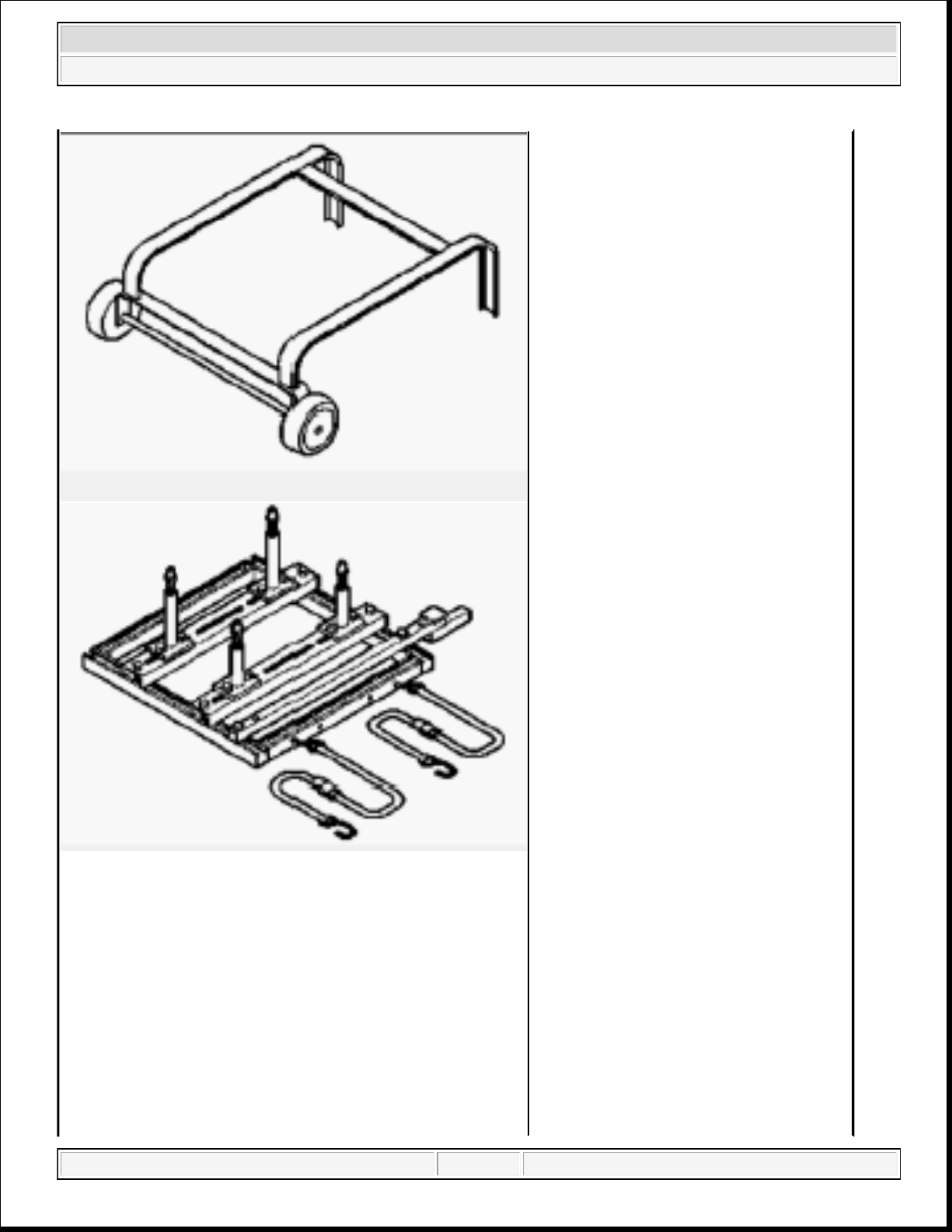
2014 RAM 1500 Laramie
2014 ENGINE 3.6L - Service Information - Ram Pickup
6135 - Dolly, Power Train
(Originally Shipped In Kit Number(s)
6784C.)
6710A - Cradle, Engine Support
(Originally Shipped In Kit Number(s)
6784, 6809.)
6848-3 - Adapter
(Originally Shipped In Kit Number(s)
domingo, 10 de octubre de 2021 04:48:07 p. m. Page 79 © 2011 Mitchell Repair Information Company, LLC.
Page 80
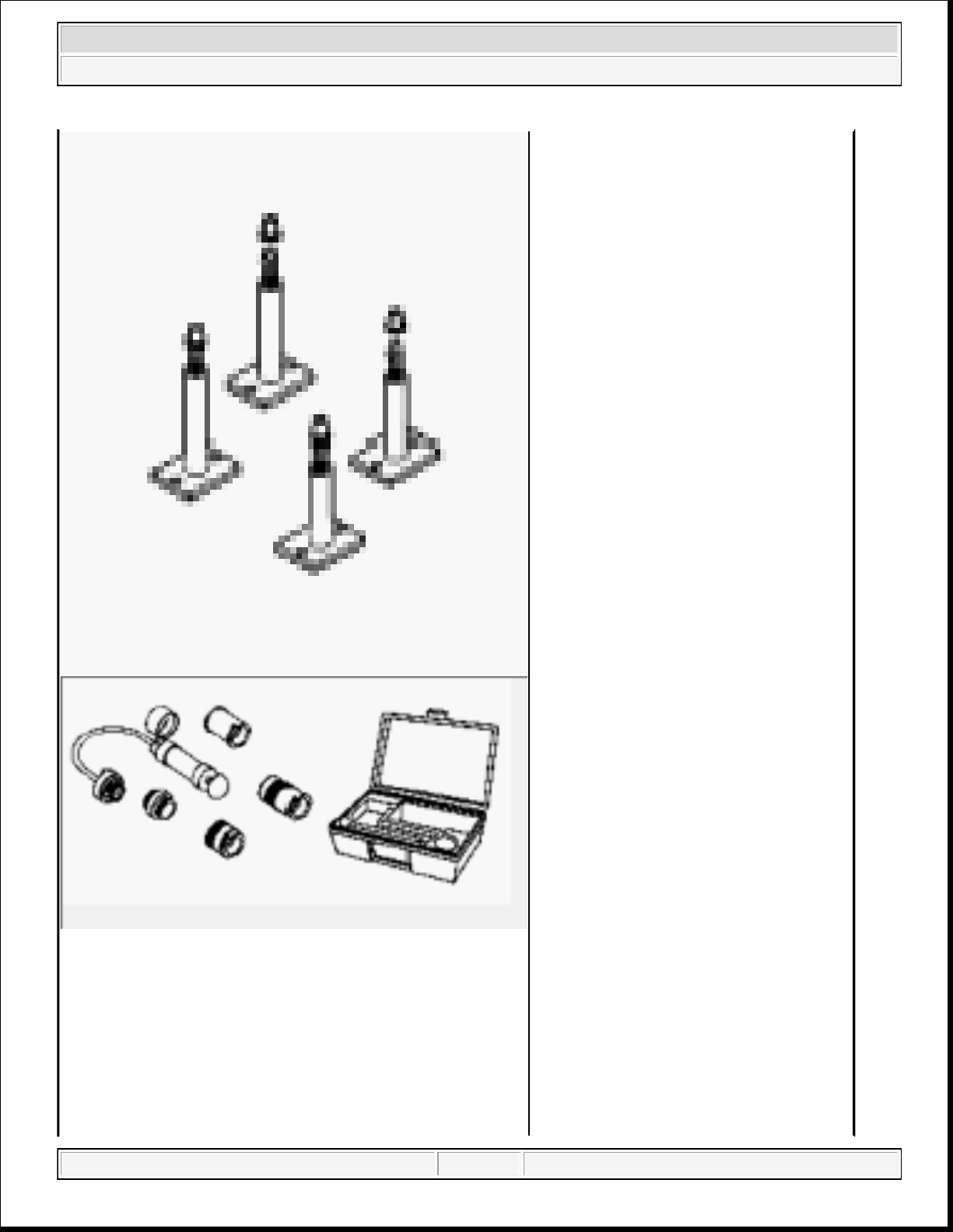
2014 RAM 1500 Laramie
2014 ENGINE 3.6L - Service Information - Ram Pickup
6880, 6881, 6882, 6883.)
7700-A - Tester, Cooling System
8189 - Guide Pins
(Originally Shipped In Kit Number(s)
8180, 8180CC, 8263, 8263CC.)
domingo, 10 de octubre de 2021 04:48:08 p. m. Page 80 © 2011 Mitchell Repair Information Company, LLC.
Page 81
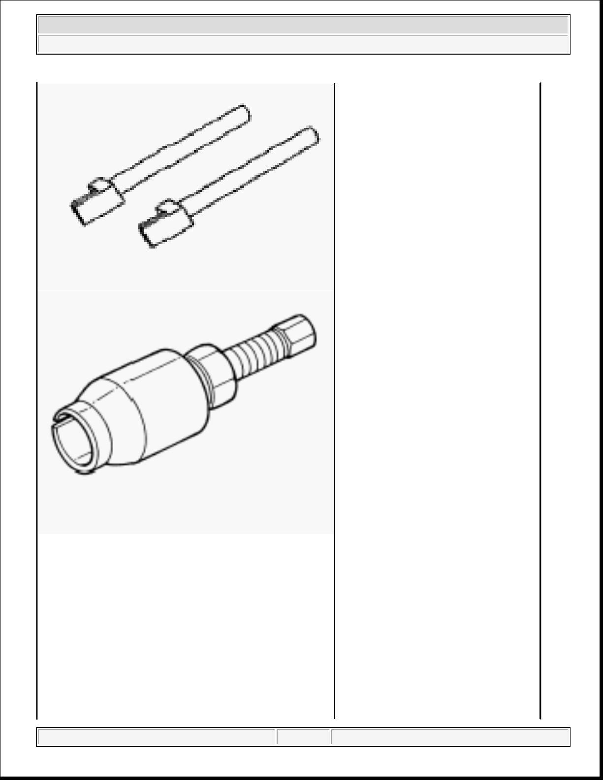
2014 RAM 1500 Laramie
2014 ENGINE 3.6L - Service Information - Ram Pickup
8511 - Remover, Seal
(Originally Shipped In Kit Number(s)
8283, 8283CC, 8527, 8527CC, 8575,
8575CC, 9975.)
8514 - Pins, Tensioner
(Originally Shipped In Kit Number(s)
8283, 8283CC, 8527, 8527CC, 8575,
8575CC, 9975.)
domingo, 10 de octubre de 2021 04:48:08 p. m. Page 81 © 2011 Mitchell Repair Information Company, LLC.
Page 82
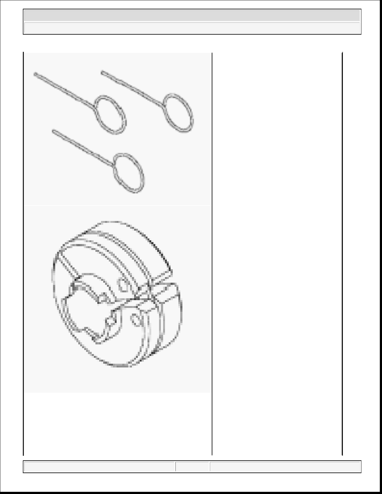
2014 RAM 1500 Laramie
2014 ENGINE 3.6L - Service Information - Ram Pickup
8875A - Disconnect, Transmission Cooler
Line
(Originally Shipped In Kit Number(s)
9202, 9328, 9328-CAN, 9329, 9516,
9575.)
C-119 - Cylinder Indicator
domingo, 10 de octubre de 2021 04:48:08 p. m. Page 82 © 2011 Mitchell Repair Information Company, LLC.
Page 83
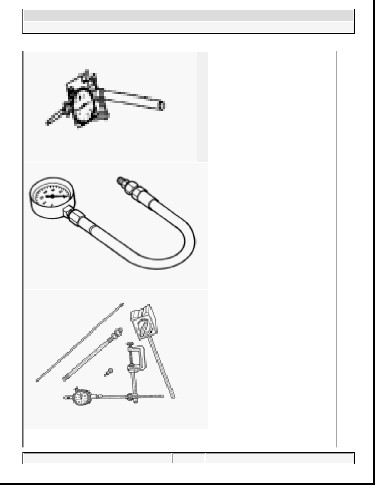
2014 RAM 1500 Laramie
2014 ENGINE 3.6L - Service Information - Ram Pickup
C-3292A - Gauge, Pressure
C-3339A - Set, Dial Indicator
(Originally Shipped In Kit Number(s)
9202.)
domingo, 10 de octubre de 2021 04:48:08 p. m. Page 83 © 2011 Mitchell Repair Information Company, LLC.
Page 84
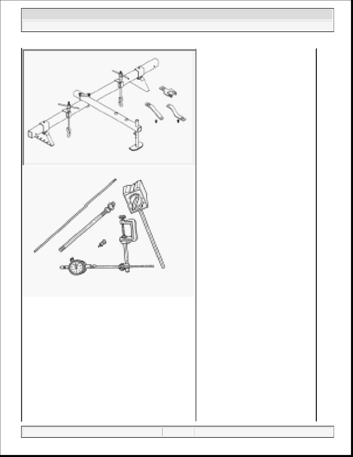
2014 RAM 1500 Laramie
2014 ENGINE 3.6L - Service Information - Ram Pickup
C-3422-D - Compressor, Valve Spring
C-3685-A - Bloc-Chek Kit
C-385 - Compressor, Piston
domingo, 10 de octubre de 2021 04:48:08 p. m. Page 84 © 2011 Mitchell Repair Information Company, LLC.
Page 85
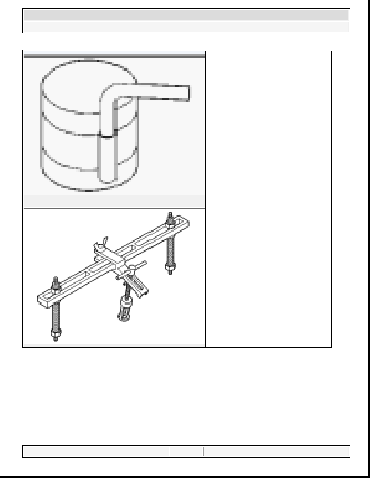
2014 RAM 1500 Laramie
2014 ENGINE 3.6L - Service Information - Ram Pickup
AIR INTAKE SYSTEM
AIR CLEANER
REMOVAL
3.6L
MD998772A - Compressor, Valve Spring
(Originally Shipped In Kit Number(s)
8678, 8853, 8854.)
domingo, 10 de octubre de 2021 04:48:08 p. m. Page 85 © 2011 Mitchell Repair Information Company, LLC.
Page 86
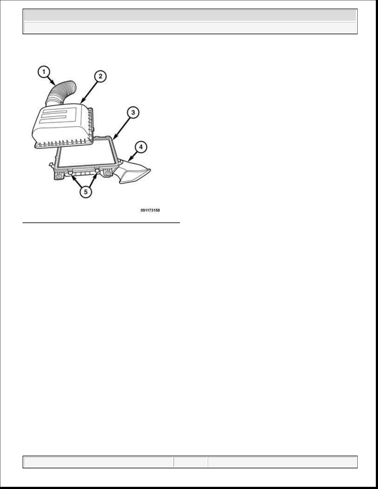
3.6L
2014 RAM 1500 Laramie
2014 ENGINE 3.6L - Service Information - Ram Pickup
Fig. 88: Removing/Installing Air Filter Box Cover
Courtesy of CHRYSLER GROUP, LLC
1. Release the air cleaner cover latches (5).
2. Remove the cover (2) from the lower housing assembly (4).
3. Remove the air filter element (3).
4. Clean the debris from the housing.
INSTALLATION
domingo, 10 de octubre de 2021 04:48:08 p. m. Page 86 © 2011 Mitchell Repair Information Company, LLC.
Page 87
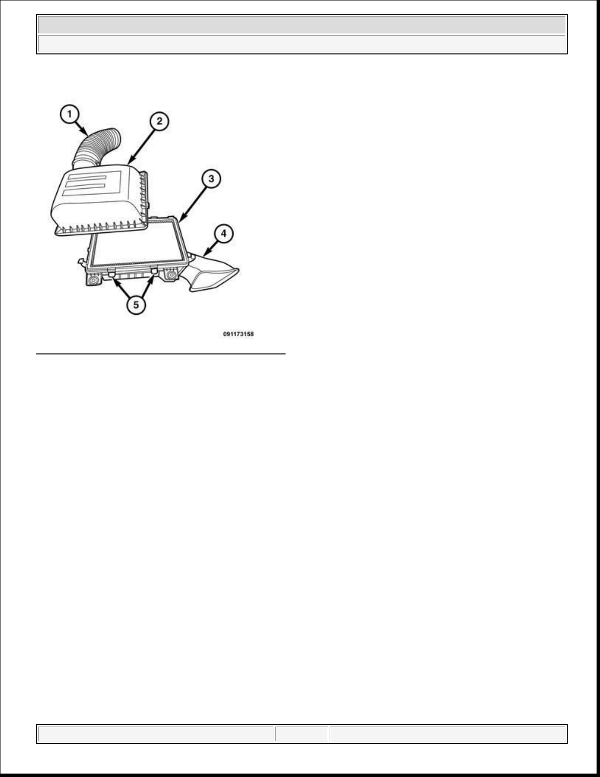
2014 RAM 1500 Laramie
2014 ENGINE 3.6L - Service Information - Ram Pickup
Fig. 89: Removing/Installing Air Filter Box Cover
Courtesy of CHRYSLER GROUP, LLC
1. Install air cleaner (3) into lower housing assembly (4).
2. Align the air filter cover (2) to the lower housing.
3. Secure the housing latches (5).
BODY, AIR CLEANER
REMOVAL
3.6L
domingo, 10 de octubre de 2021 04:48:08 p. m. Page 87 © 2011 Mitchell Repair Information Company, LLC.
Page 88
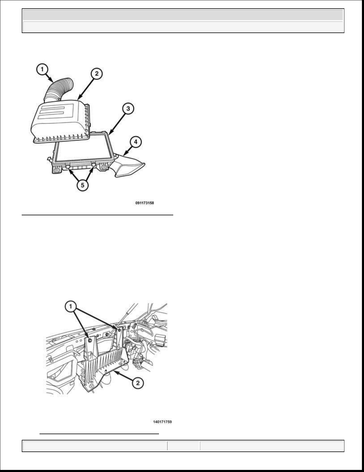
2014 RAM 1500 Laramie
2014 ENGINE 3.6L - Service Information - Ram Pickup
Fig. 90: Removing/Installing Air Filter Box Cover
Courtesy of CHRYSLER GROUP, LLC
1. Loosen the clamp at the air filter cover (2) and intake hose (1).
2. Separate the intake hose from the cover.
3. Remove the air filter cover from the lower housing assembly (4).
Fig. 91: Remove/Install Lower Housing
domingo, 10 de octubre de 2021 04:48:08 p. m. Page 88 © 2011 Mitchell Repair Information Company, LLC.
Page 89
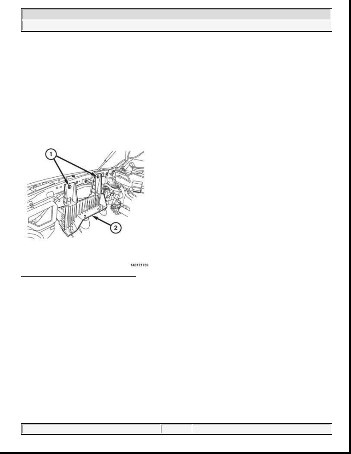
Courtesy of CHRYSLER GROUP, LLC
1.
If removed, install the air cleaner housing mount (2). Tighten the bolts (1) to 10 N.m (89 in. lbs.).
2014 RAM 1500 Laramie
2014 ENGINE 3.6L - Service Information - Ram Pickup
4. Remove the lower housing from the mount (2) by lifting upwards.
5. If required, remove the bolts (1) that secure the air filter mount to the inner fender.
INSTALLATION
3.6L
Fig. 92: Remove/Install Lower Housing
Courtesy of CHRYSLER GROUP, LLC
domingo, 10 de octubre de 2021 04:48:08 p. m. Page 89 © 2011 Mitchell Repair Information Company, LLC.
Page 90
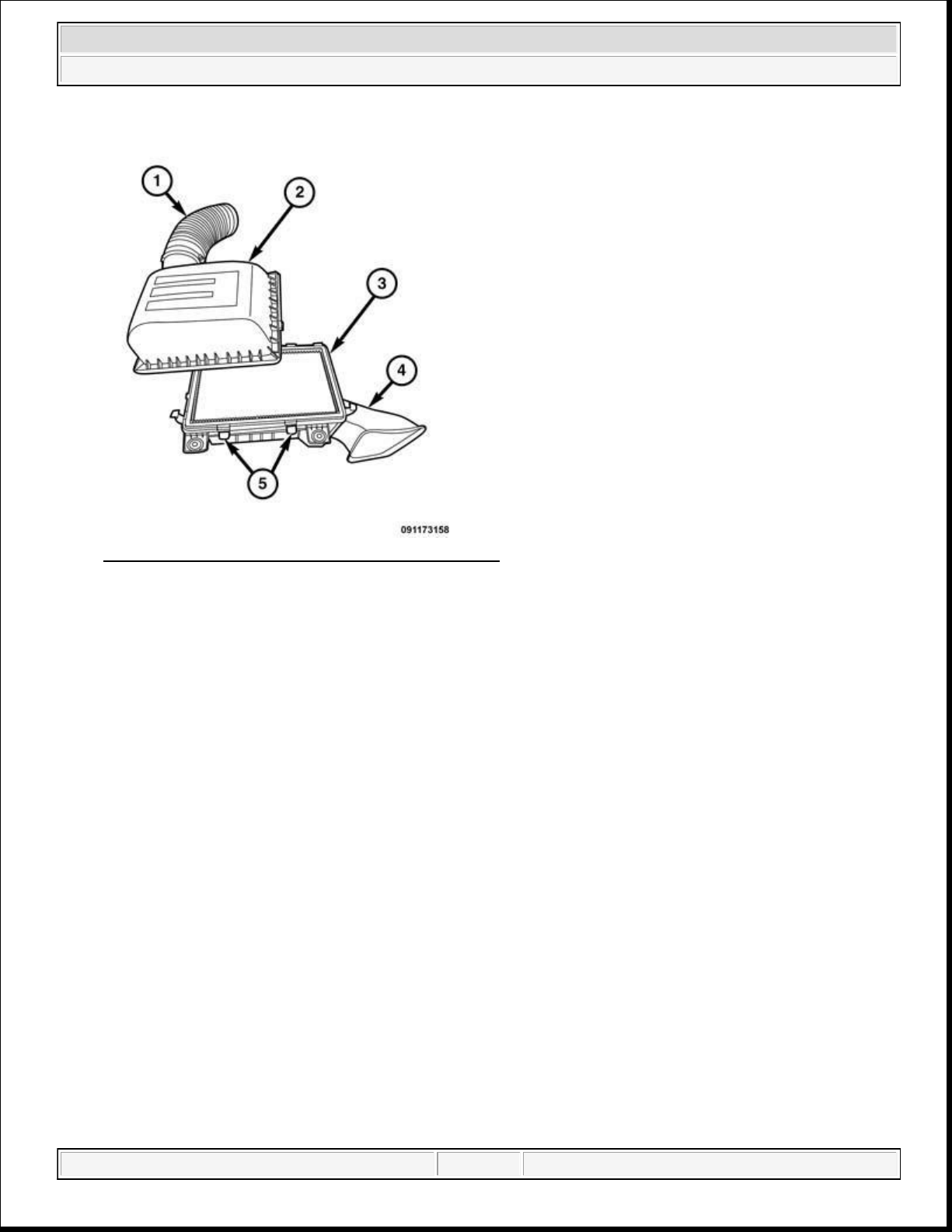
2014 RAM 1500 Laramie
2014 ENGINE 3.6L - Service Information - Ram Pickup
Fig. 93: Removing/Installing Air Filter Box Cover
Courtesy of CHRYSLER GROUP, LLC
2. Align the air cleaner housing (4) to the mounts and firmly press down.
3. Install the air cleaner cover (2).
4. Install the air intake hose (1) and hand tighten the clamp.
RESONATOR, AIR CLEANER
REMOVAL
REMOVAL
NOTE: The engine cover is bonded to the air intake assembly. Do not attempt to
separate them. The cover and intake must be removed as an assembly.
1. Disconnect and isolate the negative battery cable.
domingo, 10 de octubre de 2021 04:48:08 p. m. Page 90 © 2011 Mitchell Repair Information Company, LLC.
Page 91
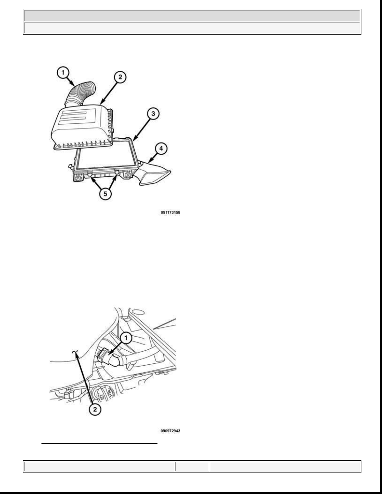
2014 RAM 1500 Laramie
2014 ENGINE 3.6L - Service Information - Ram Pickup
Fig. 94: Removing/Installing Air Filter Box Cover
Courtesy of CHRYSLER GROUP, LLC
2. Remove the air cleaner cover (2).
3. Loosen the clamp and remove the air inlet hose (1) from the resonator.
Fig. 95: Breather Tube & Resonator
Courtesy of CHRYSLER GROUP, LLC
domingo, 10 de octubre de 2021 04:48:08 p. m. Page 91 © 2011 Mitchell Repair Information Company, LLC.
Page 92
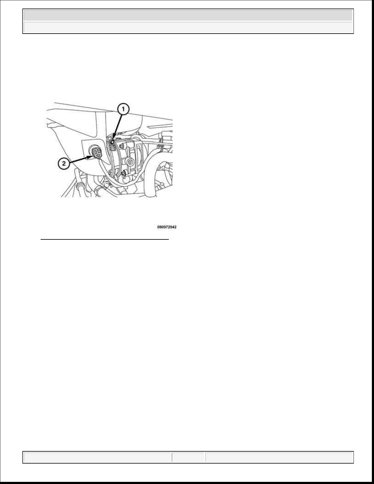
2014 RAM 1500 Laramie
2014 ENGINE 3.6L - Service Information - Ram Pickup
4. Remove the breather hose (1) from the rear of the resonator (2).
Fig. 96: IAT Sensor Electrical Connector
Courtesy of CHRYSLER GROUP, LLC
5. Disconnect the electrical connector (2) from the Inlet Air Temperature (IAT) sensor.
6. Loosen the clamp at the throttle body (1).
7. Pull the front of the resonator away from the throttle body while lifting from the rear of the resonator to
separate from the ball joint mount.
INSTALLATION
INSTALLATION
domingo, 10 de octubre de 2021 04:48:08 p. m. Page 92 © 2011 Mitchell Repair Information Company, LLC.
Page 93
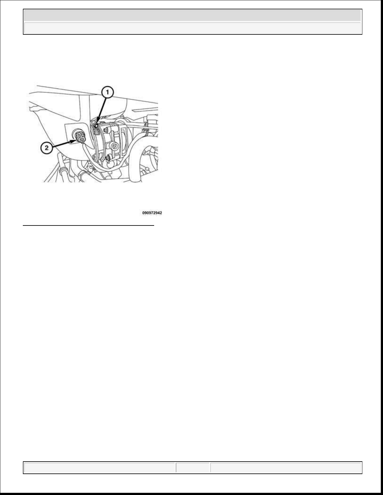
2014 RAM 1500 Laramie
2014 ENGINE 3.6L - Service Information - Ram Pickup
Fig. 97: IAT Sensor Electrical Connector
Courtesy of CHRYSLER GROUP, LLC
1. Lubricate the two rubber mount sockets on the resonator.
2. Install the resonator to the throttle body inlet. Push the resonator (1) down onto the two locating pins on
until the rubber mount sockets are fully seated.
3. Connect the electrical connector (2) to the Inlet Air Temperature (IAT) sensor.
4. Tighten the band clamp (1) to 4 N.m (35 in. lbs.).
domingo, 10 de octubre de 2021 04:48:08 p. m. Page 93 © 2011 Mitchell Repair Information Company, LLC.
Page 94
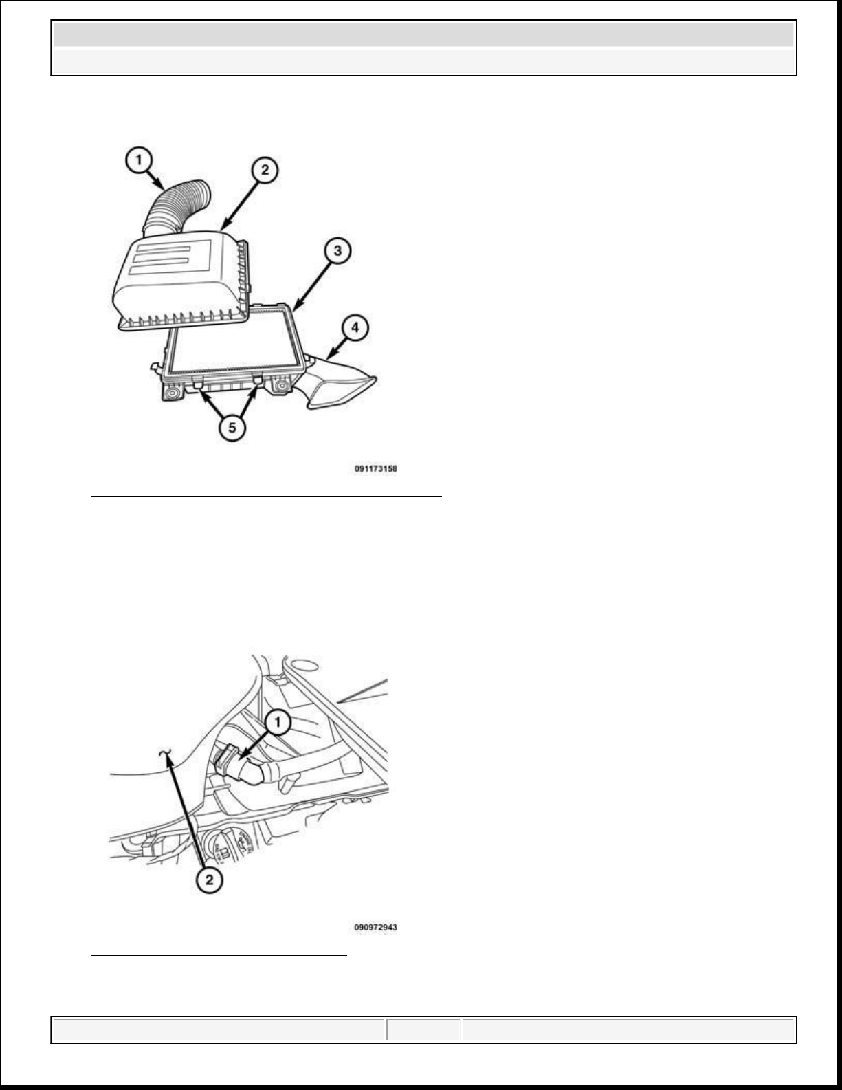
2014 RAM 1500 Laramie
2014 ENGINE 3.6L - Service Information - Ram Pickup
Fig. 98: Removing/Installing Air Filter Box Cover
Courtesy of CHRYSLER GROUP, LLC
5. Install the air inlet hose (1) to the resonator and hand tighten the clamp.
Fig. 99: Breather Tube & Resonator
Courtesy of CHRYSLER GROUP, LLC
domingo, 10 de octubre de 2021 04:48:08 p. m. Page 94 © 2011 Mitchell Repair Information Company, LLC.
Page 95
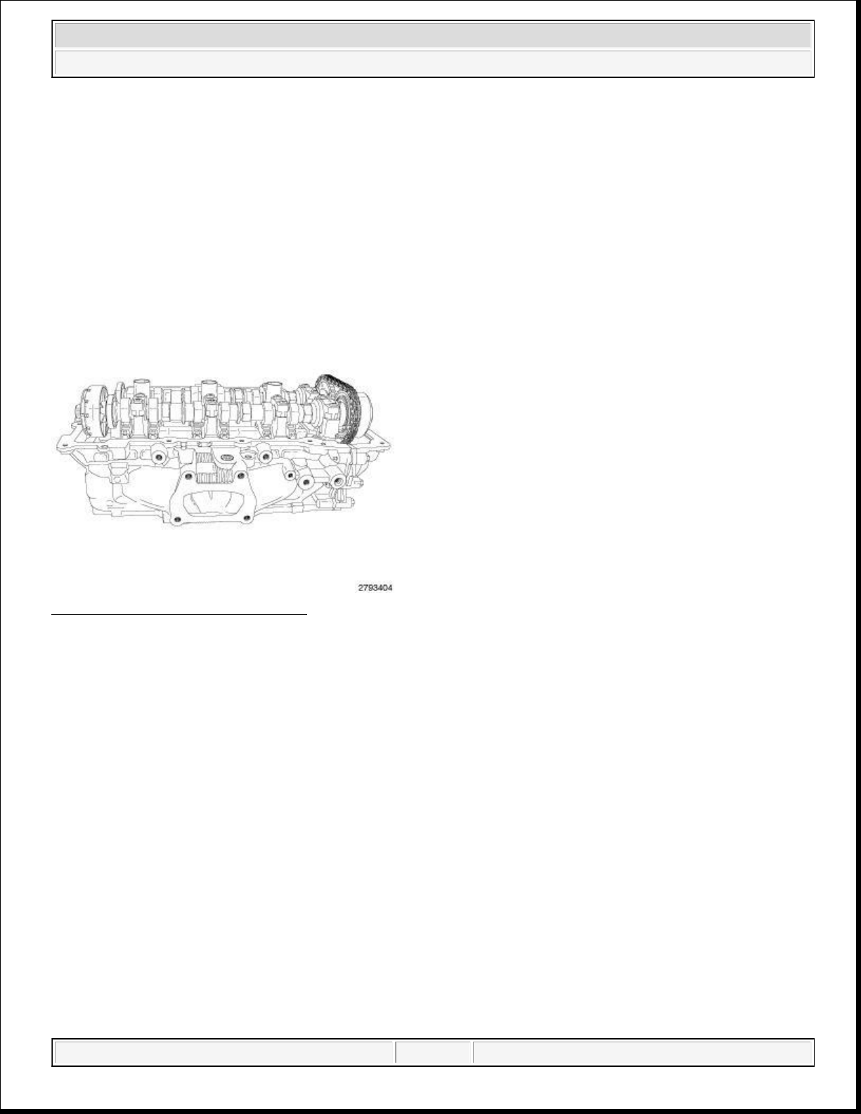
Engine misfiring
2014 RAM 1500 Laramie
2014 ENGINE 3.6L - Service Information - Ram Pickup
6. Install the breather hose (1) to the resonator (2).
7. Connect the negative battery cable and tighten nut to 5 N.m (45 in. lbs.).
CYLINDER HEAD
DESCRIPTION
DESCRIPTION
Fig. 100: Aluminum Cylinder Head
Courtesy of CHRYSLER GROUP, LLC
The aluminum cylinder heads are a unique design with left and right castings. The exhaust manifolds are
integrated into the cylinder heads. The cylinder head features four valves per cylinder with pressed in powdered
metal valve guides. The valve guides are not serviceable. The DOHC valvetrain uses roller rocker arms with
hydraulic lifters. The cylinder head's camshaft bearing caps are made of powdered metal and the location and
direction of each cap is marked on the side of the caps. The spark plug tubes are pressed into the cylinder heads
and sealed in place. The tubes are a thin wall design and caution must be taken when working in the spark plug
tube area.
DIAGNOSIS AND TESTING
CYLINDER HEAD GASKET
A cylinder head gasket leak can be located between adjacent cylinders or between a cylinder and the adjacent
water jacket.
Possible indications of the cylinder head gasket leaking between adjacent cylinders are:
Loss of engine power
domingo, 10 de octubre de 2021 04:48:08 p. m. Page 95 © 2011 Mitchell Repair Information Company, LLC.
Page 96
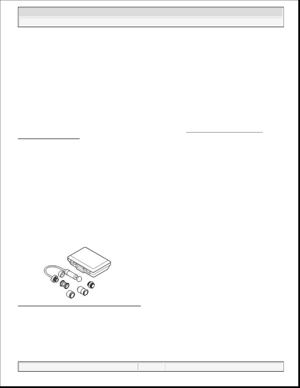
2014 RAM 1500 Laramie
2014 ENGINE 3.6L - Service Information - Ram Pickup
Poor fuel economy
Possible indications of the cylinder head gasket leaking between a cylinder and an adjacent water jacket are:
Engine overheating
Loss of coolant
Excessive steam (white smoke) emitting from exhaust
Coolant foaming
CYLINDER-TO-CYLINDER LEAKAGE TEST
To determine if an engine cylinder head gasket is leaking between the cylinders located next to each other,
follow the procedures in Cylinder Compression Pressure Test. Refer to CYLINDER COMPRESSION
PRESSURE LEAKAGE. An engine cylinder head gasket leaking between the cylinders will result in
approximately a 50 - 70% reduction in compression pressure.
CYLINDER-TO-WATER JACKET LEAKAGE TEST
WARNING: USE EXTREME CAUTION WHEN THE ENGINE IS OPERATING WITH
COOLANT PRESSURE CAP REMOVED.
VISUAL TEST METHOD
With the engine cool, remove the coolant pressure cap. Start the engine and allow it to warm up until thermostat
opens.
If a large combustion/compression pressure leak exists, bubbles will be visible in the coolant.
COOLING SYSTEM TESTER METHOD
Fig. 101: Cooling System Pressure Tester - 7700a
Courtesy of CHRYSLER GROUP, LLC
WARNING: WITH THE COOLING SYSTEM TESTER IN PLACE, PRESSURE WILL
BUILD UP FAST. EXCESSIVE PRESSURE BUILT UP BY CONTINUOUS
ENGINE OPERATION MUST BE RELEASED TO A SAFE PRESSURE
POINT. NEVER PERMIT THE PRESSURE TO EXCEED 138 kPa (20 psi).
domingo, 10 de octubre de 2021 04:48:08 p. m. Page 96 © 2011 Mitchell Repair Information Company, LLC.
Page 97
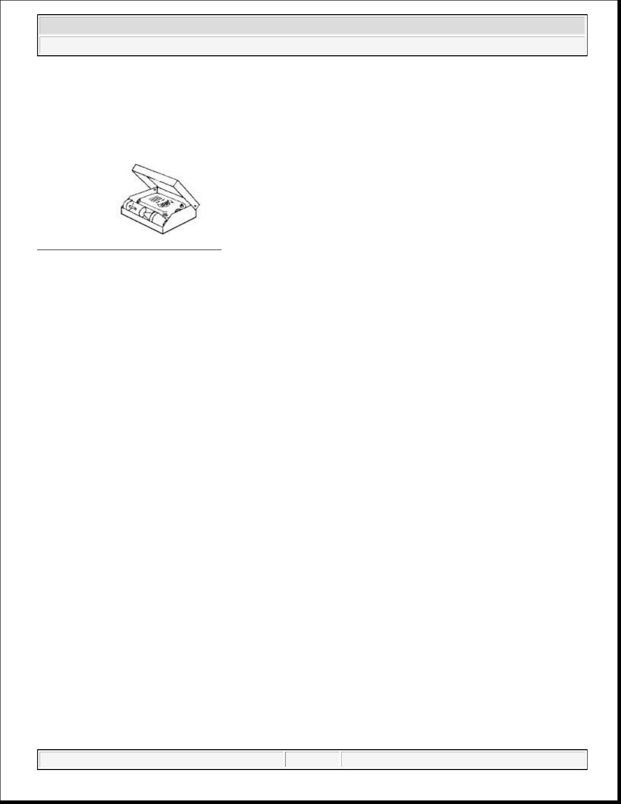
Install Cooling System Tester (special tool #7700
-
A, Tester, Cooling System) or equivalent to pressure cap
2014 RAM 1500 Laramie
2014 ENGINE 3.6L - Service Information - Ram Pickup
neck. Start the engine and observe the tester's pressure gauge. If gauge pulsates with every power stroke of a
cylinder a combustion pressure leak is evident.
CHEMICAL TEST METHOD
Fig. 102: Bloc-Chek-Kit - C-3685-A
Courtesy of CHRYSLER GROUP, LLC
Combustion leaks into the cooling system can also be checked by using a (special tool #C-3685-A, Bloc-Chek
Kit) or equivalent. Perform the test following the procedures supplied with the tool kit.
HYDRAULIC LASH ADJUSTER
A tappet-like noise may be produced from several items. Check the following items.
1. Engine oil level too high or too low. This may cause aerated oil to enter the adjusters and cause them to
be spongy.
2. Insufficient running time after rebuilding cylinder head. Low speed running up to 1 hour may be required.
3. Turn engine off and let set for a few minutes before restarting. Repeat this several times after engine has
reached normal operating temperature.
4. Low oil pressure.
5. The oil passage in cylinder head gasket or the oil passage to the cylinder head is plugged with debris.
6. Air ingested into oil due to broken or cracked oil pump pick up.
7. Worn valve guides.
8. Rocker arm ears contacting valve spring retainer.
9. Rocker arm loose, adjuster stuck or at maximum extension and still leaves lash in the system.
10. Oil leak or excessive cam bore wear in cylinder head.
11. Faulty lash adjuster.
Check lash adjusters for "sponginess" while installed in cylinder head and cam on camshaft at base
circle. Depress part of rocker arm over adjuster. Normal adjusters should feel firm when pressed
quickly. When pressed very slowly, lash adjusters should collapse.
Remove suspected lash adjusters, and replace.
Before installation, make sure adjusters are full of oil. This can be verified by little plunger travel
when lash adjuster is depressed quickly.
REMOVAL
LEFT
domingo, 10 de octubre de 2021 04:48:08 p. m. Page 97 © 2011 Mitchell Repair Information Company, LLC.
Page 98
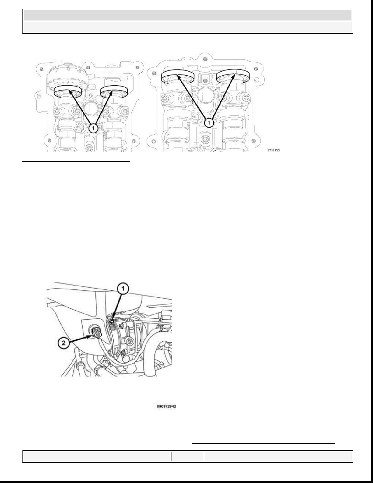
2014 ENGINE 3.6L - Service Information - Ram Pickup
Fig. 103: Magnetic Timing Wheels
Courtesy of CHRYSLER GROUP, LLC
CAUTION: The magnetic timing wheels (1) must not come in contact with magnets
(pickup tools, trays, etc.) or any other strong magnetic field. This will
destroy the timing wheels ability to correctly relay camshaft position to the
camshaft position sensor.
2014 RAM 1500 Laramie
1. Perform the fuel pressure release procedure. Refer to FUEL SYSTEM PRESSURE RELEASE .
2. Disconnect and isolate the negative battery cable.
Fig. 104: IAT Sensor Electrical Connector
Courtesy of CHRYSLER GROUP, LLC
3. Remove the air intake resonator assembly. Refer to RESONATOR, AIR CLEANER, REMOVAL.
domingo, 10 de octubre de 2021 04:48:08 p. m. Page 98 © 2011 Mitchell Repair Information Company, LLC.
Page 99
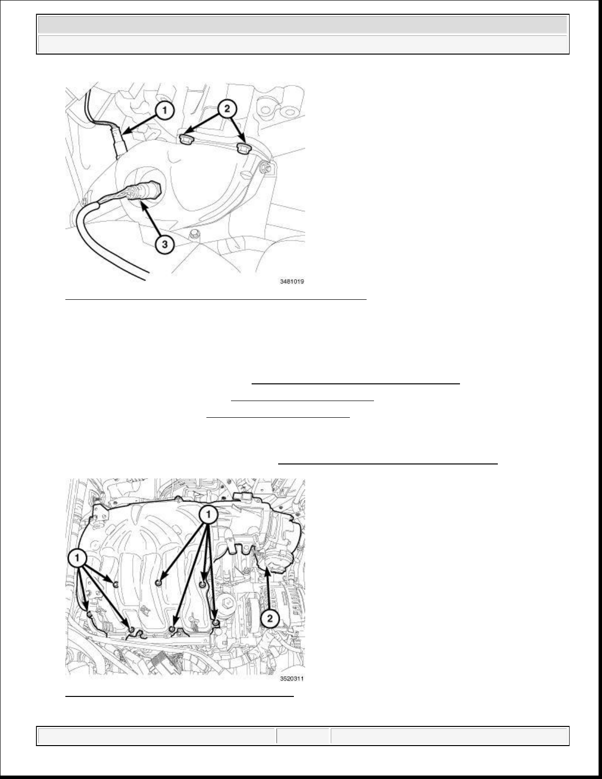
2014 RAM 1500 Laramie
2014 ENGINE 3.6L - Service Information - Ram Pickup
Fig. 105: Upstream & Downstream Oxygen Sensors & Bolts
Courtesy of CHRYSLER GROUP, LLC
NOTE: Right catalytic converter shown in illustration, left catalytic converter
similar.
4. Raise and support the vehicle. Refer to HOISTING, STANDARD PROCEDURE .
5. Drain the cooling system. Refer to STANDARD PROCEDURE .
6. Drain the engine oil. Refer to STANDARD PROCEDURE .
7. Disconnect the left upstream (3) and downstream (1) oxygen sensor connectors from the main wire
harness.
8. Remove the left catalytic converter. Refer to CONVERTER, CATALYTIC, REMOVAL .
Fig. 106: Upper Intake Manifold & Fasteners
Courtesy of CHRYSLER GROUP, LLC
domingo, 10 de octubre de 2021 04:48:08 p. m. Page 99 © 2011 Mitchell Repair Information Company, LLC.
Page 100
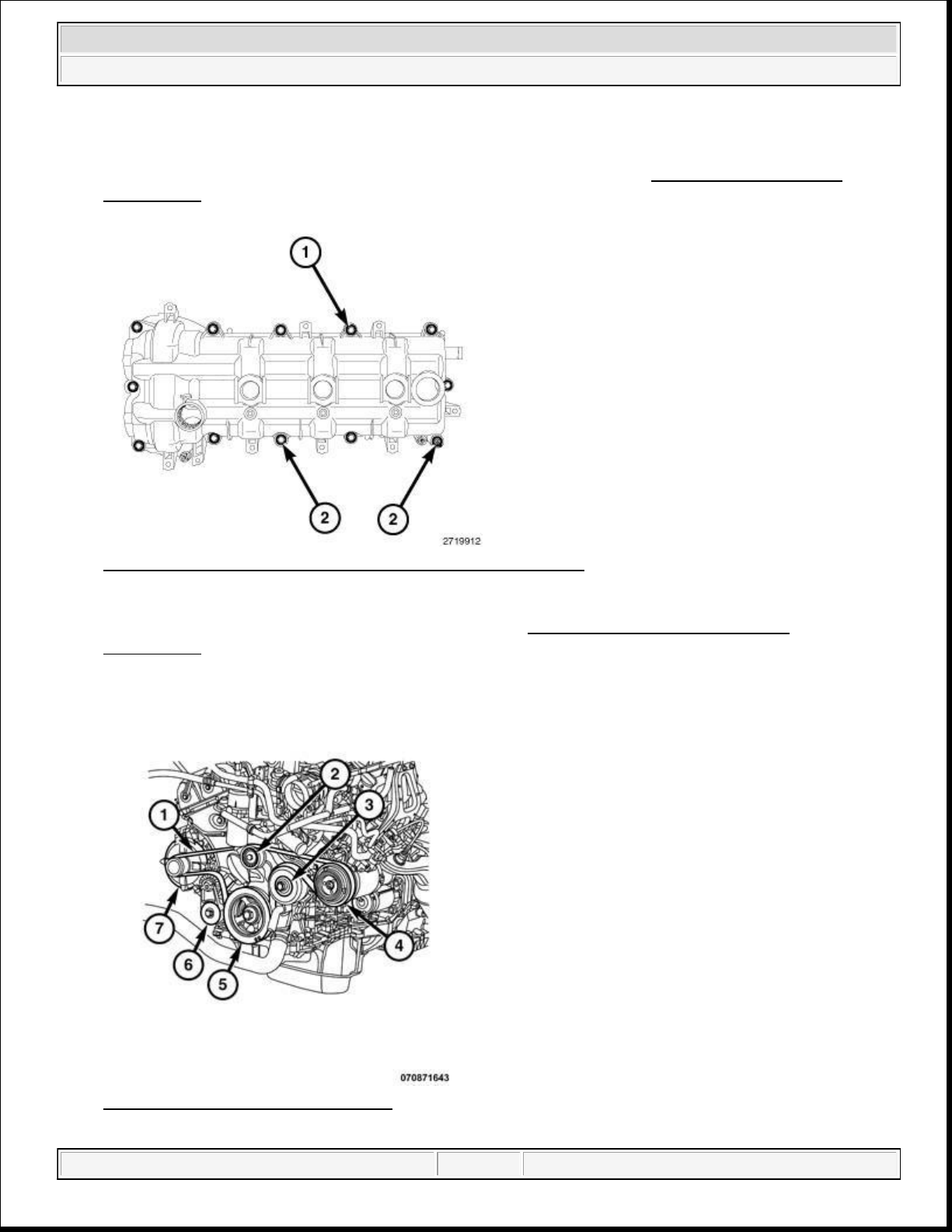
Courtesy of CHRYSLER GROUP, LLC
2014 RAM 1500 Laramie
2014 ENGINE 3.6L - Service Information - Ram Pickup
9. Lower the vehicle.
10. Remove the upper and lower intake manifolds (2) and insulator. Refer to MANIFOLD, INTAKE,
REMOVAL .
Fig. 107: Cylinder Head Cover Mounting Bolts & Stud Bolts
Courtesy of CHRYSLER GROUP, LLC
11. Remove the right and left cylinder head covers. Refer to COVER(S), CYLINDER HEAD,
REMOVAL .
Fig. 108: Belt Routing (3.6L Engine)
domingo, 10 de octubre de 2021 04:48:08 p. m. Page 100 © 2011 Mitchell Repair Information Company, LLC.
 Loading...