

Page 1

2 0 1 1
O W N E R ’ S M A N U A L
Ram Truck
D IE S E L
Page 2

VEHICLES SOLD IN CANADA
With respect to any Vehicles Sold in Canada, the name
Chrysler Group LLC shall be deemed to be deleted and
the name Chrysler Canada Inc. used in substitution
therefore.
DRIVING AND ALCOHOL
Drunken driving is one of the most frequent causes of
accidents.
Your driving ability can be seriously impaired with blood
alcohol levels far below the legal minimum. If you are
drinking, don’t drive. Ride with a designated non-drinking
driver, call a cab, a friend, or use public transportation.
WARNING!
Driving after drinking can lead to an accident. Your
perceptions are less sharp, your reflexes are slower,
and your judgment is impaired when you have been
drinking. Never drink and then drive.
This manual illustrates and describes the operation of
features and equipment that are either standard or optional on this vehicle. This manual may also include a
description of features and equipment that are no longer
available or were not ordered on this vehicle. Please
disregard any features and equipment described in this
manual that are not on this vehicle.
Chrysler Group LLC reserves the right to make changes
in design and specifications, and/or make additions to or
improvements to its products without imposing any
obligation upon itself to install them on products previously manufactured.
Copyright © 2010 Chrysler Group LLC
Page 3

SECTION PAGE
1
INTRODUCTION
2
THINGS TO KNOW BEFORE STARTING YOUR VEHICLE
3
UNDERSTANDING YOUR INSTRUMENT PANEL
4
STARTING AND OPERATING
5
WHAT TO DO IN EMERGENCIES
6
MAINTAINING YOUR VEHICLE
7
MAINTENANCE SCHEDULES
8
INDEX
...................................................................163
TABLE OF CONTENTS
............................................................3
..............................5
................................... 11
.................................................43
.............................................. 91
...............................................97
.................................................137
1
2
3
4
5
6
7
8
Page 4

Page 5

INTRODUCTION
CONTENTS
䡵 A Message From Chrysler Group LLC ......... 4
1
Page 6

4 INTRODUCTION
A MESSAGE FROM CHRYSLER GROUP LLC
Chrysler Group LLC and Cummins威 welcome you as a
Cummins威 turbocharged diesel-powered truck owner.
Your diesel truck will sound, feel, drive, and operate
differently from a gasoline-powered truck. It is important
that you read and understand this manual.
Almost 100% of the heavy duty trucks in the United
States and Canada are diesel-powered because of the fuel
economy, rugged durability, and high torque which permits pulling heavy loads. Cummins威 engines power well
over half of these trucks. Now this same technology and
proven performance is yours in your truck equipped
with the Cummins威 turbocharged diesel engine.
You may find that some of the starting, operating, and
maintenance procedures are different. However, they are
simple to follow and careful adherence to them will
ensure that you take full advantage of the features of this
engine.
NOTE: Some aftermarket products may cause severe
engine/transmission and/or exhaust system damage.
Your vehicle’s Powertrain Control Systems can detect
and store information about vehicle modifications that
increase horsepower and torque output such as whether
or not performance-enhancing powertrain components,
commonly referred to as downloaders, power boxes, or
performance chips have been used.
This information cannot be erased and will stay in the
system’s memory even if the modification is removed.
This information can be retrieved by Chrysler Group
LLC, and service and repair facilities, when servicing
your vehicle. This information may be used to determine
if repair will be covered by warranty.
There is a probability that the use of a “performance
chip” will prohibit the engine from starting. In this
instance, the vehicle will need to be serviced by a
authorized dealer in order to return the vehicle to it’s
factory settings.
Page 7

THINGS TO KNOW BEFORE STARTING YOUR VEHICLE
CONTENTS
䡵 Steering Wheel Lock — If Equipped ..........6
▫ To Manually Lock The Steering Wheel ....... 6
▫ To Release The Steering Wheel Lock .........6
2
䡵 Remote Starting System — If Equipped ........ 6
▫ How To Use Remote Start ................ 7
䡵 Engine Break-In Recommendations .......... 10
Page 8

6 THINGS TO KNOW BEFORE STARTING YOUR VEHICLE
STEERING WHEEL LOCK — IF EQUIPPED
Your vehicle may be equipped with a passive steering
wheel lock. This lock prevents steering the vehicle without the key fob. If the steering wheel is moved approximately a half turn in either direction and the key fob is
not in the ignition switch, the steering wheel will lock.
To Manually Lock The Steering Wheel
With the engine running, turn the steering wheel upside
down, turn off the engine and remove the key fob. Turn
the steering wheel slightly in either direction until the
lock engages.
To Release The Steering Wheel Lock
Insert the key fob into the ignition switch and start the
engine. If the key fob is difficult to turn, move the wheel
slightly to the right or left to disengage the lock.
NOTE: If you turned the wheel to the right to engage
the lock, you must turn the wheel slightly to the right to
disengage it. If you turned the wheel to the left to engage
the lock, turn the wheel slightly to the left to disengage it.
REMOTE STARTING SYSTEM — IF EQUIPPED
This system uses the Remote Keyless Entry
(RKE) transmitter to start the engine conveniently from outside the vehicle while still
maintaining security. The system has a range of
approximately 328 ft (100 m).
NOTE:
•
The vehicle must be equipped with an automatic
transmission to be equipped with Remote Start.
•
The remote start system will wait for the “Wait To Start
Light” to extinguish before cranking the engine. This
allows time for the intake heater to pre-heat the
incoming air, and is normal operation in cold weather.
Refer to “Electronic Vehicle Information Center/EVIC
Warning Lights” in “Understanding Your Instrument
Panel” for further information on and “Wait To Start
Light” and pre-heat cycle.
Page 9
How To Use Remote Start
All of the following conditions must be met before the
engine will remote start:
•
Shift lever in PARK
•
Doors closed
•
Hood closed
•
HAZARD switch off
•
BRAKE switch inactive (brake pedal not pressed)
•
Ignition key removed from ignition switch
•
Battery at an acceptable charge level
•
RKE PANIC button not pressed
•
Fuel meets minimum requirement
•
Water In Fuel Indicator Light is not illuminated
•
Wait To Start Light is not illuminated
THINGS TO KNOW BEFORE STARTING YOUR VEHICLE 7
WARNING!
•
Do not start or run an engine in a closed garage or
confined area. Exhaust gas contains Carbon Monoxide (CO) which is odorless and colorless. Carbon Monoxide is poisonous and can cause serious
injury or death when inhaled.
•
Keep Remote Keyless Entry (RKE) transmitters
away from children. Operation of the Remote Start
System, windows, door locks or other controls
could cause serious injury or death.
Remote Start Abort Message On Electronic Vehicle
Information Center (EVIC) – If Equipped
The following messages will display in the EVIC if the
vehicle fails to remote start or exits remote start prematurely:
•
Remote Start Aborted - Door Ajar
2
Page 10

8 THINGS TO KNOW BEFORE STARTING YOUR VEHICLE
•
Remote Start Aborted - Hood Ajar
•
Remote Start Aborted - Fuel Low
•
Remote Start Aborted - System Fault
The EVIC message stays active until the ignition is turned
to the ON/RUN position.
To Enter Remote Start Mode
Press and release the REMOTE START button
on the RKE transmitter twice, within five seconds. The parking lights will flash and the horn
will chirp twice (if programmed). In cold ambient temperature conditions, the diesel vehicle may
delay crank up to 30 seconds for the glow plugs or grid
heater. Once the vehicle has started, the engine will run
for 15 minutes.
NOTE:
•
The park lamps will turn on and remain on during
Remote Start mode.
•
For security, power window and power sunroof operation (if equipped) are disabled when the vehicle is
in the Remote Start mode.
•
The engine can be started two consecutive times (two
15-minute cycles) with the RKE transmitter. However,
the ignition switch must be cycled to the ON position
before you can repeat the start sequence for a third
cycle.
To Exit Remote Start Mode Without Driving The
Vehicle
Press and release the REMOTE START button one time or
allow the engine to run for the entire 15-minute cycle.
NOTE: To avoid unintentional shut downs, the system
will disable the one time press of the REMOTE START
button for two seconds after receiving a valid Remote
Start request.
Page 11

To Exit Remote Start Mode And Drive The Vehicle
Before the end of the 15-minute cycle, press and release
the UNLOCK button on the RKE transmitter to unlock
the doors and disarm the Vehicle Security Alarm System
(if equipped). Insert the Key Fob into the ignition switch
and turn the switch to the ON/RUN position.
NOTE:
•
The ignition switch must be in the ON/RUN position
in order to drive the vehicle.
•
For vehicles equipped with the Electronic Vehicle
Information Center (EVIC), the message “Insert Key/
Turn To On” will flash in the EVIC until you insert the
Key Fob into the ignition swich. Once inserted, the
message “Turn To On” will flash in the EVIC until you
turn the ignition switch to the ON/RUN position.
THINGS TO KNOW BEFORE STARTING YOUR VEHICLE 9
Remote Start Comfort Systems – If Equipped
When remote start is activated, the heated steering
wheel, and driver heated seat features will automatically
turn on in cold weather. In warm weather, the driver
vented seat feature will automatically turn on when the
remote start is activated. These features will stay on
through the duration of remote start or until the ignition
switch is turned to the ON position.
The Remote Start Comfort System can be activated and
deactivated through the Electronic Vehicle Information
Center (EVIC). For more information on Remote Start
Comfort System operation refer to “Electronic Vehicle
Information Center (EVIC)/Customer-Programmable
Features (System Setup)” in “Understanding Your Instrument Panel”.
2
Page 12

10 THINGS TO KNOW BEFORE STARTING YOUR VEHICLE
ENGINE BREAK-IN RECOMMENDATIONS
The Cummins威 turbocharged diesel engine does not
require a break-in period due to its construction. Normal
operation is allowed, providing the following recommendations are followed:
•
Warm up the engine before placing it under load.
•
Do not operate the engine at idle for prolonged
periods.
•
Use the appropriate transmission gear to prevent
engine lugging.
•
Observe vehicle oil pressure and temperature indicators.
•
Check the coolant and oil levels frequently.
•
Vary throttle position at highway speeds when carrying or towing significant weight.
NOTE: Light duty operation such as light trailer towing
or no load operation will extend the time before the
engine is at full efficiency. Reduced fuel economy and
power may be seen at this time.
For additional vehicle break-in requirements, refer to
“Trailer Towing” in “Starting and Operating” of the
Owners Manual.
Because of the construction of the Cummins威 turbocharged diesel engine, engine run-in is enhanced by
loaded operating conditions which allow the engine
parts to achieve final finish and fit during the first
6,000 miles (10 000 km).
Page 13

UNDERSTANDING YOUR INSTRUMENT PANEL
CONTENTS
䡵 Instrument Cluster ..................... 12
䡵 Instrument Cluster Description ............. 13
䡵 Electronic Vehicle Information Center (EVIC) . . . 22
▫ EVIC Displays ....................... 25
▫ Distance To Empty (DTE) ............... 32
▫ Trip Functions ....................... 32
3
▫ Vehicle Information (Customer Information
Features) ........................... 33
▫ Compass / Temperature Display .......... 34
▫ Customer-Programmable Features (System
Setup) ............................. 37
Page 14

12 UNDERSTANDING YOUR INSTRUMENT PANEL
INSTRUMENT CLUSTER
Page 15
INSTRUMENT CLUSTER DESCRIPTION
1. Tachometer
The tachometer indicates engine speed in revolutions per
minute.
CAUTION!
Do not operate the engine with the tachometer
pointer at high RPM for extended periods. Engine
damage may occur.
2. Turn Signal Indicator Light
The arrow will flash with the exterior turn signal
when the turn signal lever is operated.
UNDERSTANDING YOUR INSTRUMENT PANEL 13
3. Fuel Gauge
Shows level of fuel in tank when ignition switch is in the
ON position.
4. Temperature Gauge
The temperature gauge shows engine coolant temperature. Any reading within the normal range indicates that
the engine cooling system is operating satisfactorily.
The gauge pointer will likely indicate a higher temperature when driving in hot weather, up mountain grades,
or when towing a trailer. It should not be allowed to
exceed the upper limits of the normal operating range.
WARNING!
3
NOTE:
•
A continuous chime will sound if the vehicle is driven
more than 1 mile (1.6 km) with either turn signal on.
•
Check for an inoperative outside light bulb if either
indicator flashes at a rapid rate.
A hot engine cooling system is dangerous. You or
others could be badly burned by steam or boiling
coolant. You may want to call an authorized dealership for service if your vehicle overheats.
Page 16

14 UNDERSTANDING YOUR INSTRUMENT PANEL
5. Speedometer
The speedometer shows the vehicle speed in miles per
hour and/or kilometers per hour (MPH/km/h).
6. 4LOW Indicator Light – If Equipped
This light alerts the driver that the vehicle is in
the four-wheel drive LOW mode. The front and
rear driveshafts are mechanically locked to-
gether forcing the front and rear wheels to
rotate at the same speed. Low range provides a greater
gear reduction ratio to provide increased torque at the
wheels.
For vehicles equipped with a premium cluster this indicator will display in the Electronic Vehicle Information
Center (EVIC). Refer to ”Electronic Vehicle Information
Center (EVIC)” in “Understanding Your Instrument
Panel” for further information.
7. 4WD Indicator Light – If Equipped
This light indicates the vehicle is in four-wheel
drive and 4LOCK. 4WD allows all four wheels
to receive torque from the engine simultaneously.
8. TOW/HAUL Indicator Light – If Equipped
The TOW HAUL button is located on the
center stack switch bank. This light will illuminate when TOW HAUL mode is selected
9. Electronic Stability Control (ESC) Indicator
Light/Traction Control System (TCS) Indicator Light –
If Equipped
If the Electronic Stability Control (ESC)/
Traction Control System (TCS) Indicator Light
begins to flash during acceleration, ease up on
the accelerator and apply as little throttle as
possible. This indicator light starts to flash as soon as the
tires lose traction and the Electronic Stability Control
Page 17

(ESC) becomes active. The “ESC/TCS Indicator Light”
also flashes when TCS is active. Be sure to adapt your
speed and driving to the prevailing road conditions. If
the “ESC/TCS Indicator Light” is on solid, the ESC
system has been turned off by the driver or a temporary
condition exists that will not allow full ESC function.
10. Exhaust Brake Indicator Light
This light will illuminate when the exhaust brake has
been turned on.
11. Vehicle Security Light — If Equipped
This light will flash at a fast rate for approximately 15 seconds, when the vehicle security
alarm is arming, and then will flash slowly
until the vehicle is disarmed.
12. Oil Pressure Gauge
The pointer should always indicate some oil pressure
when the engine is running. A continuous high or low
reading under normal driving conditions may indicate a
UNDERSTANDING YOUR INSTRUMENT PANEL 15
lubrication system malfunction. Immediate service
should be obtained from an authorized dealer.
13. Odometer/Trip Odometer Button
Press this button to toggle between the odometer and the
trip odometer display. Holding the button in resets the
trip odometer reading when in trip mode.
14. Odometer/Electronic Vehicle Information Center
(EVIC) Display
Odometer
The odometer shows the total distance the vehicle has
been driven. U.S. federal regulations require that upon
transfer of vehicle ownership, the seller certify to the
purchaser the correct mileage that the vehicle has been
driven. Therefore, if the odometer reading is changed
during repair or replacement, be sure to keep a record of
the reading before and after the service so that the correct
mileage can be determined.
3
Page 18

16 UNDERSTANDING YOUR INSTRUMENT PANEL
The two trip odometers show individual trip mileage. To
switch from odometer to trip odometers, press and
release the TRIP ODOMETER button.
To reset a trip odometer, display the desired trip odometer to be reset then push and hold the button for
approximately two seconds until the display resets.
15. Shift Lever Indicator
This display indicator shows the transmission shift lever
selection.
16. High Beam Indicator Light
This indicator shows that headlights are on high
beam. Push the multifunction lever forward to
switch the headlights to high beam, and pull toward
yourself (normal position) to return to low beam.
17. Voltmeter
When the engine is running, the gauge indicates the
electrical system voltage. The pointer should stay within
the normal range if the battery is charged. If the pointer
moves to either extreme left or right and remains there
during normal driving, the electrical system should be
serviced.
NOTE: The voltmeter may show a gauge fluctuation at
various engine temperatures. This cycling operation is
caused by the post-heat cycle of the intake manifold
heater system. The number of cycles and the length of the
cycling operation is controlled by the engine control
module. Post-heat operation can run for several minutes,
and then the electrical system and voltmeter needle will
stabilize.
18. Cargo Light
The cargo light will illuminate when the cargo
light is activated by pressing the cargo light
button on the headlight switch.
Page 19

19. Brake Warning Light
This light monitors various brake functions,
including brake fluid level and parking brake
application. If the brake light turns on, it may
indicate that the parking brake is applied, that
the brake fluid level is low, or that there is a problem with
the Anti-Lock Brake System reservoir.
If the light remains on when the parking brake has been
disengaged, and the fluid level is at the full mark on the
master cylinder reservoir, it indicates a possible brake
hydraulic system malfunction or that a problem with the
Brake Booster has been detected by the Anti-Lock Brake
System (ABS). In this case, the light will remain on until
the condition has been corrected. If the problem is related
to the brake booster, the ABS pump will run when
applying the brake and a brake pedal pulsation may be
felt during each stop.
UNDERSTANDING YOUR INSTRUMENT PANEL 17
The dual brake system provides a reserve braking capacity in the event of a failure to a portion of the hydraulic
system. A leak in either half of the dual brake system is
indicated by the “Brake Warning Light,” which will turn
on when the brake fluid level in the master cylinder has
dropped below a specified level.
The light will remain on until the cause is corrected.
NOTE: The light may flash momentarily during sharp
cornering maneuvers, which change fluid level conditions. The vehicle should have service performed, and
the brake fluid level checked.
If brake failure is indicated, immediate repair is necessary.
3
Page 20
18 UNDERSTANDING YOUR INSTRUMENT PANEL
WARNING!
Driving a vehicle with the “Brake Warning Light” on
is dangerous. Part of the brake system may have
failed. It will take longer to stop the vehicle. You
could have an accident. Have the vehicle checked
immediately.
Vehicles equipped with the ABS, are also equipped with
Electronic Brake Force Distribution (EBD). In the event of
an EBD failure, the “Brake Warning Light” will turn on
along with the “ABS Warning Light.” Immediate repair
to the ABS system is required.
Operation of the “Brake Warning Light” can be checked
by turning the ignition switch from the OFF position to
the ON position. The light should illuminate for approximately two seconds. The light should then turn off unless
the parking brake is applied or a brake fault is detected.
If the light does not illuminate, have the light inspected
by an authorized dealer.
The light also will turn on when the parking brake is
applied with the ignition switch in the ON position.
NOTE: This light shows only that the parking brake is
applied. It does not show the degree of brake application.
20. Anti-Lock Brake (ABS) Warning Light
This light monitors the Anti-Lock Brake System
(ABS). The light will turn on when the ignition
switch is turned to the ON position and may
stay on for as long as four seconds.
If the “ABS Warning Light” remains on or turns on while
driving, it indicates that the anti-lock portion of the brake
system is not functioning and that service is required.
However, the conventional brake system will continue to
operate normally if the “Brake Warning Light” is not on.
Page 21

If the “ABS Warning Light” is on, the brake system
should be serviced as soon as possible to restore the
benefits of anti-lock brakes. If the “ABS Warning Light”
does not turn on when the ignition switch is turned to the
ON position, have the light inspected by an authorized
dealer.
21. Tire Pressure Monitoring Telltale Light – If
Equipped
Each tire, including the spare (if provided),
should be checked monthly, when cold and
inflated to the inflation pressure recommended
by the vehicle manufacturer on the vehicle
placard or tire inflation pressure label. (If your vehicle
has tires of a different size than the size indicated on the
vehicle placard or tire inflation pressure label, you should
determine the proper tire inflation pressure for those
tires.)
UNDERSTANDING YOUR INSTRUMENT PANEL 19
As an added safety feature, your vehicle has been
equipped with a Tire Pressure Monitoring System
(TPMS) that illuminates a low tire pressure telltale when
one or more of your tires is significantly under-inflated.
Accordingly, when the low tire pressure telltale illuminates, you should stop and check your tires as soon as
possible, and inflate them to the proper pressure. Driving
on a significantly under-inflated tire causes the tire to
overheat and can lead to tire failure. Under-inflation also
reduces fuel efficiency and tire tread life, and may affect
the vehicle’s handling and stopping ability.
Please note that the TPMS is not a substitute for proper
tire maintenance, and it is the driver’s responsibility to
maintain correct tire pressure, even if under-inflation has
not reached the level to trigger illumination of the TPMS
low tire pressure telltale.
Your vehicle has also been equipped with a TPMS
malfunction indicator to indicate when the system is not
3
Page 22

20 UNDERSTANDING YOUR INSTRUMENT PANEL
operating properly. The TPMS malfunction indicator is
combined with the low tire pressure telltale. When the
system detects a malfunction, the telltale will flash for
approximately one minute and then remain continuously
illuminated. This sequence will continue upon subsequent vehicle start-ups as long as the malfunction exists.
When the malfunction indicator is illuminated, the system may not be able to detect or signal low tire pressure
as intended. TPMS malfunctions may occur for a variety
of reasons, including the installation of replacement or
alternate tires or wheels on the vehicle that prevent the
TPMS from functioning properly. Always check the
TPMS malfunction telltale after replacing one or more
tires or wheels on your vehicle, to ensure that the
replacement or alternate tires and wheels allow the TPMS
to continue to function properly.
CAUTION!
The TPMS has been optimized for the original
equipment tires and wheels. TPMS pressures and
warning have been established for the tire size
equipped on your vehicle. Undesirable system operation or sensor damage may result when using replacement equipment that is not of the same size,
type, and/or style. Aftermarket wheels can cause
sensor damage. Do not use tire sealant from a can, or
balance beads if your vehicle is equipped with a
TPMS, as damage to the sensors may result.
NOTE: The TPMS telltale is also accompanied by a
“Low Tire” message in the Electronic Vehicle Information
Center (EVIC) screen. Refer to “Starting and Operating/
Tire Pressure Monitor System (TPMS)” in the Owner’s
Manual for further information.
Page 23
22. Malfunction Indicator Light (MIL)
The Malfunction Indicator Light (MIL) is part of
an onboard diagnostic (OBDII) system which
monitors the emissions and engine control system. If the vehicle is ready for emissions testing, the light
will come on when the ignition is first turned on and
remain on, as a bulb check, until the engine is started. If
the vehicle is not ready for emissions testing the light will
come on when the ignition is first turned on and remain
on for 15 seconds, then blink for 5 seconds, and remain
on until the vehicle is started. If the bulb does not come
on during starting, have the condition investigated
promptly.
If this light comes on and remains on while driving, it
suggests a potential engine control problem and the need
for system service.
UNDERSTANDING YOUR INSTRUMENT PANEL 21
Although your vehicle will usually be drivable and not
need towing, see your authorized dealer for service as
soon as possible.
CAUTION!
Prolonged driving with the MIL on could cause
damage to the engine control system. It also could
affect fuel economy and drivability.
23. Airbag Warning Light
This light turns on and remains on for six to
eight seconds as a bulb check when the ignition
switch is first turned ON. If the light is not on
during starting, stays on, or turns on while
driving, have the system inspected by an authorized
dealer as soon as possible.
3
Page 24
22 UNDERSTANDING YOUR INSTRUMENT PANEL
24. Front Fog Light Indicator Light – If Equipped
This indicator will illuminate when the front fog
lights are on.
25. Seat Belt Reminder Light
When the ignition switch is first turned ON, this
light will turn on for five to eight seconds as a bulb
check. During the bulb check, if the driver’s seat
belt is unbuckled, a chime will sound. After the bulb
check or when driving, if the driver’s seat belt remains
unbuckled, the seat belt reminder light will flash or
remain on continuously. Refer to ⬙Occupant Restraints/
Enhanced Seat Belt Use Reminder System (BeltAlert威)⬙ in
“Things To Know Before Starting Your Vehicle” in the
Owners Manual for further information.
26. Electronic Stability Control (ESC) OFF Indicator
Light — If Equipped
This light indicates the Electronic Stability Control (ESC) is off.
ELECTRONIC VEHICLE INFORMATION CENTER (EVIC)
The Electronic Vehicle Information Center (EVIC) features a driver-interactive display that is located in the
instrument cluster.
Page 25

Electronic Vehicle Information Center (EVIC)
NOTE: The compass on your vehicle is self-calibrating,
eliminating the need to manually calibrate the compass.
This system conveniently allows the driver to select a
variety of useful information by pressing the switches
mounted on the steering wheel. The EVIC consists of the
following:
UNDERSTANDING YOUR INSTRUMENT PANEL 23
•
Vehicle Info display
•
Vehicle information warning message displays
•
Customer-Programmable Features (System Setup)
•
Tire Pressure display – If Equipped
•
Compass display
•
Outside temperature display
•
Trip computer functions
•
Distance To Empty (DTE) display
•
Audio Modes display
3
Page 26
24 UNDERSTANDING YOUR INSTRUMENT PANEL
Steering wheel EVIC control button, as
it appears on the left side of the steering wheel.
Steering wheel EVIC control button as
it appears on the right side of the
steering wheel.
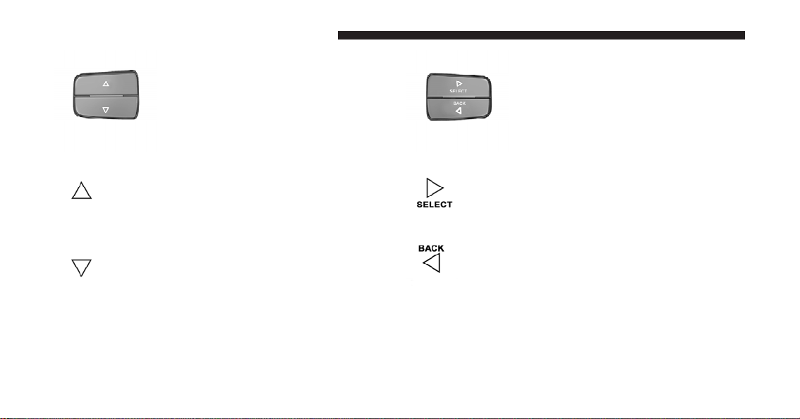
Press and release the UP button to scroll upward through the main menus (DTE, mi/gal,
System Info, Messages, Units, Setup) and sub
menus.
Press and release the DOWN button to scroll
downward through the main menus and sub
menus.
Press and release the SELECT button for access
to main menus, sub menus or to select a
personal setting in the system setup menu.
Press the BACK button to scroll back to a
previous menu or sub menu.
Page 27

EVIC Displays
When the appropriate conditions exist, the EVIC displays
the following messages:
•
Door(s) Ajar (icon only)
•
Key In Ignition
•
Turn Signal On
•
Key Battery Low
•
Coolant Low
•
Oil Change Due
•
Check Fuel Cap
•
Oil Temp High Speed May be Limited
•
Left Front Turn Signal Lamp Out
•
Left Rear Turn Signal Lamp Out
•
Right Front Turn Signal Lamp Out
UNDERSTANDING YOUR INSTRUMENT PANEL 25
•
Right Rear Turn Signal Lamp Out
•
System Setup Unavailable – Vehicle Not in Park
•
System Setup Unavailable – Vehicle in Motion
•
Service Air Filter
•
Perform Service
•
Exhaust Filter XX% Full
•
Exhaust Filter Full – Power Reduced See Dealer
•
Exhaust Service Required – See Dealer Now
•
Exhaust System – Regeneration Required Now
•
Exhaust System – Regeneration In Process
•
Exhaust System – Regeneration Completed
•
Low DEF Refill Soon
•
Refill DEF Engine Will Not Start In XXX Miles
3
Page 28
26 UNDERSTANDING YOUR INSTRUMENT PANEL
•
Refill DEF Engine Will Not Start
•
Service DEF System See Dealer
•
Service DEF Syst Engine Will Not Start in XXX Mi See
Dealer
•
Service DEF System Engine Will Not Start See Dealer
EVIC Warning Lights
Door Ajar Indicator Light
•
This light will turn on to indicate that one or
more door may be ajar.
•
Oil Pressure Warning Light
This light indicates low engine oil pressure. The
light should turn on momentarily when the engine
is started. If the light turns on while driving, stop the
vehicle and shut off the engine as soon as possible. A chime
will sound for four minutes when this light turns on.
Do not operate the vehicle until the cause is corrected.
This light does not show how much oil is in the engine.
The engine oil level must be checked under the hood.
•
Charging System Warning Light
This light shows the status of the electrical charg-
ing system. The light should come on when the
ignition switch is first turned ON and remain on briefly
as a bulb check. If the light stays on or comes on while
driving, turn off some of the vehicle’s non-essential
electrical devices or increase engine speed (if at idle). If
the charging system light remains on, it means that the
vehicle is experiencing a problem with the charging
system. Obtain SERVICE IMMEDIATELY. See an authorized dealer.
If jump starting is required, refer to “Jump Starting” in
“What To Do In Emergencies” for further information.
Page 29

•
Electronic Speed Control Indicator Light
This light will turn on when the electronic
speed control is ON.
•
Electronic Throttle Control (ETC) Warning Light
This light informs you of a problem with the
Electronic Throttle Control (ETC) system. The
light will come on when the ignition is first
turned ON and remain on briefly as a bulb
check. If the light does not come on during starting, have
the system checked by an authorized dealer.
If a problem is detected, the light will come on while the
engine is running. Cycle the ignition key when the
vehicle has completely stopped and the shift lever is
placed in the PARK position. The light should turn off.
UNDERSTANDING YOUR INSTRUMENT PANEL 27
If the light remains lit with the engine running your
vehicle, will usually be drivable, however, see an authorized dealer for service as soon as possible. If the light is
flashing when the engine is running, immediate service is
required and you may experience reduced performance,
an elevated/rough idle or engine stall and your vehicle
may require towing.
•
Engine Temperature Warning Light
This light warns of an overheated engine condition. This indicator will illuminate and a single
chime will sound after reaching a set threshold.
Further overheating will cause the indicator to continuously flash and a continuous chime will occur until the
engine is allowed to cool.
If the light turns on while driving, safely pull over and
stop the vehicle. If the A/C system is on, turn it off. Also,
shift the transmission into NEUTRAL and idle the vehicle. If the temperature reading does not return to
3
Page 30
28 UNDERSTANDING YOUR INSTRUMENT PANEL
normal, turn the engine off immediately and call for
service. Refer to “What To Do In Emergencies/If Your
Engine Overheats” in the Owner’s Manual for more
information.
•
SERV 4WD Warning Light
This light monitors the electric shift 4WD system. If the SERV 4WD warning light stays on or
comes on during driving, it means that the
4WD system is not functioning properly and
that service is required.
•
Transmission Temperature Warning Light
This light indicates that there is excessive transmission fluid temperature that might occur
with severe usage such as trailer towing. It may
also occur when operating the vehicle in a high
torque converter slip condition, such as four-wheel drive
operation (e.g., snow plowing, off-road operation). If this
light comes on, stop the vehicle and run the engine at idle
or faster, with the transmission in NEUTRAL until the
light goes off.
CAUTION!
Continuous driving with the “Transmission Temperature Warning Light” illuminated will eventually
cause severe transmission damage or transmission
failure.
WARNING!
In some circumstances, the “Transmission Temperature Warning Light” under continued operation,
could cause the fluid to boil over, come in contact
with hot engine or exhaust components and cause a
fire.
Page 31

•
Water In Fuel Indicator Light
The “Water In Fuel Indicator Light” will illu-
minate when there is water detected in the fuel
filter. If this light remains on, DO NOT start the
vehicle before you drain the water from the
fuel filter to prevent engine damage. Refer to “Maintenance Procedures/ Draining Fuel/Water Separator Filter” in “Maintaining Your Vehicle” for further information.
•
Wait To Start Light
The “Wait To Start Light” will illuminate when the
ignition is turned to the RUN position and the
intake manifold temperature is below 66°F (19°C). Wait
until the “Wait To Start Light” turns OFF, then start the
vehicle. Refer to “Starting Procedures” in “Starting and
Operating” for further information.
NOTE: The “Wait To Start Light” may not illuminate if
the intake manifold temperature is warm enough.
UNDERSTANDING YOUR INSTRUMENT PANEL 29
Oil Change Due
Your vehicle is equipped with an engine oil change
indicator system. The “Oil Change Due” message will
flash in the EVIC display for approximately 10 seconds
after a single chime has sounded to indicate the next
scheduled oil change interval. The engine oil change
indicator system is duty-cycle based, which means the
engine oil change interval may fluctuate dependent upon
your personal driving style.
Unless reset, this message will continue to display each
time you turn the ignition switch to the ON position. To
turn off the message temporarily, press and release the
RETURN button. To reset the oil change indicator system
(after performing the scheduled maintenance) perform
the following steps.
1. Turn the ignition switch to the ON position. (Do not
start the engine)
3
Page 32

30 UNDERSTANDING YOUR INSTRUMENT PANEL
2. Fully press the accelerator pedal slowly three times
within 10 seconds.
3. Turn the ignition switch to the OFF position.
NOTE: If the indicator message illuminates when you
start the engine, the oil change indicator system did not
reset. If necessary, repeat these steps.
Diesel Exhaust Fluid (DEF) Warning Messages –
Chassis Cab Only
Your vehicle will begin displaying warning messages
when the DEF level reaches a driving range of approximately 1,000 miles (1 609 km). If the following warning
message sequence is ignored, your vehicle will not start
unless DEF is added.
•
Low DEF Refill Soon – This message will display
when the low level is reached, during vehicle start up,
and with increased frequency during vehicle operation. It will be accompanied by a single chime. Approximately 6 gallons (23 Liters) of DEF is required to
refill the tank when this message is initially displayed.
•
Refill DEF Engine Will Not Restart In XXX Miles –
This message will continuously display if the “Low
DEF Refill Soon” message is ignored, and the frequency of occurance of the chime will increase unless
up to 2 gallons (7.5 Liters) of DEF is added to the tank.
The engine will not restart if the mileage counter
reaches zero.
•
Refill DEF Engine Will Not Start – This message will
continuously display when the counter reaches zero,
and will be accompanied by a periodic chime. The
engine will not start after it has been turned off unless
up to 2.5 gallons (9.5 Liters) of DEF is added to the
tank.
Page 33

NOTE: A minimum of up to 2.5 gallons (9.5 Liters) may
be required to restart the engine. Although the vehicle
will continue to operate while this warning message is
initially displayed, the engine will not restart the next
time the vehicle is shut off.
Diesel Exhaust Fluid (DEF) Fault Warning
Messages – Chassis Cab Only
There are three different messages which are displayed if
the vehicle detects that the DEF system has been filled
with a fluid other than DEF, has experienced component
failures, or when tampering has been detected. The
vehicle will not start if the DEF system is not serviced
within less than 250 miles (402 km) of the fault being
detected.
When the DEF system needs to be serviced the following
warnings will display:
•
Service DEF System – See Dealer — This message
will display when the fault is initially detected, each
UNDERSTANDING YOUR INSTRUMENT PANEL 31
time the vehicle is started, and periodically during
driving. The message will be accompanied by a single
chime. We recommend you drive to your nearest
authorized dealer and have your vehicle serviced as
soon as possible.
•
Service DEF System Engine Will Not Start In
200 Miles – See Dealer — This message will display if
the DEF system has not been serviced after the “Service DEF System – See Dealer” message is displayed.
This message will continuously display until the mileage counter reaches zero, and will be accompanied by
a periodic chime. The message will continue to countdown until it reaches zero unless the vehicle is serviced. We recommend you drive to your nearest
authorized dealer and have your vehicle serviced
immediately.
NOTE: Under some circumstances this mileage counter
may start with a value of less than 200 miles (322 km). For
3
Page 34

32 UNDERSTANDING YOUR INSTRUMENT PANEL
example, if recurring faults are detected in a time interval
of less than 40 hours, the counter may restart at the value
where it stopped when a previous fault was temporarily
remedied, or at a minimum of 50 miles (80 km).
•
Service DEF System Engine Will Not Start – See
Dealer — This message will continuously display
when the mileage counter reaches zero, and will be
accompanied by a periodic chime. The engine will not
restart after it has been turned off, your vehicle will
require towing, see your authorized dealer for service.
NOTE: When this message is displayed, the engine will
no longer start after it has been turned off.
Distance To Empty (DTE)
Shows the estimated distance that can be traveled with the
fuel remaining in the tank. This estimated distance is
determined by a weighted average of the instantaneous and
average fuel economy, according to the current fuel tank
level. DTE cannot be reset through the RETURN button.
NOTE: Significant changes in driving style or vehicle
loading will greatly affect the actual drivable distance of
the vehicle, regardless of the DTE displayed value.
When the DTE value is less than 10 miles (16 km)
estimated driving distance, the DTE display will change
to a text display of ⬙LOW FUEL.⬙ This display will
continue until the vehicle runs out of fuel. Adding a
significant amount of fuel to the vehicle will turn off the
⬙LOW FUEL⬙ text and a new DTE value will display.
Trip Functions
Press and release the ODOMETER/TRIP ODOMETER
button until one of the following Trip Functions displays
in the EVIC:
•
Trip A
•
Trip B
•
Elapsed Time
Page 35

Press the ODOMETER/TRIP ODOMETER button to
cycle through all the Trip Computer functions.
The Trip Functions mode displays the following information.
•
Trip A
Shows the total distance traveled for Trip A since the last
reset.
•
Trip B
Shows the total distance traveled for Trip B since the last
reset.
•
Elapsed Time
Shows the total elapsed time of travel since the last reset
when the ignition switch is in the ACC position. Elapsed
time will increment when the ignition switch is in the ON
or START position.
UNDERSTANDING YOUR INSTRUMENT PANEL 33
To Reset The Display
Reset will only occur while a resettable function is being
displayed. Press and release the ODOMETER/TRIP
ODOMETER button once to clear the resettable function
being displayed. To reset all resettable functions, press
and release the ODOMETER/TRIP ODOMETER button a
second time within three seconds of resetting the
currently-displayed function. (Reset ALL will display
during this three-second window).
Vehicle Information (Customer Information Features)
Press and release the UP or DOWN button until “Vehicle
Info” displays in the EVIC and press the SELECT button.
Press the UP and DOWN button to scroll through the
available information displays, then press SELECT to
display anyone of the following choices.
•
DEF Fluid Level – Chassis Cab Only
Displays the Diesel Exhaust Fluid (DEF) fluid level.
3
Page 36

34 UNDERSTANDING YOUR INSTRUMENT PANEL
•
Coolant Temp
Displays the actual coolant temperature.
•
Oil Pressure
Displays the actual oil pressure.
•
Trans Temperature
Displays the actual transmission temperature.
•
Engine Hours
Displays the hours of engine operation.
Compass / Temperature Display
The compass readings indicate the direction
the vehicle is facing. Press and release the
compass button to display one of eight
COMPASS
Button
compass readings and the outside temperature.
NOTE:
•
The system will display the last known outside temperature when starting the vehicle and may need to be
driven several minutes before the updated temperature is displayed. Engine temperature can also affect
the displayed temperature, therefore temperature
readings are not updated when the vehicle is not
moving.
•
During snowplow usage on vehicles equipped with
outside temperature display, the display may show
higher temperatures than the outside ambient temperature. The higher displayed temperature is due to
blocked or reduced airflow to the underhood ambient
temperature sensor caused by the snowplow. In addition, on vehicles equipped with Automatic Temperature Control (ATC), it is suggested that the interior
cabin temperature be manually controlled should the
system not perform as desired while in automatic
mode. Both the outside temperature display and ATC
operation will return to normal when the snowplow is
removed.
Page 37

Automatic Compass Calibration
This compass is self-calibrating, which eliminates the
need to manually reset the compass. When the vehicle is
new, the compass may appear erratic and the EVIC will
display CAL until the compass is calibrated. You may
also calibrate the compass by completing one or more
360–degree turns (in an area free from large metal or
metallic objects) until the CAL indicator displayed in the
EVIC turns off. The compass will now function normally.
UNDERSTANDING YOUR INSTRUMENT PANEL 35
2. Press the UP or DOWN button until the Setup
(Customer-Programmable Features) menu is reached,
then press the SELECT button.
3. Press the DOWN button until “Calibrate Compass” is
displayed in the EVIC.
3
4. Press and release the SELECT button to start the
calibration. The “CAL” indicator will be displayed in the
EVIC.
NOTE: A good calibration requires a level surface and
an environment free from large metallic objects such as
buildings, bridges, underground cables, railroad tracks,
etc.
Manual Compass Calibration
If the compass appears erratic and the CAL indicator
does not appear in the EVIC display, you must put the
compass into the Calibration Mode manually, as follows:
1. Turn ON the ignition switch.
5. Complete one or more 360–degree turns (in an area
free from large metal or metallic objects) until the “CAL”
indicator turns off. The compass will now function
normally.
Compass Variance
Compass Variance is the difference between Magnetic
North and Geographic North. To compensate for the
differences the variance should be set for the zone where
the vehicle is driven, per the zone map. Once properly
Page 38

36 UNDERSTANDING YOUR INSTRUMENT PANEL
set, the compass will automatically compensate for the
differences, and provide the most accurate compass
heading. For the most accurate compass performance, the
compass must be set using the following steps.
NOTE: Keep magnetic materials away from the top of
the instrument panel, such as iPod’s, Cell Phones, Laptops and Radar Detectors. This is where the compass
module is located, and it can cause interference with the
compass sensor, and it may give false readings.
Compass Variance Map
1. Turn the ignition switch ON.
2. Press the UP or DOWN button until the Setup
(Customer-Programmable Features) menu is reached,
then press the SELECT button.
Page 39

3. Press the DOWN button until the “Compass Variance”
message is displayed in the EVIC, then press the SELECT
button. The last variance zone number displays in the
EVIC.
4. Press and release the SELECT button until the proper
variance zone is selected, according to the map.
5. Press and release the RETURN button to exit.
Customer-Programmable Features (System Setup)
Personal Settings allows you to set and recall features
when the transmission is in PARK. If the transmission is
out of PARK or the vehicle begins moving, a warning
message SYSTEM SETUP NOT AVAILABLE, is fol-
lowed in three seconds by, VEHICLE NOT IN PARK.
Press and release the UP or DOWN button until Setup
displays in the EVIC.
UNDERSTANDING YOUR INSTRUMENT PANEL 37
Use the UP or DOWN button to display one of the
following choices.
Select Language
When in this display you may select one of five languages for all display nomenclature, including the trip
functions and the navigation system (if equipped). Press
the UP or DOWN button while in this display and scroll
through the language choices. Press the SELECT button
to select English, Spanish (Español), or French (Français).
Then, as you continue, the information will display in the
selected language.
Nav–Turn By Turn
When this feature is selected, the navigation system
utilizes voice commands, guiding through the drive
route, mile by mile, turn-by-turn until the final destination is reached. To make your selection, press and release
the SELECT button until a check-mark appears next to
3
Page 40

38 UNDERSTANDING YOUR INSTRUMENT PANEL
the feature showing the system has been activated or the
check-mark is removed, showing the system has been
deactivated.
Enable/Disable The Rear Park Assist System
The Rear Park Assist system will scan for objects behind
the vehicle when the transmission is in the REVERSE and
the vehicle speed is less than 11 mph (18 km/h). The
system can be enabled with Sound Only, Sound and
Display, or turned OFF through the EVIC. To make your
selection, press and release the SELECT button until a
check-mark appears next to the feature showing the
system has been activated or the check-mark is removed,
showing the system has been deactivated. Refer to “Rear
Park Assist System” in “Understanding The Features Of
Your Vehicle” for system function and operating
information.
Auto Lock Doors
When this feature is selected, all doors will lock automatically when the vehicle reaches a speed of 15 mph
(24 km/h). To make your selection, press and release the
SELECT button until a check-mark appears next to the
feature showing the system has been activated, or the
check-mark is removed showing the system has been
deactivated.
Auto Unlock Doors
When this feature is selected, all doors will unlock when
the vehicle is stopped and the transmission is in the
PARK or NEUTRAL position and the driver’s door is
opened. To make your selection, press and release the
SELECT button until a check-mark appears next to the
feature showing the system has been activated, or the
check-mark is removed showing the system has been
deactivated.
Page 41

1st Press RKE
When Driver Door 1st Press is selected, only the driver’s
door will unlock on the first press of the RKE transmitter
UNLOCK button. When Driver Door 1st Press is selected,
you must press the RKE transmitter UNLOCK button
twice to unlock the passenger’s doors. When All Doors
1st Press is selected, all of the doors will unlock on the
first press of the RKE transmitter UNLOCK button. To
make your selection, press and release the SELECT
button until “Driver Door 1st Press” or “All Doors 1st
Press” appears.
RKE Linked To Memory
When this feature is selected the memory seat, mirror,
and radio settings will return to the memory set position
when the RKE transmitter UNLOCK button is pressed. If
this feature is not selected then the memory seat, mirror,
and radio settings can only return to the memory set
position using the seat mounted switch. To make your
selection, press and release the SELECT button until a
UNDERSTANDING YOUR INSTRUMENT PANEL 39
check-mark appears next to the feature showing the
system has been activated or the check-mark is removed,
showing the system has been deactivated.
Horn With Remote Start
When this feature is selected, a short horn sound will
occur when the RKE transmitter REMOTE START button
is pressed. To make your selection, press and release the
SELECT button until a check-mark appears next to the
feature showing the system has been activated or the
check-mark is removed, showing the system has been
deactivated.
Horn With Remote Lock
When this feature is selected, a short horn sound will
occur when the RKE transmitter LOCK button is pressed.
This feature may be selected with or without the Flash
Lamps with Lock feature. To make your selection, press
3
Page 42

40 UNDERSTANDING YOUR INSTRUMENT PANEL
and release the SELECT button until a check-mark appears next to the feature showing the system has been
activated or the check-mark is removed, showing the
system has been deactivated.
Flash Lamps With Lock
When this feature is selected, the front and rear turn
signals will flash when the doors are locked or unlocked
with the RKE transmitter. This feature may be selected
with or without the sound horn on lock feature selected.
To make your selection, press and release the SELECT
button until a check-mark appears next to the feature
showing the system has been activated or the check-mark
is removed, showing the system has been deactivated.
Headlamp Off Delay
When this feature is selected, the driver can choose to have
the headlights remain on for 0, 30, 60, or 90 seconds when
exiting the vehicle. To make your selection, press and
release the SELECT button until 0, 30, 60, or 90 appears.
Headlamps With Wipers
When this feature is selected and the HEADLIGHT
switch is in the AUTO position, the headlights will turn
on approximately 10 seconds after the wipers are turned
on. The headlights will also turn off when the wipers are
turned off if they were turned on by this feature. To make
your selection, press and release the SELECT button until
a check-mark appears next to the feature showing the
system has been activated or the check-mark is removed,
showing the system has been deactivated.
Wiper Mode – If Equipped
When this feature is selected, the system will automatically
activate the windshield wipers if it senses moisture on the
windshield. To make your selection, press and release the
SELECT button until a check-mark appears next to the
feature showing the system has been activated or the
check-mark is removed, showing the system has been
deactivated. When this feature is deactivated, the system
reverts to the standard intermittent wiper operation.
Page 43

Easy Exit Seat – If Equipped
When this feature is selected it provides automatic driver
seat positioning to enhance driver mobility when entering and exiting the vehicle. To make your selection, press
and release the SELECT button until a check-mark appears next to the feature showing the system has been
activated or the check-mark is removed, showing the
system has been deactivated.
NOTE: The seat will return to the memorized seat
location (if Recall Memory with Remote Key Unlock is set
to ON) when the RKE transmitter is used to unlock the
door. Refer to “Driver Memory Seat” in “Understanding
The Features Of Your Vehicle” for further information.
Tilt Mirror In Reverse
When this feature is selected and the shift lever is placed
in reverse gear, the side mirrors tilt downward to allow
the driver to see into the previous blind spot and avoid
objects in close proximity to the rear of the vehicle. To
make your selection, press and release the SELECT
UNDERSTANDING YOUR INSTRUMENT PANEL 41
button until a check-mark appears next to the feature
showing the system has been activated or the check-mark
is removed, showing the system has been deactivated.
Key-Off Power Delay
When this feature is selected, the power window
switches, radio, hands-free system (if equipped), DVD
video system (if equipped), power sunroof (if equipped),
and power outlets will remain active for up to 10 minutes
after the ignition switch is turned OFF. Opening a vehicle
door will cancel this feature. To make your selection,
press and release the SELECT button until Off, 45 sec.,
5 min., or 10 min. appears.
Illuminated Approach
When this feature is selected, the headlights will activate
and remain on for up to 90 seconds when the doors are
unlocked with the RKE transmitter. To make your selection, press and release the SELECT button until “OFF,”
“30 sec.,” “60 sec.,” or “90 sec.” appears.
3
Page 44

42 UNDERSTANDING YOUR INSTRUMENT PANEL
Hill Start Assist (HSA) – If Equipped
When on is selected, the HSA system is active. Refer to
“Electronic Brake Control System” in “Starting And
Operating” for system function and operating information. To make your selection, press and release the
SELECT button until a check-mark appears next to the
feature showing the system has been activated or the
check-mark is removed, showing the system has been
deactivated.
Display Units Of Measure In
The EVIC, odometer, and navigation system (if
equipped) can be changed between English and Metric
units of measure. To make your selection, press and
release the SELECT button until ENGLISH or METRIC
appears.
Compass Variance
Refer to “Compass Display” for more information.
Calibrate Compass
Refer to “Compass Display” for more information.
Page 45

CONTENTS
STARTING AND OPERATING
䡵 Starting Procedures ..................... 46
▫ Manual Transmission – If Equipped ........ 46
▫ Automatic Transmission – If Equipped ...... 46
▫ Extreme Cold Weather .................. 46
▫ Normal Starting Procedure –
Engine Manifold Air Temperature Above
66°F (19°C) .......................... 47
▫ Starting Procedure – Engine Manifold Air
Temperature 0°F To 66°F (–18°C To 19°C) .... 48
▫ Starting Procedure – Engine Manifold Air
Temperature Below 0°F (-18°C) ............ 49
▫ Starting Fluids ....................... 51
䡵 Normal Operation – Diesel Engine .......... 51
▫ Cold Weather Precautions ............... 52
▫ Engine Idling ........................ 54
▫ Stopping The Engine ................... 55
▫ Engine Speed Control .................. 57
▫ Operating Precautions .................. 57
4
Page 46

44 STARTING AND OPERATING
▫ Cooling System Tips – Automatic
Transmission ........................ 57
䡵 Engine Block Heater — If Equipped ......... 59
▫ Block Heater Usage .................... 59
▫ Downshifting ........................ 77
▫ Reverse Shifting ...................... 79
䡵 Power Take Off Operation — If Equipped
(Chassis Cab Only) ...................... 79
䡵 Diesel Exhaust Brake (Engine Braking) — If
Equipped ............................. 60
䡵 Automatic Transmission — If Equipped ....... 62
▫ Brake/Transmission Shift Interlock System . . . 63
▫ Six-Speed Automatic Transmission With
Overdrive (68RFE) – If Equipped (Ram Truck
Only) .............................. 63
▫ Automatic Transmission With Overdrive
(AS68RC) – If Equipped (Chassis Cab Only) . . 69
䡵 Manual Transmission — If Equipped ......... 76
▫ Shifting ............................ 76
▫ Stationary Mode ...................... 80
▫ Mobile Mode ........................ 81
▫ Power Take Off – Aftermarket Installation .... 82
䡵 Engine Runaway ....................... 82
䡵 Fuel Requirements ...................... 83
▫ Fuel Specifications .................... 84
䡵 Adding Fuel .......................... 84
▫ Fuel Filler Cap ....................... 85
▫ Avoid Using Contaminated Fuel ........... 85
Page 47

▫ Bulk Fuel Storage – Diesel Fuel ........... 85
STARTING AND OPERATING 45
䡵 Diesel Exhaust Fluid — Chassis Cab Only ..... 89
▫ Diesel Exhaust Fluid Storage ............. 86
▫ Adding Diesel Exhaust Fluid – Chassis Cab
Only .............................. 87
▫ System Overview ..................... 89
4
Page 48

46 STARTING AND OPERATING
STARTING PROCEDURES
Before starting your vehicle, adjust your seat, adjust both
inside and outside mirrors, and fasten your seat belts.
The starter should not be operated for more than 15second intervals. Waiting a few minutes between such
intervals will protect the starter from overheating.
WARNING!
Do not leave children or animals inside parked
vehicles in hot weather. Interior heat build up may
cause serious injury or death.
Manual Transmission – If Equipped
Apply the parking brake, place the shift lever in NEUTRAL and press the clutch pedal to the floor before
starting the vehicle. This vehicle is equipped with a
clutch interlocking ignition system. It will not start unless
the clutch is fully pressed.
Automatic Transmission – If Equipped
Start the engine with the shift lever in NEUTRAL or
PARK position. Apply the brake before shifting to any
driving range.
Tip Start Feature
Do not press the accelerator. Turn the ignition switch
briefly to the START position and release it. The starter
motor will continue to run but will automatically disengage when the engine is running.
Extreme Cold Weather
The Cummins威 diesel engine is equipped with several
features designed to assist cold weather starting and
operation:
•
The engine block heater is a resistance heater installed
in the water jacket of the engine just above and behind
the oil filter. It requires a 110–115 Volt AC electrical
outlet with a grounded, three-wire extension cord.
Page 49

NOTE: The engine block heater cord is a factory installed option. If your vehicle is not equipped, heater
cords are available from your authorized MOPAR威
dealer.
•
A 12 Volt heater built into the fuel filter housing aids in
preventing fuel gelling. It is controlled by a built-in
thermostat.
•
A heated intake air system both improves engine
starting and reduces the amount of white smoke
generated by a warming engine.
Normal Starting Procedure – Engine Manifold Air Temperature Above 66°F (19°C)
Observe the instrument panel cluster lights when starting
the engine.
1. Always apply the parking brake.
STARTING AND OPERATING 47
2. Shift into PARK for an automatic transmission. For
vehicles equipped with a manual transmission, fully
press and hold the clutch pedal and shift into NEUTRAL.
3. Turn the ignition switch to the ON position and watch
the instrument panel cluster lights.
CAUTION!
4
If the “Water in Fuel Indicator Light” remains on, DO
NOT START the engine before you drain the water
from the fuel filter to avoid engine damage. Refer to
“Maintenance Procedures/Draining Fuel/Water Separator Filter” in “Maintaining Your Vehicle” for further information.
4. Turn the ignition switch to the START position and
crank the engine. Do not press the accelerator during
starting.
Page 50

48 STARTING AND OPERATING
CAUTION!
Do not crank engine for more than 15 seconds at a
time or starter motor damage may result. Turn the
ignition switch to the OFF position and wait at least
two minutes for the starter to cool before repeating
start procedure.
“Electronic Vehicle Information Center (EVIC)” in “Understanding Your Instrument Panel” for further information. When engine temperatures fall below 66°F (19°C)
the “Wait To Start Light” will remain on indicating the
intake manifold heater system is active.
Follow the steps in the “Normal Starting” procedure
except:
5. When the engine starts, release the key fob.
6. Check to see that there is oil pressure.
7. Release the parking brake.
Starting Procedure – Engine Manifold Air Temperature 0°F To 66°F (–18°C to 19°C)
NOTE: The temperature displayed in the Electronic
Vehicle Information Center (EVIC) does not necessarily
reflect the engine manifold air temperature. Refer to
1. The “Wait To Start Light” will remain on for a period
of time (length of time depends on engine temperature).
CAUTION!
If the “Water in Fuel Indicator Light” remains on, DO
NOT START engine before you drain the water from
the fuel filter to avoid engine damage. Refer to
“Maintenance Procedures/Draining Fuel/Water Separator Filter” in “Maintaining Your Vehicle” for further information.
Page 51

2. After the “Wait To Start Light” goes off, turn the
ignition switch to the START position. Do not press the
accelerator during starting.
CAUTION!
Do not crank engine for more than 15 seconds at a
time or starter motor damage may result. Turn the
ignition switch to the OFF position and wait at least
two minutes for the starter to cool before repeating
start procedure.
3. After engine start-up, check to see that there is oil
pressure.
4. Allow the engine to idle about three minutes until the
manifold heaters have completed the post-heat cycle.
5. Release the parking brake and drive.
STARTING AND OPERATING 49
NOTE:
•
Engine idle speed will automatically increase to 1,000
RPM at low coolant temperatures to improve engine
warm-up.
•
If the engine stalls, or if the ignition switch is left ON
for more than two minutes after the “Wait To Start
Light” goes out, reset the grid heaters by turning the
ignition switch to the OFF position for at least five
seconds and then back ON. Repeat steps 1 through 5 of
“Starting Procedure – Engine Manifold Air Temperature Below 66°F (19°C).”
Starting Procedure – Engine Manifold Air Temperature Below 0°F (-18°C)
In extremely cold weather below 0°F (-18°C) it may be
beneficial to cycle the manifold heaters twice before
attempting to start the engine. This can be accomplished
by turning the ignition OFF for at least five seconds and
then back ON after the “Wait To Start Light” has turned
4
Page 52

50 STARTING AND OPERATING
off, but before the engine is started. However, excessive
cycling of the manifold heaters will result in damage to
the heater elements or reduced battery voltage.
NOTE: If multiple pre-heat cycles are used before
starting, additional engine run time may be required to
maintain battery state of charge at a satisfactory level.
3. If the vehicle is driven and vehicle speed exceeds
19 mph (31 km/h) before the manifold heater post-heat
(after start) cycle is complete, the manifold heaters will
shut off.
4. If the engine is started before the “Wait To Start Light”
turns off, the preheat cycle will turn off.
1. If the engine stalls after the initial start, the ignition
must be turned to the OFF position for at least five
seconds and then to the ON position to recycle the
manifold heaters.
NOTE: Excessive white smoke and poor engine performance will result if manifold heaters are not recycled.
2. Heat generated by the manifold heaters dissipates
rapidly in a cold engine. If more than two minutes pass
between the time the “Wait To Start Light” turns off and
the engine is started, recycle the manifold heaters by
turning the ignition switch to the OFF position for at least
five seconds and then back ON.
5. If the engine is cranked for more than 10 seconds, the
post-heat cycle will turn off.
NOTE:
•
Engine idle speed will automatically increase to 1, 000
RPM at low coolant temperatures to improve engine
warm-up.
•
When a diesel engine is allowed to run out of fuel or
the fuel gels at low temperatures, air is pulled into the
fuel system. If your engine has run out of fuel, refer to
“Maintenance Procedures/Priming If The Engine Has
Run Out Of Fuel” in “Maintaining Your Vehicle” for
further information.
Page 53

Starting Fluids
STARTING AND OPERATING 51
WARNING!
WARNING!
Starting fluids or flammable liquids are never to be
used in the Cummins威 diesel engine (see Warning
label). Never pour diesel fuel, flammable liquid,
starting fluids (ether) into the air cleaner canister, air
intake piping, or turbocharger inlet in an attempt to
start the vehicle. This could result in a flash fire and
explosion causing serious personal injury and engine
damage.
The engine is equipped with an automatic electric air
preheating system. If the instructions in this manual are
followed, the engine should start in all conditions.
Do not leave children or animals inside parked
vehicles in hot weather. Interior heat build up may
cause serious injury or death.
NORMAL OPERATION – DIESEL ENGINE
Observe the following when the engine is operating.
•
All message center lights are off.
•
Malfunction Indicator Light (MIL) is off.
•
Engine oil pressure is above 10 psi (69 kPa) at idle.
•
Voltmeter operation:
•
The voltmeter may show a gauge fluctuation at
various engine temperatures. This cycling operation
is caused by the post-heat cycle of the intake manifold heater system. The number of cycles and the
length of the cycling operation is controlled by the
4
Page 54

52 STARTING AND OPERATING
engine control module. Post-heat operation can run
for several minutes, and then the electrical system
and voltmeter needle will stabilize.
•
The cycling action will cause temporary dimming of
the headlamps, interior lamps, and also a noticeable
reduction in blower motor speed.
Cold Weather Precautions
Operation in ambient temperature below 32°F (0°C) may
require special considerations. The following charts suggest these options:
Fuel Operating Range
NOTE: Use “Ultra Low Sulfur Diesel Fuels” ONLY.
*No. 1 Ultra Low Sulfur Diesel Fuel should only be used
where extended arctic conditions (-10°F/-23°C) exist.
NOTE:
•
Use of Climatized Ultra Low Sulfur Diesel Fuel or
Number 1 Ultra Low Sulfur Diesel Fuel results in a
noticeable decrease in fuel economy.
•
Climatized Ultra Low Sulfur Diesel Fuel is a blend of
Number 2 Ultra Low Sulfur and Number 1 Ultra Low
Sulfur Diesel Fuels which reduces the temperature at
which wax crystals form in fuel.
Page 55

•
The engine requires the use of “Ultra Low Sulfur
Diesel Fuel”. Use of incorrect fuel could result in
engine and exhaust system damage. Refer to “Fuel
Requirements” in “Starting and Operating” for further
information.
Engine Oil Usage
Refer to “Maintenance Procedures” in “Maintaining Your
Vehicle” for the correct engine oil viscosity.
Winter Front Usage
If a winter front or cold weather cover is to be used, a
percentage of the total grille opening area must be left
uncovered to provide sufficient air flow to the charge air
cooler and automatic transmission oil cooler. The percentage of opening must be increased with the increasing
ambient air temperature and/or engine load. If the
cooling fan can be heard cycling frequently, increase the
size of the opening in the winter front. A suitable cold
weather cover is available from your MOPAR威 dealer.
STARTING AND OPERATING 53
Battery Blanket Usage
A battery loses 60% of its cranking power as the battery
temperature decreases to 0°F (-18°C). For the same decrease in temperature, the engine requires twice as much
power to crank at the same RPM. The use of 120 VAC
powered battery blankets will greatly increase starting
capability at low temperatures. Suitable battery blankets
are available from your authorized MOPAR威 dealer.
Engine Warm-Up
Avoid full throttle operation when the engine is cold.
When starting a cold engine, bring the engine up to
operating speed slowly to allow the oil pressure to
stabilize as the engine warms up.
NOTE: High-speed, no-load running of a cold engine
can result in excessive white smoke and poor engine
performance. No-load engine speeds should be kept
under 1,200 RPM during the warm-up period, especially
in cold ambient temperature conditions.
4
Page 56

54 STARTING AND OPERATING
Your vehicle is equipped with a turbo speed limiter, this
feature limits the engine speed to 1,200 RPM when
engine coolant temperatures are below 70°F (21°C). This
feature is designed to protect the turbocharger from
damage and will only operate in PARK or NEUTRAL.
If temperatures are below 32°F (0°C), operate the engine
at moderate speeds for five minutes before full loads are
applied.
NOTE:
•
If ambient temperatures are low and the coolant
temperature is below 180°F (82°C), the engine idle
speed will slowly increase to 1,000 RPM after two
minutes of idle, if the following conditions are met:
•
foot is off brake pedal and throttle pedal
•
automatic transmission is in PARK
•
vehicle speed is zero
•
Applying the throttle will cancel fast idle
•
If the engine is equipped with an exhaust brake,
operating the exhaust brake at idle will greatly improve warm up rate and will help keep the engine
close to operating temperature during extended idle.
Engine Idling
Avoid prolonged idling, long periods of idling may be
harmful to your engine because combustion chamber
temperatures can drop so low that the fuel may not burn
completely. Incomplete combustion allows carbon and
varnish to form on piston rings, engine valves, and
injector nozzles. Also, the unburned fuel can enter the
crankcase, diluting the oil and causing rapid wear to the
engine.
If the engine is allowed to idle, under some conditions
the idle speed may increase to 900 RPM then return to
normal idle speed. This is normal operation.
NOTE: For EVIC messages related to the vehicle’s
exhaust system, refer to “Maintenance Procedures/
Page 57

Intervention Regeneration Strategy – EVIC Message Process Flow” in “Maintaining Your Vehicle” for further
information.
Idle-Up Feature – Automatic Transmission Only
The driver-controlled high idle speed feature will help
increase cylinder temperatures and provide additional
cab heat, however, excessive idling may still cause the
exhaust aftertreatment system to not properly regenerate.
Extended periods of idle time should be avoided.
STARTING AND OPERATING 55
2. The engine RPM will go up to 1100 RPM. To increase
the RPM, press and hold the ACCEL/RESUME switch
and the idle speed will increase to approximately 1500
RPM. To decrease the RPM, press and hold the DECEL
switch and the idle speed will decrease to approximately
1100 RPM.
3. To cancel the Idle–Up feature, either press the CANCEL switch, press the ON/OFF switch, or press the brake
pedal.
4
The Idle-Up feature uses the speed control switches to
increase engine idle speed and quickly warm the vehicle’s interior.
1. With the transmission in PARK, the parking brake
applied, and the engine running, press the speed control
switch to the ON position, then press the SET switch.
Stopping The Engine
Idle the engine a few minutes before routine shutdown.
After full load operation, idle the engine three to five
minutes before shutting it down. This idle period will
allow the lubricating oil and coolant to carry excess heat
away from the combustion chamber, bearings, internal
components, and turbocharger. This is especially important for turbocharged, charge air-cooled engines.
Page 58

56 STARTING AND OPERATING
NOTE:
•
During engine shut down on vehicles equipped with
manual transmissions, it is normal for the diesel
engine to resonate heavily for a moment during engine
shut off. When the engine is connected to a manual
transmission, this resonance causes load gear rattle
from the transmission. This is commonly referred to as
“shut down rattle.” The manufacturer recommends
performing engine shut down with the clutch pedal
pushed to the floor (clutch disengaged). When engine
shut down is performed in this manner the rattle is
reduced (not eliminated).
•
Refer to the following chart for proper engine
shutdown.
Driving
Condition
Stop and
Load
Empty Cool Less than
Go
Stop and
Medium One
Go
Highway
Medium Warm Two
Speeds
City Traffic Maximum
GCWR
Highway
Speeds
Uphill
Grade
Maximum
GCWR
Maximum
GCWR
Turbo-
charger
Temperature
Hot Five
Idle Time
(min.) Be-
fore Engine
Shutdown
One
Three
Four
Page 59

Engine Speed Control
CAUTION!
Prevent overspeeding the engine going downhill.
When descending steep grades, use a combination of
gears and service brakes to control vehicle/engine
speed. Overspeed can cause severe engine damage.
Operating Precautions
Avoid Overheating The Engine
The temperature of the engine coolant (antifreeze) (a
mixture of 50% ethylene-glycol and 50% water) must not
exceed the normal range of the temperature gauge 240°F
(116°C) with a 16 psi (110 kPa) radiator cap.
Usually the engine coolant (antifreeze) temperature indicated during operation will be to the left of center in the
normal range of the gauge.
STARTING AND OPERATING 57
Avoid Low Coolant Temperature Operation
Continual operation at low engine coolant (antifreeze)
temperature below the normal range on the gauge 140°F
(60°C) can be harmful to the engine. Low engine coolant
(antifreeze) temperature can cause incomplete combustion which allows carbon and varnish to form on piston
rings and injector nozzles. Also, the unburned fuel can
enter the crankcase, diluting the lubricating oil and
causing rapid wear to the engine.
Cooling System Tips – Automatic Transmission
To reduce potential for engine and transmission overheating in high ambient temperature conditions, take the
following actions:
•
City Driving —
When stopped, shift the transmission into NEUTRAL
and increase engine idle speed.
•
Highway Driving —
Reduce your speed.
4
Page 60

58 STARTING AND OPERATING
•
Up Steep Hills —
Select a lower transmission gear, but try and keep the
torque converter clutch engaged.
•
Air Conditioning —
Turn it off temporarily.
Do Not Operate The Engine With Low Oil
Pressure
When the engine is at normal operating temperature, the
minimum oil pressures required are:
Idle 700 to 800 RPM ...............10psi(69kPa)
Full speed and load .............. 30psi(207 kPa)
CAUTION!
If oil pressure falls to less than normal readings, shut
the engine off immediately. Failure to do so could
result in immediate and severe engine damage.
Do Not Operate The Engine With Failed Parts
Practically all failures give some warning before the parts
fail. Be on the alert for changes in performance, sounds,
and visual evidence that the engine requires service.
Some important clues are:
•
engine misfiring or vibrating severely
•
sudden loss of power
•
unusual engine noises
•
fuel, oil or coolant leaks
•
sudden change, outside the normal operating range, in
the engine operating temperature
•
excessive smoke
•
oil pressure drop
Page 61

ENGINE BLOCK HEATER — IF EQUIPPED
The engine block heater warms engine coolant and
permits quicker starts in cold weather. Connect the heater
cord to a ground-fault interrupter protected 110–115 Volt
AC electrical outlet with a grounded, three-wire extension cord.
The engine block heater cord is routed under the hood to
the right side and can be located just behind the grille
near the headlamp.
NOTE: The engine block heater cord is a factory installed option. If your vehicle is not equipped, heater
cords are available from your authorized MOPAR威
dealer.
The block heater must be plugged in at least one hour to
have an adequate warming effect on the coolant.
STARTING AND OPERATING 59
WARNING!
Remember to disconnect the cord before driving.
Damage to the 110–115 Volt electrical cord could
cause electrocution.
NOTE: The block heater will require 110 Volts AC and
6.5 Amps to activate the heater element.
Block Heater Usage
For ambient temperatures below 0°F (-18°C), engine
block heater usage is recommended.
For ambient temperatures below –20°F (-29°C), engine
block heater usage is required.
4
Page 62

60 STARTING AND OPERATING
DIESEL EXHAUST BRAKE (ENGINE BRAKING) — IF EQUIPPED
The exhaust brake feature will only function when the
driver turns the exhaust brake switch to the ON position.
Exhaust Brake Switch
Once the switch is in the ON position and the vehicle is
moving faster than 5 mph (8 km/h); the exhaust brake
will automatically operate when the driver removes
pressure from the accelerator pedal. Exhaust braking is
most effective when the engine RPM is higher. The
automatic transmission has been programmed in TOW/
HAUL mode only to downshift more aggressively when
the exhaust brake is enabled to increase brake performance.
CAUTION!
Use of aftermarket exhaust brakes is not recommended and could lead to engine damage
Page 63

WARNING!
Do not use the exhaust brake feature when driving in
icy or slippery conditions as the increased engine
braking can cause the rear wheels to slide and the
vehicle to swing around with the possible loss of
vehicle control, which may cause an accident possibly resulting in personal injury or death.
NOTE: For optimum braking power it is recommended
to use the exhaust brake while in TOW/HAUL mode.
The purpose of the exhaust brake (engine braking) feature is to supply negative (braking) torque to the engine.
Typically, the engine braking is used for, but not limited
to, vehicle towing applications where vehicle braking can
be achieved by the internal engine power, thereby sparing the mechanical brakes of the vehicle.
STARTING AND OPERATING 61
Benefits of the exhaust brake are:
•
vehicle driving control
•
reduced brake fade
•
longer brake life
•
faster cab warm-up.
The exhaust brake feature can also be used to reduce the
engine warm up time. To use the exhaust brake as a
warm-up device, the vehicle must be stopped or moving
less than 5 mph (8 km/h), the exhaust brake switch must
be in the ON position, and the coolant temperature must
be below 180°F (82°C) and ambient temperature below
60°F (16°C).
4
Page 64

62 STARTING AND OPERATING
AUTOMATIC TRANSMISSION — IF EQUIPPED
WARNING!
CAUTION!
Damage to the transmission may occur if the following precautions are not observed:
•
Shift into PARK only after the vehicle has come to
a complete stop.
•
Shift into or out of REVERSE only after the
vehicle has come to a complete stop and the engine
is at idle speed.
•
Do not shift from REVERSE, PARK, or NEUTRAL
into any forward gear when the engine is above
idle speed.
•
Before shifting into any gear, make sure your foot
is firmly on the brake pedal.
•
Unintended movement of a vehicle could injure
those in and near the vehicle. As with all vehicles,
you should never exit a vehicle while the engine is
running. Before exiting a vehicle, you should
always shift the transmission into PARK, remove
the key fob from the ignition, and apply the
parking brake. Once the key fob is removed from
the ignition, the shift lever is locked in the PARK
position, securing the vehicle against unwanted
movement. Furthermore, you should never leave
unattended children inside a vehicle.
(Continued)
Page 65

WARNING! (Continued)
•
It is dangerous to move the shift lever out of PARK
or NEUTRAL if the engine speed is higher than
idle speed. If your foot is not firmly on the brake
pedal, the vehicle could accelerate quickly forward
or in reverse. You could lose control of the vehicle
and hit someone or something. Only shift into
gear when the engine is idling normally and when
your right foot is firmly on the brake pedal.
Brake/Transmission Shift Interlock System
This vehicle is equipped with a Brake Transmission Shift
Interlock System (BTSI) that holds the shift lever in the
PARK position when the ignition switch is in the LOCK
position. To move the shift lever out of the PARK
position, the ignition switch must be turned to any other
switch position (ACC, ON, or START) (engine running or
not) and the brake pedal must be pressed.
STARTING AND OPERATING 63
Six-Speed Automatic Transmission With Overdrive (68RFE) – If Equipped (Ram Truck Only)
The shift lever display located in the instrument panel
cluster indicates the transmission gear range (the selector
is illuminated for night driving). The shift lever is
mounted on the right side of the steering column. You
must press the brake pedal to pull the shift lever out of
PARK position (Brake Interlock System). To drive, move
the shift lever from PARK or NEUTRAL to the desired
DRIVE position. Pull the shift lever toward you when
shifting into REVERSE or PARK, or when shifting out of
PARK.
Electronic Range Select (ERS) Operation
The Electronic Range Select (ERS) shift control allows
you to move the switch down (-) or up (+) when the
shifter is in the D (Drive) position, allowing the selection
of the desired top gear. For example, if the driver shifts
4
Page 66

64 STARTING AND OPERATING
the transmission into third gear, the transmission will
never shift above third gear, but can shift down into
second or first gear, when needed.
Column Shift Lever
Switching from ERS to D-Mode can be done at any
vehicle speed. To switch from “Drive” mode to “ERS”
mode, press the switch down (-) once. The current gear
will be maintained as the top gear. To disable ERS, simply
press and hold the switch up (+) until “D” is displayed in
the instrument cluster odometer.
WARNING!
Do not downshift for additional engine braking on a
slippery surface. The drive wheels could lose their
grip and the vehicle could skid.
Screen Display 12345D
Actual Gear(s)
Allowed
NOTE: To select the proper gear position for maximum
deceleration (engine braking), simply press and hold the
switch down (-). The transmission will shift to the range
from which the vehicle can best be slowed down.
1 1-2 1-3 1-4 1-5 1-6
Page 67

Gear Ranges
DO NOT race the engine when shifting from PARK or
NEUTRAL position into another gear range.
PARK
This range supplements the parking brake by locking the
transmission. The engine can be started in this range.
Never use PARK while the vehicle is in motion. Apply
the parking brake when leaving the vehicle in this range.
Always apply the parking brake first, then place the shift
lever into the PARK position. On four-wheel drive vehicles be sure that the transfer case is in a drive position.
STARTING AND OPERATING 65
WARNING!
•
Never use the PARK position as a substitute for
the parking brake. Always apply the parking
brake fully when parked to guard against vehicle
movement and possible injury or damage.
•
Your vehicle could move and injure you and others
if it is not completely in PARK. Check by trying to
move the shift lever back and forth without first
pulling it toward you after you have set it in
PARK. Make sure it is in PARK before leaving the
vehicle.
(Continued)
4
Page 68

66 STARTING AND OPERATING
WARNING! (Continued)
•
It is dangerous to move the shift lever out of PARK
or NEUTRAL if the engine speed is higher than
idle speed. If your foot is not firmly on the brake
pedal, the vehicle could accelerate quickly forward
or in reverse. You could lose control of the vehicle
and hit someone or something. Only shift into
gear when the engine is idling normally and when
your foot is firmly on the brake pedal.
REVERSE
This range should be used only after the vehicle has come
to a complete stop.
NEUTRAL
Use this range when the vehicle is standing for prolonged
periods with the engine running. The engine may be
started in this range. Set the parking brake if you must
leave the vehicle.
DRIVE
This range provides underdrive first, second and third
gears, direct fourth gear and overdrive fifth and sixth
gears. The shift into overdrive fifth and sixth gear occurs
only after the transmission has completed the shift into
fourth gear. No other movement of the shift mechanism
is required to complete the 4–5 or 5–6 gear shifts.
Upshifts into both overdrive gears, fifth and sixth, will be
delayed when the transmission fluid temperature is
below 40°F (4.5°C) or above 240°F (115.5°C).
NOTE: Use caution when operating a heavily loaded
vehicle in second or first gear in high ambient temperatures as torque converter slip can impose significant
additional heat load on the cooling system.
Overdrive Operation
The overdrive automatic transmission contains an electronically controlled fifth and sixth (Overdrive). The
Page 69

transmission will automatically shift from DRIVE to
Overdrive if the following conditions are present:
•
the shift lever is in DRIVE;
•
the engine coolant has reached normal operating temperature;
•
vehicle speed is above approximately 30 mph
(48 km/h);
•
the “TOW/HAUL” switch has not been activated;
•
transmission has reached normal operating
temperature.
NOTE: If the vehicle is started in extremely cold temperatures, the transmission may not shift into Overdrive
and will automatically select the most desirable gear for
operation at this temperature. Normal operation will
resume when the transmission fluid temperature has
risen to a suitable level. Refer to the “Note” under
“Torque Converter Clutch” later in this section.
STARTING AND OPERATING 67
If the transmission temperature gets extremely hot, the
transmission will automatically select the most desirable
gear for operation at this temperature. If the transmission
temperature becomes hot enough the “Transmission
Temperature Warning Light” may illuminate and the
transmission may downshift out of Overdrive until the
transmission cools down. After cool down, the transmission will resume normal operation.
The transmission will downshift from Overdrive to
DRIVE if the accelerator pedal is fully pressed at vehicle
speeds above approximately 35 mph (56 km/h).
When To Use TOW/HAUL
When driving in hilly areas, towing a trailer, carrying a
heavy load, etc., and frequent transmission shifting occurs, press the “TOW/HAUL” switch once to select
“TOW/HAUL.” In “TOW/HAUL” mode, fourth to fifth
gear upshifts are delayed. Shifts into fifth and sixth gear
are still allowed under steady cruise conditions. Closed
4
Page 70

68 STARTING AND OPERATING
throttle downshifts (for improved engine braking) may
occur during steady braking maneuvers. Pressing the
switch a second time restores normal operation. Normal
operation is always the default at engine start-up.
TOW/HAUL Switch
The “TOW/HAUL Indicator Light” will illuminate in the
instrument cluster to indicate when the switch has been
activated. If the “TOW/HAUL” modes are desired, the
button must be pressed each time the engine is started.
Torque Converter Clutch
A feature designed to improve fuel economy has been
included in the automatic transmission on your vehicle.
A clutch within the torque converter engages automatically at calibrated speeds. This may result in a slightly
different feeling or response during normal operation in
the upper gears. When the vehicle speed drops or during
acceleration when the transmission downshifts to second
gear, the clutch automatically disengages.
NOTE:
•
The torque converter clutch will not engage, and the
transmission will not shift to sixth gear, until the
transmission fluid and engine coolant are warm [usually after 1-3 miles (1.6 - 4.8 km) of driving]. Because
Page 71

sixth gear is disabled, and engine speed is higher
when the torque converter clutch is not engaged, it
may seem as if the transmission is not shifting properly when cold. This is normal. Using the Electronic
Range Select (ERS) feature, when the transmission is
sufficiently warm, will demonstrate that the transmission is able to shift into and out of Overdrive.
•
If the vehicle has not been driven in several days, the
first few seconds of operation after shifting the transmission into gear may seem sluggish. This is due to the
fluid partially draining from the torque converter into
the transmission. This condition is normal and will not
cause damage to the transmission. The torque converter will refill within five seconds of shifting from
PARK into any other gear position.
STARTING AND OPERATING 69
Automatic Transmission With Overdrive (AS68RC) – If Equipped (Chassis Cab Only)
The shift lever display located in the instrument panel
cluster, indicates the transmission gear range (the selector
is illuminated for night driving). The shift lever is
mounted on the right side of the steering column. You
must press the brake pedal to pull the shift lever out of
PARK position (Brake Interlock System). To drive, move
the shift lever from PARK or NEUTRAL to the desired
DRIVE position. Pull the shift lever toward you when
shifting into REVERSE or PARK.
Electronic Range Select (ERS) Operation
The Electronic Range Select (ERS) shift control allows
you to move the switch down (-) or up (+) when the
shifter is in the D (Drive) position, allowing the selection
of the desired top gear. For example, if the driver shifts
4
Page 72

70 STARTING AND OPERATING
the transmission into third gear, the transmission will
never shift above third gear, but can shift down into
second or first gear, when needed.
Column Shift Lever
Switching from ERS to D-Mode can be done at any
vehicle speed. To switch from “Drive” mode to “ERS”
mode, press the switch down (-) once. The current gear
will be maintained as the top gear. To disable ERS, simply
press and hold the switch up (+) until “D” is displayed in
the instrument cluster odometer.
WARNING!
Do not downshift for additional engine braking on a
slippery surface. The drive wheels could lose their
grip and the vehicle could skid.
Screen Display 12345D
Actual Gear(s)
Allowed
NOTE: To select the proper gear position for maximum
deceleration (engine braking), simply press and hold the
switch down (-). The transmission will shift to the range
from which the vehicle can best be slowed down.
1 1-2 1-3 1-4 1-5 1-6
Page 73

Gear Ranges
DO NOT race the engine when shifting from PARK or
NEUTRAL position into another gear range.
PARK
This range supplements the parking brake by locking the
transmission. The engine can be started in this range.
Never use PARK while the vehicle is in motion. Apply
the parking brake when leaving the vehicle in this range.
Always apply parking brake first, then place the shift
lever in PARK position. On four-wheel drive vehicles be
sure that the transfer case is in a drive position.
STARTING AND OPERATING 71
WARNING!
•
Never use the PARK position as a substitute for
the parking brake. Always apply the parking
brake fully when parked to guard against vehicle
movement and possible injury or damage.
•
Your vehicle could move and injure you and others
if it is not completely in PARK. Check by trying to
move the shift lever back and forth without first
pulling it toward you after you have set it in
PARK. Make sure it is in PARK before leaving the
vehicle.
(Continued)
4
Page 74

72 STARTING AND OPERATING
WARNING! (Continued)
•
It is dangerous to move the shift lever out of PARK
or NEUTRAL if the engine speed is higher than
idle speed. If your foot is not firmly on the brake
pedal, the vehicle could accelerate quickly forward
or in reverse. You could lose control of the vehicle
and hit someone or something. Only shift into
gear when the engine is idling normally and when
your right foot is firmly on the brake pedal.
DRIVE
This range provides all forward gears, including fourth
gear direct, fifth and sixth. Use this range for most city
and highway driving. Upshifts into both overdrive gears,
fifth and sixth, will be delayed when the transmission
fluid temperature is between -4°F (-20°C) and 41°F (5°C).
During very cold conditions when the transmission fluid
is below -4°F (-20°C), the transmission will be limited to
third gear. Normal operation will return after the transmission fluid warms up.
REVERSE
This range should be used only after the vehicle has come
to a complete stop.
NEUTRAL
Use this range when the vehicle is standing for prolonged
periods with the engine running. The engine may be
started in this range. Set the parking brake if you must
leave the vehicle.
NOTE: Use caution when operating a heavily loaded
vehicle in second or first gear selections in high ambients
as torque converter slip can impose significant additional
heat load on the cooling system.
Page 75

Overdrive Operation
The Overdrive automatic transmission contains an electronically controlled fifth and sixth gear. The transmission will automatically shift from DRIVE to fifth or sixth
gear if the following conditions are present:
•
the shift lever is in DRIVE;
•
the engine coolant has reached normal operating temperature;
•
vehicle speed is above approximately 38 mph
(61 km/h) for fifth gear and 50 mph (80 km/h) for
sixth gear;
•
the “TOW/HAUL” switch has not been activated
(sixth gear is inhibited in “TOW/HAUL” mode);
•
transmission has reached normal operating
temperature.
STARTING AND OPERATING 73
NOTE: If the vehicle is started in extremely cold temperatures, the transmission shift schedule initially restricts transmission operation in forward gear ranges to
third gear until the transmission fluid temperature rises
to a suitable level. During this condition, the ability of the
vehicle to accelerate under heavily loaded conditions
may be reduced. Refer to the “Note” under “Torque
Converter Clutch” in this section.
If the transmission temperature gets extremely hot, the
transmission will automatically select the most desirable
gear for operation at this temperature. If the transmission
temperature becomes hot enough, the “Transmission
Temperature Warning Light” may illuminate. After cool
down, the transmission will resume normal operation.
The transmission will downshift from Overdrive to Drive
if the accelerator pedal is fully pressed at vehicle speeds
above approximately 35 to 40 mph (57 to 65 km/h).
4
Page 76

74 STARTING AND OPERATING
When To Use “TOW/HAUL” Mode
When driving in hilly areas, towing a trailer, carrying a
heavy load, etc., and frequent transmission shifting occurs, press the “TOW/HAUL” switch once to select the
“TOW/HAUL” mode. This will improve performance
and reduce the potential for transmission overheating or
failure due to excessive shifting. When operating in
“TOW/HAUL” mode, sixth gear is disabled and 2-3 and
3-4 and 4–5 shift patterns are modified. Shifts into
Overdrive (fifth gear) are allowed during steady cruise
(for improved fuel economy). When “TOW/HAUL”
mode is selected, the transmission may automatically
downshift into a lower gear to improve engine braking
performance when the throttle pedal is not pressed.
TOW/HAUL Switch
The “TOW/HAUL Indicator Light” will illuminate in the
instrument cluster to indicate when the switch has been
activated. If the “TOW/HAUL” mode is desired, the
switch must be pressed each time the engine is started.
Page 77

WARNING!
Do not use the “TOW/HAUL” feature when driving
in icy or slippery conditions. The increased engine
braking can cause the rear wheels to slide, and the
vehicle to swing around with the possible loss of
vehicle control, which may cause an accident possibly resulting in personal injury or death.
Torque Converter Clutch
A feature designed to improve fuel economy has been
included in the automatic transmission on your vehicle.
A clutch within the torque converter engages automatically at calibrated speeds. This may result in a slightly
different feeling or response during normal operation in
high gear. When the vehicle speed drops or during
acceleration when the transmission downshifts to first or
second gear, the clutch automatically disengages.
STARTING AND OPERATING 75
NOTE:
•
The torque converter clutch will not engage until the
transmission fluid and engine coolant are warm [usually after 1-3 miles (1.6 - 4.8 km) of driving]. Because
the engine speed is higher when the torque converter
clutch is not engaged, it may seem as if the transmission is not shifting into Overdrive when cold. This is
normal. Pressing the “TOW/HAUL” switch when the
transmission is sufficiently warm will demonstrate
that the transmission is able to shift into and out of
Overdrive.
•
If the vehicle has not been driven in several days, the
first few seconds of operation after shifting the transmission into gear may seem sluggish. This is due to the
fluid partially draining from the torque converter into
the transmission. This condition is normal and will not
cause damage to the transmission. The torque converter will refill within five seconds of shifting from
PARK into any other gear position.
4
Page 78

76 STARTING AND OPERATING
MANUAL TRANSMISSION — IF EQUIPPED
WARNING!
You or others could be injured if you leave the
vehicle unattended without having the parking
brake fully applied. The parking brake should always be applied when the driver is not in the vehicle,
especially on an incline.
CAUTION!
Never drive with your foot resting on the clutch
pedal, or attempt to hold the vehicle on a hill with the
clutch pedal partially engaged, as this will cause
abnormal wear on the clutch.
NOTE: During cold weather, you may experience in-
creased effort in shifting until the transmission fluid
warms up. This is normal.
Shifting
Shift Pattern
Truck models with manual transmission are equipped
with a clutch interlocking ignition system. The clutch
pedal must be fully pressed to start the vehicle.
Page 79

Fully press the clutch pedal before shifting gears. As you
release the clutch pedal, lightly press the accelerator
pedal.
STARTING AND OPERATING 77
vehicle speeds listed for acceleration. When heavily
loaded or pulling a trailer these recommended up-shift
speeds may not apply.
This transmission has a “creeper” first gear (L=Low)
which should be used to start from a standing position
when carrying a payload or towing a trailer. Damage to
the clutch can result from starting in second or third gear
with a loaded vehicle. An unloaded vehicle may be
launched in second gear. Use each gear in numerical
order – do not skip a gear.
You should use first gear when starting from a standing
position if under heavy load or when pulling a trailer.
Recommended Vehicle Shift Speeds
To utilize your manual transmission efficiently for both
fuel economy and performance, it should be upshifted as
listed in recommended shift speed chart. Shift at the
Maximum Recommended Up-Shift Speeds
Gear
Selec-
tion
Maxi-
mum
Speed
Downshifting
Moving from a high gear down to a lower gear is
recommended to preserve brakes when driving down
steep hills. In addition, downshifting at the right time
provides better acceleration when you desire to resume
speed. Downshift progressively. Do not skip gears to
avoid overspeeding the engine and clutch.
Lto2 2to3 3to4 4to5 5to6
7 mph
km/h)
(11
15 mph
(24
km/h)
25 mph
(40
km/h)
40 mph
(64
km/h)
45 mph
(72
km/h)
4
Page 80

78 STARTING AND OPERATING
WARNING!
Maximum Recommended Downshift Speeds
Do not downshift for additional engine braking on a
slippery surface. The drive wheels could lose their
grip and the vehicle could skid.
CAUTION!
When descending a hill, be very careful to downshift
one gear at a time to prevent overspeeding the engine
which can cause valve damage, and/or clutch disc
damage even if the clutch pedal is pressed.
CAUTION!
Failure to follow the recommended downshifting
speeds may cause the engine to overspeed and/or
damage the clutch disc even if the clutch pedal is
pressed.
Maximum Recommended Downshifting Speeds
Gear
Selec-
tion
Maxi-
mum
Speed
6to5 5to4 4to3 3to2 2toL
68 mph
(109
km/h)
50 mph
(80
km/h)
32 mph
(51
km/h)
19 mph
(31
km/h)
10 mph
(16
km/h)
Page 81

Reverse Shifting
To shift into REVERSE (R), bring the vehicle to a complete stop. Press the clutch and pause briefly to allow the
gear train to stop rotating. Beginning from the NEUTRAL
(N) position, move the shift lever in one quick smooth
motion straight across and into the REVERSE (R) area
(the driver will feel a firm “click” as the shifter passes the
“knock-over”). Complete the shift by pulling the shift
lever into REVERSE (R).
The “knock-over” prevents the driver from accidentally
entering the REVERSE (R) shift area and warns the driver
that they are about to shift the transmission into REVERSE (R). Due to this feature, a slow shift to REVERSE
(R) can be perceived as a high shift effort.
To shift out of REVERSE bring the vehicle to a complete
stop and press the clutch. Shifting out of REVERSE prior
to a complete stop may cause high shift effort.
STARTING AND OPERATING 79
POWER TAKE OFF OPERATION — IF EQUIPPED (CHASSIS CAB ONLY)
This vehicle when equipped with either the AS68RC
automatic six-speed or G-56 manual six-speed transmissions, will allow for an aftermarket upfit with a transmission driven PTO (power take off). The customer will have
the ability to operate the PTO in either a “stationary” or
“mobile” mode. The vehicles will be factory set to the
“stationary” mode. In order to select the “mobile” mode
an authorized dealership is required to modify the vehicle’s settings using their proprietary authorized dealer
service tool.
AS68RC Six-Speed Automatic Transmission Only
The PTO drive gear (part of the AS68RC) operates at
torque converter turbine speed. The turbine speed will be
less than engine speed when the torque converter clutch
is not engaged and will be same as engine speed when
the torque converter clutch is engaged.
4
Page 82

80 STARTING AND OPERATING
Stationary Mode
To operate the PTO in this mode the vehicle must meet
the following conditions:
•
Be in PARK position (vehicles equipped with automatic transmission)
•
Upfitter provider (on/off) switch has been activated
•
Parking brake applied (vehicles equipped with
manual transmission)
remote control (provided by the PTO supplier). To operate the feature using the cruise control switches, the
customer must first activate the upfitter-provided on/off
switch which will turn on the PTO. In order to increase or
decrease the engine idle speed, to optimize the PTO
function, the “RESUME/ACCEL” and “DECEL” cruise
switches can be used respectively. To disengage PTO
operation and return to “standard vehicle operation”
simply turn the upfitter-provided on/off switch to the
OFF position.
•
Brake pedal must not be applied
•
Vehicle engine must be running
•
No vehicle, brake or clutch switch faults present
•
PTO must be correctly installed using the vehicle
provided circuits
The customer has the choice to operate the PTO by
utilizing the cruise control switches or by utilizing a
The torque converter lockup clutch will automatically
engage at engine speeds above 1,200 RPM (engine speed)
in PTO stationary mode. Once engaged, the lockup clutch
will remain on and not disengage until the engine speed
is below 1,000 RPM. Lockup clutch engagement is desirable for certain types of PTO applications (AS68RC
Six-Speed Automatic Transmission Only).
Page 83

To operate the PTO via a remote switch, the customer
must make sure the above conditions are met. It is vital
for proper operation that the PTO and remote have been
installed correctly, paying special attention to ensure the
vehicle provided wiring has been connected properly.
This is the responsibility of the installer of the PTO and
switches/remote system. It is the responsibility of the
PTO manufacturer to ensure that their electrical (switches
and remote) system is compatible with the vehicle’s
electrical architecture and software functionality.
NOTE: If you desire a single PTO speed, your vehicle
must be wired to use a remote PTO switch. For instructions on programming the SET speed, refer to the
LEARNING SET SPEED section of the Dodge Bodybuilder’s Guide which can be found at:
www.dodge.com/bodybuilder
STARTING AND OPERATING 81
Mobile Mode
To operate the PTO in this mode the vehicle must meet
the following conditions:
•
Authorized dealer-selected “mobile” mode activated
via authorized dealer proprietary service tool
•
Upfitter-provided (on/off) switch has been activated
•
Vehicle must be in PARK or DRIVE position (vehicles
equipped with automatic transmission)
•
Parking brake must not be applied
•
Brake pedal must not be applied
•
No vehicle, brake or clutch switch faults present
•
Vehicle engine must be running
•
PTO must be correctly installed using the vehicle
provided circuits
4
Page 84

82 STARTING AND OPERATING
The customer may choose to use the PTO while the
vehicle is moving. To do so, the PTO function must be
activated prior to taking the vehicle out of PARK. This is
accomplished by activating the upfitter-provided PTO
on/off switch. At this point, the customer may place the
vehicle in a forward or reverse gear and have PTO
operation once the vehicle begins to move. To disengage
PTO operation and return to “standard vehicle operation” simply turn the upfitter-provided on/off switch to
the OFF position.
NOTE: For application specific information with respect
to PTO and pump requirements and additional vehicle
information (wiring schematics, preset idle values, engine speed limits, and vehicle hardware and software
requirements) please refer to the Dodge Body Builders
Guide by accessing “www.dodge.com/bodybuilder” and
choosing the appropriate links.
Power Take Off – Aftermarket Installation
If you did not order the PTO (Power Take Off) Prep
Package from the factory and want to convert your
vehicle, refer to the Body Builders Guide at
www.dodge.com/bodybuilder or contact the manufacturer directly at dodgebbg@chrysler.com (e-mail) or
(866) 205–4102 (toll free).
ENGINE RUNAWAY
WARNING!
In case of engine runaway due to flammable fumes
from gasoline spills or turbocharger oil leaks being
sucked into the engine, do the following to help
avoid personal injury and/or vehicle damage:
1. Turn the ignition switch to the OFF position.
(Continued)
Page 85

WARNING! (Continued)
2. Using a CO2or dry chemical type fire extinguisher, direct the spray from the fire extinguisher
into the grille on the passenger side so that the spray
enters the engine air intake.
The inlet for the engine air intake is located behind
the passenger side headlamp and receives air
through the grille.
STARTING AND OPERATING 83
specification D-975 Grade S15 will provide good performance. If the vehicle is exposed to extreme cold (below
20°F or -7°C), or is required to operate at colder-thannormal conditions for prolonged periods, use climatized
No. 2 diesel fuel or dilute the No. 2 diesel fuel with 50%
No. 1 diesel fuel. This will provide better protection from
fuel gelling or wax-plugging of the fuel filters.
4
WARNING!
FUEL REQUIREMENTS
Use good quality diesel fuel from a reputable supplier in
your vehicle. Federal law requires that you must fuel this
vehicle with Ultra Low Sulfur Highway Diesel fuel (15
ppm Sulfur maximum) and prohibits the use of Low
Sulfur Highway Diesel fuel (500 ppm Sulfur maximum)
to avoid damage to the emissions control system. For
most year-round service, No. 2 diesel fuel meeting ASTM
Do not use alcohol or gasoline as a fuel blending
agent. They can be unstable under certain conditions
and hazardous or explosive when mixed with diesel
fuel.
Diesel fuel is seldom completely free of water. To prevent
fuel system trouble, drain the accumulated water from
the fuel/water separator using the fuel/water separator
drain provided. If you buy good quality fuel and follow
the cold weather advice above, fuel conditioners should
Page 86

84 STARTING AND OPERATING
not be required in your vehicle. If available in your area,
a high cetane “premium” diesel fuel may offer improved
cold-starting and warm-up performance.
Fuel Specifications
The Cummins威 diesel engine has been developed to take
advantage of the high energy content and generally
lower cost No. 2 Ultra Low Sulfur diesel fuel or No. 2
Ultra Low Sulfur climatized diesel fuels. Experience has
shown that it also operates on No. 1 Ultra Low Sulfur
diesel fuels or other fuels within specification.
NOTE:
•
A maximum blend of 5% biodiesel meeting ASTM
specification D-6751 may be used with your Cummins威 diesel engine.
•
In addition, commercially available fuel additives are
not necessary for the proper operation of your Cummins威 diesel engine.
•
No. 1 Ultra Low Sulfur diesel fuel should only be used
where extended arctic conditions (-10°F or -23°C) exist.
ADDING FUEL
CAUTION!
To avoid fuel spillage and overfilling, do not “top
off” the fuel tank after filling.
NOTE:
•
When the fuel nozzle “clicks” or shuts off, the fuel
tank is full.
•
Tighten the fuel filler cap until you hear a “clicking”
sound. This is an indication that the fuel filler cap is
properly tightened.
•
Make sure that the fuel filler cap is tightened each time
the vehicle is refueled.
Page 87

STARTING AND OPERATING 85
WARNING!
A fire may result if fuel is pumped into a portable
container that is on a truck bed. You could be burned.
Always place fuel containers on the ground while
filling.
Fuel Filler Cap
If the fuel filler cap is lost or damaged, be sure the
replacement cap is for use with this vehicle.
CAUTION!
Damage to the fuel system or emission control system could result from using an improper fuel tank
filler tube cap. A poorly fitting cap could let impurities into the fuel system.
WARNING!
•
Never have any smoking materials lit in or near
the vehicle when the fuel filler cap is removed or
the tank filled.
•
Never add fuel to the vehicle when the engine is
running.
Avoid Using Contaminated Fuel
Fuel that is contaminated by water or dirt can cause
severe damage to the engine fuel system. Proper maintenance of the engine fuel filter and fuel tank is essential.
Refer to “Maintenance Procedures” in “Maintaining Your
Vehicle” for further information.
Bulk Fuel Storage – Diesel Fuel
If you store quantities of fuel, good maintenance of the
stored fuel is also essential. Fuel contaminated with
water will promote the growth of “microbes.” These
4
Page 88

86 STARTING AND OPERATING
microbes form “slime” that will clog fuel filters and lines.
Drain condensation from the supply tank and change the
line filter on a regular basis.
NOTE: When a diesel engine is allowed to run out of
fuel, air is pulled into the fuel system.
If the vehicle will not start, refer to “Maintenance
Procedures/Priming If The Engine Has Run Out Of Fuel”
in “Maintaining Your Vehicle” for further information.
Diesel Exhaust Fluid Storage
Diesel Exhaust Fluid (DEF) is considered a very stable
product with a long shelf life. If DEF is kept in temperatures between 10° to 90°F (-12° to 32°C), it will last a
minimum of one year.
DEF is subject to freezing at the lowest temperatures. For
example, DEF may freeze at temperatures at or below 12°
F (-11° C). The system has been designed to operate in
this environment.
WARNING!
Do not open the high pressure fuel system with the
engine running. Engine operation causes high fuel
pressure. High pressure fuel spray can cause serious
injury or death.
NOTE: When working with DEF, it is important to
know that:
•
Any containers or parts that come into contact with
DEF must be DEF compatible (plastic or stainless
steel). Copper, brass, aluminum, iron or non-stainless
steel should be avoided as they are subject to corrosion
by DEF.
•
If DEF is spilled, it should be wiped up completely
Page 89

Adding Diesel Exhaust Fluid – Chassis Cab Only
The DEF gauge (located on the EVIC display) will
display the level of DEF remaining in the tank. Refer to
“Electronic Vehicle Information Center (EVIC)” in “Understanding Your Instrument Panel” for further information.
•
When the DEF gauge reads 75%, add approximately
2 gallons (7.5 Liters) to fill the DEF tank.
•
When the DEF gauge reads 50%, add approximately
4 gallons (15 Liters) to fill the DEF tank.
•
When the DEF gauge reads 25%, add approximately
6 gallons (23 Liters) to fill the DEF tank.
NOTE: Driving conditions (altitude, vehicle speed,
load, etc.) will effect the amount of DEF that is used in
your vehicle.
STARTING AND OPERATING 87
DEF Fill Procedure
NOTE: Refer to “Fluids, Lubricants, and Genuine Parts”
in “Maintaining Your Vehicle” for the correct fluid type.
1. Remove cap from DEF tank (located on drivers side of
the vehicle).
4
DEF Filler Cap
Page 90

88 STARTING AND OPERATING
2. Insert DEF fill adapter/nozzle into DEF tank filler
neck.
CAUTION!
•
To avoid DEF spillage, and possible damage to the
DEF tank from overfilling, do not “top off” the
DEF tank after filling.
•
When DEF is spilled, clean the area immediately
with water or use an absorbent material to soak up
and spills on the ground.
3. Stop filling the DEF tank immediately when any of the
following happen: DEF stops flowing from the fill bottle
into the DEF tank, DEF splashes out the filler neck, or a
DEF pump nozzle automatically shuts off.
Filling the DEF Tank
4. Reinstall cap onto DEF tank.
Page 91

DIESEL EXHAUST FLUID — CHASSIS CAB ONLY
Your vehicle is equipped with a Selective Catalytic Reduction system in order to meet the very stringent diesel
emissions standards required by the Environmental Protection Agency. Selective Catalytic Reduction (SCR) is the
first and only technology in decades to be as good for the
environment as it is good for business and vehicle
performance.
The purpose of the SCR system is to reduce levels of NOx
(oxides of nitrogen emitted from engines) that are harmful to our health and the environment to an almost
near-zero level. Small quantities of Diesel Exhaust Fluid
(DEF) are injected into the exhaust upstream of a catalyst
where, when vaporized, convert smog-forming nitrogen
oxides (NOx) into harmless nitrogen (N2) and water
vapor (H2O), two natural components of the air we
breathe. You can operate with the comfort that your
vehicle is contributing to a cleaner, healthier world
environment for this and generations to come.
STARTING AND OPERATING 89
System Overview
This vehicle is equipped with a Diesel Exhaust Fluid
(DEF) injection system and a Selective Catalytic Reduction (SCR) catalyst to meet the emission requirements.
The DEF injection system consists of the following components:
•
DEF tank
•
DEF pump
•
DEF injector
•
Electronically-heated DEF lines
•
DEF control module
•
NOx sensors
•
Temperature sensors
•
SCR catalyst
4
Page 92

90 STARTING AND OPERATING
The DEF injection system and SCR catalyst enable the
achievement of diesel emissions requirements; while
maintaining outstanding fuel economy, drivability,
torque and power ratings.
Refer to “Electronic Vehicle Information Center
(EVIC)” in “Understanding Your Instrument Panel” for
system messages and warnings.
NOTE: The DEF pump will run for a period of time
after engine shutdown to purge the DEF system. This is
normal operation.
Page 93

WHAT TO DO IN EMERGENCIES
CONTENTS
䡵 Jump Starting ......................... 92 ▫ With Portable Starting Unit .............. 95
5
Page 94

92 WHAT TO DO IN EMERGENCIES
JUMP STARTING
WARNING!
•
To prevent personal injury or damage to clothing,
do not allow battery fluid to contact eyes, skin or
fabrics. Do not lean over a battery when connecting jumper cables or allow cable clamps to touch
each other. Keep open flames or sparks away from
battery vent holes. Always wear eye protection
when working with batteries.
•
Do not use a booster battery or any other booster
source that has a greater than 12 Volt system, i.e.,
do not use a 24 Volt power source.
NOTE: Replacement batteries should both be of equal
size to prevent damage to the vehicle’s charging system.
Your vehicle is equipped with two 12 Volt batteries. If it
becomes necessary to use a booster battery with jumper
cables to start a vehicle’s engine because its batteries are
discharged, the following procedure should be used:
Set the parking brake and place an automatic transmission in PARK (or NEUTRAL for a manual transmission).
Turn off lights, heater and other electrical loads. Observe
charge indicator (if equipped) in both batteries. If the
indicator (if equipped) is light or yellow on either battery,
replace that battery.
CAUTION!
Use the jump start procedure only when the charge
indicator (if equipped) in both batteries is dark in the
center. Do not attempt jump starting when either
battery charge indicator (if equipped) is bright or
yellow. If the charge indicator (if equipped) has a
green dot in the center, failure to start is not due to a
discharged battery and cranking system should be
checked.
Page 95

1. Attach one jumper cable to the positive terminal of
booster battery and the other end of the same cable to the
positive terminal of the discharged battery.
WARNING!
Do not permit vehicles to touch each other as this
could establish a ground connection and personal
injury could result.
WHAT TO DO IN EMERGENCIES 93
5
Attaching Booster Cables
1 — Discharged Battery
2 — Booster Battery
2. Connect one end of the other jumper cable to negative
(-) post of booster battery. Connect the other end of the
jumper cable to a good ground on the engine block of the
Page 96

94 WHAT TO DO IN EMERGENCIES
vehicle with the discharged battery. Make sure a good
connection is made, free of dirt and grease.
4. After the engine is started or if the engine fails to start,
cables must be disconnected in the following order:
WARNING!
•
Do not connect the cable to the negative post of the
discharge battery. The resulting electrical spark
could cause the battery to explode.
•
During cold weather when temperatures are below freezing point, electrolyte in a discharged
battery may freeze. Do not attempt jump starting
because the battery could rupture or explode. The
battery temperature must be brought up above
freezing point before attempting to jump start.
3. Take care that the clamps from one cable do not
inadvertently touch clamps from the other cable. Do not
lean over the battery when making connection. The
negative connection must provide good electrical conductivity and current carrying capacity.
a. Disconnect the negative cable at the engine ground.
b. Disconnect the negative cable at the negative post
on booster battery.
c. Disconnect the cable from the positive post of both
batteries.
WARNING!
Any procedure other than above could result in:
•
Personal injury caused by electrolyte squirting out
the battery vent;
•
Personal injury or property damage due to battery
explosion;
•
Damage to charging system of booster vehicle or
of immobilized vehicle.
Page 97

With Portable Starting Unit
There are many types of these units available. Follow the
manufacturer’s instructions for necessary precautions
and operation.
CAUTION!
It is very important that the starting unit operating
voltage does not exceed 12 Volts DC or damage to
battery, starter motor, alternator, or electrical system
may occur.
WHAT TO DO IN EMERGENCIES 95
5
Page 98

Page 99

CONTENTS
MAINTAINING YOUR VEHICLE
䡵 Engine Compartment — 6.7L Diesel ......... 99
䡵 Maintenance Procedures ................. 100
▫ Engine Oil ......................... 100
▫ Engine Air Cleaner Filter ............... 104
▫ Draining Fuel/Water Separator Filter ...... 106
▫ Fuel Filter Replacement ................ 108
▫ Priming If The Engine Has Run Out Of
Fuel .............................. 109
▫ Intervention Regeneration Strategy – EVIC
Message Process Flow ..................111
▫ Diesel Exhaust Fluid – Chassis Cab Only . . . 113
▫ Maintenance-Free Batteries ............. 114
▫ Cooling System ..................... 115
▫ Charge Air Cooler – Inter-Cooler ......... 120
▫ Brake System ....................... 121
▫ Clutch Hydraulic System ............... 122
▫ Transfer Case – If Equipped ............. 122
▫ Manual Transmission – If Equipped ....... 123
▫ Automatic Transmission – If Equipped ..... 123
6
Page 100

98 MAINTAINING YOUR VEHICLE
▫ Noise Control System Required Maintenance
& Warranty ........................ 127
䡵 Fluid Capacities ...................... 132
䡵 Fluids, Lubricants And Genuine Parts ....... 133
▫ Engine ............................ 133
▫ Chassis ........................... 135
 Loading...