

Page 1

SECTION PAGE
1
INTRODUCTION
2
THINGS TO KNOW BEFORE STARTING YOUR VEHICLE
3
UNDERSTANDING THE FEATURES OF YOUR VEHICLE
4
UNDERSTANDING YOUR INSTRUMENT PANEL
5
STARTING AND OPERATING
6
WHAT TO DO IN EMERGENCIES
7
MAINTAINING YOUR VEHICLE
8
MAINTENANCE SCHEDULES
9
IF YOU NEED CONSUMER ASSISTANCE
TABLE OF CONTENTS
.............................................................3
...........................7
............................45
..................................59
.................................................85
.............................................119
..............................................131
................................................167
.......................................183
1
2
3
4
5
6
7
8
9
10
INDEX
...................................................................191
10
Page 2

Page 3

CONTENTS
INTRODUCTION
1
m Introduction
m How To Use This Manual
m Warnings And Cautions
...........................4
.................4
..................6
m Vehicle Identification Number
m Vehicle Modifications / Alterations
..............6
..........6
Page 4

4 INTRODUCTION
INTRODUCTION
This manual has been prepared with the assistance of
service and engineering specialists to acquaint you with
the operation and maintenance of your new vehicle. It is
supplemented by a Warranty Information Booklet and
various customer oriented documents. You are urged to
read these publications carefully. Following the instructions and recommendations in this manual will help
assure safe and enjoyable operation of your vehicle.
NOTE:
After youread the manual, it should be stored
in the vehicle for convenient reference and remain with
the vehicle when sold, so that the new owner will be
aware of all safety warnings.
When it comes to service, remember that your dealer
knows your vehicle best, has the factory-trained technicians and genuine Mopart parts, and is interested in
your satisfaction.
WARNING!
Engine exhaust, some of its constituents, and certain
vehicle components contain or emit chemicals
known to the State of California to cause cancer and
birth defects or other reproductive harm. In addition,
certain fluids contained in vehicles and certain products of component wear contain or emit chemicals
known to the State of California to cause cancer and
birth defects or other reproductive harm.
HOW TO USE THIS MANUAL
Consult the table of contents to determine which section
contains the information you desire.
The detailed index, at the rear of this manual, contains a
complete listing of all subjects.
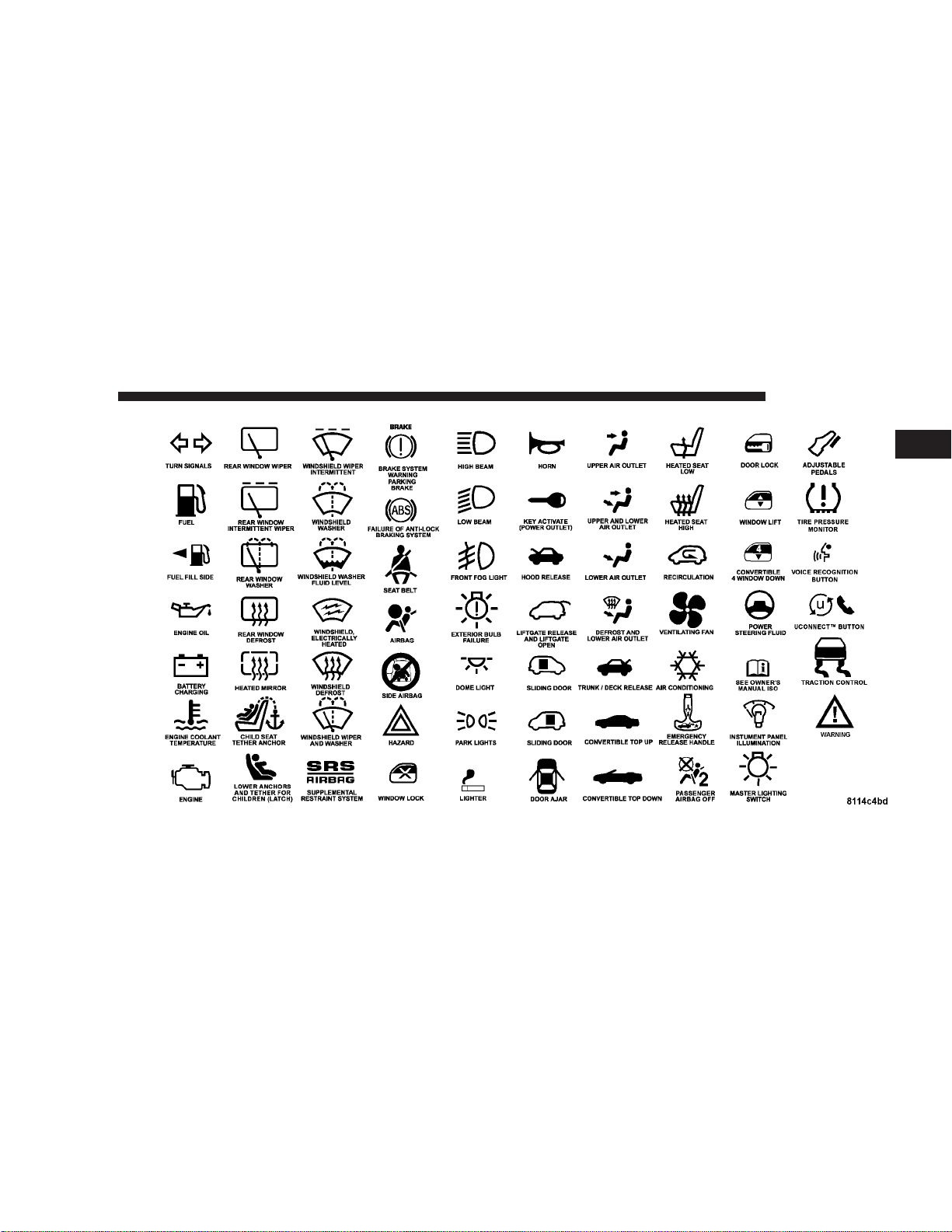
Consult the following table for a description of the
symbols that may be used on your vehicle or throughout
this owner’s manual:
Page 5
INTRODUCTION 5
1
Page 6
6 INTRODUCTION
WARNINGS AND CAUTIONS
This manual contains WARNINGS against operating
procedures which could result in an accident or bodily
injury. It also contains CAUTIONS against procedures
which could result in damage to your vehicle. If you do
not read this entire manual you may miss important
information. Observe all Warnings and Cautions.
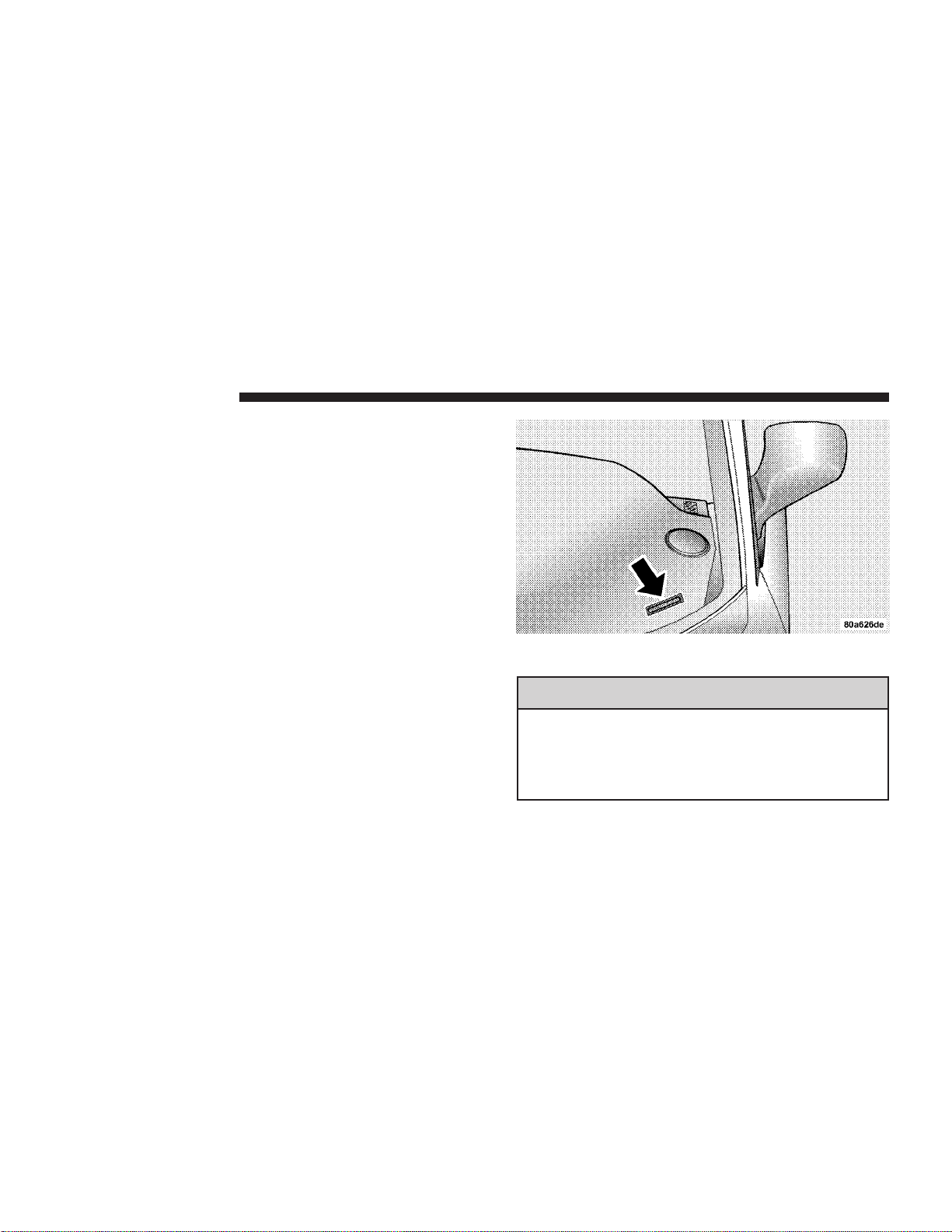
VEHICLE IDENTIFICATION NUMBER
Vehicle Identification Number (VIN) is found on a laser
etched plate, located on the left front corner of the
instrument panel, visible through the windshield. This
number also appears on the vehicle registration or title.
VEHICLE MODIFICATIONS / ALTERATIONS
WARNING!
Any modifications or alterations to this vehicle
could seriously affect its roadworthiness and safety
and may lead to an accident resulting in serious
injury or death.
Page 7

THINGS TO KNOW BEFORE STARTING YOUR VEHICLE
CONTENTS
m A Word About Your Keys
▫ Locking Doors With The Key ..............9
▫ Key-In-Ignition Reminder ................9
m Sentry Key
▫ Replacement Keys ......................10
▫ Customer Key Programming ..............11
▫ General Information ....................11
m Steering Wheel Lock
▫ To Manually Lock The Steering Wheel .......12
▫ To Release The Steering Wheel Lock .........12
m Door Locks
............................9
...........................12
.................9
.....................12
▫ Manual Door Locks .....................12
▫ Power Door Locks .....................13
▫ Automatic Door Locks ...................13
▫ Child-Protection Door Lock System
(Rear Doors) ..........................14
m Internal Emergency Trunk Lid Release
m Remote Trunk Lid Release
m Remote Keyless Entry
▫ To Unlock The Doors ...................16
▫ To Lock The Doors .....................16
▫ Horn Chirp Feature .....................16
................15
....................16
.......15
2
Page 8

8 THINGS TO KNOW BEFORE STARTING YOUR VEHICLE
▫ To Unlock The Trunk ....................17
▫ Using The Panic Alarm ..................17
▫ Programming Additional Transmitters ........17
▫ General Information ....................18
▫ Transmitter Battery Service ...............18
m Power Windows
m Occupant Restraints
........................19
.....................19
▫ Lap/Shoulder Belts .....................20
▫ Adjustable Upper Shoulder Belt Anchorage ....24
▫ Lap/Shoulder Belt Untwisting Procedure .....25
▫ Seat Belts And Pregnant Women ............26
▫ Seat Belt Extender ......................27
▫ Driver And Front Passenger Supplemental
Restraint System (SRS) - Airbags ...........27
▫ Child Restraint ........................35
▫ Transporting Pets ......................42
m Engine Break-In Recommendations
m Safety Tips
............................43
..........42
▫ Exhaust Gas ..........................43
▫ Safety Checks You Should Make Inside The
Vehicle ..............................43
▫ Periodic Safety Checks You Should Make
Outside The Vehicle ....................44
Page 9
THINGS TO KNOW BEFORE STARTING YOUR VEHICLE 9
A WORD ABOUT YOUR KEYS
The dealer that sold you your new vehicle has the key
code numbers for your vehicle locks. These numbers can
be used to order duplicate keys from your dealer. Ask
your dealer for these numbers and keep them in a safe
place.
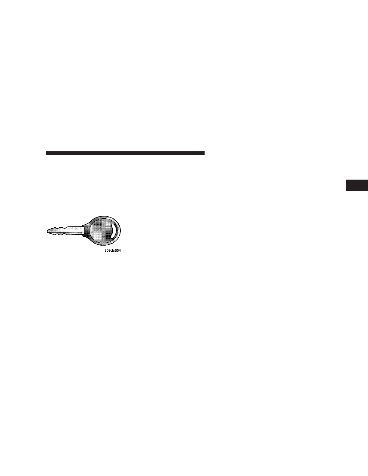
The double sided keys
may be inserted into the
locks with either side up.
Locking Doors With The Key
You can insert the key with either side up. To lock the
door, turn the key rearward. To unlock the door, turn the
key forward. See Section 7, Body Mechanism Lubrication
of this manual for external lock lubrication.
Key-In-Ignition Reminder
Opening the driver’s door when the key is in the ignition
switch, sounds a signal to remind you to remove the key.
NOTE:
ignition, the power door locks will not lock via the
interior door lock switch.
SENTRY KEY
The Sentry Key Immobilizer System prevents unauthorized operation of the vehicle by disabling the engine.
The system will shut the engine off after 2 seconds of
running if an invalid key is used to start the vehicle. This
system utilizes ignition keys which have an electronic
chip (transponder) embedded into them. Only keys that
have been programmed to the vehicle can be used to start
and operate the vehicle.
The Sentry Key Immobilizer System does not need to be
armed or activated. Operation of the system is automatic
regardless of whether or not the vehicle is locked or
unlocked. During normal operation, the Theft Alarm/
Immobilizer Light will come on for three (3) seconds
With the driver’s door open, and the key in the
2
Page 10

10 THINGS TO KNOW BEFORE STARTING YOUR VEHICLE
immediately after the ignition switch is turned on for a
bulb check. Afterwards, if the bulb remains on, this
indicates a problem with the electronics.
If the bulb begins to flash after the bulb check, this
indicates that an invalid key has been used to start the
vehicle. Both of these conditions will result in the engine
being shut off after two (2) seconds of running.
Keep in mind that a key which has not been programmed
is also considered an invalid key even if it is cut to fit the
ignition lock cylinder for that vehicle.
If the Theft Alarm/Immobilizer Light comes on during
normal vehicle operation (vehicle has been running for
longer than 10 seconds), a fault has been detected in the
electronics and the vehicle should be serviced as soon as
possible.
NOTE:
•
The Sentry Key Immobilizer System is not compatible
with remote starting systems. Use of these systems
may result in vehicle starting problems and loss of
security protection.
•
Exxon/Mobil Speed Pass,™ additional Sentry Keys, or
any other transponder equipped components on the
same keychain will not
cause a key-related (tran-
sponder) fault unless the additional part is physi-
cally held against the ignition key being used
when starting the vehicle. Cell phones, pagers, or
other RF electronics will not cause interference with
this system.
All of the keys provided with your new vehicle have
been programmed to the vehicle electronics.
Replacement Keys
NOTE:
Only keys that have been programmed to the
vehicle electronics can be used to start the vehicle. Once
a Sentry Key has been programmed to a vehicle, it can
not be programmed to any other vehicle.
At the time of purchase, the original owner is provided
with a four digit PIN number. This number is required
for dealer replacement of keys. Duplication of keys may
be performed at an authorized dealer or by using the
Customer Key Programming procedure. This procedure
Page 11

THINGS TO KNOW BEFORE STARTING YOUR VEHICLE 11
consists of programming a blank key to the vehicle
electronics. A blank key is one which has never been
programmed.
NOTE:
System serviced, bring all vehicle keys with you to the
dealer.
Customer Key Programming
You can program new keys to the system if you have two
valid sentry keys by doing the following:
1. Cut the additional Sentry Key Transponder blank(s) to
match the ignition switch lock cylinder key code.
2. Insert the first valid key into the ignition switch and
turn the ignition switch ON for at least 3 seconds but no
longer than 15 seconds. Turn the ignition switch OFF and
remove the first key.
3. Insert the second valid key and turn the ignition
switch ON within 15 seconds. After ten seconds a chime
will sound and the Theft Alarm Light will begin to flash.
Turn the ignition switch OFF and remove the second key.
When having the Sentry Key Immobilizer
4. Insert a blank Sentry Key into the ignition switch and
turn the ignition switch ON within 60 seconds. After 10
seconds a single chime will sound. The Theft Alarm Light
will stop flashing, turn on for 3 seconds; then turn off.
The new Sentry Key has been programmed. Repeat this
process to program up to a total of 8 keys.
General Information
The Sentry Key system complies with FCC rules part 15
and with RSS-210 of Industry Canada. Operation is
subject to the following conditions:
•
This device may not cause harmful interference.
•
This device must accept any interference that may be
received, including interference that may cause undesired operation.
2
Page 12

12 THINGS TO KNOW BEFORE STARTING YOUR VEHICLE
STEERING WHEEL LOCK
Your vehicle is equipped with a passive steering wheel
lock. This lock prevents steering the vehicle without the
ignition key. If the steering wheel is rotated no more than
1/2 turn in either direction and the key is not in the
ignition switch, the steering wheel will lock.
To manually lock the steering wheel:
With the engine running, rotate the steering wheel 1/2
turn, turn off the engine and remove the key. Turn the
steering wheel slightly in either direction until the lock
engages.
To release the steering wheel lock:
Insert the key in the ignition switch and start the engine.
If the key is difficult to turn, rotate the wheel slightly to
the right or left to disengage the lock.
NOTE:
If you turned the wheel to the right to engage
the lock, you must turn the wheel slightly to the right to
disengage it. If you turned the wheel to the left to engage
the lock, turn the wheel slightly to the left to disengage it.
An unlocked car is an invitation to thieves. Always
remove the key from the ignition and lock all the doors
when leaving the vehicle unattended.
DOOR LOCKS
Manual Door Locks
All doors are equipped with a rocker-type interior door
lock. To lock a door when leaving your vehicle, press the
rocker switch to the LOCK position and close the door.
NOTE:
To avoid accidentally locking your keys in the
vehicle, make sure you have them with you before
closing any door.
WARNING!
For personal security, and safety in the event of an
accident, lock the vehicle doors as you drive as well
as when you park and leave the vehicle.
Page 13
THINGS TO KNOW BEFORE STARTING YOUR VEHICLE 13
WARNING!
When leaving the vehicle always remove the key
from the ignition lock, and lock your vehicle. Do not
leave children unattended in the vehicle, or with
access to an unlocked vehicle. Unsupervised use of
vehicle equipment may cause severe personal injuries and death.
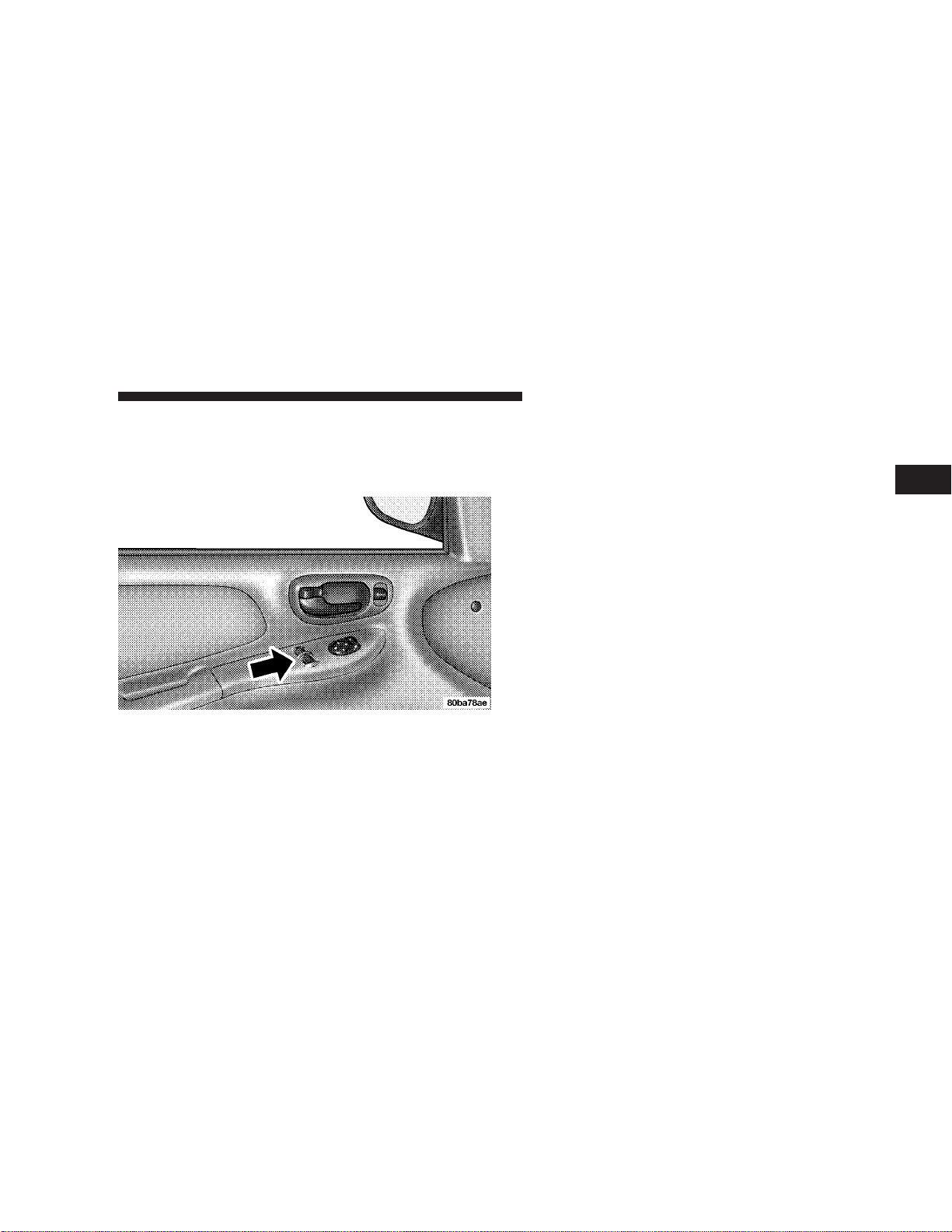
Power Door Locks
A power door lock switch is on each front door panel.
Press this switch to lock or unlock the doors.
Automatic Door Locks
The doors will lock automatically if:
1. all doors are closed,
2. vehicle speed is above 15 mph (24 km/h),
3. the accelerator pedal is depressed.
The Automatic Door Locks can be enabled or disabled by
performing the following procedure:
1. Close all doors and place the key in the ignition.
2. Cycle the ignition switch ON/OFF rapidly four times
ending in the Off position.
3. Depress the power door lock switch to LOCK.
4. A single chime will indicate the completion of the
programming.
2
Page 14
14 THINGS TO KNOW BEFORE STARTING YOUR VEHICLE
Child-Protection Door Lock System (Rear Doors)
To provide a safer environment for children riding in the
rear seat, the rear doors of your vehicle have the childprotection door lock system.
To use the system, open each rear door and slide the
control UP to engage the locks and DOWN to disengage
the child-protection locks. When the system on a door is
engaged, that door can only be opened by using the
outside door handle even if the inside door lock is in the
unlocked position.
WARNING!
Avoid trapping anyone in a vehicle in a collision.
Remember that the rear doors can only be opened
from the outside when the child protection locks are
engaged.
NOTE:
move the door lock rocker switch to the UNLOCK
position, roll down the window and open the door with
the outside door handle.
For emergency exit with the system engaged,
Page 15
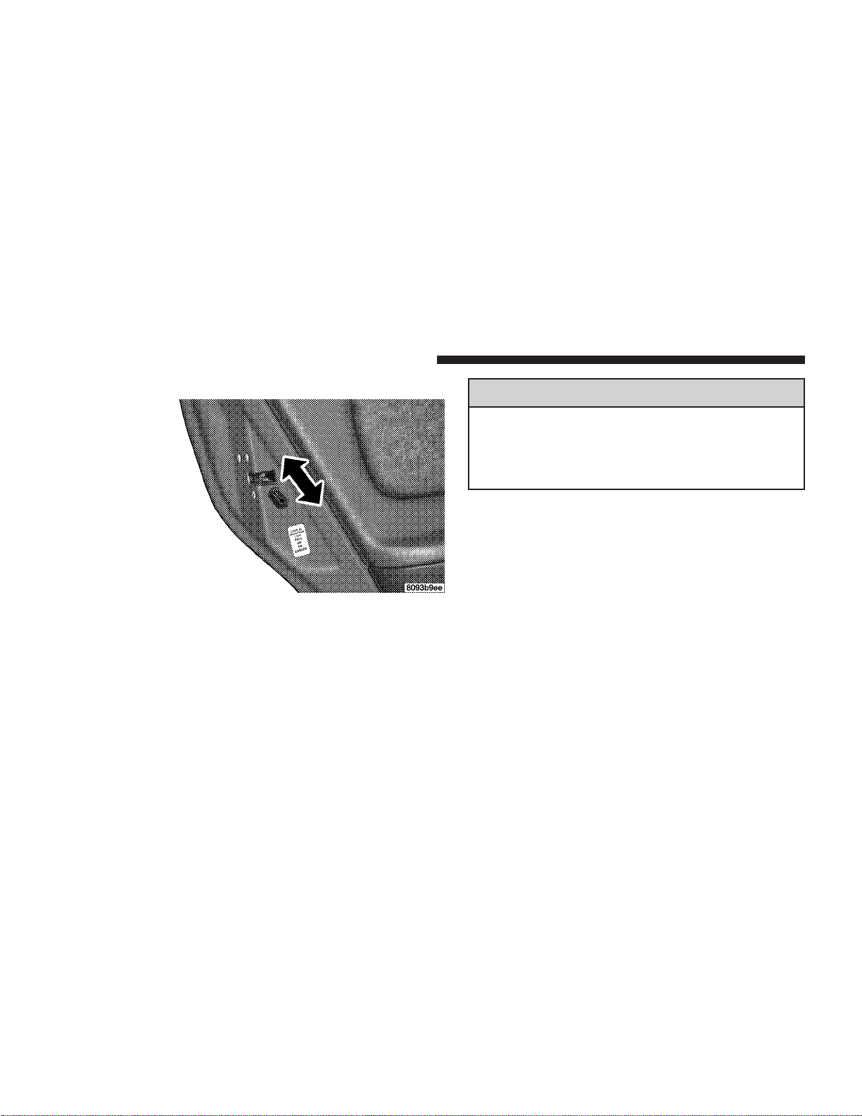
INTERNAL EMERGENCY TRUNK LID RELEASE
THINGS TO KNOW BEFORE STARTING YOUR VEHICLE 15
WARNING!
Do not allow children to have access to the trunk,
either by climbing into the trunk from outside, or
through the inside of the vehicle. Always close the
trunk lid when your vehicle is unattended. Once in
the trunk, young children may not be able to escape,
even if they entered through the rear seat. If trapped
in the trunk, children can die from suffocation or
heat stroke.
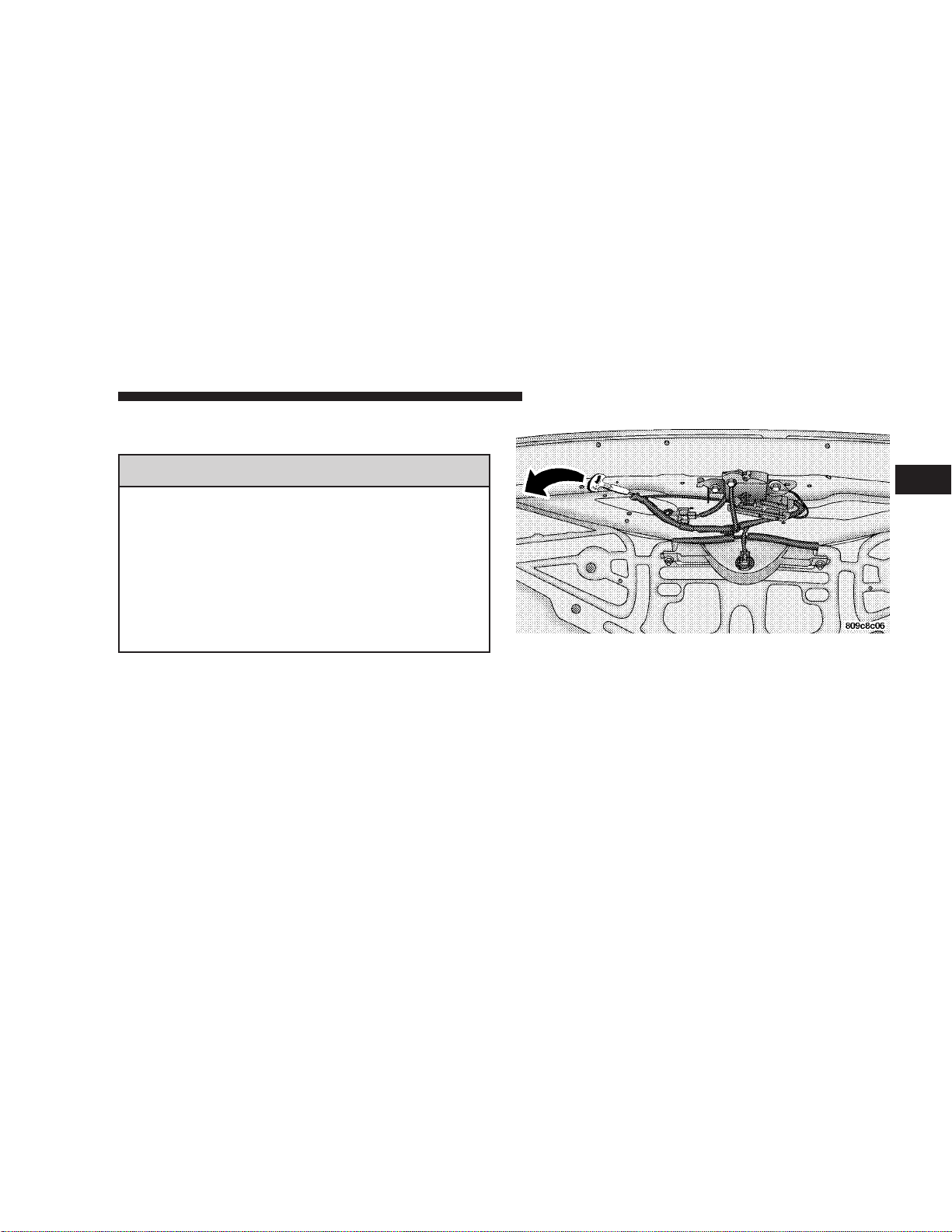
As a security measure, a Trunk Internal Emergency
Release lever is built into the trunk latching mechanism.
In the event of an individual being locked inside the
trunk, the trunk can be simply opened by pulling on the
glow-in-the-dark lever attached to the trunk latching
mechanism. See picture below.
REMOTE TRUNK LID RELEASE
You can open the trunk from inside the vehicle by
pressing a switch located inside the glove compartment.
NOTE:
with the ignition switch in all positions. The remote trunk
release will not operate above 5 mph.
The remote trunk release feature will operate
2
Page 16
16 THINGS TO KNOW BEFORE STARTING YOUR VEHICLE
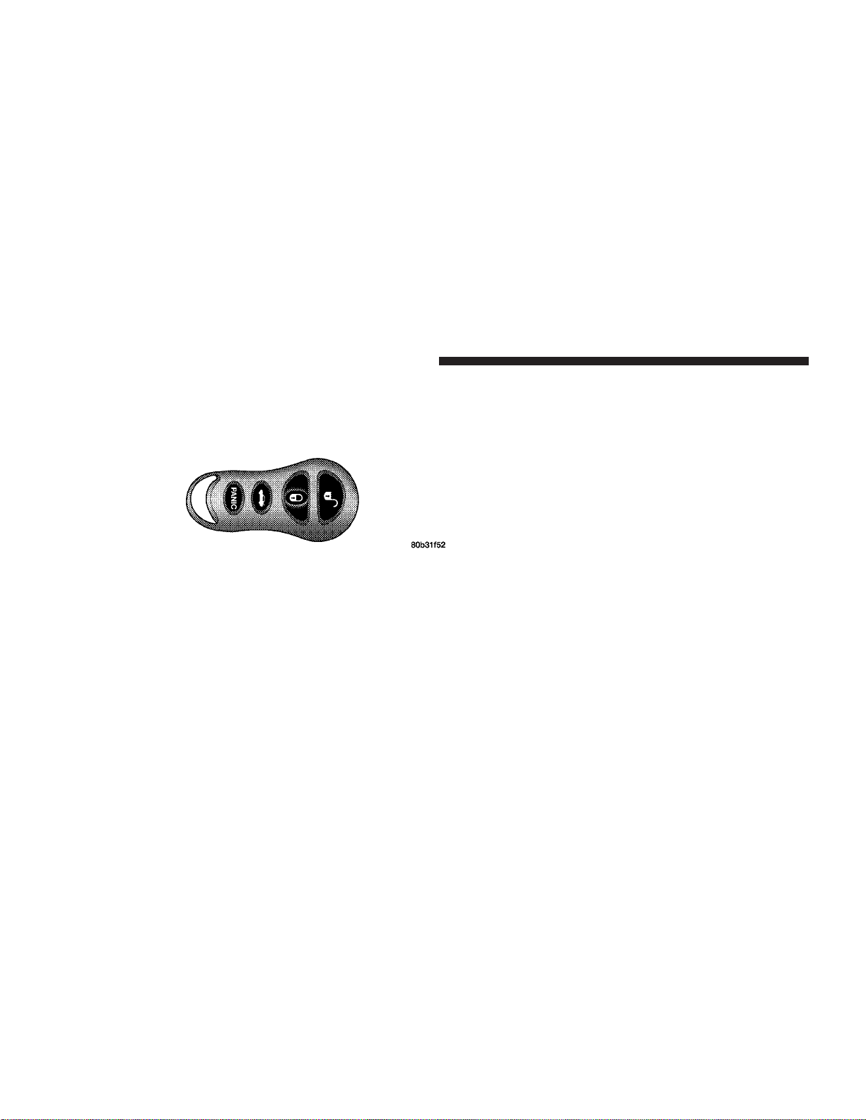
REMOTE KEYLESS ENTRY
This system allows you to lock or unlock the doors and
trunk or activate the panic alarm from distances up to
about 23 feet (7 meters) using a hand held transmitter.
NOTE:
A slight delay of up to two seconds can occur
before the doors or trunk will unlock.
To Unlock the Doors
Press and release the UNLOCK button once to unlock the
driver’s door. Press the button twice within 5 seconds to
unlock all doors. The interior lights also come on and
remain on for about 30 seconds when you unlock the
doors.
NOTE:
You may turn off this feature and unlock all
doors with one press of the button by following the
procedure shown in the Central Locking/Unlocking
paragraph.
To Lock the Doors
Press and release the LOCK button to lock all doors. The
park/lamps will flash and the horn will chirp to acknowledge the signal.
Horn Chirp Feature
The horn chirp that signals that the doors have been
locked can be toggled on or off by using the following
procedure:
1. Insert the ignition key and turn the switch to the
ON/RUN position.
2. Press and hold the UNLOCK button on the transmitter
for 4 to 10 seconds.
3. Continue to hold the UNLOCK button and press the
LOCK button.
4. Release both buttons.
A chime will sound to signify that the feature has been
successfully completed.
Page 17

THINGS TO KNOW BEFORE STARTING YOUR VEHICLE 17
To Unlock the Trunk
Press the TRUNK button on the transmitter twice to
unlock the trunk.
NOTE:
before the trunk unlatches.
Using The Panic Alarm
To turn on the panic alarm feature, press and release the
PANIC button. When the panic alarm is on the headlights
and park/lamps will flash, the horn will pulse on and off
and the interior lights will turn on.
The panic alarm will stay on for 3 minutes unless you
press the PANIC button a second time, or until vehicle
speed reaches 15 mph (24 km/h).
NOTE:
the PANIC button a second time, you may have to be
closer to the vehicle due to the radio frequency noises of
the system.
A slight delay of up to two seconds can occur
When you turn off the panic alarm by pressing
Programming Additional Transmitters
Up to four transmitters can be programmed to your
vehicle. Your new vehicle was shipped with two transmitters. See your dealer for additional transmitters.
Additional transmitters can be programmed to the system by using the following procedure:
1. Insert the key into the ignition and turn the switch to
the RUN position.
2. Press and hold the UNLOCK button on the transmitter
for between four and ten seconds.
3. Continue to hold the UNLOCK button and press the
PANIC button. A chime will sound to indicate that the
transmitter programming mode has been entered.
4. Press a button on all transmitters to be programmed to
the system, including any previously programmed transmitters. A chime will sound when each transmitter has
been programmed.
5. Turn the ignition switch off to exit the transmitter
programming mode.
2
Page 18
18 THINGS TO KNOW BEFORE STARTING YOUR VEHICLE
General Information
This device complies with FCC rules part 15. Operation is
subject to the following two conditions: (1) This device
may not cause harmful interference and (2) This device
must accept any interference that may be received, including interference that may cause undesired operation.
If your transmitter fails to operate from a normal distance, check for these two conditions.
1. Weak batteries in transmitter. The expected life of
batteries is from one to two years.
2. Closeness to a radio transmitter such as a radio station
tower, airport transmitter, and some mobile or CB radios.
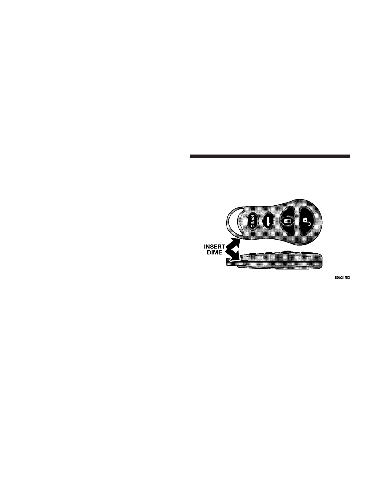
Transmitter Battery Service
The recommended replacement battery is 2016 or its
equivalent.
NOTE:
Do not touch the battery terminals that are on
the back housing or the printed circuit board.
1. With the transmitter buttons facing down, use a thin
coin or similar object to pry the two halves of the
transmitter apart. Make sure not to damage the rubber
gasket during removal.
2. Remove and replace the batteries. Avoid touching the
new batteries with your fingers. Skin oils may cause
battery deterioration. If you touch a battery, clean it with
rubbing alcohol.
3. To reassemble the transmitter case, snap two halves
together. Make sure there is an even gap between the two
halves. Test transmitter operation.
Page 19
THINGS TO KNOW BEFORE STARTING YOUR VEHICLE 19
POWER WINDOWS
The window switches on the driver’s door panel control
both front windows. The switch on the passenger’s door
panel controls the passenger’s window.
OCCUPANT RESTRAINTS
Some of the most important safety features in your
vehicle are the restraint systems. These include the front
and rear seat belts for the driver and all passengers, front
airbags for both the driver and front passenger and side
airbags for both the driver and front passenger. If you
will be carrying children too small for adult-size belts,
your seat belts also can be used to hold infant and child
restraint systems.
Please pay close attention to the information in this
section. It tells you how to use your restraint system
properly to keep you and your passengers as safe as
possible.
2
Page 20
20 THINGS TO KNOW BEFORE STARTING YOUR VEHICLE
WARNING!
In a collision, you and your passengers can suffer
much greater injuries if you are not properly buckled up. You can strike the interior of your vehicle or
other passengers, or you can be thrown out of the
vehicle. Always be sure you and others in your
vehicle are buckled up properly.
Buckle up even though you are an excellent driver, even
on short trips. Someone on the road may be a poor driver
and cause a collision that includes you. This can happen
far away from home or on your own street.
Research has shown that seat belts save lives, and that
they can reduce the seriousness of injuries in a collision.
Some of the worst injuries happen when people are
thrown from the vehicle. Seat belts reduce the possibility
of ejection and the risk of injury caused by striking the
inside of the vehicle. Everyone in a motor vehicle should
be belted at all times.
Lap/Shoulder Belts
All the seats in your vehicle are equipped with Lap/
Shoulder Belts.
The belt webbing retractor is designed to lock during
very sudden stops or collisions. This feature allows the
shoulder part of the belt to move freely with you under
normal conditions. But in a collision, the belt will lock
and reduce your risk of striking the inside of the vehicle
or being thrown out.
Page 21
THINGS TO KNOW BEFORE STARTING YOUR VEHICLE 21
WARNING!
•
Wearing a seat belt incorrectly is dangerous. Seat
belts are designed to go around the large bones of
your body. These are the strongest parts of your
body and can take the forces of a collision the
best.
•
Wearing your belt in the wrong place could make
your injuries in a collision much worse. You
might suffer internal injuries, or you could even
slide out of part of the belt. Follow these instructions to wear your seat belt safely and to keep
your passengers safe, too.
•
Two people should never be belted into a single
seat belt. People belted together can crash into one
another in an accident, hurting one another badly.
Never use a lap/shoulder belt or lap belt for more
than one person, no matter what their size.
Lap/Shoulder Belt Operating Instructions
1. Enter the vehicle and close the door. Sit back and
adjust the seat.
2
Page 22
22 THINGS TO KNOW BEFORE STARTING YOUR VEHICLE
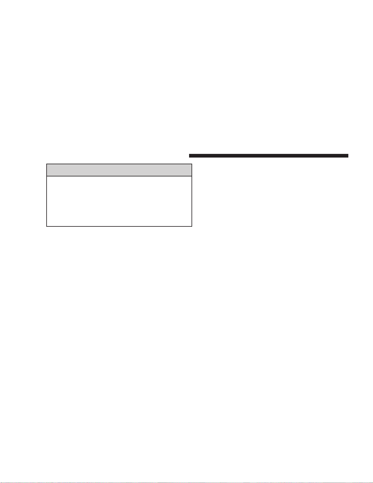
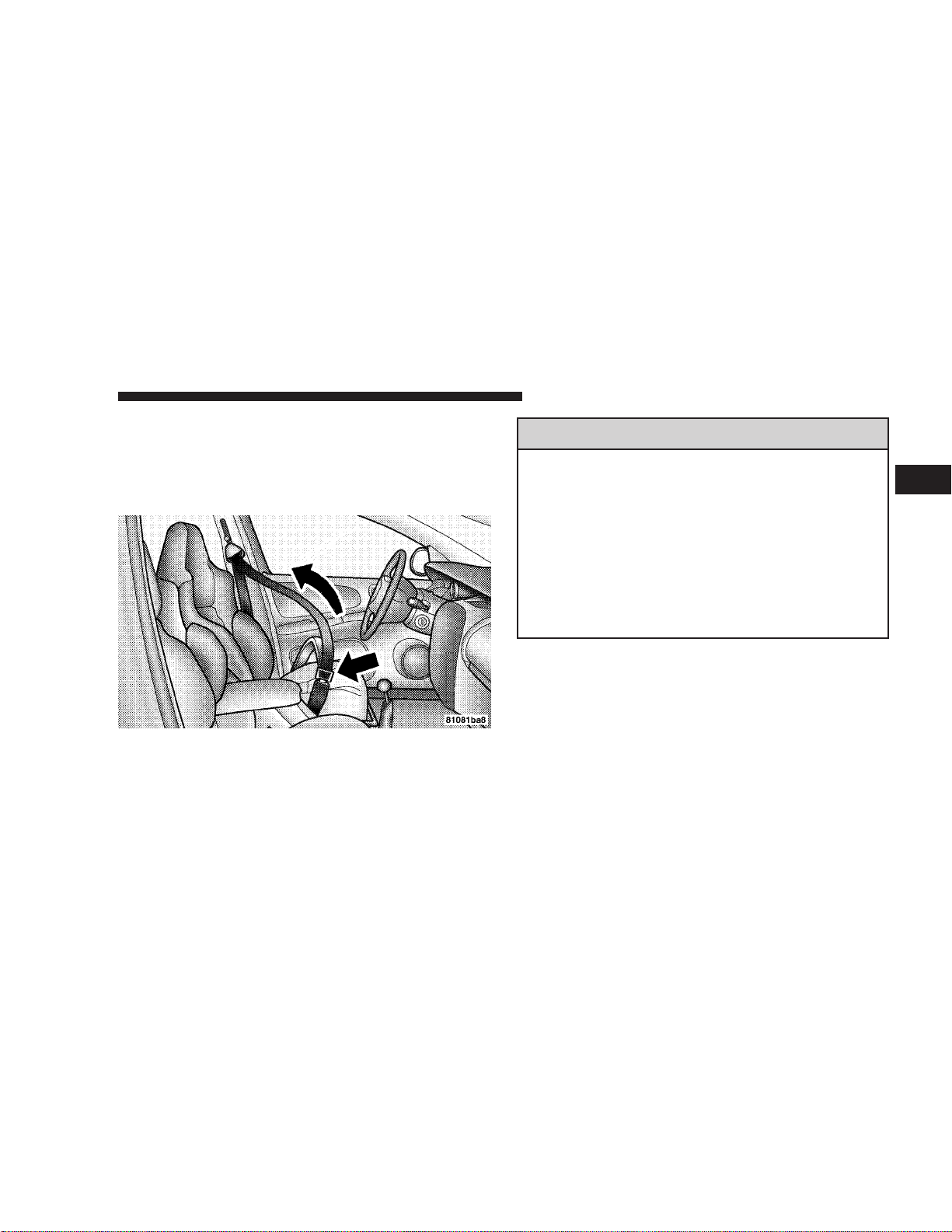
2. The seat belt latch plate is above the back of the front
seat, next to your arm in the rear seat. Grasp the latch
plate and pull out the belt. Slide the latch plate up the
webbing as far as necessary to allow the belt to go around
your lap.
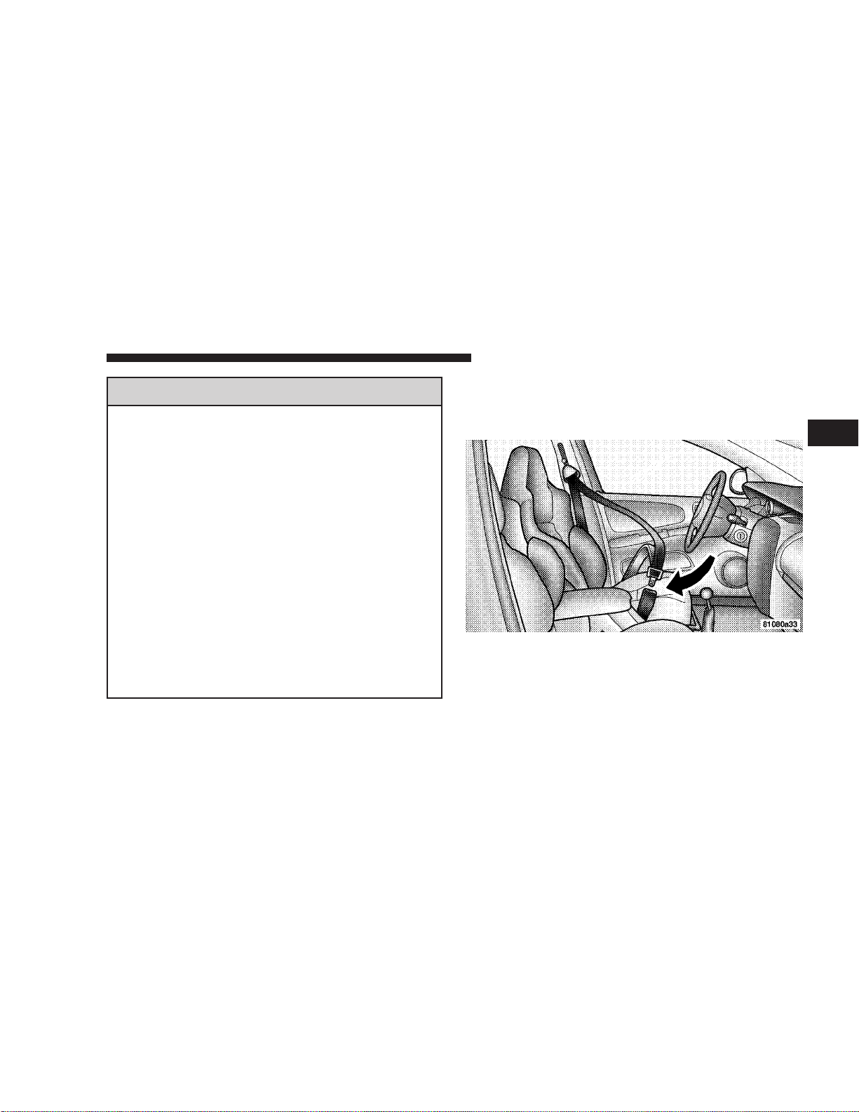
3. When the belt is long enough to fit, insert the latch
plate into the buckle until you hear a “click.”
WARNING!
•
A belt that is buckled into the wrong buckle will
not protect you properly. The lap portion could ride
too high on your body, possibly causing internal
injuries. Always buckle your belt into the buckle
nearest you.
•
A belt that is too loose will not protect you as well.
In a sudden stop you could move too far forward,
increasing the possibility of injury. Wear your seat
belt snugly.
•
A belt that is worn under your arm is very dangerous. Your body could strike the inside surfaces of the
vehicle in a collision, increasing head and neck
injury. A belt worn under the arm can cause internal
injuries. Ribs aren’t as strong as shoulder bones.
Wear the belt over your shoulder so that your strongest bones will take the force in a collision.
•
A shoulder belt placed behind will not protect you
from injury during a collision. You are more likely to
hit your head in a collision if you do not wear your
shoulder belt. The lap and shoulder belt are meant to
be used together.
Page 23
THINGS TO KNOW BEFORE STARTING YOUR VEHICLE 23
4. Position the lap belt across your thighs, below your
abdomen. To remove slack in the lap belt portion, pull up
on the shoulder belt. To loosen the lap belt if it is too tight,
tilt the latch plate and pull on the lap belt. A snug belt
reduces the risk of sliding under the belt in a collision.
WARNING!
• A lap belt worn too high can increase the risk of
internal injury in a collision. The belt forces won’t
be at the strong hip and pelvic bones, but across your
abdomen. Always wear the lap belt as low as possible and keep it snug.
• Atwisted belt can’t do its job as well. In a collision
it could even cut into you. Be sure the belt is straight.
If you can’t straighten a belt in your vehicle, take it
to your dealer and have it fixed.
5. Position the shoulder belt on your chest so that it is
comfortable and not resting on your neck. The retractor
will withdraw any slack in the belt.
6. To release the belt, push the red button on the buckle.
The belt will automatically retract to its stowed position.
If necessary, slide the latch plate down the webbing to
allow the belt to retract fully.
2
Page 24
24 THINGS TO KNOW BEFORE STARTING YOUR VEHICLE
WARNING!
A frayed or torn belt could rip apart in a collision
and leave you with no protection. Inspect the belt
system periodically, checking for cuts, frays, or loose
parts. Damaged parts must be replaced immediately.
Do not disassemble or modify the system. Front seat
belt assemblies must be replaced after a collision.
Rear seat belt assemblies must be replaced after a
collision if they have been damaged (bent retractor,
torn webbing, etc.).
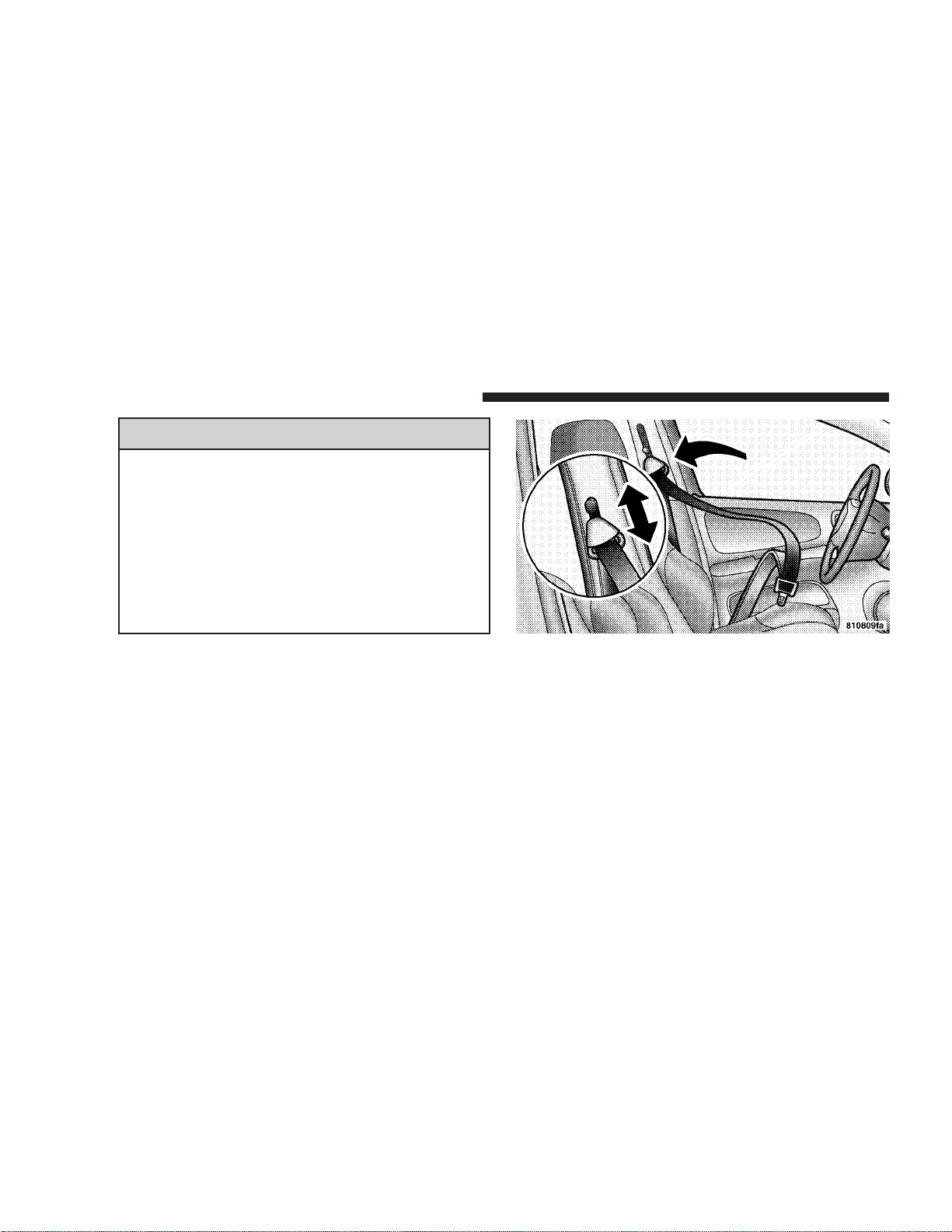
Adjustable Upper Shoulder Belt Anchorage
In the driver and front passenger seats, the shoulder belt
can be adjusted upward or downward to position the belt
away from your neck. Push up or down on the anchorage
button to release the anchorage, and then move it up or
down to the position that serves you best.
As a guide, if you are shorter than average, you will
prefer a lower position, and if you are taller than average,
you’ll prefer a higher position. When you release the
anchorage, try to move it up or down to make sure that
it is locked in position.
Page 25
THINGS TO KNOW BEFORE STARTING YOUR VEHICLE 25
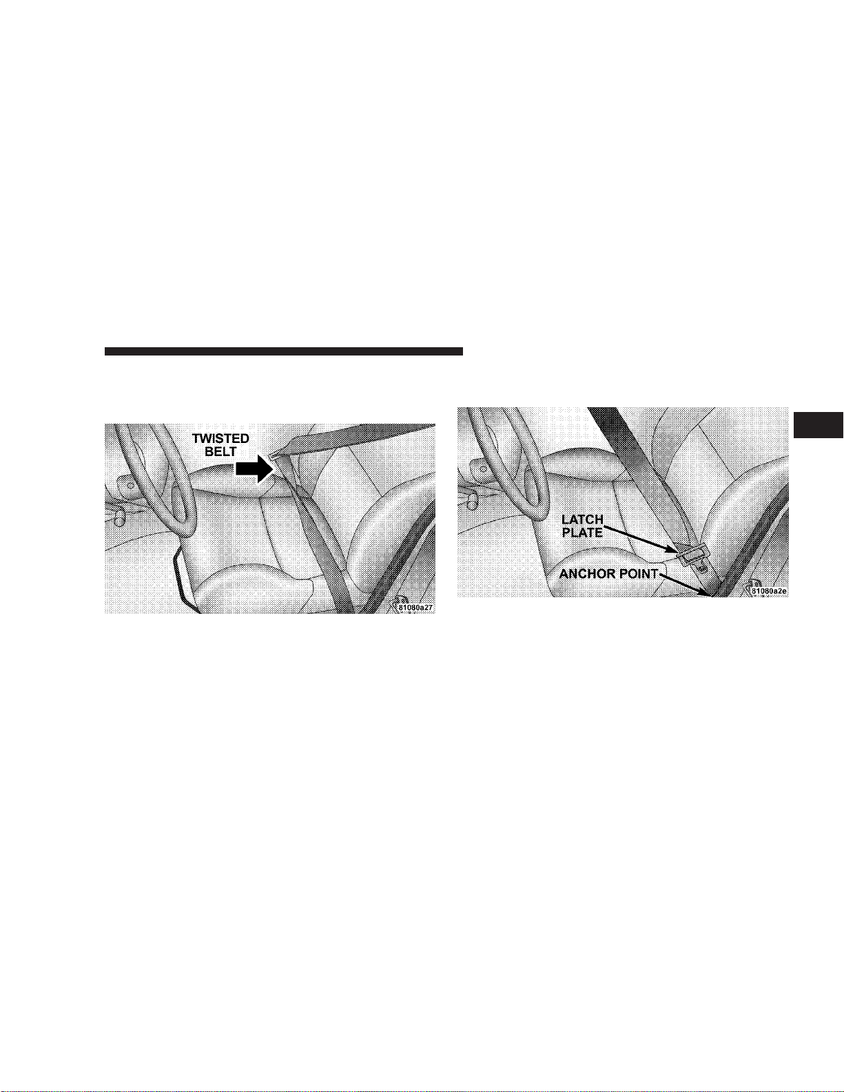
Lap/Shoulder Belt Untwisting Procedure
Use the following procedure to untwist a twisted lap/
shoulder belt.
1. Position the latch plate as close as possible to the
anchor point.
2
Page 26
26 THINGS TO KNOW BEFORE STARTING YOUR VEHICLE
2. At about 6 to 12 inches above the latch plate, grasp and
twist the belt webbing 180° to create a fold that begins
immediately above the latch plate.
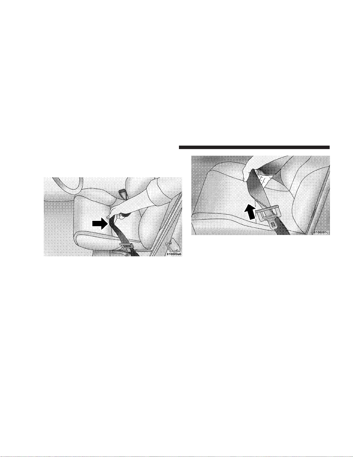
4. Continue to slide the latch plate up until it clears the
folded webbing.
3. Slide the latch plate upward over the folded webbing.
The folded webbing must enter the slot at the top of the
latch plate.
Seat Belts And Pregnant Women
We recommend that pregnant women use the seat belts
throughout their pregnancy. Keeping the mother safe is
the best way to keep the baby safe.
Pregnant women should wear the lap part of the belt
across the thighs and as snug across the hips as possible.
Page 27
THINGS TO KNOW BEFORE STARTING YOUR VEHICLE 27
Keep the belt low so that it does not come across the
abdomen. That way the strong bones of the hips will take
the force if there is a collision.
Seat Belt Extender
If a seat belt is too short, even when fully extended and
when the adjustable upper shoulder belt anchorage (if
equipped) is in its lowest position, your dealer can
provide you with a seat belt extender. This extender
should be used only if the existing belt is not long
enough. When it is not required, remove the extender
and store it.
WARNING!
Using a seat belt extender when not needed can
increase the risk of injury in a collision. Only use
when the seat belt is not long enough when it is
worn low and snug, and in the recommended seating
positions. Remove and store the extender when not
needed.
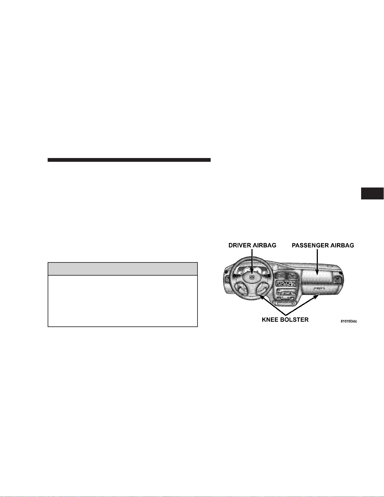
Driver and Front Passenger Supplemental
Restraint System (SRS) - Airbags
This vehicle has front airbags for both the driver and
front passenger as a supplement to the seat belt restraint
systems. The driver’s front airbag is mounted in the
center of the steering wheel. The passenger’s front airbag
is mounted in the instrument panel, above the glove
compartment. The words SRS AIRBAG are embossed on
the airbag covers.
NOTE:
regulations that allow less forceful deployment.
The front airbags are certified to the Federal
2
Page 28
28 THINGS TO KNOW BEFORE STARTING YOUR VEHICLE
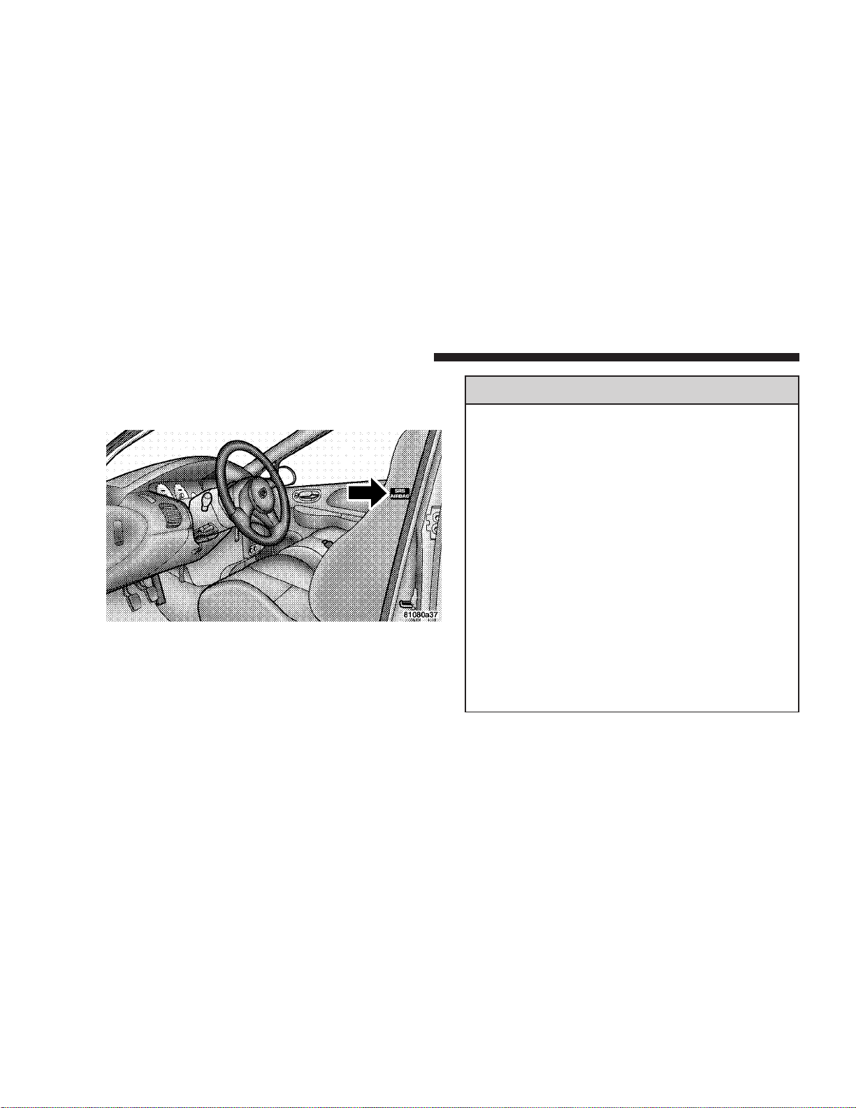
If the vehicle is equipped with side airbags, they are
located inside the driver and front passenger seats, and
their covers are also labeled SRS AIRBAG.
NOTE:
Airbag covers may not be obvious in the
interior trim; but they will open to allow airbag deployment.
WARNING!
•
Do not put anything on or around the front airbag
covers or attempt to manually open them. You
may damage the airbags and you could be injured
because the airbags are not there to protect you.
These protective covers for the airbag cushions are
designed to open only when the airbags are inflating.
•
If your vehicle is equipped with side airbags, do
not use accessory seat covers or place objects
between you and the side airbags; the performance could be adversely affected and/or objects
could be pushed into you, causing serious injury.
•
If your vehicle is equipped with side airbags, do
not attach cup holders or any other objects on or
around the door. The inflating side airbag could
drive the objects into occupants, causing serious
injury.
Page 29

THINGS TO KNOW BEFORE STARTING YOUR VEHICLE 29
Airbags inflate in moderate to high speed impacts. Along
with the seat belts, front airbags work with the instrument panel knee bolsters to provide improved protection
for the driver and front passenger. Side airbags also work
with seat belts to improve occupant protection.
The seat belts are designed to protect you in many types
of collisions. The front airbags deploy in moderate to
severe frontal collisions. If your vehicle is equipped, the
side airbag on the crash side of the vehicle is triggered in
moderate to severe side collisions. In certain types of
collisions, both the front and side airbags may be triggered. But even in collisions where the airbags work, you
need the seat belts to keep you in the right position for
the airbags to protect you properly.
Here are some simple steps you can take to minimize the
risk of harm from a deploying airbag.
1. Children 12 years old and under should always ride
buckled up in a rear seat.
Infants in rear facing child restraints (designed for children up to 20 lbs (9 kg) and less than one year old) should
NEVER ride in the front seat of a vehicle with a passenger front airbag. An airbag deployment could cause
severe injury or death to infants in that position.
Children that are not big enough to properly wear the
vehicle’s seat belt (see section on Child Restraint) should
be secured in the rear seat in child restraints or beltpositioning booster seats.
Older children who do not use child restraints or beltpositioning booster seats should ride properly buckled
up in the rear seat. Never allow children to slide the
shoulder belt behind them or under their arm.
2
Page 30

30 THINGS TO KNOW BEFORE STARTING YOUR VEHICLE
If a child from 1 to 12 years old must ride in the front
passenger seat because the vehicle is crowded, move the
seat as far back as possible, and use the proper child
restraint. See the section on Child Restraint.
You should read the instructions provided with your
child restraint to make sure that you are using it properly.
2. All occupants should wear their lap and shoulder
belts properly.
3. The driver and front passenger seats should be
moved back as far as practical to allow the front airbags
room to inflate.
4. If your vehicle has side airbags, do not lean against
the door, airbags will inflate forcefully into the space
between you and the door.
WARNING!
•
Relying on the airbags alone could lead to more
severe injuries in a collision. The airbags work
with your seat belt to restrain you properly. In
some collisions the airbags won’t deploy at all.
Always wear your seat belts even though you
have airbags.
•
Being too close to the steering wheel or instrument panel during airbag deployment could cause
serious injury. Airbags need room to inflate. Sit
back, comfortably extending your arms to reach
the steering wheel or instrument panel.
•
If the vehicle has side airbags, they also need
room to inflate. Do not lean against the door. Sit
upright in the center of the seat.
Page 31

THINGS TO KNOW BEFORE STARTING YOUR VEHICLE 31
Airbag System Components
The front airbag system consists of the following:
•
Airbag Control Module (ACM)
•
AIRBAG Readiness Light
•
Driver Airbag
•
Passenger Airbag
•
Steering Wheel and Column
•
Instrument Panel
•
Crash Sensor
•
Interconnecting Wiring
•
Knee Impact Bolsters
The side airbag system, if equipped, consists of the
following:
•
AIRBAG Readiness Light (shared with the front airbag
system)
•
Side Airbag in the Driver’s Seat
•
Side Airbag in the Passenger’s Seat
•
Right and Left Side Impact Airbag Control Modules
(SIACM)
•
Interconnecting Wiring
How The Airbag System Works
Front Airbag System
•
The front Airbag Control Module determines if a
frontal collision is severe enough to require the airbags
to inflate.
•
The Airbag Control Module is not designed to detect
side, roll over, or rear collisions.
•
The Airbag Control Module also monitors the readiness of the electronic parts of the system whenever the
ignition switch is in the START or ON/RUN positions.
These include all of the items listed above except the
knee bolsters, the instrument panel, and the steering
wheel and column. If the key is in the OFF position, in
the ACC position, or not in the ignition switch, the
airbags are not on and will not inflate.
2
Page 32

32 THINGS TO KNOW BEFORE STARTING YOUR VEHICLE
•
The Airbag Control Module also turns on the AIRBAG
light in the instrument panel for 6 to 8 seconds when
the ignition switch is first turned to ON/RUN, then
turns the light off. If it detects a malfunction in any
part of the system, it turns on the light either momentarily or continuously.
WARNING!
Ignoring the AIRBAG light in your instrument panel
could mean you won’t have the airbags to protect
you in a collision. If the light does not come on, stays
on after you start the vehicle, or if it comes on as you
drive, have the airbag system checked right away.
•
When the Airbag Control Module detects a collision
requiring the airbags, it signals the inflator units. A
large quantity of nontoxic gas is generated to inflate
the airbags. The airbag covers separate and fold out of
the way as the airbags inflate to their full size. The
airbags fully inflate in about 50 milliseconds. This is
only about half of the time it takes you to blink your
eyes. The airbags then quickly deflate while helping to
restrain the driver and front passenger. The driver’s
front airbag gas is vented through the airbag material
towards the instrument panel. The passenger’s front
airbag gas is vented through vent holes in the sides of
the airbag. In this way the airbags do not interfere with
your control of the vehicle.
Page 33

THINGS TO KNOW BEFORE STARTING YOUR VEHICLE 33
•
The knee impact bolsters help protect the knees and
position you for the best interaction with the front
airbag.
If A Deployment Occurs
The airbag system is designed to deploy when the Airbag
Control Module detects a moderate-to-severe frontal
collision, to help restrain the driver and front passenger,
and then to immediately deflate.
NOTE:
need airbag protection will not activate the system. This
does not mean something is wrong with the airbag
system.
If you do have a collision which deploys the airbags, any
or all of the following may occur:
•
A frontal collision that is not severe enough to
The nylon airbag material may sometimes cause abrasions and/or skin reddening to the driver and front
passenger as the airbags deploy and unfold. The
abrasions are similar to friction rope burns or those
you might get sliding along a carpet or gymnasium
floor. They are not caused by contact with chemicals.
They are not permanent and normally heal quickly.
However, if you have not healed significantly within a
few days, or if you have any blistering, see your doctor
immediately.
•
As the airbags deflate you may see some smoke-like
particles. The particles are a normal by-product of the
process that generates the nontoxic gas used for airbag
inflation. These airborne particles may irritate the skin,
eyes, nose, or throat. If you have skin or eye irritation,
rinse the area with cool water. For nose or throat
irritation, move to fresh air. If the irritation continues,
see your doctor. If these particles settle on your
clothing, follow the garment manufacturer’s instructions for cleaning.
•
It is not advisable to drive your vehicle after the
airbags have deployed. If you are involved in another
collision, the airbags will not be in place to protect you.
2
Page 34

34 THINGS TO KNOW BEFORE STARTING YOUR VEHICLE
WARNING!
Deployed airbags can’t protect you in another collision. Have the airbags replaced by an authorized
dealer as soon as possible.
Side Airbag System — If Equipped
The Side Impact Airbag Control Modules determine if
•
a side collision is severe enough to require the airbag
to inflate. The Side Impact Airbag Control Modules is
not designed to detect roll over, front, or rear impacts.
•
The Side Impact Airbag Control Module monitors the
readiness of the electronic parts of the system whenever the ignition switch is in the START or ON/RUN
positions. These include all of the items listed above. If
the left or right SIACM detects a malfunction in any
part of the system, it will send a message to the frontal
ACM to turn the Airbag Light on. The Airbag Control
Module also turns on the AIRBAG light in the instrument panel for 6 to 8 seconds when the ignition switch
is first turned on as a diagnostic or system check, then
turns the light off.
•
In moderate to severe side collisions, the side airbag
inflator on the crash side of the vehicle is triggered by
the appropriate SIACM, releasing a quantity of nontoxic gas. The inflating side airbag exits through the
seat seam into the space between the occupant and the
door. The side airbag moves at a very high speed and
with such a high force, that it could injure you if you
are not seated properly, or if items are positioned in
the area where the side airbag inflates. This especially
applies to children.
Enhanced Accident Response Time — If Equipped
If the airbags deploy after an impact and the electrical
system remains functional, vehicles equipped with
power door locks will unlock automatically. In addition,
approximately 10 seconds after the vehicle has stopped
moving, the interior lights will light until the ignition
switch is turned off.
Page 35

THINGS TO KNOW BEFORE STARTING YOUR VEHICLE 35
Maintaining Your Airbag Systems
WARNING!
•
Modifications to any part of the airbag system
could cause it to fail when you need it. You could
be injured because the airbags are not there to
protect you. Do not modify the components or
wiring, including adding any kind of badges or
stickers to the steering wheel hub trim cover or
the upper right side of the instrument panel. Do
not modify the front bumper, vehicle body structure, or frame.
•
You need proper knee impact protection in a
collision. Do not mount or locate any aftermarket
equipment on or behind the knee bolster.
•
It is dangerous to try to repair any part of the
airbag system yourself. Be sure to tell anyone who
works on your vehicle that it has airbags.
Airbag Light
You will want to have the airbags ready to inflate for your
protection in an impact. While the airbag system is
designed to be maintenance free, if any of the following
occurs, have an authorized dealer service the system
immediately:
•
The AIRBAG light does not come on or flickers during
the 6 to 8 seconds when the ignition switch is first
turned on.
•
The light remains on or flickers after the 6 to 8 second
interval.
•
The light flickers or comes on and remains on while
driving.
Child Restraint
Everyone in your vehicle needs to be buckled up at all
times — babies and children, too. Every state in the
United States and all Canadian provinces require that
small children ride in proper restraint systems. This is the
law, and you can be prosecuted for ignoring it.
2
Page 36

36 THINGS TO KNOW BEFORE STARTING YOUR VEHICLE
Children 12 years and under should ride properly buckled up in a rear seat, if available. According to crash
statistics, children are safer when properly restrained in
the rear seats, rather than in the front.
WARNING!
In a collision, an unrestrained child, even a tiny
baby, can become a missile inside the vehicle. The
force required to hold even an infant on your lap
could become so great that you could not hold the
child, no matter how strong you are. The child and
others could be badly injured. Any child riding in
your vehicle should be in a proper restraint for the
child’s size.
Infants And Small Children
There are different sizes and types of restraints for
children from newborn size to the child almost large
enough for an adult safety belt. Always check the child
seat Owner’s Manual to ensure you have the right seat
for your child. Use the restraint that is correct for your
child:
•
Safety experts recommend that children ride
rearward-facing in the vehicle until they are at least
one year old and weigh at least 20 lbs (9 kg). Two types
of child restraints can be used rearward-facing: infant
carriers and “convertible” child seats. Both types of
child restraints are held in the vehicle by the lap/
shoulder belt or the LATCH child restraint anchorage
system.
•
The infant carrier is only used rearward-facing in the
vehicle. It is recommended for children who weigh up
to about 20 lbs (9 kg). “Convertible” child seats can be
used either rearward-facing or forward-facing in the
vehicle. Convertible child seats often have a higher
weight limit in the rearward-facing direction than
infant carriers do, so they can be used rearward-facing
by children who weigh more than 20 lbs (9 kg) but are
less than one year old.
•
Rearward-facing child seats must NEVER be used in
the front seat of a vehicle with the front passenger
airbag. An airbag deployment could cause severe
injury or death to infants in this position.
Page 37

•
Children who weigh more than 20 lbs (9 kg) and who
are older than one year can ride forward-facing in the
vehicle. Forward-facing child seats and convertible
child seats used in the forward-facing direction are for
children who weigh 20 to 40 lbs (9 to 18 kg) and who
are older than one year. These child seats are also held
in the vehicle by the lap/shoulder belt or the LATCH
child restraint anchorage system.
•
The belt-positioning booster seat is for children weighing more than 40 lbs (18 kg ), but who are still too
small to fit the vehicle’s seat belts properly. If the child
cannot sit with knees bent over the vehicle’s seat
cushion while the child’s back is against the seat back;
they should use a Belt Positioning Booster Seat. The
child and booster seat are held in the vehicle by the
lap/shoulder belt. (Some booster seats are equipped
with a front shield and are held in the vehicle by the
lap portion).
NOTE:
www.seatcheck.org.
For additional information refer to
THINGS TO KNOW BEFORE STARTING YOUR VEHICLE 37
WARNING!
•
Improper installation can lead to failure of an
infant or child restraint. It could come loose in a
collision. The child could be badly injured or
killed. Follow the manufacturer’s directions exactly when installing an infant or child restraint.
•
A rearward facing infant restraint should only be
used in a rear seat. A rearward facing infant
restraint in the front seat may be struck by a
deploying passenger airbag which may cause severe or fatal injury to the infant.
Here are some tips on getting the most out of your child
restraint:
•
Before buying any restraint system, make sure that it
has a label certifying that it meets all applicable Safety
Standards. We also recommend that you make sure
that you can install the child restraint in the vehicle
where you will use it before you buy it.
2
Page 38

38 THINGS TO KNOW BEFORE STARTING YOUR VEHICLE
•
The restraint must be appropriate for your child’s
weight and height. Check the label on the restraint for
weight and height limits.
•
Carefully follow the instructions that come with the
restraint. If you install the restraint improperly, it may
not work when you need it.
The passenger seat belts are equipped with cinching latch
plates which are designed to keep the lap portion tight
around the child restraint so that it is not necessary to use
a locking clip. Pulling up on the shoulder portion of the
lap/shoulder belt will tighten the belt. The cinching latch
plate will keep the belt tight, however, any seat belt
system will loosen with time, so check the belt occasionally and pull it tight if necessary.
•
In the rear seat, you may have trouble tightening the
lap/shoulder belt on the child restraint because the
buckle or latch plate is too close to the belt path
opening on the restraint. Disconnect the latch plate
from the buckle and twist the short buckle-end belt
several times to shorten it. Insert the latch plate into
the buckle with the release button facing out.
•
If the belt still can’t be tightened, or if pulling and
pushing on the restraint loosens the belt, disconnect
the latch plate from the buckle, turn the buckle
around, and insert the latch plate into the buckle
again. If you still can’t make the child restraint secure,
try a different seating position.
•
Buckle the child into the seat according to the child
restraint manufacturer’s directions.
•
When your child restraint is not in use, secure it in the
vehicle with the seat belt or remove it from the vehicle.
Do not leave it loose in the vehicle. In a sudden stop or
collision, it could strike the occupants or seat backs
and cause serious personal injury.
LATCH —L ower Anchors and Tether for CHildren
Your vehicle’s rear seat is equipped with the child
restraint anchorage system called LATCH, which stands
for Lower Anchors and Tether for Children. The LATCH
system provides for the installation of the child restraint
without using the vehicle seat belt. All three rear seating
positions have exclusive lower anchorages. These are
round bars, located at the rear of the seat cushion where
it meets the seat back, and just visible when you lean into
Page 39

THINGS TO KNOW BEFORE STARTING YOUR VEHICLE 39
the rear seat to install the child restraint. You will easily
feel them if you run your finger along the intersection of
the surfaces. The lower strap hooks are passed over the
top of each bar, pushing aside the seat cover material.
In addition, there are tether strap anchorages
behind each rear seating position located in the
panel between the rear seat back and the rear
window — under a hinged plastic cover with
this symbol on it. (Shown to the left) In recent years, only
the tether anchorage has been provided in new vehicles.
To attach a child restraint tether strap:
1. Lift the cover over the anchor directly behind the seat
where you are placing the child restraint.
2. Route the tether strap to provide the most direct path
for the strap between the anchor and the child seat. If
your vehicle is equipped with adjustable rear head
restraints, raise the head restraint and, where possible,
route the tether strap under the head restraint and
between the two posts. If not possible, lower the head
restraint and pass the tether strap around the outboard
side of the head restraint.
2
Page 40

40 THINGS TO KNOW BEFORE STARTING YOUR VEHICLE
3. Attach the tether strap hook (A) of the child restraint to
the anchor (B) and remove slack in the tether strap
according to the child restraint manufacturer’s instructions.
WARNING!
An incorrectly anchored tether strap could lead to
increased head motion and possible injury to the
child. Use only the anchor positions directly behind
the child seat to secure a child restraint top tether
strap.
Child restraint systems having attachments designed to
connect to the lower anchorages are now available. Child
restraints having tether straps and hooks for connection
to the top tether anchorage have been available for some
time. In fact, many child restraint manufacturers will
provide add-on tether strap kits for some of their older
products. Tether anchorage kits are also available for
most older vehicles.
Because the lower anchorages are to be introduced to
passenger carrying vehicles over a period of years, child
restraint systems having attachments for those anchorages will continue to have features for installation in
vehicles using the lap or lap/shoulder belt. They will also
have tether straps, and you are urged to take advantage
of all of the available attachments provided with your
child restraint in any vehicle.
Installing the Child Restraint System
While there are LATCH anchorages at all three rear
seating positions, do not install child restraints at all three
positions at the same time. The anchorages are not
designed to restrain three child restraints at one time.
Instead, you may install one child restraint at the center
position, or two child restraints at the right and left
positions.
Page 41

THINGS TO KNOW BEFORE STARTING YOUR VEHICLE 41
WARNING!
Do not install child restraint systems equipped with
LATCH attachments at all three rear seating positions at one time. The LATCH anchorages are designed to restrain no more than two child restraints
at a time in the event of a collision.
We urge that you carefully follow the directions of the
manufacturer when installing your child restraint. Many,
but not all, restraint systems will be equipped with
separate straps on each side, with each having a hook or
connector and a means for adjusting the tension in the
strap. Forward-facing toddler restraints and some
rearward-facing infant restraints will also be equipped
with a tether strap, a hook and means for adjusting the
tension in the strap.
In general, you will first loosen the adjusters on the lower
straps and tether straps so that you can more easily attach
the hook or connector to the lower anchorages and tether
anchorages. Then tighten all three straps as you push the
child restraint rearward and downward into the seat.
Not all child restraint systems will be installed as we
have described here. Again, carefully follow the instructions that come with the child restraint system.
WARNING!
Improper installation of a child restraint to the
LATCH anchorages can lead to failure of an infant or
child restraint. The child could be badly injured or
killed. Follow the manufacturer’s directions exactly
when installing an infant or child restraint.
NOTE:
compatible, install the restraint using the vehicle seat
belts.
Children Too Large For Booster Seats
Children who are large enough to wear the shoulder belt
comfortably, and whose legs are long enough to bend
over the front of the seat when their back is against the
seat back, should use the lap/shoulder belt in a rear seat.
•
Make sure that the child is upright in the seat.
If your child restraint seat is not LATCH
2
Page 42

42 THINGS TO KNOW BEFORE STARTING YOUR VEHICLE
•
The lap portion should be low on the hips and as snug
as possible.
•
Check belt fit periodically. A child’s squirming or
slouching can move the belt out of position.
•
If the shoulder belt contacts the face or neck, move the
child closer to the center of the vehicle. Never allow a
child to put the shoulder belt under an arm or behind
their back.
ENGINE BREAK-IN RECOMMENDATIONS
The engine in your new vehicle does not require a long
break-in period.
Drive moderately during the first 300 miles (500 km).
After the initial 60 miles (100 km), speeds up to 50 or 55
mph (80 or 90 km/h) are desirable.
While cruising, brief full-throttle acceleration, within the
limits of local traffic laws, contributes to a good break-in.
Transporting Pets
Airbags deploying in the front seat could harm your pet.
An unrestrained pet will be thrown about and possibly
injured, or injure a passenger during panic braking or in
a collision.
Pets should be restrained in the rear seat in pet harnesses
or pet carriers that are secured by seat belts.
Wide open throttle acceleration in low gear can be
detrimental and should be avoided.
The crankcase oil installed in the engine at the factory is
a high quality energy conserving type lubricant. Oil
changes should be consistent with expected climate conditions under which vehicle operations will occur. The
recommended viscosity and quality grades are in Section
7 of this manual.
Do not use non-detergent or straight mineral oils. The
manufacturer recommends the use of Mobil 1t 10W30
synthetic engine oil.
Page 43

THINGS TO KNOW BEFORE STARTING YOUR VEHICLE 43
A new engine may consume some oil during its first few
thousand miles of operation. This is a normal part of the
break-in and not an indication of a problem.
SAFETY TIPS
Exhaust Gas
WARNING!
Exhaust gases can injure or kill. They contain carbon
monoxide (CO) which is colorless and odorless.
Breathing it can make you unconscious and can
eventually poison you. To avoid breathing (CO)
follow the safety tips below.
Do not run the engine in a closed garage or in confined
areas any longer than needed to move your vehicle in or
out of the area.
If it is necessary to sit in a parked vehicle with the engine
running, adjust your heating or cooling controls to force
outside air into the vehicle. Set the blower at high speed.
To avoid drawing exhaust gases into the vehicle, close the
trunk while driving. However, if for some reason it must
remain open, close all windows. Adjust the heating or
cooling system to force outside air into the vehicle. Set
the blower at high speed.
Safety Checks You Should Make Inside The
Vehicle
Seat Belts
Inspect the belt system periodically, checking for cuts,
frays and loose parts. Damaged parts must be replaced
immediately. Do not disassemble or modify the system.
Front seat belt assemblies must be replaced after a
collision. Rear seat belt assemblies must be replaced after
a collision if they have been damaged (bent retractor,torn
webbing, etc.). If there is any question regarding belt or
retractor condition, replace the belt.
2
Page 44

44 THINGS TO KNOW BEFORE STARTING YOUR VEHICLE
Airbag Light
The light should come on and remain on for 6 to
8 seconds as a bulb check when the ignition
switch is first turned to ON/RUN. If the bulb is
not lit during starting, have it replaced. If the light stays
on or comes on while driving, have the system checked
by an authorized dealer.
Defrosters
Check operation by selecting the defrost mode and place
the blower control on high speed. You should be able to
feel the air directed against the windshield.
Periodic Safety Checks You Should Make Outside
The Vehicle
Tires
Examine tires for excessive tread wear or uneven wear
patterns. Check for stones, nails, glass, or other objects
lodged in the tread. Inspect for tread cuts or sidewall
cracks. Check wheel nuts for tightness, and tires (including spare) for proper pressure.
Lights
Have someone observe the operation of exterior lights
while you work the controls. Check turn signal and high
beam indicator lights on the instrument panel.
Fluid Leaks
Check area under vehicle after overnight parking for fuel,
water, oil, or other fluid leaks. Also, if gasoline fumes are
present, the cause should be corrected immediately.
Page 45

UNDERSTANDING THE FEATURES OF YOUR VEHICLE
CONTENTS
m Mirrors
..............................47
▫ Front Map/Reading Lights ...............52
3
▫ Inside Day/Night Mirror .................47
▫ Outside Mirror — Driver’s Side ............47
▫ Outside Mirror — Passenger’s Side ..........47
▫ Electric Remote-Control Mirrors ............48
m Seats
▫ Front Seat Adjustment ...................48
▫ Reclining Bucket Seats ...................49
▫ Folding Rear Seat ......................50
m To Open And Close The Hood
m Lights
................................48
.............51
...............................52
▫ Interior Lights ........................53
▫ Multi-Function Control Lever ..............53
▫ Headlights, Parking Lights, Instrument Panel
Lights ..............................54
▫ Daytime Running Lights (Canada Only) ......54
▫ Lights-On Reminder ....................54
▫ Fog Lights ...........................54
▫ Turn Signals ..........................55
▫ Headlight Dimmer Switch ................55
▫ Passing Light .........................55
m Windshield Wipers And Washers
...........55
Page 46

46 UNDERSTANDING THE FEATURES OF YOUR VEHICLE
▫ Windshield Washers ....................55
▫ Mist Function .........................56
▫ Intermittent Wiper System ................56
▫ Lo Speed Wipers .......................56
▫ Hi Speed Wipers .......................56
m Tilt Steering Column
m Console Features
.....................57
.......................58
▫ Ash Receiver And Cigar Lighter ............58
Page 47

UNDERSTANDING THE FEATURES OF YOUR VEHICLE 47
MIRRORS
Inside Day/Night Mirror
Adjust the mirror to center on the view through the rear
window. A two point pivot system allows for horizontal
and vertical mirror adjustment.
Annoying headlight glare can be reduced by moving the
small control under the mirror to the night position
(toward rear of vehicle). The mirror should be adjusted
while set in the day position (toward windshield).
Outside Mirror — Driver’s Side
Adjust the outside mirror to center on the adjacent lane of
traffic, with a slight overlap of the view obtained on the
inside mirror.
Outside Mirror — Passenger’s Side
Adjust the convex outside mirror so you can just see the
side of your vehicle in the part of the mirror closest to the
vehicle.
WARNING!
Vehicles and other objects seen in the passenger side
convex mirror will look smaller and farther away
than they really are. Relying too much on your
passenger side mirror could cause you to collide
with another vehicle or other object. Use your inside
mirror when judging the size or distance of a vehicle
seen in this convex mirror.
3
Page 48

48 UNDERSTANDING THE FEATURES OF YOUR VEHICLE
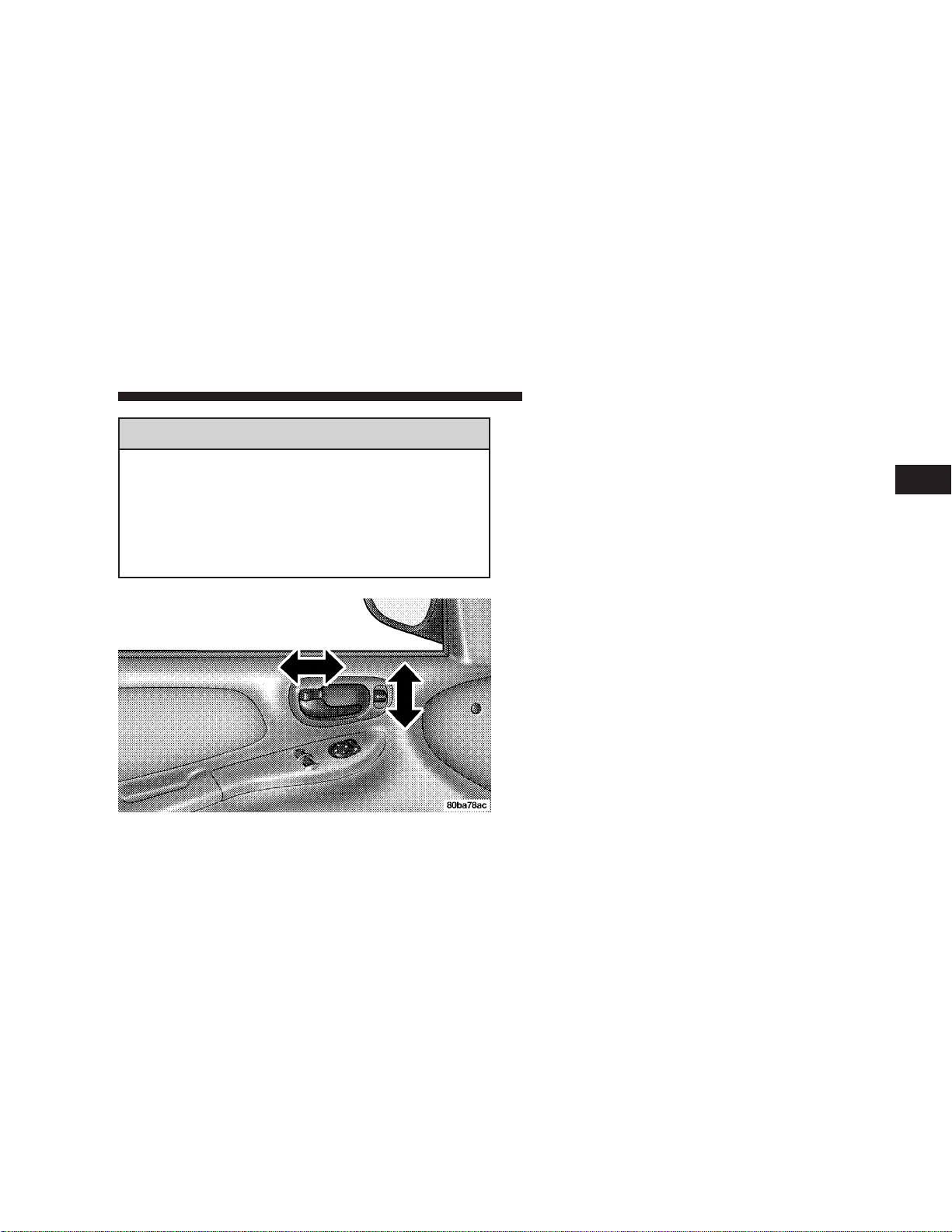
Electric Remote-Control Mirrors
Use the mirror select switch, located on the drivers door
trim panel, to adjust the view obtained in the outside
mirrors. Press the rocker knob to the L or R for Left or
Right mirror selection. Use the center off position to
guard against accidentally moving a mirror position.
Select a mirror and press one of the four arrows for the
direction you want the mirror to move.
SEATS
Front Seat Adjustment
The adjusting bar is at the front of the seats, near the
floor. Pull the bar up to move the seat to the desired
position.
Using body pressure, move forward and rearward on the
seat to be sure the seat adjusters have latched after the
adjustment bar is released.
Page 49

UNDERSTANDING THE FEATURES OF YOUR VEHICLE 49
WARNING!
•
Adjusting a seat while the vehicle is moving is
dangerous. The sudden movement of the seat
could cause you to lose control. The seat belt
might not be properly adjusted and you could be
injured. Adjust the seat only while the vehicle is
parked.
•
Do not ride with the seatback reclined so that the
shoulder belt is no longer resting against your
chest. In a collision you could slide under the seat
belt and be seriously or even fatally injured. Use
the recliner only when the vehicle is parked.
Reclining Bucket Seats
The recliner control is on the side of the seat. To recline,
lean forward slightly before lifting the lever, then lean
back to the desired position and release the lever. Lean
forward and lift the lever to return the seatback to its
normal position.
3
Page 50

50 UNDERSTANDING THE FEATURES OF YOUR VEHICLE
Folding Rear Seat
To provide additional storage area, the center of each rear
seatback can be folded forward. Pull on the loops shown
in the picture to fold down either or both seatbacks.
WARNING!
•
It is extremely dangerous to ride in a cargo area,
inside or outside of a vehicle. In a collision,
people riding in these areas are more likely to be
seriously injured or killed.
•
Do not allow people to ride in any area of your
vehicle that is not equipped with seats and seatbelts.
•
Be sure that everyone in your vehicle is in a seat
and using a seatbelt properly.
Page 51

UNDERSTANDING THE FEATURES OF YOUR VEHICLE 51
TO OPEN AND CLOSE THE HOOD
To open the hood, two latches must be released. First pull
the hood release lever located under the driver’s side of
the instrument panel.
Then lift the safety catch located under the front edge of
the hood, near the center and raise the hood.
3
Page 52

52 UNDERSTANDING THE FEATURES OF YOUR VEHICLE
Use the hood prop rod to secure the hood in the open
position as shown. To prevent possible damage, do not
slam the hood to close it. Use a firm downward push at
the center of the hood to ensure that both latches engage.
WARNING!
If the hood is not fully latched it could fly up when
the vehicle is moving and block your forward vision.
You could have a collision. Be sure all hood latches
are fully latched before driving.
LIGHTS
Front Map/Reading Lights
These lights, located under the rearview mirror, can be
turned on by means of switches located at the base of the
rearview mirror.
NOTE:
The map lights will remain on when the ignition
switch is in the Run or Accessory positions.
Page 53

UNDERSTANDING THE FEATURES OF YOUR VEHICLE 53
Interior Lights
The interior lights come on when a door is opened.
The interior lights will automatically turn off in about 8
minutes if a door is left open or the dimmer control is left
in the Dome light position. Turn the ignition switch ON
to restore the interior light operation.
Dimmer Control
With the park lights or headlights
on, rotating the dimmer control
for the interior lights on the MultiFunction Control Lever upward
will increase the brightness of the
instrument panel lights.
Dome Light Position
Rotate the dimmer control completely upward to the second detent to turn on the interior lights.
The interior lights will remain on
when the dimmer control is in this
position.
Daytime Brightness Feature
Certain instrument panel components can be illuminated
at full brightness during the daytime. These are the
Odometer and Radio. This can be helpful when driving
with your headlights on during the daytime such as in a
parade or a funeral procession. To activate this feature,
rotate the dimmer ring on the left stalk one detent lower
than the dome light.
Multi-Function Control Lever
The Multi-Function Control Lever controls the operation
of the headlights, parking lights, turn signals, headlight
beam selection, instrument panel light dimming, interior
3
Page 54

54 UNDERSTANDING THE FEATURES OF YOUR VEHICLE
lights, the passing lights, and fog lights. The lever is
located on the left side of the steering column.
Headlights, Parking Lights, Instrument Panel
Lights
Turn the end of the Multi-Function Control Lever to the
first detent for parking light operation. Turn to the
second detent for headlight operation.
To change the brightness of the instrument panel lights,
rotate the center portion of the Multi-Function Control
Lever up or down.
Daytime Running Lights (Canada Only)
The front fog lights will come on as Daytime Running
Lights whenever the ignition is on, the headlights are off,
and the parking brake is off. The headlight switch must
be used for normal night time driving.
Lights-on Reminder
If the headlights or parking lights are on after the ignition
is turned OFF, a chime will sound when the driver’s door
is opened. Leaving the headlights on for an extended
period of time will discharge the battery resulting in
reduced battery life and possible inability to start the
vehicle.
Fog Lights
The front fog light switch is on the Multi-Function
Control Lever. To activate the front fog lights, turn
on the headlights and pull out the end of the
control lever.
NOTE:
The fog lights will only operate with the headlights on low beam. Selecting high beam headlights or
park lights will turn off the fog lights.
Page 55

UNDERSTANDING THE FEATURES OF YOUR VEHICLE 55
Turn Signals
Move the Multi-Function Control Lever up or down to
detent and the arrows on each side of the instrument
cluster flash to show proper operation of the front and
rear turn signal lights. You can signal a lane change by
moving the lever partially up or down.
If either light remains on and does not flash, or there is a
very fast flash rate, check for a defective outside light
bulb. If an indicator fails to light when the lever is
moved, it would suggest that the fuse or indicator bulb is
defective.
Headlight Dimmer Switch
Pull the Multi-Function Control Lever towards you to
switch the headlights to HIGH beam. Pull the control
lever a second time to switch the headlights to LOW
beam.
Passing Light
You can signal another vehicle with your headlights by
lightly pulling the Multi-Function Control Lever toward
you. This will cause the headlights to turn on at high
beam and remain on until the lever is released.
WINDSHIELD WIPERS AND WASHERS
The wipers and washers are operated by a switch
in the control lever. Move the control lever up to
select the desired wiper speed.
3
Windshield Washers
To use the washer, pull the control lever toward you and
hold while spray is desired. If the lever is pulled while in
the delay range, the wiper will operate in low speed for
two wipe cycles after the lever is released, and then
resume the intermittent interval previously selected.
Page 56

56 UNDERSTANDING THE FEATURES OF YOUR VEHICLE
If the lever is pulled while in the OFF position, the wipers
will operate for two wipe cycles, then turn OFF.
CAUTION!
•
In cold weather, always turn off the wiper switch
and allow the wipers to return to the park position
before turning off the engine. If the wiper switch
is left on and the wipers freeze to the windshield,
damage to the wiper motor may occur when the
vehicle is restarted.
Mist Function
Push down on the wiper control lever to activate a single
wipe to clear the windshield of road mist or spray from
a passing vehicle. The wiper blade will continue to wipe
until you release the stalk.
Intermittent Wiper System
Use the intermittent wiper when weather conditions
make a single wiping cycle, with a variable pause between cycles, desirable. Move the lever to the first detent
(DEL) position, then select the delay interval by turning
the end of the stalk. Rotate the end upward to decrease
the delay time and downward to increase it. The delay
can be regulated from a maximum of approximately 18
seconds between cycles, to a second between cycles.
Lo Speed Wipers
Move the wiper stalk upward to the 2nd detent to obtain
a low speed wiper function.
Hi Speed Wipers
Move the wiper stalk upward to the 3rd position to
obtain the fastest wiper speed.
Page 57

UNDERSTANDING THE FEATURES OF YOUR VEHICLE 57
TILT STEERING COLUMN
To tilt the column, push down on the lever below the turn
signal control and move the wheel up or down, as
desired. Pull the lever back towards you to lock the
column firmly in place.
WARNING!
Tilting the steering column while the vehicle is
moving is dangerous. Without a stable steering column, you could lose control of the vehicle and have
an accident. Adjust the column only while the vehicle is stopped. Be sure it is locked before driving.
3
Page 58

58 UNDERSTANDING THE FEATURES OF YOUR VEHICLE
CONSOLE FEATURES
The Standard console with armrest has two front cup
holders and a front storage tray. There are two additional
cupholders; one is molded in the center of the console to
hold large cups, and the other is on the underside of the
console lid to serve passengers in the rear seat. The
underside console lid also has an integral tissue pack
holder. The covered storage area has CD and cassette
holders.
Ash Receiver and Cigar Lighter
When the Smoker’s Package is ordered from your authorized dealer, an ash receiver tray and a cigar lighter
element are furnished. The lighter element can be inserted in the auxiliary power outlet. The ash receiver fits
snugly in a cupholder position. To clean the ash receiver,
lift it from the cupholder.
Page 59

UNDERSTANDING YOUR INSTRUMENT PANEL
CONTENTS
m Instrument Panel Features
m Instrument Cluster—Turbo
m Instrument Cluster Descriptions
m Electronic Digital Clock
▫ Clock Setting Procedure..................68
m Radio General Information
▫ Radio Broadcast Signals ..................68
▫ Two Types Of Signals ...................68
▫ Electrical Disturbances ...................69
▫ AM Reception ........................69
▫ FM Reception .........................69
................61
................62
............63
..................68
................68
m Sales Code RBK—AM/ FM Stereo Radio With
CD Player And CD Changer Controls — If
Equipped
▫ Radio Operation .......................69
▫ CD Player Operation ....................71
▫ CD Changer Operation — If Equipped .......73
m Satellite Radio — If Equipped
▫ System Activation ......................74
▫ Electronic Serial Number/Sirius Identification
Number (ENS/SID) .....................74
▫ Selecting Satellite Mode In RBB And RBK
Radios ..............................75
.............................69
..............74
4
Page 60

60 UNDERSTANDING YOUR INSTRUMENT PANEL
▫ Selecting Satellite Mode In RBP, RBU, RAZ,
And RBQ Radios ......................75
▫ Selecting a Channel .....................75
▫ Storing And Selecting Pre-Set Channels .......76
▫ Using The PTY (Program Type) Button (If
Equipped) ...........................76
▫ PTY Button 9Scan9 ......................76
▫ PTY Button 9Seek9 ......................76
▫ Satellite Antenna .......................76
▫ Reception Quality ......................76
m Compact Disc Maintenance
m Radio Operation And Cellular Phones
m Climate Controls
.......................78
................77
........77
▫ Air Conditioning ......................78
▫ Operating Tips ........................81
m Electric Rear Window Defroster
m Turbo Boost Gauge
......................83
............83
Page 61

INSTRUMENT PANEL FEATURES
UNDERSTANDING YOUR INSTRUMENT PANEL 61
4
Page 62

62 UNDERSTANDING YOUR INSTRUMENT PANEL
INSTRUMENT CLUSTER—TURBO
Page 63

UNDERSTANDING YOUR INSTRUMENT PANEL 63
INSTRUMENT CLUSTER DESCRIPTIONS
1. Fog Light Indicator
This light shows when the fog lights are ON.
2. Brake System Warning Light
This light monitors various brake functions,
including brake fluid level and parking brake
application. If the brake light comes on, it may
indicate that the parking brake is applied, or there is a
low brake fluid level. It may also indicate an ABS
malfunction that could lead to reduced braking performance.
WARNING!
Driving a vehicle with the brake light on is dangerous. A significant decrease in braking performance
or vehicle stability during braking may occur. It will
take you longer to stop the vehicle or will make your
vehicle harder to control. You could have an accident. Have the vehicle checked immediately.
The operation of the Brake Warning light can be checked
by turning the ignition key from the OFF to the ON
position. The light should illuminate for three seconds, or
until the engine is started, whichever comes first. The
light should then go out unless the parking brake is
applied or a brake fault is detected. If the light does not
illuminate, have the light inspected and serviced as soon
as possible.
The light will also come on when the parking brake is
applied with the ignition in the ON position.
NOTE:
on. It does not show the degree of brake application.
If the parking brake is off and the light remains on, have
the brake system inspected as soon as possible.
3. Anti-Lock Warning Light (ABS)
light will come on when the ignition key is turned to
the ON position and may stay on for as long as four
seconds.
This light shows only that the parking brake is
This light monitors the Anti-Lock Brake System
(ABS) described elsewhere in this manual. This
4
Page 64

64 UNDERSTANDING YOUR INSTRUMENT PANEL
If the ABS light remains on or comes on during driving,
it indicates that theAnti-Lock portion of the brake system
is not functioning and that service is required, however,
the conventional brake system will continue to operate
normally provided that the BRAKE warning light is not
on.
If the ABS light is on, the brake system should be serviced
as soon as possible to restore the benefit of Anti-Lock
Brakes.
The warning light should be checked frequently to assure
that it is operating properly. Turn the ignition key to a
point midway between ON and START. The light should
come on. If the light does not come on, have the system
checked by an authorized dealer.
4. Speedometer
Indicates vehicle speed.
5. Turn Signal Indicators
The arrows will flash in unison with the exterior turn
signal, when using the turn signal lever.
6. High Beam Indicator
This light shows that the headlights are on high
beam. Pull the turn signal lever toward the
steering wheel to switch the headlights from high or
low beam.
7. Tachometer
The silver area of the scale shows the permissible engine
revolutions-per-minute (rpm x 1000) for each gear range.
Before reaching the red area, ease up on the accelerator to
prevent engine damage.
8. Oil Pressure Light
Shows low engine oil pressure. The light will
come on and remain on when the ignition key is
turned from OFF to the ON position, and the light will
turn off after the engine is started. If the bulb does not
come on during starting, have the system checked by
an authorized dealer.
If the light comes on and remains on while driving, stop
the vehicle and shut off the engine. DO NOT OPERATE
THE VEHICLE UNTIL THE CAUSE IS CORRECTED.
Page 65

UNDERSTANDING YOUR INSTRUMENT PANEL 65
The light does not show the quantity of oil in the engine.
This can be determined using the procedure shown in
Section 7.
9. Seat Belt Reminder Light
When the ignition key is first turned on, this
light will come on for about six seconds. A
chime will sound if you have not pulled the
shoulder belt out of the retractor. This is a reminder to
“buckle up”. If you do not buckle up, the light will
remain on.
10. Charging System Light
This light shows the status of the electrical
charging system. The light should come on
briefly when the ignition is first turned on and remain
on briefly as a bulb check. If the light stays on or
comes on while driving, it means that there is a
problem with the charging system. Obtain SERVICE
IMMEDIATELY.
11. Airbag Light
The light comes on and remains on for 6 to 8
seconds as a bulb check when the ignition
switch is first turned ON. If the light does not
come on during starting, stays on, or comes on while
driving, have the system checked by an authorized
dealer.
12. Theft Alarm Light
This light will flash rapidly for several seconds when the
alarm system is arming. The light will begin to flash
slowly indicating that the system is armed.
13. Fuel Door Reminder
This symbol is a reminder that the Fuel Filler Door is
located on the passenger’s side of the vehicle
14. Fuel Gauge
When the ignition key is in the ON position, the
pointer will show the level of fuel remaining in
the fuel tank.
15. Low Fuel Light
When the fuel level drops to about 1/8 tank, the
fuel symbol will light and a single chime will
sound. The light will remain on until fuel is
added. If the fuel level drops to about 1/2 gallon, the
fuel symbol will begin to flash and the chime will
sound several times.
4
Page 66

66 UNDERSTANDING YOUR INSTRUMENT PANEL
16. Malfunction Indicator Light
This light is part of an onboard diagnostic
system called OBD that monitors engine con-
trol systems. The light will illuminate briefly
when the key is in the ON/RUN position before
engine start. If the bulb does not come on when
turning the key from OFF to ON/RUN, have the
condition checked promptly.
Certain conditions such as a loose or missing gas cap,
poor fuel quality, etc., may illuminate the light after
engine start. The vehicle should be serviced if the light
stays on through several of your typical driving cycles. In
most situations, the vehicle will drive normally and will
not require towing.
If the Malfunction Indicator Light flashes when the
engine is running, serious conditions may exist that
could lead to immediate loss of power or severe catalytic
converter damage. The vehicle should be serviced as
soon as possible if this occurs.
17. Odometer/Trip Odometer Reset Knob
Press this knob to switch between the odometer and trip
odometer. While the trip odometer is being displayed,
press and hold this knob for a few seconds to reset the
trip odometer to zero miles/kilometers.
18. Odometer/Trip Odometer
Shows the total distance the vehicle has been driven.
U.S. Federal regulations require that upon transfer of
vehicle ownership, the seller certify to the purchaser the
correct mileage that the vehicle has been driven. Therefore, if the odometer reading changes during repair or
replacement, be sure to keep a record of the reading
before and after the service so the correct mileage can be
determined.
19. Door Ajar Indicator
This vacuum fluorescent indicator illuminates when a
door is not completely closed. If the door is open for more
than 8 minutes and the ignition key is in the OFF
position, the indicator will turn off.
Page 67

UNDERSTANDING YOUR INSTRUMENT PANEL 67
20. Trip Indicator
This light will illuminate when the Trip Odometer is in
use.
21. Temperature Gauge
The temperature gauge shows engine coolant
temperature.
Normal operating range should be
within one notch above or one notch
below the 200 degree mark. The
gauge pointer may show a higher
than normal temperature when driving in hot weather, up mountain
grades, or in heavy stop and go
traffic.
If the pointer rises to the H (red) mark, the instrument
cluster will sound a chime. Pull off to the side of the road
at a safe area. With the vehicle in Park (automatic
transmission), or with the vehicle in neutral and the
emergrncy brake applied (manual transmission), idle the
vehicle with the air conditioner turned off until the
pointer drops back into the normal range. If the pointer
remains on the H (red) mark, turn the engine off immediately and call for service.
There are steps that you can take to slow down an
impending overheat condition. If your air conditioning is
on, turn it off. The air conditioning system adds heat to
the engine cooling system and turning off the A/C
removes this heat. You can also turn the Temperature
control to maximum heat, the Mode control to Floor and
the Fan control to High. This allows the heater core to act
as a supplement to the radiator and aids in removing heat
from the engine cooling system.
4
Page 68

68 UNDERSTANDING YOUR INSTRUMENT PANEL
ELECTRONIC DIGITAL CLOCK
The clock and radio each use the display panel built into
the radio. A digital readout shows the time in hours and
minutes whenever the ignition switch is in the ON or
ACC position.
When the ignition switch is in the OFF position, or when
the radio frequency is being displayed, time keeping is
accurately maintained.
Clock Setting Procedure
1. Turn the ignition switch to the ON or ACC position.
Using the tip of a ballpoint pen or similar object, press
either the hour (H) or minute (M) buttons on the radio.
The display will show TIME.
2. Press the H button to set hours or the M button to set
minutes. The time setting will increase each time you
press a button.
RADIO GENERAL INFORMATION
Radio Broadcast Signals
Your new radio will provide excellent reception under
most operating conditions. Like any system, however, car
radios have performance limitations, due to mobile operation and natural phenomena, which might lead you to
believe your sound system is malfunctioning. To help
you understand and save you concern about these “apparent” malfunctions, you must understand a point or
two about the transmission and reception of radio signals.
Two Types of Signals
There are two basic types of radio signals... AM or
Amplitude Modulation, in which the transmitted sound
causes the amplitude, or height, of the radio waves to
vary... and FM or Frequency Modulation, in which the
frequency of the wave is varied to carry the sound.
Page 69

UNDERSTANDING YOUR INSTRUMENT PANEL 69
Electrical Disturbances
Radio waves may pick up electrical disturbances during
transmission. They mainly affect the wave amplitude,
and thus remain a part of the AM reception. They
interfere very little with the frequency variations that
carry the FM signal.
AM Reception
AM sound is based on wave amplitude, so AM reception
can be disrupted by such things as lightning, power lines
and neon signs.
FM Reception
Because FM transmission is based on frequency variations, interference that consists of amplitude variations
can be filtered out, leaving the reception relatively clear,
which is the major feature of FM radio.
SALES CODE RBK—AM/ FM STEREO RADIO
WITH CD PLAYER AND CD CHANGER
CONTROLS — IF EQUIPPED
Radio Operation
Power/Volume Control
Press the ON/VOL control to turn the radio on. Turn the
volume control clockwise to increase the volume.
NOTE:
the ignition switch. It must be in the ON or ACC position
to operate the radio.
Power to operate the radio is supplied through
4
Page 70

70 UNDERSTANDING YOUR INSTRUMENT PANEL
Seek
Press and release the SEEK button to search for the next
station in either the AM or FM mode. Press the top of the
button to seek up and the bottom to seek down. The
radio will remain tuned to the new station until you
make another selection. Holding the button in will bypass stations without stopping until you release it.
Tune
Press the TUNE control up or down to increase or
decrease the frequency. If you press and hold the button,
the radio will continue to tune until you release the
button. The frequency will be displayed and continuously updated while the button is pressed.
Balance
The Balance control adjusts the left-to-right speaker balance. Press the BAL button in and it will pop out. Adjust
the balance and push the button back in.
Fade
The Fade control provides for balance between the front
and rear speakers. Press the FADE button in and it will
pop out. Adjust the balance and push the button back in.
Bass and Treble Tone Control
The tone controls consist of 2 separate bands. The bass
band is on the left, and the treble band is on the right.
Each band is adjusted by a slider control with a detent at
the mid-position. Moving the control up or down increases or decreases amplification of that band. The mid
position provides a flat frequency response.
AM/FM Selection
Press the AM/FM button to change from AM to FM. The
operating mode will be displayed next to the station
frequency. The display will show ST when a stereo
station is received.
To Set The Radio Push-Button Memory
When you are receiving a station that you wish to
commit to push-button memory, press the SET button.
SET 1 will show in the display window. Select the “1–5”
button you wish to lock onto this station and press and
release that button. If a button is not selected within 5
seconds after pressing the SET button, the station will
continue to play but will not be locked into push-button
memory.
Page 71

UNDERSTANDING YOUR INSTRUMENT PANEL 71
You may add a second station to each push-button by
repeating the above procedure with this exception: Press
the SET button twice and SET 2 will show in the display
window. Each button can be set for SET 1 and SET 2 in
both AM and FM. This allows a total of 10 AM and 10 FM
stations to be locked into push-button memory. The
stations stored in SET 2 memory can be selected by
pressing the push-button twice. Every time a preset
button is used a corresponding button number will be
displayed.
Time
Press the TIME button to change the display between
radio frequency and time.
General Information
This radio complies with Part 15 of FCC rules and with
RSS-210 of Industry Canada. Operation is subject to the
following conditions:
1. This device may not cause harmful interference,
2. This device must accept any interference received,
including interference that may cause undesired operation.
NOTE:
proved by the party responsible for compliance could
void the user’s authority to operate the equipment.
CD Player Operation
NOTE:
position and the volume control ON before the CD player
will operate.
Inserting The Compact Disc
Changes or modifications not expressively ap-
The ignition switch must be in the ON or ACC
CAUTION!
This CD player will accept only 4.75 inch (12 cm)
discs only. The use of other sized discs may damage
the CD player mechanism.
You may either insert or eject a disc with the radio OFF.
If you insert a disc with the ignition ON and the radio
OFF, the display will show the time of day.
If the power is ON, the unit will switch from radio to CD
mode and begin to play when you insert the disc. The
4
Page 72

72 UNDERSTANDING YOUR INSTRUMENT PANEL
display will show the track number and index time in
minutes and seconds. Play will begin at the start of track 1.
Seek
Press the top of the SEEK button for the next selection on
the CD. Press the bottom of the button to return to the
beginning of the current selection, or return to the
beginning of the previous selection if the CD is within the
first second of the current selection.
EJT — Eject
Press the EJT button and the disc will unload and move
to the entrance for easy removal. The unit will switch to
the radio mode.
If you do not remove the disc within 15 seconds, it will be
reloaded. The unit will continue in radio mode.
The disc can be ejected with the radio and ignition OFF.
FF/TUNE/RW
Press FF (Fast Forward) and the CD player will begin to
fast forward until FF is released. The RW ( Reverse)
button works in a similar manner.
Random Play — RND
Press the RND button while the CD is playing to activate
Random Play. This feature plays the selections on the
compact disc in random order to provide an interesting
change of pace.
Press the SEEK button to move to the next randomly
selected track.
Press the RND button a second time to stop Random
Play.
Mode
Press the MODE button repeatedly to select between the
CD player, the optional remote CD changer and the
Satellite Radio (if equipped). When Satellite Radio (if
equipped) is selected “SA” will appear in your radio
display.
A CD or tape may remain in the player while in the
Satellite mode.
Time
Press the TIME button to change the display from
elapsed CD playing time to time of day.
Page 73

UNDERSTANDING YOUR INSTRUMENT PANEL 73
CD Changer Operation — If Equipped
MODE
Press the MODE button to select between the cassette
tape player,CD player, and the CD changer (if equipped).
Disc/Program Button 1
Press the DISC (button 1) button to play the next available disc.
Random Play — RND/Program Button 4
Press the RND (button 4) button while the CD is playing
to activate Random Play. This feature plays the selections
on the currently playing compact disc in random order to
provide an interesting change of pace.
Press the top of the SEEK button to move to the next
randomly selected track.
Press the RND (button 4) button a second time to stop
Random Play.
FF/RW — TUNE
Press FF/TUNE/RW to skip through the tracks in the
desired direction, until the button is released (it will not
stop at the beginning/end of any track until you release
the button).
Disc/Program Button 5
Press the DISC (button 5) button to play the previous
disc.
Seek
Press the top of the SEEK button for the next selection on
the CD. Press the bottom of the button to return to the
beginning of the current selection, or return to the
beginning of the previous selection if the CD is within the
first second of the current selection.
Time
Press the TIME button to switch between time of day and
CD track time.
Scan
Press the SCAN button to play 10 seconds of each track.
Press the SCAN button a second time to cancel the
feature.
4
Page 74

74 UNDERSTANDING YOUR INSTRUMENT PANEL
SATELLITE RADIO — IF EQUIPPED
Satellite radio uses direct satellite to receiver broadcasting technology to provide clear digital sound, coast to
coast. The subscription service provider is Sirius™ Satellite Radio. This service offers up to 100 channels of music,
sports, news, entertainment, and programming for children, directly from its satellites and broadcasting studios.
System Activation
To activate your Sirius Satellite Radio service, call the
toll-free number 888-539-7474, or visit the Sirius web site
at www.sirius.com. Please have the following information available when activating your system:
1. The Electronic Serial Number/Sirius Identification
Number (ESN/SID).
2. Credit card information.
3. Your Vehicle Identification Number.
Electronic Serial Number/Sirius Identification
Number (ENS/SID)
The Electronic Serial Number/Sirius Identification Number is needed to activate your Sirius Satellite Radio
system. To access the ESN/SID, refer to the following
steps:
ESN/SID Access With RBB and RBK Radios
With the ignition switch in the ACCESSORY position and
the radio OFF, press the Tape Eject or CD Eject (depending on the radio type) and Time buttons simultaneously
for 3 seconds. The first four digits of the twelve-digit
ESN/SID number will be displayed. Press the SEEK UP
button to display the next four digits. Continue to press
the SEEK UP button until all twelve ESN/SID digits have
been displayed. The SEEK DOWN will page down until
the first four digits are displayed. The radio will exit the
ESN/SID mode when any other button is pushed, the
ignition is turned OFF, or 5 minutes has passed since any
button was pushed.
Page 75

UNDERSTANDING YOUR INSTRUMENT PANEL 75
ESN/SID Access With RBP, RBU, RAZ, and RBQ
Radios
With the ignition switch in the ACCESSORY position and
the radio OFF, press the CD Eject and TIME buttons
simultaneously for 3 seconds. All twelve ESN/SID numbers will be displayed. The radio will exit the ESN/SID
mode when any other button is pushed, the ignition is
turned OFF, or 5 minutes has passed since any button
was pushed.
Selecting Satellite Mode in RBB and RBK Radios
Press the MODE button repeatedly until 9SA9 appears in
the display. A CD or tape may remain in the radio while
in the Satellite radio mode.
Selecting Satellite Mode in RBP, RBU, RAZ, and
RBQ Radios
Press the MODE button repeatedly until the word
9SIRIUS9 appears in the display. These radios will also
display the following:
•
After 3 seconds, the current channel name and channel
number will be displayed for 5 seconds.
•
The current program type and channel number will
then be displayed for 5 seconds.
•
The current channel number will then be displayed
until an action occurs.
A CD or tape may remain in the radio while in the
Satellite radio mode.
Selecting a Channel
Press and release the SEEK or TUNE buttons to search for
the next channel. Press the top of the button to search up
and the bottom of the button to search down. Holding the
TUNE button causes the radio to bypass channels until
the button is released.
Press and release the SCAN button (if equipped) to
automatically change channels every 7 seconds. The
radio will pause on each channel for 7 seconds before
moving on to the next channel. The word 9SCAN9 will
appear in the display between each channel change. Press
the SCAN button a second time to stop the search.
NOTE:
tent can be blocked. Contact Sirius Customer Care at
Channels that may contain objectionable con-
4
Page 76

76 UNDERSTANDING YOUR INSTRUMENT PANEL
888-539-7474 to discuss options for channel blocking or
unblocking. Please have your ESN/SID information
available.
Storing and Selecting Pre-Set Channels
In addition to the 10 AM and 10 FM pre-set stations, you
may also commit 10 satellite stations to push button
memory. These satellite channel pre-set stations will not
erase any AM or FM pre-set memory stations. Follow the
memory pre-set procedures that apply to your radio.
Using the PTY (Program Type) Button (if
equipped)
Follow the PTY button instructions that apply to your
radio.
PTY Button (SCAN(
When the desired program type is obtained, press the
9SCAN9 button within five seconds. The radio will play 7
seconds of the selected channel before moving to the next
channel of the selected program type. Press the 9SCAN9
button a second time to stop the search.
NOTE:
Pressing the 9SEEK9 or 9SCAN9 button while
performing a music type scan will change the channel by
one and stop the search. Pressing a pre-set memory
button during a music type scan, will call up the memory
channel and stop the search.
PTY Button (SEEK(
When the desired program is obtained, press the 9SEEK9
button within five seconds. The channel will change to
the next channel that matches the program type selected.
Satellite Antenna
To ensure optimum reception, do not place items on the
roof around the rooftop antenna location. Metal objects
placed within the line of sight of the antenna will cause
decreased performance. Larger luggage items should be
placed as far forward as possible. Do not place items
directly on or above the antenna.
Reception Quality
Satellite reception may be interrupted due to one of the
following reasons.
•
The vehicle is parked in an underground parking
structure or under a physical obstacle.
•
Dense tree coverage may interrupt reception in the
form of short audio mutes.
Page 77

UNDERSTANDING YOUR INSTRUMENT PANEL 77
•
Driving under wide bridges or along tall buildings can
cause intermittent reception.
•
Placing objects over or too close to the antenna can
cause signal blockage.
COMPACT DISC MAINTENANCE
To keep the compact discs in good condition, take the
following precautions:
1. Handle the disc by its edge; avoid touching the
surface.
2. If the disc is stained, clean the surface with a soft cloth,
wiping from center to edge.
3. Do not apply paper or tape to the disc; avoid scratching the disc.
4. Do not use solvents such as benzine, thinner, cleaners,
or antistatic sprays.
5. Store the disc in its case after playing.
6. Do not expose the disc to direct sunlight.
7. Do not store the disc where temperatures may become
too high.
NOTE:
lar disc, it may be damaged, oversized, or have theft
protection encoding. Try a known good disc before
considering disc player service.
RADIO OPERATION AND CELLULAR PHONES
Under certain conditions, the operation of a cellular
phone in your vehicle can cause erratic or noisy performance from your radio. This condition may be lessened
or eliminated by relocating the cellular phone antenna.
This condition is not harmful to the radio. If your radio
performance does not satisfactorily “clear” by the repositioning of the antenna, it is recommended that the radio
volume be turned down or off during cellular phone
operation.
If you experience difficulty in playing a particu-
4
Page 78

78 UNDERSTANDING YOUR INSTRUMENT PANEL
CLIMATE CONTROLS
Air Conditioning
The Air Conditioning System allows you to balance the
temperature, amount, and direction of air circulating
throughout the vehicle.
The air conditioning system of your vehicle contains
R-134a, a refrigerant that does not deplete the ozone layer
in the upper atmosphere.
The controls are as follows:
Fan and Air Conditioning Control
Use this control to regulate
the amount of air forced
through the system in any
mode you select. The fan
speeds to the left of the OFF
position are for Air Conditioning. Choosing one of these
speeds turns on the air conditioning compressor. The fan
speed increases as you move
the control counterclockwise from the OFF position.
NOTE:
The air conditioning compressor will not engage
until the engine has been running for about 10 seconds.
Fan speeds to the right of OFF are for heater or ventila-
tion operation. The fan speed increases as you move the
control clockwise from the OFF position.
Mode Control (Air Direction)
The mode control allows you
to choose from several patterns of air distribution. You
can select either a primary
mode, as identified by the
symbols, or a blend of two of
these modes. The center point
between modes gives an even
blend of both modes. The
closer the control is to a particular mode, the more air distribution you receive from
that mode.
Panel
Air is directed through the outlets in the instrument panel. These outlets can be adjusted to direct
air flow.
Page 79

UNDERSTANDING YOUR INSTRUMENT PANEL 79
Bi-Level
Air is directed through the panel and floor outlets.
NOTE:
upper and lower outlets for added comfort. The warmer
air goes to the floor outlets. This feature gives improved
comfort during sunny but cool conditions.
NOTE:
while the Circulation control is in the Recirculation
Mode, the system will automatically switch to the Outside Air mode and the knob will move to that position.
Floor
through the defrost outlet.
Mix
heat at the windshield. This setting is good for maintaining comfort while reducing moisture on the windshield.
There is a difference in temperature between the
If you choose either the Mix or Defrost modes
Air is directed through the floor outlets and side
window demist outlets with a small amount
Air is directed through the floor, defrost and side
window demist outlets. This setting works best
in cold or snowy conditions that require extra
Defrost
Air is directed through the windshield and side
window demist outlets. Use this mode with
maximum fan and temperature settings for best windshield and side window defrosting.
NOTE:
both Mix and Defrost or a blend of these modes even if
the fan switch is not in the A/C position. This dehumidifies the air to help dry the windshield. To improve fuel
economy, use these modes only when necessary.
Temperature Control
The air conditioning compressor operates in
Use this control to regulate
the temperature of the air inside the passenger compartment. The blue area of the
scale indicates cooler temperatures while the red area
indicates warmer temperatures.
4
Page 80

80 UNDERSTANDING YOUR INSTRUMENT PANEL
NOTE:
If your air conditioning performance seems
lower than expected, check the front of the A/C condenser located in front of the radiator, for an accumulation of dirt or insects. Clean with a gentle water spray
from behind the radiator and through the condenser.
Fabric front fascia protectors may reduce air flow to the
condenser, reducing air conditioning performance.
Circulation Control
Use this control to choose between outside air intake or
recirculation of the air inside
the vehicle. Only use the recirculate mode to temporarily
block out any outside odors,
smoke, or dust and to cool the
interior rapidly upon initial
start up in very hot or humid
weather.
This control only operates in the Outside Air and Recirculate modes; there is no in between position. Do not
place the control between these positions.
NOTE:
Continuous use of the recirculate mode may
make the inside air stuffy and window fogging may
occur. Extended use of this mode is not recommended.
In cold weather, the use of the Recirculate position will
cause windows to fog on the inside because of moisture
build up inside the vehicle. For maximum defogging,
select the Outside Air position.
If the mode control is in the range between Mix and
Defrost and you choose the Recirculate mode, the mode
control knob will automatically move to the Mix position.
NOTE:
If you choose either the Mix or Defrost modes
and the Circulation control is in the Recirculate Mode, the
system will automatically switch to the Outside Air
position.
Page 81

Operating Tips
UNDERSTANDING YOUR INSTRUMENT PANEL 81
4
Page 82

82 UNDERSTANDING YOUR INSTRUMENT PANEL
Window Fogging
Vehicle side windows tend to fog on the inside in mild
rainy or humid weather. To clear the windows, use the
A/C, PANEL and blower controls. Direct the panel
outlets toward the side windows. Do not use recirculate
without A/C for long periods as fogging may occur.
Interior fogging on the windshield can be quickly removed by using the defrost position.
If the fogging problem persists, clean the inside window
surfaces. The cause of undue fogging may be dirt collecting on the inside surface of the glass
NOTE:
In cold weather, the use of the recirculate
position will cause windows to fog on the inside because
of moisture build up inside the vehicle. For maximum
defogging, use the Outside Air position.
Summer Operation
Air conditioned vehicles must be protected with a highquality antifreeze coolant to provide proper corrosion
protection and to raise the boiling point of the coolant for
protection against overheating. A 50% concentration is
recommended.
Outside Air Intake
When operating the system during the winter months,
make sure the air intake, directly in front of the windshield, is free of ice, slush, snow or other obstructions
such as leaves. Leaves collected in the air-intake plenum
may reduce air flow and plug the plenum water drains.
The blower air will heat faster in cold weather if you use
only a low blower speed for the first few minutes of
vehicle operation.
Side Window Demisters
A side window demister outlet is at each end of the
instrument panel. These nonadjustable outlets direct air
toward the side windows when the system is in either the
FLOOR, MIX, or DEFROST mode. The air is directed at
the area of the windows through which you view the
outside mirrors.
Page 83

UNDERSTANDING YOUR INSTRUMENT PANEL 83
ELECTRIC REAR WINDOW DEFROSTER
A push-button at the center of the instrument
panel, below the radio, turns the defroster ON or
OFF. An amber light shows that the defroster is on.
NOTE:
minutes of operation. Each following activation of the
defroster will last for five minutes.
The defroster turns off automatically after 10
CAUTION!
To avoid damaging the electrical conductors, do not
use scrapers, sharp instruments, or abrasive window
cleaners on the interior surface of the rear window.
Labels can be peeled off after soaking with warm
water.
TURBO BOOST GAUGE
Your vehicle is equipped with a boost gauge that indicates the intake manifold pressure relative to barometric
pressure. The engine management system in your vehicle
intelligently regulates intake manifold pressure based on
environmental (ambient) and engine operating conditions. With the accelerator pedal fully depressed, it is
normal for the maximum intake manifold pressure
(boost) to vary from 11 to 15 psi.
If low octane fuel (below the recommended 91 octane
(R+M)/2)) is used, boost will be reduced significantly.
Normal boost levels will return once the recommended
fuel is used and the engine controller adapts to the fuel
octane level.
4
Page 84

Page 85

CONTENTS
STARTING AND OPERATING
m Starting Procedures
▫ Manual Transaxle ......................87
▫ Normal Starting .......................87
▫ Starting In Cold Weather
(Below 32°F Or 0°C) ....................87
▫ Extremely Cold Weather
(Below -20°F Or -29°C) ..................88
▫ If Engine Fails To Start ..................88
▫ After Starting .........................89
▫ Turbocharger “Cool Down” ...............89
m Manual Transaxle
▫ Recommended Shift Speeds ...............91
.....................87
.......................90
▫ Downshifting .........................92
m Parking Brake
m Brake System
▫ Anti-Lock Brake System (ABS) .............94
m Power Steering
m Tire Safety Information
▫ Tire Markings .........................96
▫ Tire Identification Number (TIN) ...........99
▫ Tire Loading And Tire Pressure ...........100
m Tires—General Information
▫ Tire Pressure .........................104
..........................92
..........................94
.........................95
...................96
...............104
5
Page 86

86 STARTING AND OPERATING
▫ Tire Inflation Pressures .................105
▫ Radial-Ply Tires ......................107
▫ Compact Spare Tire ....................107
▫ Tire Spinning ........................108
▫ Tread Wear Indicators ..................109
▫ Replacement Tires .....................109
▫ Alignment And Balance .................110
m Tire Chains
m Snow Tires
m Tire Rotation Recommendations
m Selecting Fuel
...........................111
...........................111
...........112
.........................113
▫ 2.4L Turbo ..........................113
▫ Spark Knock .........................113
▫ Reformulated Gasoline .................114
▫ Gasoline/Oxygenate Blends ..............114
▫ MMT In Gasoline .....................114
▫ Sulfur In Gasoline .....................115
▫ Materials Added To Fuel ................115
m Adding Fuel
..........................116
▫ Fuel Tank Filler Cap ...................116
m Vehicle Loading
.......................117
Page 87

STARTING AND OPERATING 87
STARTING PROCEDURES
Before starting your vehicle, adjust your seat, adjust both
inside and outside mirrors, and fasten your seat belts.
CAUTION!
Long periods of engine idling, especially at high
engine speeds can cause excessive exhaust temperatures which can damage your vehicle. Do not leave
your vehicle unattended with the engine running.
WARNING!
Do not leave children or animals inside parked
vehicles in hot weather. Interior heat build up may
cause serious injury or death.
Manual Transaxle
Place the gear selector in NEUTRAL, press the clutch
pedal to the floor, and fully apply the parking brake
before starting the engine.
NOTE:
is pressed to the floor.
Normal Starting
Normal Starting of either a cold or a warm engine does
not require pumping or depressing the accelerator pedal.
Simply turn the key to the START position and release
when the engine starts. If the engine has not started
within 5 seconds, slightly depress the accelerator pedal
while continuing to crank. If the engine fails to start
within 15 seconds, turn the key to the OFF position, wait
10 to 15 seconds, then repeat the normal starting procedure.
Starting in Cold Weather (Below 32°F or 0°C)
Slightly depress and hold the accelerator before starting
the engine. Turn the key to the START position. When the
engine starts, release the key, then the accelerator pedal.
The engine will not start unless the clutch pedal
5
Page 88

88 STARTING AND OPERATING
If the engine fails to start within 15 seconds, turn the key
OFF wait 10 to 15 seconds, then repeat the normal
starting procedure.
WARNING!
Do not attempt to push or tow your vehicle to get it
started. Unburned fuel could enter the catalytic
converter and once the engine has started, ignite and
damage the converter and vehicle. If the vehicle has
a discharged battery, booster cables may be used to
obtain a start from another vehicle. This type of start
can be dangerous if done improperly, so follow the
procedure carefully. See section 6 of this manual for
jump starting instructions.
Extremely Cold Weather (below -20°F or -29°C)
To insure reliable starting at these temperatures, use of an
externally powered electric engine block heater (available
from your dealer) is recommended.
If Engine Fails to Start
If the engine fails to start after you have followed the
“NORMAL STARTING” procedure, it may be flooded.
Push the accelerator pedal all the way to the floor and
hold it there. Crank the engine for no more than 15
seconds. This should clear any excess fuel in case the
engine is flooded. Leave the ignition key in the ON
position, release the accelerator pedal and repeat the
“NORMAL STARTING” procedure.
WARNING!
Never pour fuel or other flammable liquid into the
throttle body air inlet opening in an attempt to start
the vehicle. This could result in flash fire causing
serious personal injury.
Page 89

STARTING AND OPERATING 89
CAUTION!
To prevent damage to the starter, do not crank the
engine for more than 15 seconds at a time. Wait 10 to
15 seconds before trying again.
After Starting
The idle speed will automatically decrease as the engine
warms up.
TURBOCHARGER (COOL DOWN( CHART
Driving Conditions Idle Time (in minutes) Before Shut Down
Normal Driving Not required.
Aggressive Driving or Heavily Loaded 3
Turbocharger “Cool Down”
NOTE:
allows the turbine housing to cool to normal operating
temperature.
The following chart should be used as a guide in determinning the amount of engine idle time required to
sufficiently cool down the turbocharger before shut
down, depending upon the type of driving and the
amount of cargo.
Letting the engine idle after severe operation
5
Page 90

90 STARTING AND OPERATING
MANUAL TRANSAXLE
NOTE:
The parking brake should be engaged and the
gear selector placed in REVERSE before leaving the
vehicle, especially on an incline.
NOTE:
Clutch must be depressed for engine to start.
Fully depress the clutch pedal before you shift gears. As
you release the clutch pedal, lightly depress the accelerator pedal.
Use each gear in numerical order - do not skip a gear. Be
sure the transaxle is in FIRST gear, (not THIRD), when
starting from a standing position. Damage to the clutch
can result from starting in THIRD.
For most city driving you will find it easier to use only
the lower gears. For steady highway driving with light
accelerations, 5th gear is recommended.
Page 91

STARTING AND OPERATING 91
Never drive with your foot resting on the clutch pedal, or
try to hold the vehicle on a hill with the clutch pedal
partially engaged. This will cause abnormal wear on the
clutch.
Never shift into REVERSE until the vehicle has come to a
complete stop.
NOTE:
cant has warmed, you may have difficulty shifting. This
is normal and not harmful to the transaxle.
Recommended Shift Speeds
To use your manual transaxle for optimal fuel economy,
it should be upshifted as listed in tables 1 and 2.
TABLE 1-MANUAL TRANSAXLE RECOMMENDED
ENGINE NORMAL ACCELERATION SHIFT
TURBO
During cold weather, until the transaxle lubri-
SHIFT SPEEDS
IN MPH (KM/H)
SPEEDS
1to2 2to3 3to4 4to5
2.4L
14 23 29 45
(23) (37) (47) (72)
TABLE 2-MANUAL TRANSAXLE RECOMMENDED
SHIFT SPEEDS
IN MPH (KM/H)
ENGINE CRUISE SHIFT SPEEDS
1to2 2to3 3to4 4to5
2.4L
TURBO
For improved performance, your manual transaxle may
be upshifted up to the maximum speeds listed in table 3
(within legal speed limits).
TABLE 3-MANUAL TRANSAXLE RECOMMENDED
ENGINE MAXIMUM PERFORMANCESHIFT
SIZE 1 to 2 2 to 3 3 to 4 4 to 5
2.4L
12 18 25 32
(19) (29) (40) (51)
SHIFT SPEEDS
IN MPH (KM/H)
SPEEDS
30 50 80 110
(48) (80) (129) (177)
5
Page 92

92 STARTING AND OPERATING
If you exceed these speeds, you may notice the engine cut
in and out. This is caused by an electronic limiter in the
engine computer. The engine will run normally when
you reduce engine speed.
Downshifting
Proper downshifting may improve fuel economy and
prolong engine life.
CAUTION!
If you skip more than one gear while downshifting
or downshift at too high an engine speed, you could
damage the engine, transaxle, or clutch.
To maintain a safe speed and prolong brake life, shift
down to 2nd or 1st when descending a steep grade.
When turning a corner, or driving up a steep grade, shift
down early so that the engine will not be overburdened.
PARKING BRAKE
When the parking brake is applied with the
ignition on, the Brake Light in the instrument
cluster will come on.
NOTE:
This light only shows that the parking brake is
on. It does not show the degree of brake application.
Before leaving the vehicle, make sure that the parking
brake is set. To set the parking brake, pull up firmly on
the lever. Also place the gear selector in Reverse (manual
transaxle). To release the parking brake, apply the brake
pedal and pull up on the parking brake lever. Push the
release button and lower the lever fully.
Page 93

When parking on a hill,, turn the front wheels toward the
curb on a downhill grade and away from the curb on a
uphill grade.
You should always apply the parking brake before leaving the vehicle.
STARTING AND OPERATING 93
WARNING!
•
Leaving children in a vehicle unattended is dangerous for a number of reasons. A child or others
could be injured. Children should be warned not
to touch the parking brake or the gear selector.
Don’t leave the keys in the ignition. A child could
operate power windows, other controls, or move
the vehicle.
•
Be sure the parking brake is fully disengaged
before driving; failure to do so can lead to brake
failure and an accident.
5
Page 94

94 STARTING AND OPERATING
BRAKE SYSTEM
Your vehicle is equipped with power assisted brakes as
standard equipment. In the event power assist is lost for
any reason (for example, repeated brake applications
with the engine off), the brakes will still function. The
effort required to brake the vehicle will be much greater
than that required with the power system operating.
WARNING!
Riding the brakes can lead to brake failure and
possibly an accident. Driving with your foot resting
or riding on the brake pedal can result in abnormally
high brake temperatures, excessive lining wear, and
possible brake damage. You wouldn’t have your full
braking capacity in an emergency.
If either of the two hydraulic systems lose normal capability, the remaining system will still function with some
loss of overall braking effectiveness. This will be evident
by increased pedal travel during application and greater
pedal force required to slow or stop. In addition, if the
malfunction is caused by an internal leak, as the brake
fluid in the master cylinder drops, the brake warning
indicator will light.
Anti-Lock Brake System (ABS)
The ABS gives increased vehicle stability and brake
performance under most braking conditions. The system
automatically “pumps” the brakes during severe braking
conditions to prevent wheel lock up.
All vehicle wheels and tires must be the same size and
tires must be properly inflated to produce accurate
signals for the computer. However, the system will
compensate when the compact spare is in use.
During stops where ABS is activated, a vibration of the
brake pedal may be felt and associated system noises
may be heard.
NOTE:
Pumping of the brake pedal will diminish the
effectiveness of Anti-lock brakes and may lead to an
accident. Pumping makes the stopping distance longer.
Just press firmly on your brake pedal when you need to
slow down or stop.
Page 95

STARTING AND OPERATING 95
WARNING!
•
Anti-lock system (ABS) cannot prevent the natural laws of physics from acting on the vehicle, nor
can it increase braking or steering efficiency beyond that afforded by the condition of the vehicle
brakes and tires or the traction afforded.
•
The ABS cannot prevent accidents, including
those resulting from excessive speed in turns,
following another vehicle too closely, or hydroplaning. Only a safe, attentive, and skillful driver
can prevent accidents.
•
The capabilities of an ABS equipped vehicle must
never be exploited in a reckless or dangerous
manner which could jeopardize the user’s safety
or the safety of others.
POWER STEERING
The power assisted steering system of your SRT-4 provides mechanical steering capability in the event power
assist is lost.
If for some reason the hydraulic pressure is interrupted,
it will still be possible to steer your vehicle. Under these
conditions you will observe a substantial increase in
steering effort.
5
Page 96

96 STARTING AND OPERATING
TIRE SAFETY INFORMATION
Tire Markings
NOTE:
P(Passenger)-Metric tire sizing is based on U.S. design
•
standards. P-Metric tires have the letter “P” molded
into the sidewall preceding the size designation. Example: P215/65R15 95H.
•
European Metric tire sizing is based on European
design standards. Tires designed to this standard have
the tire size molded into the sidewall beginning with
the section width. The letter 9P9 is absent from this tire
size designation. Example: 215/65R15 96H
•
LT(Light Truck)-Metric tire sizing is based on U.S.
design standards. The size designation for LT-Metric
tires is the same as for P-Metric tires except for the
letters “LT” that are molded into the sidewall preceding the size designation. Example: LT235/85R16.
•
Temporary Spare tires are high pressure compact
spares designed for temporary emergency use only.
Tires designed to this standard have the letter “T”
molded into the sidewall preceding the size designation. Example: T145/80D18 103M.
•
High Flotation tire sizing is based on U.S. design
standards and begins with the tire diameter molded
into the sidewall. Example: 31x10.5 R15 LT.
Page 97

Tire Sizing Chart
Size Designation:
P = Passenger car tire size based on U.S. design standards
(....blank....( = Passenger car tire based on European design standards
LT = Light Truck tire based on U.S. design standards
T = Temporary Spare tire
31 = Overall Diameter in Inches (in)
215 = Section Width in Milimeters (mm)
65 = Aspect Ratio in Percent (%)
10.5 = Section Width in Inches (in)
R = Construction Code
15 = Rim Diameter in Inches (in)
STARTING AND OPERATING 97
EXAMPLE:
5
—Ratio of section height to section width of tire.
—9R9 means Radial Construction.
—9D9 means Diagonal or Bias Construction.
Page 98

98 STARTING AND OPERATING
EXAMPLE:
Service Description:
95 = Load Index
—A numerical code associated with the maximum load a tire can carry.
H = Speed Symbol
—A symbol indicating the range of speeds at which a tire can carry a load corresponding
to its load index under certain operating conditions.
—The maximum speed corresponding to the Speed Symbol should only be achieved under specified operating conditions. (ie. tire pressure, vehicle loading, road conditions and
posted speed limits).
Load Identification:
(....blank....( = Absence of any text on sidewall of the tire indicates a Standard Load (SL) Tire
Extra Load (XL) = Extra Load (or Reinforced) Tire
Light Load = Light Load Tire
C,D,E = Load range associated with the maximum load a tire can carry at a specified pressure
Maximum Load — Maximum Load indicates the maximum load this tire is designed to carry.
Maximum Pressure — Maximum Pressure indicates the maximum permissible cold tire inflation pressure for
this tire.
Page 99

STARTING AND OPERATING 99
Tire Identification Number (TIN)
The TIN may be found on one or both sides of the tire
however the date code may only be on one side. Tires
with white sidewalls will have the full TIN including
date code located on the white sidewall side of the tire.
EXAMPLE:
DOT MA L9 ABCD 0301
DOT = Department of Transportation
—This symbol certifies that the tire is in compliance with the U.S. Department of Transportation tire
safety standards, and is approved for highway use.
MA = Code representing the tire manufacturing location.(2 digits)
L9 = Code representing the tire size.(2 digits)
ABCD = Code used by tire manufacturer.(1 to 4 digits)
03 = Number representing the week in which the tire was manufactured.(2 digits)
—03 means the 3rd week.
01 = Number representing the year in which the tire was manufactured.(2 digits)
—01 means the year 2001.
—Prior to July 2000, tire manufacturers were only required to have 1 number to represent the year in
which the tire was manufactured. Example: 031 could represent the 3rd week of 1981 or 1991.
Look for the TIN on the outboard side of black sidewall
tires as mounted on the vehicle. If the TIN is not found on
the outboard side then you will find it on the inboard side
of the tire.
5
Page 100

100 STARTING AND OPERATING
Tire Loading and Tire Pressure
Tire Placard Location
NOTE:
Some vehicles have a “Tire and Loading Infor-
mation” placard located on the driver’s side “B” pillar.
Tire and Loading Information Placard
This placard tells you important information about
the,
1) number of people that can be carried in the vehicle
2) the total weight your vehicle can carry
3) the tire size designed for your vehicle
4) the cold tire inflation pressures for the front, rear
and spare tires.
 Loading...