

Page 1

DR/DH MESSAGE SYSTEMS 8M - 1
MESSAGE SYSTEMS
TABLE OF CONTENTS
page page
OVERHEAD CONSOLE - ELECTRICAL
DIAGNOSTICS ........................... 1
OVERHEAD CONSOLE - ELECTRICAL DIAGNOSTICS
TABLE OF CONTENTS
OVERHEAD CONSOLE - ELECTRICAL
DIAGNOSTICS
DIAGNOSIS AND TESTING
BUS MESSAGES MISSING ...............2
CMTC INTERNAL FAILURE ...............3
DEMAGNETIZE COMPASS AS PER
SERVICE MANUAL .....................4
FCM - AMBIENT TEMP CONFIGURATION
ERROR ..............................5
FCM - AMBIENT TEMP SENSOR INPUT
LOW ................................6
FCM - AMBIENT TEMP SENSOR INPUT
OPEN ...............................9
SET COMPASS VARIANCE AS PER
SERVICE INFORMATION ................12
OVERHEAD CONSOLE - SERVICE
INFORMATION.......................... 22
page page
*AVERAGE FUEL ECONOMY INACCURATE
OR WRONG..........................13
*DISTANCE TO EMPTY INACCURATE OR
WRONG.............................14
*ELAPSED IGNITION ON TIME
INACCURATE OR WRONG ..............15
*TRIP ODOMETER INACCURATE OR
WRONG.............................16
*CMTC OR EVIC INOPERATIVE ..........17
*COMPASS TEST FAILURE ..............19
*TEMPERATURE DISPLAY INACCURATE OR
INOPERATIVE ........................20
SCHEMATICS AND DIAGRAMS ............21
OVERHEAD CONSOLE - ELECTRICAL DIAGNOSTICS
DIAGNOSIS AND TESTING
Page 2

8M - 2 OVERHEAD CONSOLE - ELECTRICAL DIAGNOSTICS DR/DH
BUS MESSAGES MISSING
For a complete wiring diagram Refer to Section 8W.
Possible Causes
NO RESPONSE - PCI BUS - PCM
NO RESPONSE - PCI BUS - MIC
NO RESPONSE - PCI BUS - PCM
1.
Turn the ignition on.
With the DRBIIIT, select SYSTEM MONITORS, then J1850 Module Scan..
Does the DRBIIIT display PCM Active on the Bus?
Yes >>
No >>
NO RESPONSE - PCI BUS - MIC
2.
Turn the ignition on.
With the DRBIIIT, select Electro/Mechanical Instrument Cluster.
Is there a response from the Instrument Cluster?
Yes >>
No >>
Go To 2
Refer to COMMUNICATION category for the related symptom.
Perform BODY VERIFICATION TEST - VER 1. (Refer to BODY VERIFICATION TEST - VER 1.)
Replace and configure the Electronic Overhead Module in accordance with the Service Information.
Perform BODY VERIFICATION TEST - VER 1. (Refer to BODY VERIFICATION TEST - VER 1.)
Refer to COMMUNICATION category for the related symptom.
Perform BODY VERIFICATION TEST - VER 1. (Refer to BODY VERIFICATION TEST - VER 1.)
Page 3

DR/DH OVERHEAD CONSOLE - ELECTRICAL DIAGNOSTICS 8M - 3
CMTC INTERNAL FAILURE
For a complete wiring diagram Refer to Section 8W.
Possible Causes
ELECTRONIC OVERHEAD MODULE
Diagnostic Test
ELECTRONIC OVERHEAD MODULE
1.
Perform the EOM Self Test.
Turn the ignition off.
Press and hold the C/T button and the RESET button.
Turn the ignition on.
NOTE: The EOM Self Test can also be performed using the DRBIIIT.
Turn the ignition on.
With the DRBIIIT, select body, EOM, System Test, then Self Test.
Observe the DRBIIIT or the EOM display following the Self Test.
When the trouble code EOM INTERNAL FAILURE is displayed, View repair.
Repair
Replace and program the Electronic Overhead Module in accordance with the service information.
Perform BODY VERIFICATION TEST - VER 1. (Refer to BODY VERIFICATION TEST - VER 1.)
Page 4

8M - 4 OVERHEAD CONSOLE - ELECTRICAL DIAGNOSTICS DR/DH
DEMAGNETIZE COMPASS AS PER SERVICE MANUAL
For a complete wiring diagram Refer to Section 8W.
Possible Causes
DEMAGNETIZE COMPASS
Diagnostic Test
DEMAGNETIZE COMPASS
1.
NOTE: A blank compass display indicates that vehicle demagnetizing is required.
NOTE: After demagnetizing, the vehicle will enter Auto Fast-Cal when the ignition is turned on.
NOTE: Ensure that the correct compass variance is stored in the compass memory. See (Setting Compass
Variance( in the Service Information.
Refer to the Service Information for the Demagnetizing Procedure.
View repair for Verification Test.
Repair
When the Demagnetizing Procedure is complete perform the Verification Test.
Perform BODY VERIFICATION TEST - VER 1. (Refer to BODY VERIFICATION TEST - VER 1.)
Page 5

DR/DH OVERHEAD CONSOLE - ELECTRICAL DIAGNOSTICS 8M - 5
FCM - AMBIENT TEMP CONFIGURATION ERROR
For a complete wiring diagram Refer to Section 8W.
• When Monitored:
During power up.
• Set Condition:
The FCM detects that an Ambient Temperature Sensor is present on the input circuit and has gone through
auto-configuration and another module is transmitting a redundant ambient temp message.
Possible Causes
INCORRECT CONFIGURATION
Diagnostic Test
INCORRECT CONFIGURATION
1.
NOTE: This code will only set if the FCM detects that another module transmitting a redundant ambient
temp message.
NOTE: Diagnose and repair any Communication DTCs before proceeding with this test.
Ensure that the vehicle has only one Ambient Temperature Sensor, and that it is hardwired to the FCM.
With the DRBIIIT, erase DTCs.
Cycle the ignition to auto-configure the FCM.
With the DRBIIIT, read DTCs.
Did this DTC reset?
Yes >>
No >>
Ensure that the vehicle is not equipped with multiple Ambient Temperature Sensors. If vehicle is
equipped with NGC, disconnect the ambient temp sensor to the FCM and cycle the ignition.
Perform BODY VERIFICATION TEST - VER 1. (Refer to BODY VERIFICATION TEST - VER 1.)
Replace and program the Front Control Module in accordance with the Service Information.
Perform BODY VERIFICATION TEST - VER 1. (Refer to BODY VERIFICATION TEST - VER 1.)
Page 6
8M - 6 OVERHEAD CONSOLE - ELECTRICAL DIAGNOSTICS DR/DH
FCM - AMBIENT TEMP SENSOR INPUT LOW
Page 7
DR/DH OVERHEAD CONSOLE - ELECTRICAL DIAGNOSTICS 8M - 7
FCM - AMBIENT TEMP SENSOR INPUT LOW (CONTINUED)
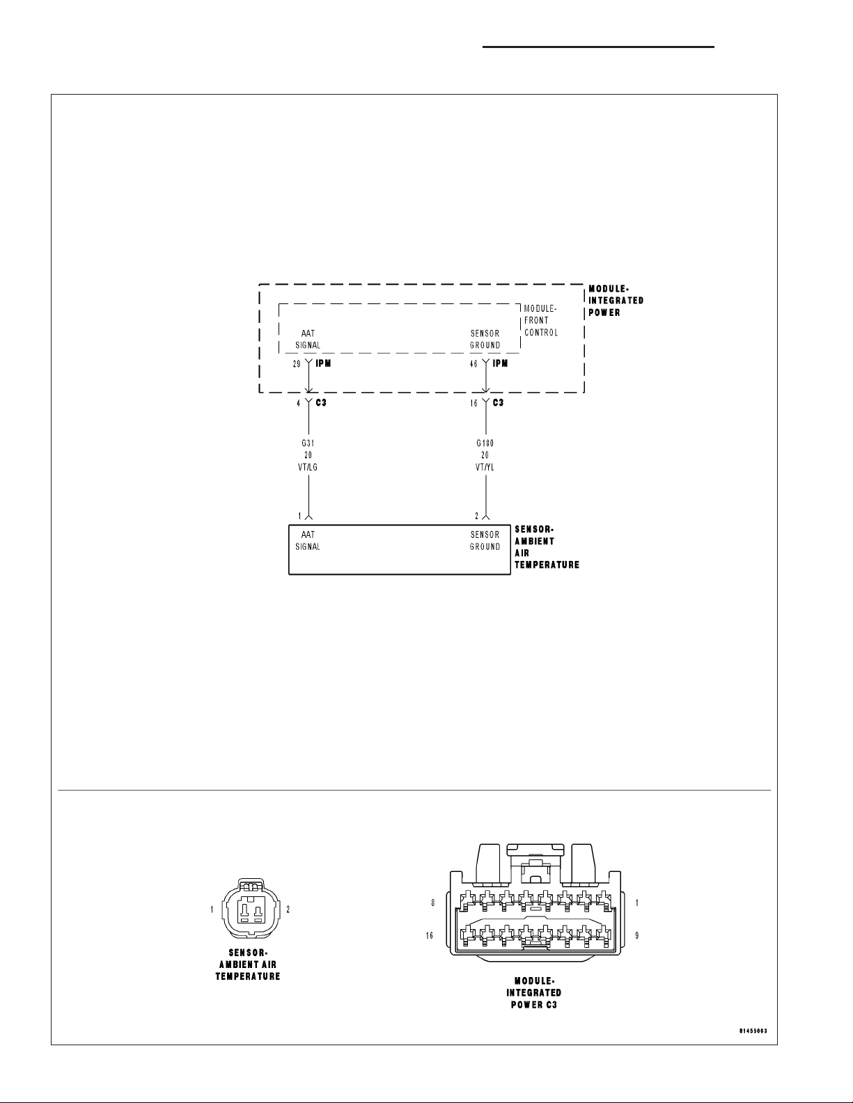
For the Electronic Overhead Module circuit diagram (Refer to 8 - ELECTRICAL/OVERHEAD CONSOLE - SCHEMATICS AND DIAGRAMS).
For a complete wiring diagram Refer to Section 8W.
• When Monitored:
Continuous with the ignition on.
• Set Condition:
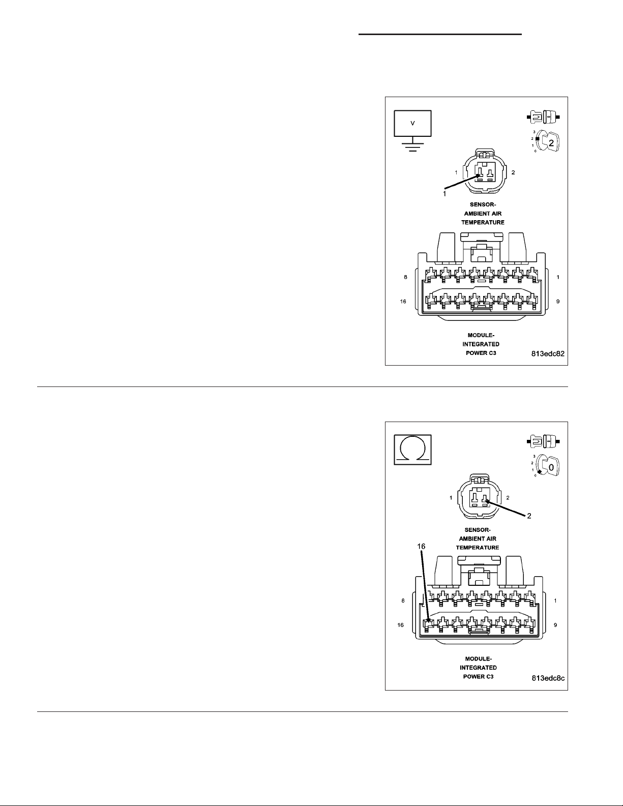
The FCM detects less than 0.5 volts on the Ambient Temperature Sensor Signal circuit.
Possible Causes
(G31) AMBIENT TEMPERATURE SENSOR SIGNAL CIRCUIT SHORTED TO GROUND
(G31) AMBIENT TEMPERATURE SENSOR SIGNAL CIRCUIT SHORTED TO THE (G180) AMBIENT
TEMPERATURE SENSOR GROUND CIRCUIT
AMBIENT TEMPERATURE SENSOR
Diagnostic Test
AMBIENT TEMPERATURE SENSOR
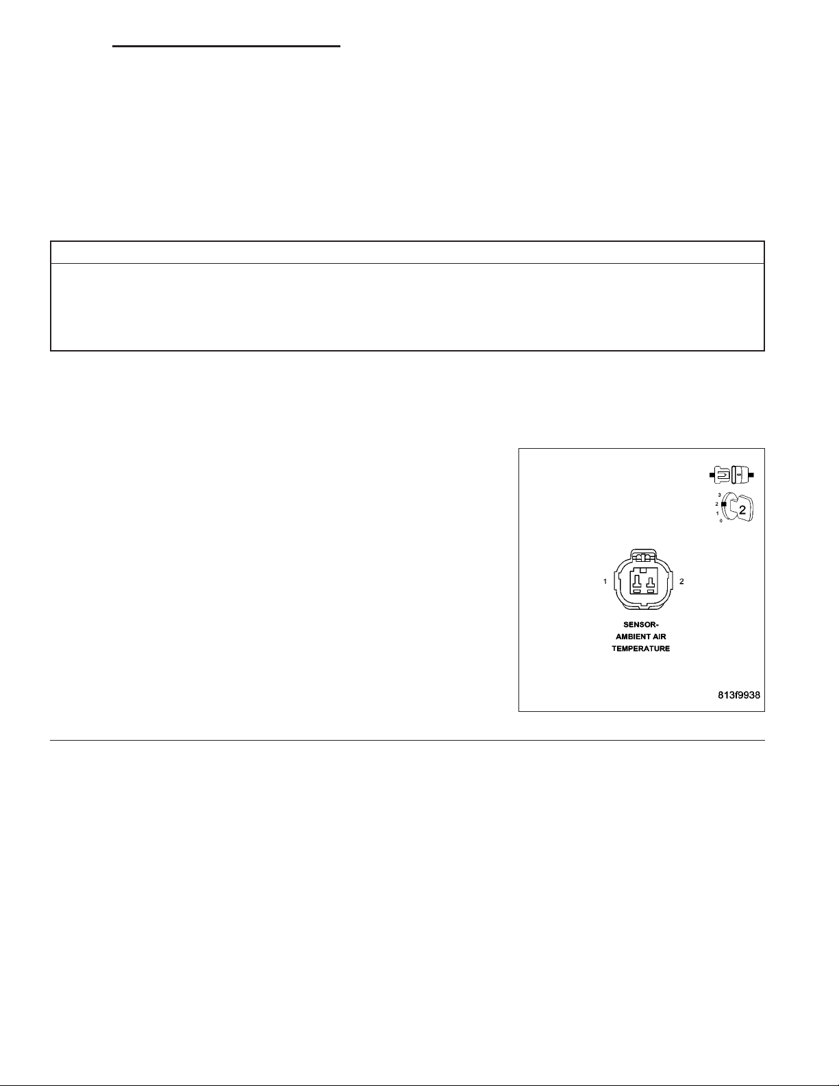
1.
Disconnect the Ambient Temperature Sensor harness connector.
Close all vehicle doors.
Turn the ignition on.
With the DRBIIIT in Sensors, read the Ambient Temperature Sensor
voltage.
Is the voltage above 4.8 volts?
Yes >>
No >>
Replace the Ambient Temperature Sensor.
Perform BODY VERIFICATION TEST - VER 1. (Refer to
BODY VERIFICATION TEST - VER 1.)
Go To 2
Page 8
8M - 8 OVERHEAD CONSOLE - ELECTRICAL DIAGNOSTICS DR/DH
FCM - AMBIENT TEMP SENSOR INPUT LOW (CONTINUED)
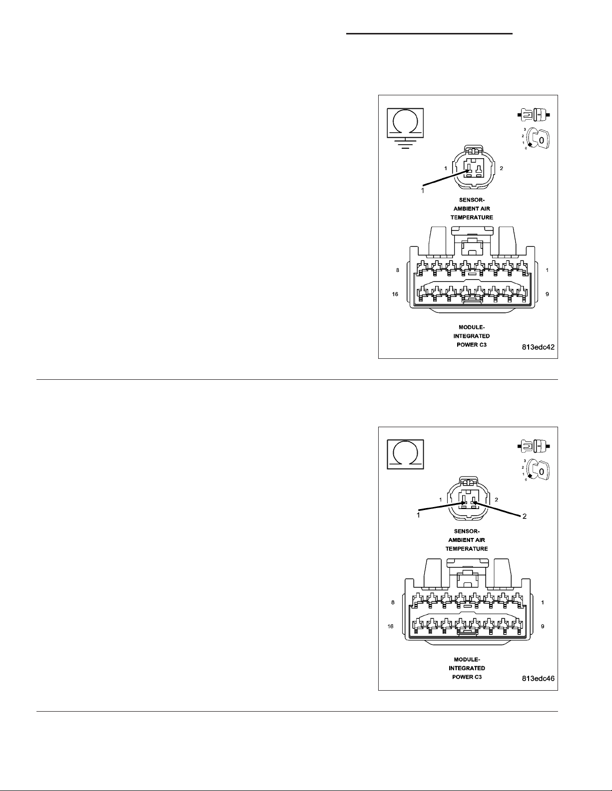
CHECK THE (G31) AMBIENT TEMPERATURE SENSOR SIGNAL CIRCUIT FOR A SHORT TO GROUND
2.
Turn the ignition off.
Disconnect the IPM C3 harness connector.
Measure the resistance between ground and the (G31) Ambient Tem-
perature Sensor Signal circuit.
Is the resistance below 5.0 ohms?
Yes >>
No >>
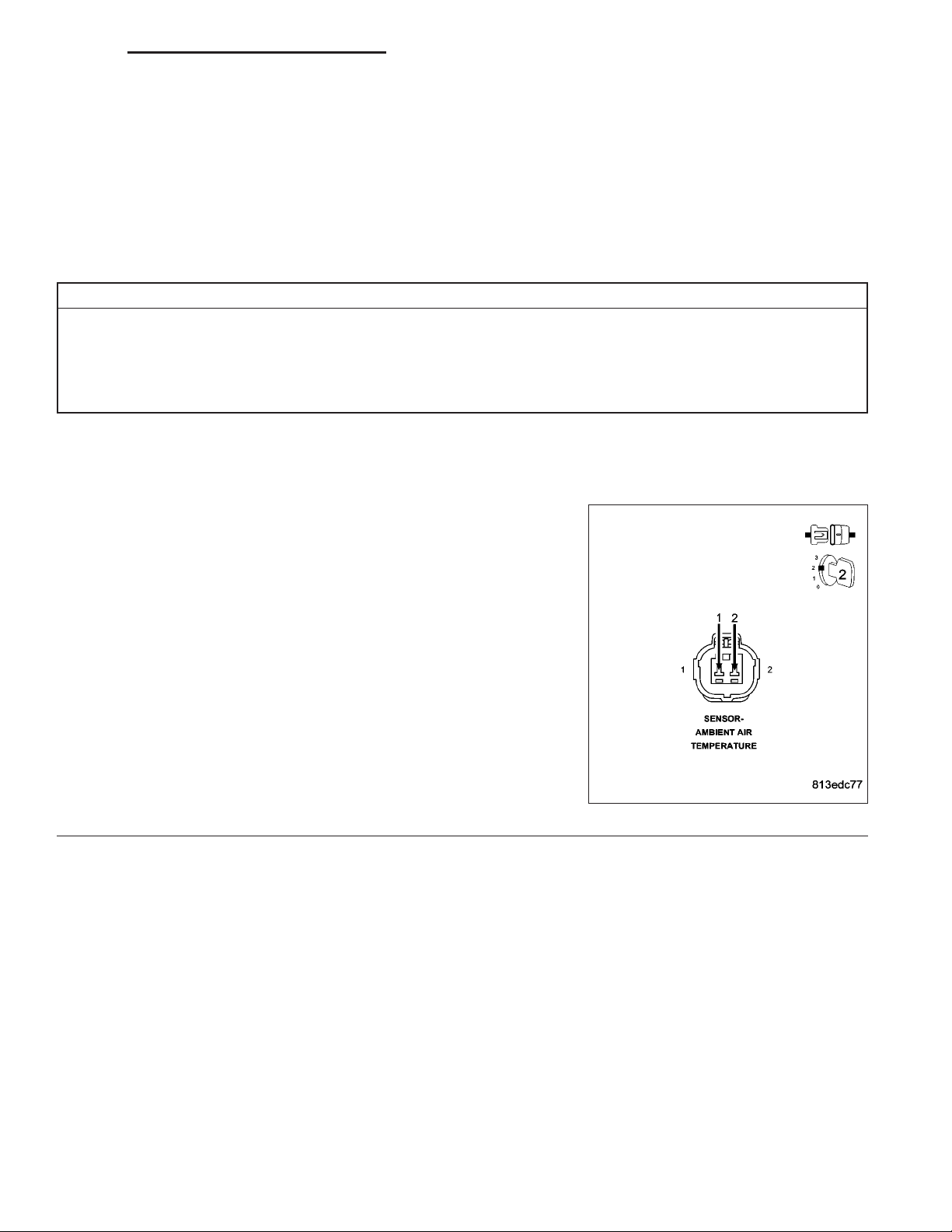
CHECK THE (G31) AMBIENT TEMPERATURE SENSOR SIGNAL CIRCUIT FOR A SHORT TO THE (G180)
3.
AMBIENT TEMPERATURE SENSOR GROUND CIRCUIT
Measure the resistance between the (G31) Ambient Temperature Sensor Signal circuit and the (G180) Ambient Temperature Sensor Ground
circuit.
Repair the (G31) Ambient Temperature Sensor Signal circuit for a short to ground.
Perform BODY VERIFICATION TEST - VER 1. (Refer to
BODY VERIFICATION TEST - VER 1.)
Go To 3
Is the resistance below 5.0 ohms?
Yes >>
No >>
Repair the (G31) Ambient Temperature Sensor Signal circuit for a short to the (G180) Ambient Temperature Sensor
Ground circuit..
Perform BODY VERIFICATION TEST - VER 1. (Refer to
BODY VERIFICATION TEST - VER 1.)
Replace the Front Control Module in accordance with the
Service Information.
Perform BODY VERIFICATION TEST - VER 1. (Refer to
BODY VERIFICATION TEST - VER 1.)
Page 9
DR/DH OVERHEAD CONSOLE - ELECTRICAL DIAGNOSTICS 8M - 9
FCM - AMBIENT TEMP SENSOR INPUT OPEN
For the Electronic Overhead Module circuit diagram (Refer to 8 - ELECTRICAL/OVERHEAD CONSOLE - SCHEMATICS AND DIAGRAMS).
For a complete wiring diagram Refer to Section 8W.
• When Monitored:
Continuous with the ignition on.
• Set Condition:
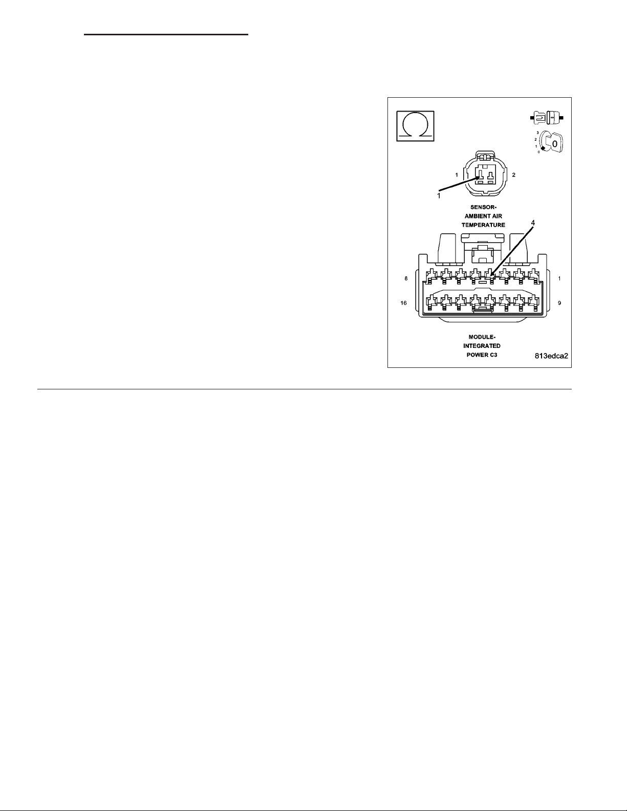
The FCM detects more than 5.0 volts on the Ambient Temperature Sensor Signal circuit.
Possible Causes
(G31) AMBIENT TEMPERATURE SENSOR SIGNAL CIRCUIT SHORT TO VOLTAGE
(G930) AMBIENT TEMPERATURE SENSOR GROUND CIRCUIT OPEN
(G31) AMBIENT TEMPERATURE SENSOR SIGNAL CIRCUIT OPEN
AMBIENT TEMPERATURE SENSOR
AMBIENT TEMPERATURE SENSOR
1.
Disconnect the Ambient Temperature Sensor harness connector.
Connect a jumper wire between the sensor signal and sensor ground
circuits.
Close all vehicle doors.
Turn the ignition on.
With the DRBIIIT in Sensors, read the Ambient Temperature Sensor
voltage.
Is the voltage below 0.5 volts?
Yes >>
No >>
Replace the Ambient Temperature Sensor.
Perform BODY VERIFICATION TEST - VER 1. (Refer to
BODY VERIFICATION TEST - VER 1.)
Go To 2
Page 10
8M - 10 OVERHEAD CONSOLE - ELECTRICAL DIAGNOSTICS DR/DH
FCM - AMBIENT TEMP SENSOR INPUT OPEN (CONTINUED)
CHECK THE (G31) AMBIENT TEMPERATURE SENSOR SIGNAL CIRCUIT FOR A SHORT TO VOLTAGE
2.
Turn the ignition off.
Disconnect the IPM C3 harness connector.
Turn the ignition on.
Measure the voltage between the (G31) Ambient Temperature Sensor
Signal circuit and ground.
Is there any voltage present?
Yes >>
No >>
CHECK THE (G180) AMBIENT TEMPERATURE SENSOR GROUND CIRCUIT FOR AN OPEN
3.
Turn the ignition off.
Measure the resistance of the (G180) Ambient Temperature Sensor
Ground circuit between the IPM C3 harness connector and the Ambient Temperature Sensor harness connector.
Is the resistance above 5.0 ohms?
Repair the (G31) Ambient Temperature Sensor Signal circuit for a short to voltage.
Perform BODY VERIFICATION TEST - VER 1. (Refer to
BODY VERIFICATION TEST - VER 1.)
Go To 3
Yes >>
No >>
Repair the (G180) Ambient Temperature Sensor Ground
circuit for an open.
Perform BODY VERIFICATION TEST - VER 1. (Refer to
BODY VERIFICATION TEST - VER 1.)
Go To 4
Page 11
DR/DH OVERHEAD CONSOLE - ELECTRICAL DIAGNOSTICS 8M - 11
FCM - AMBIENT TEMP SENSOR INPUT OPEN (CONTINUED)
CHECK THE (G31) AMBIENT TEMPERATURE SENSOR SIGNAL CIRCUIT FOR AN OPEN
4.
Measure the resistance of the (G31) Ambient Temperature Sensor Signal circuit between the IPM C3 harness connector and the Ambient
Temperature Sensor harness connector.
Is the resistance above 5.0 ohms?
Yes >>
No >>
Repair the (G31) Ambient Temperature Sensor Signal circuit for an open.
Perform BODY VERIFICATION TEST - VER 1. (Refer to
BODY VERIFICATION TEST - VER 1.)
Replace the Front Control Module in accordance with the
Service Information.
Perform BODY VERIFICATION TEST - VER 1. (Refer to
BODY VERIFICATION TEST - VER 1.)
Page 12

8M - 12 OVERHEAD CONSOLE - ELECTRICAL DIAGNOSTICS DR/DH
SET COMPASS VARIANCE AS PER SERVICE INFORMATION
For a complete wiring diagram Refer to Section 8W.
Possible Causes
SET COMPASS VARIANCE
SET COMPASS VARIANCE
1.
Refer to the Service Information for the Compass Variance procedure.
View repair for the Verification Test.
Repair
When the Compass Variance procedure is complete perform the Verification Test.
Perform BODY VERIFICATION TEST - VER 1. (Refer to BODY VERIFICATION TEST - VER 1.)
Page 13

DR/DH OVERHEAD CONSOLE - ELECTRICAL DIAGNOSTICS 8M - 13
*AVERAGE FUEL ECONOMY INACCURATE OR WRONG
For a complete wiring diagram Refer to Section 8W.
Possible Causes
ELECTRONIC OVERHEAD MODULE
ELECTRONIC OVERHEAD MODULE
1.
NOTE: Diagnose and repair any FCM, PCM, or Communication DTCs before proceeding with this test.
NOTE: Ensure that the EOM has been configured for the correct fuel tank size. Use the DRBIIIT to verify or
modify the fuel tank size configuration.
Perform the EOM Self Test.
The self test can be performed with the DRBIIIT or manually using the following procedure:
Turn the ignition off.
Press and hold the RESET and C/T buttons.
Turn the ignition on.
Continue to hold both buttons until the software version is displayed, then release the buttons.
Observe the EOM display when the self test is complete.
Did the EOM display (FAILED SELF TEST(?
Yes >>
No >>
Replace and configure the Electronic Overhead Module in accordance with the Service Information.
Perform BODY VERIFICATION TEST - VER 1. (Refer to BODY VERIFICATION TEST - VER 1.)
Test Complete.
Page 14

8M - 14 OVERHEAD CONSOLE - ELECTRICAL DIAGNOSTICS DR/DH
*DISTANCE TO EMPTY INACCURATE OR WRONG
For a complete wiring diagram Refer to Section 8W.
Possible Causes
ELECTRONIC OVERHEAD MODULE
ELECTRONIC OVERHEAD MODULE
1.
NOTE: Diagnose and repair any FCM, PCM, or Communication DTCs before proceeding with this test.
NOTE: Ensure that the EOM has been configured for the correct fuel tank size. Use the DRBIIIT to verify or
modify the fuel tank size configuration.
Perform the EOM Self Test.
The self test can be performed with the DRBIIIT or manually using the following procedure:
Turn the ignition off.
Press and hold the RESET and C/T buttons.
Turn the ignition on.
Continue to hold both buttons until the software version is displayed, then release the buttons.
Observe the EOM display when the self test is complete.
Did the EOM display (FAILED SELF TEST(?
Yes >>
No >>
Replace and configure the Electronic Overhead Module in accordance with the Service Information.
Perform BODY VERIFICATION TEST - VER 1. (Refer to BODY VERIFICATION TEST - VER 1.)
Test Complete.
Page 15

DR/DH OVERHEAD CONSOLE - ELECTRICAL DIAGNOSTICS 8M - 15
*ELAPSED IGNITION ON TIME INACCURATE OR WRONG
For a complete wiring diagram Refer to Section 8W.
Possible Causes
ELECTRONIC OVERHEAD MODULE
ELECTRONIC OVERHEAD MODULE
1.
NOTE: Diagnose and repair any FCM, PCM, or Communication DTCs before proceeding with this test.
NOTE: Ensure that the EOM has been configured for the correct fuel tank size. Use the DRBIIIT to verify or
modify the fuel tank size configuration.
Perform the EOM Self Test.
The self test can be performed with the DRBIIIT or manually using the following procedure:
Turn the ignition off.
Press and hold the RESET and C/T buttons.
Turn the ignition on.
Continue to hold both buttons until the software version is displayed, then release the buttons.
Observe the EOM display when the self test is complete.
Did the EOM display (FAILED SELF TEST(?
Yes >>
No >>
Replace and configure the Electronic Overhead module in accordance with the Service Information.
Perform BODY VERIFICATION TEST - VER 1. (Refer to BODY VERIFICATION TEST - VER 1.)
Test Complete.
Page 16

8M - 16 OVERHEAD CONSOLE - ELECTRICAL DIAGNOSTICS DR/DH
*TRIP ODOMETER INACCURATE OR WRONG
For a complete wiring diagram Refer to Section 8W.
Possible Causes
ELECTRONIC OVERHEAD MODULE
ELECTRONIC VEHICLE INFORMATION CENTER
1.
NOTE: Diagnose and repair any FCM, PCM, or Communication DTCs before proceeding with this test.
NOTE: Ensure that the EOM has been configured for the correct fuel tank size. Use the DRBIIIT to verify or
modify the fuel tank size configuration.
Perform the EOM Self Test.
The self test can be performed with the DRBIIIT or manually using the following procedure:
Turn the ignition off.
Press and hold the RESET and C/T buttons.
Turn the ignition on.
Continue to hold both buttons until the software version is displayed, then release the buttons.
Observe the EOM display when the self test is complete.
Did the EOM display (FAILED SELF TEST(?
Yes >>
No >>
Replace and configure the Electronic Overhead Module in accordance with the Service Information.
Perform BODY VERIFICATION TEST - VER 1. (Refer to BODY VERIFICATION TEST - VER 1.)
Test Complete.
Page 17

DR/DH OVERHEAD CONSOLE - ELECTRICAL DIAGNOSTICS 8M - 17
*CMTC OR EVIC INOPERATIVE
Page 18

8M - 18 OVERHEAD CONSOLE - ELECTRICAL DIAGNOSTICS DR/DH
*CMTC OR EVIC INOPERATIVE (CONTINUED)
For the Electronic Overhead Module circuit diagram (Refer to 8 - ELECTRICAL/OVERHEAD CONSOLE - SCHEMATICS AND DIAGRAMS).
For a complete wiring diagram Refer to Section 8W.
Possible Causes
(F21) FUSED IGNITION SWITCH OUTPUT (RUN/START) CIRCUIT OPEN
(Z13) ELECTRONIC OVERHEAD MODULE GROUND CIRCUIT OPEN
ELECTRONIC OVERHEAD MODULE
(F21) FUSED IGNITION RUN/START CIRCUIT OPEN
1.
NOTE: Diagnose and repair any MIC, FCM, PCM, or Communication DTCs before proceeding.
Turn the ignition off.
Disconnect the Electronic Overhead Module harness connector.
Turn the ignition on.
Measure the voltage between the (F21) Fused Ignition Switch Output
(Run/Start) circuit and ground.
Is the voltage below 10.5 volts?
Yes >>
No >>
(Z13) ELECTRONIC OVERHEAD MODULE GROUND CIRCUIT OPEN
2.
Trun the ignition off.
Measure the resistance between ground and the (Z13) Electronic
Overhead Module Ground circuit.
Is the resistance above 5.0 ohms?
Yes >>
No >>
Repair the (F21) Fused Ignition Switch Output (Run/Start)
circuit for an open.
Perform BODY VERIFICATION TEST - VER 1. (Refer to
BODY VERIFICATION TEST - VER 1.)
Go To 2
Repair the (Z13) Electronic Overhead Module Ground circuit for an open.
Perform BODY VERIFICATION TEST - VER 1. (Refer to
BODY VERIFICATION TEST - VER 1.)
Replace the Electronic Overhead Module in accordance
with the Service Information.
Perform BODY VERIFICATION TEST - VER 1. (Refer to
BODY VERIFICATION TEST - VER 1.)
Page 19

DR/DH OVERHEAD CONSOLE - ELECTRICAL DIAGNOSTICS 8M - 19
*COMPASS TEST FAILURE
For a complete wiring diagram Refer to Section 8W.
• When Monitored:
With the ignition on.
• Set Condition:
The Electronic Overhead Module (EOM) display reads “FAILED SELF TEST.”
Possible Causes
ELECTRONIC OVERHEAD MODULE
ELECTRONIC OVERHEAD MODULE
1.
Perform the EOM self test.
Turn the ignition off.
Depress and hold the RESET and C/T buttons while turning the ignition on.
NOTE: This test may also be performed using the DRBIIIT.
Does the EOM or DRBIIIT display (FAILED SELF TEST(?
Yes >>
No >>
Replace the EOM in accordance with the Service Information.
Perform BODY VERIFICATION TEST - VER 1. (Refer to BODY VERIFICATION TEST - VER 1.)
Test Complete.
Page 20

8M - 20 OVERHEAD CONSOLE - ELECTRICAL DIAGNOSTICS DR/DH
*TEMPERATURE DISPLAY INACCURATE OR INOPERATIVE
For the Electronic Overhead Module circuit diagram (Refer to 8 - ELECTRICAL/OVERHEAD CONSOLE - SCHEMATICS AND DIAGRAMS).
For a complete wiring diagram Refer to Section 8W.
Possible Causes
AMBIENT TEMPERATURE SENSOR
ELECTRONIC OVERHEAD MODULE
AMBIENT TEMPERATURE SENSOR
1.
NOTE: Diagnose and repair any FCM, EOM, PCM, or Communication DTCs before proceeding with this test.
NOTE: The Ambient Temperature Sensor is hardwired to the FCM
(Diesel), or to the PCM. Ambient temperature information is transmitted to the EOM via the PCI Bus.
Turn the ignition off.
Disconnect the Ambient Temperature Sensor harness connector.
Measure the resistance of the Ambient Temperature Sensor using the
following temperature/resistance values:
10°C (50°F) Sensor Resistance = 17.99 - 21.81 Kilohms
20°C (68°F) Sensor Resistance = 11.37 - 13.61 Kilohms
25°C (77°F) Sensor Resistance = 9.12 - 10.88 Kilohms
30°C (86°F) Sensor Resistance = 7.37 - 8.75 Kilohms
40°C (104°F) Sensor Resistance = 4.90 - 5.75 Kilohms
50°C (122°F) Sensor Resistance = 3.33 - 3.88 Kilohms
Is the Ambient Temperature Sensor resistance measurement within the min/max specifications?
Yes >>
No >>
ELECTRONIC OVERHEAD MODULE
2.
Perform the EOM self test.
Turn the ignition off.
Press and hold the C/T and Reset buttons.
Turn the ignition on.
NOTE: NOTE: The self test can also be performed using the DRBIIIT.
Observe the EOM display at the conclusion of the self test.
Does the EOM display (Passed Self Test(?
Yes >>
No >>
Go To 2
Replace the Ambient Temperature Sensor.
Perform BODY VERIFICATION TEST - VER 1. (Refer to BODY VERIFICATION TEST - VER 1.)
Test Complete.
Replace and configure the EOM in accordance with the Service Information.
Perform BODY VERIFICATION TEST - VER 1. (Refer to BODY VERIFICATION TEST - VER 1.)
Page 21

DR/DH OVERHEAD CONSOLE - ELECTRICAL DIAGNOSTICS 8M - 21
SCHEMATICS AND DIAGRAMS
EOM SYSTEM SCHEMATIC
Page 22

8M - 22 OVERHEAD CONSOLE - SERVICE INFORMATION DR/DH
OVERHEAD CONSOLE - SERVICE INFORMATION
TABLE OF CONTENTS
page page
OVERHEAD CONSOLE - SERVICE
INFORMATION
DESCRIPTION .........................22
DIAGNOSIS AND TESTING
OVERHEAD CONSOLE .................23
STANDARD PROCEDURE
READING/COURTESY LAMP
REPLACEMENT.......................25
MODULE LENS REPLACEMENT ..........25
MODULE LAMP REPLACEMENT ..........25
REMOVAL
OVERHEAD CONSOLE REMOVAL ........25
INSTALLATION .........................26
MODULE-COMPASS TEMPERATURE
DESCRIPTION .........................26
OPERATION ...........................27
DIAGNOSIS AND TESTING
COMPASS MINI-TRIP COMPUTER ........28
STANDARD PROCEDURE
COMPASS CALIBRATION ...............29
COMPASS DEMAGNETIZING ............30
COMPASS VARIATION ADJUSTMENT ......32
REMOVAL .............................33
INSTALLATION .........................33
UNIVERSAL TRANSMITTER
DESCRIPTION .........................34
OPERATION ...........................34
DIAGNOSIS AND TESTING
UNIVERSAL TRANSMITTER .............35
STANDARD PROCEDURE
PROGRAMMING TRANSMITTER CODES . . . 35
ERASING TRANSMITTER CODES .........36
REPROGRAMMING TRANSMITTER CODES . 36
SENSOR-AMBIENT AIR TEMPERATURE
DESCRIPTION .........................37
OPERATION ...........................37
DIAGNOSIS AND TESTING
AMBIENT TEMPERATURE SENSOR .......37
REMOVAL .............................38
INSTALLATION .........................38
OVERHEAD CONSOLE - SERVICE INFORMATION
DESCRIPTION
An overhead console is available on this vehicle and
includes the following components:
• Front map/reading lamps
• A blue-green vacuum-fluorescent display screen
- if equipped with trip computer
• Universal transmitter - if equipped
• Electronic Overhead Module (EOM)
The overhead console assembly is mounted by two
snap clips and screws securing it to a molded plastic
retainer bracket located above the headliner. The
EOM is accessed by removing the overhead console
from the bracket and pulling it away from the
headliner.
Page 23

DR/DH OVERHEAD CONSOLE - SERVICE INFORMATION 8M - 23
COMPASS DISPLAY
All the available overhead consoles on this model include Compass information. While in the compass/temperature
mode, the compass will display the direction in which the vehicle is pointed using the eight major compass headings
(Examples: north is N, northeast is NE). The self-calibrating compass unit requires no adjusting in normal use. The
only calibration that may prove necessary is to drive the vehicle at 5 to 8 kilometers-per-hour (3 to 5 miles-perhour), on level ground in a square shaped pattern. This will reorient the compass unit to its vehicle.
The compass unit also will compensate for magnetism the body of the vehicle may acquire during normal use.
However, avoid placing anything magnetic directly on the roof of the vehicle. Magnetic mounts for an antenna, a
repair order hat, or a funeral procession flag can exceed the compensating ability of the compass unit if placed on
the roof panel. Magnetic bit drivers used on the fasteners that hold the overhead console assembly to the roof
header can also affect compass operation. If the vehicle roof should become magnetized, the demagnetizing procedure may be required to restore proper compass operation. (Refer to 8 - ELECTRICAL/OVERHEAD CONSOLE STANDARD PROCEDURE - COMPASS DEMAGNETIZING) for the appropriate procedure.
TEMPERATURE DISPLAY
All the available overhead consoles on this model include Temperature information. The temperature displays the
outside ambient temperature in whole degrees. The temperature display can be toggled from Fahrenheit to Celsius
by selecting the desired U.S./Metric option from the customer programmable features. The displayed temperature is
not an instant reading of conditions, but an average temperature. It may take the temperature display several minutes to respond to a major temperature change, such as driving out of a heated garage into winter temperatures.
When the ignition switch is turned to the Off position, the last displayed temperature reading stays in the electronic
control modules, (CMTC, EVIC) memory. When the ignition switch is turned to the On position again, the electronic
module will display the memory temperature for one minute; then update the display to the current average temperature reading within five minutes.
The temperature function is supported by an ambient temperature sensor. This sensor is mounted outside the passenger compartment near the front and center of the vehicle, and is hard wired to the Front Control Module (FCM).
The FCM sends temperature status messages to the module over the Programmable Communications Interface
(PCI) data bus circuit. For more information on the ambient temperature sensor, (Refer to 8 - ELECTRICAL/OVERHEAD CONSOLE/AMBIENT TEMP SENSOR - DESCRIPTION).
DIAGNOSIS AND TESTING
OVERHEAD CONSOLE
If the problem with the overhead console is an inaccurate or scrambled display, refer to SELF- DIAGNOSTIC TEST
. If the problem with the overhead console is incorrect Vacuum Fluorescent Display (VFD) dimming levels, use a
scan tool and the proper Diagnostic Procedures Information to test for the correct dimming message inputs being
received from the Body Control Module (BCM) or Front Control Module (FCM) over the Programmable Communications Interface (PCI) data bus circuit. If the problem is a no-display condition, use the following procedure.
For complete circuit diagrams, refer to the appropriate wiring information. The wiring information includes wiring diagrams, proper wire and connector repair procedures, details of wire harness routing and retention, connector
pin-out information and location views for the various wire harness connectors, splices and grounds.
1. Remove the overhead console from the headliner (Refer to 8 - ELECTRICAL/OVERHEAD CONSOLE REMOVAL).
2. Check for battery voltage at the overhead console electrical connector. If OK, go to Step 3. If not OK, Check for
battery voltage at the appropriate B(+) fuse in the Integrated Power Module (IPM), repair the open fused B(+)
circuit as required.
3. Turn the ignition switch to the On position. Check the fused ignition switch output circuit(s) at the overhead console electrical connector. If OK, go to Step 4. If not OK, repair the open or shorted circuit as required.
4. Turn the ignition switch to the Off position. Disconnect and isolate the battery negative cable. Check for continuity
between the ground circuit cavity of the overhead console electrical connector and a good ground. There should
be continuity. If OK, refer to SELF- DIAGNOSTIC TEST for further diagnosis of the electronics module and the
PCI data bus circuit. If not OK, repair the open ground circuit as required.
Page 24

8M - 24 OVERHEAD CONSOLE - SERVICE INFORMATION DR/DH
SELF- DIAGNOSTIC TEST
A self-diagnostic test is used to determine that the EOM is operating properly electrically. Initiate the self-diagnostic
test as follows:
NOTE: The compass mini-trip computer self - test can also be performed using a scan tool. Refer to Auto
Self Test under the System Tests.
1. With the ignition switch in the Off position, simultaneously depress and hold the STEP and RESET buttons while
rotating the ignition switch to the Run/On position.
2. Continue to hold both buttons depressed until the EOM enters the display segment test. In this test, all of the
Vacuum Fluorescent Display (VFD) segments are lighted while the EOM performs the following checks:
• Non-Volatile Memory Status (NVM)
• RAM Status
• ROM Status
• ASIC Communication Test Status
• Compass Test Status
• DC Status
• PCI data bus Communications Test
NOTE: If module is equipped with the Universal Transmitter, the module also checks “Universal Transmitter
Communication Test Status”
3. Following completion of these tests, the compass mini-trip computer will display one of two messages: “FAIL” or
“PASS.” Press RESET or STEP to exit and enter normal mode. Respond to these test results as follows:
• If no test result message is displayed, but compass mini-trip computer operation is still improper, the use of a
scan tool and the proper Diagnostic Procedures Information are required for further diagnosis.
• If the “FAIL” message is displayed, the EOM is inoperative and must be replaced.
• If the “PASS” message is displayed, the EOM is OK, no faults are present.
• If any VFD segment does not light during the display segment test, the EOM is inoperative and must be
replaced.
4. If the first seven tests pass, the compass mini-trip computer shall verify that all the required PCI bus messages
are present on the PCI bus. If all required messages are present on the PCI bus, or if the ignition switch is
turned to the Off position, the EOM will automatically return to normal operation. The required PCI bus messages
are:
• Dimming message
• Fuel Used message
• Distance Pulses message
• Percentage Fuel Tank Full message
• Fuel Type message
• VIN (Vehicle Identification Number)
• Vehicle Speed message
• Last Engine Off Duration message
• Ambient Air Temperature message
NOTE: The Fuel Used message shall be ignored if the engine type is Diesel or Compressed Natural Gas.
NOTE: Pressing the STEP or RESET switches during any portion of the testing procedure will cause the
compass mini-trip computer to exit diagnostics and return to compass/temperature mode.
NOTE: If the compass functions, but accuracy is suspect, it may be necessary to perform a variation adjustment. This procedure allows the compass unit to accommodate variations in the earth’s magnetic field
strength, based on geographic location.
Page 25

DR/DH OVERHEAD CONSOLE - SERVICE INFORMATION 8M - 25
NOTE: If the compass reading has blanked out, and only “CAL” appears in the display, demagnetizing may
be necessary to remove excessive residual magnetic fields from the vehicle.
STANDARD PROCEDURE
READING/COURTESY LAMP REPLACEMENT
1. Disconnect and isolate the battery negative cable.
2. Remove the reading/courtesy lamp lens. Using a trim stick, gently pry the forward edge of the reading/courtesy
lamp lens outward.
3. Remove the reading/courtesy lamp socket from the overhead console. Rotate the reading/courtesy lamp socket
one quarter turn counter clockwise.
4. Remove the lamp and socket assembly.
5. Reverse the above procedure to install.
MODULE LENS REPLACEMENT
1. Remove the overhead console, (Refer to 8 - ELECTRICAL/OVERHEAD CONSOLE - REMOVAL).
2. Remove the electronic overhead module from the overhead console, (Refer to 8 - ELECTRICAL/OVERHEAD
CONSOLE/COMPASS/MINI-TRIP COMPUTER - REMOVAL).
3. Unsnap the lens from the module and replace lens as necessary.
MODULE LAMP REPLACEMENT
1. Remove the overhead console (Refer to 8 - ELECTRICAL/OVERHEAD CONSOLE - REMOVAL).
2. Using a flat blade screwdriver twist out socket/lamp
(3).
3. Replace lamp(s) as necessary.
REMOVAL
OVERHEAD CONSOLE REMOVAL
1. Disconnect and isolate the battery negative cable.
2. Remove the overhead console retaining screws, located in the sunglass storage bin.
3. Using your fingertips, grasp the sides of the overhead console and pull straight down evenly to disengage the
two snap clips at the front of the unit.
4. Lower the overhead console far enough to access the wire harness connectors.
5. Disconnect the Electronic Overhead Module and the reading/courtesy lamps electrical connectors.
Page 26

8M - 26 OVERHEAD CONSOLE - SERVICE INFORMATION DR/DH
6. Remove the overhead console from the vehicle.
INSTALLATION
1. Position the overhead console in the vehicle.
2. Connect the Electronic Overhead Module and the reading/courtesy lamps electrical connectors.
3. Grasp the sides of the overhead console and push straight up evenly to engage the two snap clips at the rear
of the unit.
4. Install the overhead console retaining screws, located in the sunglass storage bin. Torque the screws to 1.2 N·m
(10 in. lbs.).
5. Connect the battery negative cable.
MODULE-COMPASS TEMPERATURE
DESCRIPTION
The compass mini-trip computer is located in the overhead console (7) on models equipped with this option.
The compass mini-trip computer includes a VacuumFluorescent Display (VFD) (6), an Electronic Overhead
Module (EOM) and push button function switches (1,
2, 4 and 5).
The compass mini-trip computer module contains a
central processing unit and interfaces with other electronic modules in the vehicle on the Programmable
Communications Interface (PCI) data bus. The PCI
data bus allows the sharing of sensor information. This
helps to reduce wire harness complexity, reduce internal controller hardware, and reduce component sensor
current loads. At the same time, this system provides
increased reliability, enhanced diagnostics, and allows
the addition of many new feature capabilities.
The compass mini-trip computer provides several electronic functions and features. Some of the functions and features that the compass mini-trip computer supports and/or controls, include the following display options:
• Compass and temperature - provides the outside temperature and one of eight compass readings to indicate
the direction the vehicle is facing.
• Trip odometer (TRIP ODO) - shows the distance travelled since the last trip computer reset.
• Average fuel economy (AVG ECO) - shows the average fuel economy since the last trip computer reset.
• Distance to empty (DTE) - shows the estimated distance that can be travelled with the fuel remaining in the
fuel tank. This estimated distance is computed using the level of the fuel in the tank and a weighted average
of long term and recent Average Fuel Economy.
• Elapsed time (ET) - shows the accumulated ignition-on time since the last trip computer reset.
• Blank screen - the compass mini-trip VFD is turned off.
The ambient temperature sensor is hard wired to the Front Control Module (FCM). Data input for all other compass
mini-trip computer functions, including VFD dimming level, is received through PCI data bus messages. The compass mini-trip computer uses its internal programming and all of these inputs to calculate and display the requested
data. If the data displayed is incorrect, perform the self-diagnostic tests. (Refer to 8 - ELECTRICAL/OVERHEAD
CONSOLE - DIAGNOSIS AND TESTING) for the appropriate test procedure. If these tests prove inconclusive, the
use of a scan tool and the proper Diagnostic Procedures Information are recommended for further testing of the
EOM and the PCI data bus.
Page 27

DR/DH OVERHEAD CONSOLE - SERVICE INFORMATION 8M - 27
The EOM cannot be repaired, and is available for service only as a unit. This unit includes the push button
switches, the Universal Garage Door Transmitter and the plastic module and display lens. If any of these components is inoperative or damaged, the complete EOM must be replaced.
COMPASS
While in the compass/temperature mode, the compass will display the direction in which the vehicle is pointed using
the eight major compass headings (Examples: north is N, northeast is NE). The self-calibrating compass unit
requires no adjusting in normal use. The only calibration that may prove necessary is to drive the vehicle in one or
two complete circles, on level ground, in not less than 16 seconds. This will reorient the compass unit to its vehicle.
The compass unit also will compensate for magnetism the body of the vehicle may acquire during normal use.
However, avoid placing anything magnetic directly on the roof of the vehicle. Magnetic mounts for an antenna, a
repair order hat, or a funeral procession flag can exceed the compensating ability of the compass unit if placed on
the roof panel. Magnetic bit drivers used on the fasteners that hold the overhead console assembly to the roof
header can also affect compass operation. If the vehicle roof should become magnetized, (Refer to 8 - ELECTRICAL/OVERHEAD CONSOLE/COMPASS/MINI-TRIP COMPUTER - STANDARD PROCEDURE - COMPASS
DEMAGNETIZING) to restore proper compass operation.
TEMPERATURE
The temperature displays the outside ambient temperature in whole degrees. The temperature display can be
changed from Fahrenheit to Celsius using the U.S./Metric push button. The displayed temperature is not an instant
reading of conditions, but an average temperature. It may take the temperature display several minutes to respond
to a major temperature change, such as driving out of a heated garage into winter temperatures.
When the ignition switch is turned to the Off position, the last displayed temperature reading stays in the temperature unit memory. When the ignition switch is turned to the On position again, the temperature will display the
memory temperature if the engine OFF time is less than 90 minutes. If the engine OFF time is more than 90 minutes, the temperature will display the actual temperature sensed by the ambient temperature sensor. The temperature display update interval varies with the vehicle speed.
The temperature function is supported by an ambient temperature sensor. The sensor is mounted outside the passenger compartment near the front and center of the vehicle, and is hard wired to the FCM, which sends temperature over the PCI data bus circuit. The ambient temperature sensor is available as a separate service item, (Refer
to 8 - ELECTRICAL/OVERHEAD CONSOLE/AMBIENT TEMP SENSOR - DESCRIPTION).
NOTE: The compass mini-trip computer will display min and max temperatures of -40° C (-40° F) and 54°C
(130° F).
OPERATION
The compass mini-trip computer only operates with
the ignition switch in the On position. When the ignition switch is turned to the On position, all of the segments in the compass mini-trip computer VacuumFluorescent Display (VFD) will be turned off for one
second, then the display will return to the last function
being displayed before the ignition was turned to the
Off position. With the ignition switch in the On position,
momentarily depressing and releasing the Step push
button (4) will cause the compass-mini-trip computer
to change its mode of operation. Momentarily depressing and releasing the U.S./Metric push button (1) will
cause the unit to toggle between U.S. and Metric
measurements. Momentarily depressing and releasing
the C/T (compass/temperature) push button (5) will
cause the compass mini-trip computer to return to the
compass/temperature display mode from any other
mode.
This compass mini-trip computer features several
functions that can be reset. If the RESET push button
Page 28

8M - 28 OVERHEAD CONSOLE - SERVICE INFORMATION DR/DH
(2) is depressed for more than one second with the ignition switch in the On position, the trip computer information
that can be reset is reset. However, the reset will only occur if the function currently displayed is a function that can
be reset. The functions that can be reset are: TRIP ODO, AVG ECO, and ET. All three of these functions can be
reset at once by pressing the RESET button twice within 3 seconds while any one of the three functions is selected.
DIAGNOSIS AND TESTING
COMPASS MINI-TRIP COMPUTER
If the problem with the compass mini-trip computer is an inaccurate or scrambled display, refer to SELF- DIAGNOSTIC TEST . If the problem with the compass mini-trip computer is incorrect Vacuum Fluorescent Display (VFD)
dimming levels, use a scan tool and the proper Diagnostic Procedures Information to test for the correct dimming
message inputs being received from the Body Control Module (BCM) or Front Control Module (FCM) over the Programmable Communications Interface (PCI) data bus circuit. If the problem is a no-display condition, use the following procedure.
For complete circuit diagrams, refer to the appropriate wiring information. The wiring information includes wiring diagrams, proper wire and connector repair procedures, details of wire harness routing and retention, connector
pin-out information and location views for the various wire harness connectors, splices and grounds.
1. Remove the overhead console from the headliner (Refer to 8 - ELECTRICAL/OVERHEAD CONSOLE REMOVAL).
2. Check for battery voltage at the overhead console electrical connector. If OK, go to Step 3. If not OK, Check for
battery voltage at the appropriate B(+) fuse in the Integrated Power Module (IPM), repair the open fused B(+)
circuit as required.
3. Turn the ignition switch to the On position. Check the fused ignition switch output circuit(s) at the overhead console electrical connector. If OK, go to Step 4. If not OK, repair the open or shorted circuit as required.
4. Turn the ignition switch to the Off position. Disconnect and isolate the battery negative cable. Check for continuity
between the ground circuit cavity of the overhead console electrical connector and a good ground. There should
be continuity. If OK, refer to SELF- DIAGNOSTIC TEST for further diagnosis of the Electronic Overhead Module
and the PCI data bus circuit. If not OK, repair the open ground circuit as required.
SELF- DIAGNOSTIC TEST
A self-diagnostic test is used to determine that the EOM is operating properly electrically. Initiate the self-diagnostic
test as follows:
NOTE: The compass mini-trip computer self - test can also be performed using a scan tool. Refer to Auto
Self Test under the System Tests.
1. With the ignition switch in the Off position, simultaneously depress and hold the STEP and RESET buttons while
rotating the ignition switch to the Run/On position.
2. Continue to hold both buttons depressed until the EOM enters the display segment test. In this test, all of the
Vacuum Fluorescent Display (VFD) segments are lighted while the EOM performs the following checks:
• Non-Volatile Memory Status (NVM)
• RAM Status
• ROM Status
• ASIC Communication Test Status
• Compass Test Status
• DC Status
• PCI data bus Communications Test
NOTE: If module is equipped with the Universal Transmitter, the module also checks “Universal Transmitter
Communication Test Status”
3. Following completion of these tests, the compass mini-trip computer will display one of two messages: “FAIL” or
“PASS.” Press RESET or STEP to exit and enter normal mode. Respond to these test results as follows:
Page 29

DR/DH OVERHEAD CONSOLE - SERVICE INFORMATION 8M - 29
• If no test result message is displayed, but compass mini-trip computer operation is still improper, the use of a
scan tool and the proper Diagnostic Procedures Information are required for further diagnosis.
• If the “FAIL” message is displayed, the EOM is inoperative and must be replaced.
• If the “PASS” message is displayed, the EOM is OK, no faults are present.
• If any VFD segment does not light during the display segment test, the EOM is inoperative and must be
replaced.
4. If the first seven tests pass, the compass mini-trip computer shall verify that all the required PCI bus messages
are present on the PCI bus. If all required messages are present on the PCI bus, or if the ignition switch is
turned to the Off position, the EOM will automatically return to normal operation. The required PCI bus messages
are:
• Dimming message
• Fuel Used message
• Distance Pulses message
• Percentage Fuel Tank Full message
• Fuel Type message
• VIN (Vehicle Identification Number)
• Vehicle Speed message
• Last Engine Off Duration message
• Ambient Air Temperature message
NOTE: The Fuel Used message shall be ignored if the engine type is Diesel or Compressed Natural Gas.
NOTE: Pressing the STEP or RESET switches during any portion of the testing procedure will cause the
compass mini-trip computer to exit diagnostics and return to compass/temperature mode.
NOTE: If the compass functions, but accuracy is suspect, it may be necessary to perform a variation adjustment. This procedure allows the compass unit to accommodate variations in the earth’s magnetic field
strength, based on geographic location.
NOTE: If the compass reading has blanked out, and only “CAL” appears in the display, demagnetizing may
be necessary to remove excessive residual magnetic fields from the vehicle.
STANDARD PROCEDURE
COMPASS CALIBRATION
CAUTION: Do not place any external magnets, such as magnetic roof mount antennas, in the vicinity of the
compass. Do not use magnetic tools when servicing the overhead console.
The electronic compass unit features a self-calibrating design, which simplifies the calibration procedure. This feature automatically updates the compass calibration while the vehicle is being driven. This allows the compass unit
to compensate for small changes in the residual magnetism that the vehicle may acquire during normal use. If the
compass readings appear to be erratic or out of calibration, perform the following calibration procedure. Also, new
service replacement compass mini-trip computer modules must have their compass calibrated using this procedure.
Do not attempt to calibrate the compass near large metal objects such as other vehicles, large buildings, or bridges;
or, near overhead or underground power lines.
NOTE: Whenever the compass is calibrated manually, the variation number must also be reset. See Compass Variation Adjustment in the Service Procedures section of this group.
Calibrate the compass manually as follows:
1. Turn the ignition switch to the On position. If the compass/temperature data is not currently being displayed,
momentarily depress and release the C/T push button to step through the display options until you have reached
the compass/temperature display.
Page 30

8M - 30 OVERHEAD CONSOLE - SERVICE INFORMATION DR/DH
2. Depress and hold the RESET push button. Hold the push buttons down until “CAL” appears in the display. This
takes about ten seconds.
3. Drive the vehicle on a level surface, away from large metal objects and power lines, through one or twocomplete
circles in not less than 16 seconds. The “CAL” message will disappear from the display to indicate that the compass is now calibrated.
NOTE: A blank compass display indicates that vehicle degaussing (demagnetizing) is necessary.
NOTE: If the “CAL” message remains in the display, either there is excessive magnetism near the compass,
or the unit is faulty. Repeat the calibration procedure at least one more time.
NOTE: If the wrong direction is still indicated in the compass display, the area selected for calibration may
be too close to a strong magnetic field. Repeat the calibration procedure in another location.
COMPASS DEMAGNETIZING
A degaussing tool (Special Tool 6029) is used to
demagnetize, or degauss, the overhead console forward mounting screw and the roof panel above the
overhead console. Equivalent units must be rated as
continuous duty for 110/115 volts and 60 Hz. They
must also have a field strength of over 350 gauss at 7
millimeters (0.25 inch) beyond the tip of the probe.
To demagnetize the roof panel and the overhead console forward mounting screw, proceed as follows:
1. Be certain that the ignition switch is in the Off position, before you begin the demagnetizing procedure.
2. Connect the degaussing tool to an electrical outlet, while keeping the tool at least 61 centimeters (2 feet) away
from the compass unit.
3. Slowly approach the head of the overhead console forward mounting screw with the degaussing tool connected.
4. Contact the head of the screw with the plastic coated tip of the degaussing tool for about two seconds.
5. With the degaussing tool still energized, slowly back it away from the screw. When the tip of the tool is at least
61 centimeters (2 feet) from the screw head, disconnect the tool.
DEGAUSSING TOOL #6029
Page 31

DR/DH OVERHEAD CONSOLE - SERVICE INFORMATION 8M - 31
6. Place a piece of paper approximately 22 by 28
centimeters (8.5 by 11 inches), oriented on the
vehicle lengthwise from front to rear, on the center
line of the roof at the windshield header. The purpose of the paper is to protect the roof panel from
scratches, and to define the area to be demagnetized.
7. Connect the degaussing tool to an electrical outlet,
while keeping the tool at least 61 centimeters (2
feet) away from the compass unit.
8. Slowly approach the center line of the roof panel at
the windshield header, with the degaussing tool
connected.
9. Contact the roof panel with the plastic coated tip of
the degaussing tool. Be sure that the template is in
place to avoid scratching the roof panel. Using a
slow, back-and-forth sweeping motion, and allowing
13 millimeters (0.50 inch) between passes, move
the tool at least 11 centimeters (4 inches) to each
side of the roof center line, and 28 centimeters (11
inches) back from the windshield header.
10. With the degaussing tool still energized, slowly
back it away from the roof panel. When the tip of
the tool is at least 61 centimeters (2 feet) from the
roof panel, disconnect the tool.
11. Calibrate the compass, (Refer to 8 - ELECTRI-
CAL/OVERHEAD CONSOLE/COMPASS/MINITRIP COMPUTER - STANDARD PROCEDURE COMPASS CALIBRATION) and adjust the compass variance, (Refer to 8 - ELECTRICAL/OVERHEAD CONSOLE/COMPASS/MINI-TRIP COMPUTER - STANDARD PROCEDURE - COMPASS VARIATION
ADJUSTMENT).
Page 32

8M - 32 OVERHEAD CONSOLE - SERVICE INFORMATION DR/DH
COMPASS VARIATION ADJUSTMENT
Compass variance, also known as magnetic declination, is the difference in angle between magnetic north and true
geographic north. In some geographic locations, the difference between magnetic and geographic north is great
enough to cause the compass to give false readings. If this problem occurs, the compass variance must be set.
To set the compass variance:
1. Using the Variance Settings map, find your geographic location and note the zone number.
2. Turn the ignition switch to the On/Run position. If the compass/temperature data is not currently being displayed,
momentarily depress and release the C/T push button to step through the display options until you have reached
the compass/temperature display.
3. Press and hold the Reset push button down until “VAR” appears in the display. This takes about five seconds.
4. Momentarily depress and release the STEP push button to step through the zone numbers (1-15), until the zone
number for your geographic location appears in the display.
5. Momentarily depress and release the Reset push button to enter the displayed zone number into the compass
unit memory.
6. Confirm that the correct directions are now indicated by the compass.
Page 33

DR/DH OVERHEAD CONSOLE - SERVICE INFORMATION 8M - 33
REMOVAL
1. Disconnect and isolate the battery negative cable.
2. Remove the overhead console (1) from the headliner (Refer to 8 - ELECTRICAL/OVERHEAD CONSOLE - REMOVAL).
3. Remove the screws (4) that secure the Electronic
Overhead Module (EOM) (2) to the overhead console housing (1).
4. Disconnect the overhead console wire harness
connector from the EOM connector receptacle.
5. Remove the EOM (2) from the overhead console
housing (1).
INSTALLATION
NOTE: If a new Electronic overhead Module (EOM) has been installed, the compass will have to be calibrated and the variance set. (Refer to 8 - ELECTRICAL/OVERHEAD CONSOLE/COMPASS/MINI-TRIP COMPUTER - STANDARD PROCEDURE - COMPASS CALIBRATION) and (Refer to 8 - ELECTRICAL/OVERHEAD
CONSOLE/COMPASS/MINI-TRIP COMPUTER - STANDARD PROCEDURE - COMPASS VARIATION ADJUSTMENT) for the appropriate procedures.
1. Position the Electronic overhead Module (EOM) (2)
onto the overhead console housing (1).
2. Reconnect the overhead console wire harness connector to the EOM connector receptacle.
3. Install the screws (4) that secure the EOM (2) to
the overhead console housing (1). Tighten the
screws to 2.2 N·m (20 in. lbs.).
4. Install the overhead console (1) onto the headliner
(Refer to 8 - ELECTRICAL/OVERHEAD CONSOLE
- INSTALLATION).
5. Reconnect the battery negative cable.
Page 34

8M - 34 OVERHEAD CONSOLE - SERVICE INFORMATION DR/DH
UNIVERSAL TRANSMITTER
DESCRIPTION
The universal transmitter transceiver is integral to the
overhead console (7). The only visible component of
the universal transmitter are the three transmitter push
buttons (3). The buttons are marked with one, two or
three dots, respectively, for identification of each channel.
Each of the three universal transmitter push buttons
controls an independent radio transmitter channel.
Each of these three channels can be trained to transmit a different radio frequency signal for the remote
operation of garage door openers, motorized gate
openers, home or office lighting, security systems or
just about any other device that can be equipped with
a radio receiver in the 286 to 399 MegaHertz (MHz)
frequency range for remote operation. The universal
transmitter is capable of operating systems using
either rolling code or non-rolling code technology.
The universal transmitter cannot be repaired, and is
available for service only as part of the Electronic
Overhead Module (EOM). This unit includes the push button switches for both the transmitter and compass mini trip
computer, The Vacuum-Fluorescent Display (VFD) and the plastic module case. (Refer to 8 - ELECTRICAL/OVERHEAD CONSOLE/COMPASS/MINI-TRIP COMPUTER - REMOVAL) for EOM replacement.
OPERATION
The universal transmitter operates on a non-switched source of battery current so the unit will remain functional,
regardless of the ignition switch position. It can learn and store three separate transmitter radio frequency codes to
operate garage door openers, security gates and security lighting. The overhead console display provides visual
feedback to the driver, showing which transmitter button is pressed. The system will not send operating signals if the
vehicle theft security alarm is armed. This prevents a perpetrator from breaking into a vehicle parked outside a
home and using the transmitter system to enter the home.
Page 35

DR/DH OVERHEAD CONSOLE - SERVICE INFORMATION 8M - 35
DIAGNOSIS AND TESTING
UNIVERSAL TRANSMITTER
If both the Transmitter and the compass mini trip computer display are inoperative, (Refer to 8 - ELECTRICAL/OVERHEAD CONSOLE/COMPASS/MINI-TRIP
COMPUTER - DIAGNOSIS AND TESTING) for further
diagnosis. If the Universal Transmitter is inoperative,
but the compass mini trip computer display is operating normally, (Refer to 8 - ELECTRICAL/OVERHEAD
CONSOLE/UNIVERSAL TRANSMITTER - STANDARD PROCEDURE) for instructions on training the
Transmitter. Retrain the Transmitter with a known
good transmitter as instructed and test the Transmitter
operation again. If the unit is still inoperative, test the
universal transmitter with the Radio Frequency Detector special tool as described below:
1. Turn the Radio Frequency (RF) Detector ON. A
“chirp” will sound and the green power LED will
light. If the green LED does not light, replace the
battery.
2. Hold the RF detector within one inch of the
TRAINED universal transmitter and press any of
the transmitters buttons.
3. The red signal detection LEDs will light and the tool
will beep if a radio signal is detected. Repeat this
test for each button. If any button is inoperative,
replace the universal transmitter assembly, (Refer to 8 - ELECTRICAL/OVERHEAD CONSOLE/COMPASS/MINITRIP COMPUTER - REMOVAL).
For complete circuit diagrams, refer to the appropriate wiring information. The wiring information includes wiring diagrams, proper wire and connector repair procedures, details of wire harness routing and retention, connector
pin-out information and location views for the various wire harness connectors, splices and grounds.
RADIO FREQUENCY DETECTOR #9001
STANDARD PROCEDURE
PROGRAMMING TRANSMITTER CODES
CAUTION: Vehicle exhaust contains carbon monoxide, a dangerous gas. Do not run the vehicle’s exhaust
while training the transceiver. Exhaust gas can cause serious injury or death.
CAUTION: Your motorized door or gate will open and close while you are training the Universal Transceiver.
Do not train the transceiver if people or pets are in the path of the door or gate. A moving door or gate can
cause serious injury or death to people and pets or damage to objects.
1. Press and hold the two outer HomeLink buttons, and release only when the EVIC display shows “Channels
Cleared” (after 20 seconds). Do not hold the buttons for longer than 30 seconds and do not repeat step one to
program a second and/or third hand-held transmitter to the remaining two HomeLink buttons.
2. Position the end of your hand-held transmitter 1-3 inches (3-8 cm) away from the HomeLink buttons.
3. Simultaneously press and hold both the HomeLink button that you want to train and the hand-held transmitter
buttons. Do not release the buttons until step 4 has been completed.
4. The EVIC display will show “Channel X Training” (where X is Channel 1, 2, or 3). Release both buttons after the
EVIC display shows “Channel X Trained”.
NOTE: If the EVIC display shows “Did Not Train” repeat steps 2–4.
Page 36

8M - 36 OVERHEAD CONSOLE - SERVICE INFORMATION DR/DH
5. Press and hold the just trained HomeLink button and observe the EVIC display. If the EVIC display shows
“Channel X Transmit” (where X is Channel 1, 2, or 3), programming is complete and your device should activate
when the HomeLink button is pressed and released.
NOTE: To program the remaining two HomeLink buttons, begin with (Programming( step two. Do not repeat
step one.
NOTE: If your hand-held transmitter appears to program the universal transceiver, but your garage door
does not operate using the transmitter and your garage door opener was manufactured after 1995, your
garage door opener may have a multiple security code system (rolling code system). Please proceed to
steps 6–8 to complete the programming of a rolling code equipped device (most common garage door
openers require this step.
6. At the garage door opener receiver (motor-head unit) in the garage, locate the 9learn9 or 9smart9 button. This can
usually be found where the hanging antenna wire is attached to the motor-head unit.
7. Firmly press and release the 9learn9 or 9smart9 button. (The name and color of the button may vary by manufacturer.)
NOTE: There are 30 seconds in which to initiate step eight.
8. Return to the vehicle and firmly press, hold for two seconds and release the programmed HomeLink button.
Repeat the (press/hold/release( sequence a second time, and, depending on the brand of the garage door
opener (or other rolling code equipped device), repeat this sequence a third time to complete the programming.
9. HomeLink should now activate your rolling code equipped device.
10. To program the remaining two HomeLink buttons, begin with 9Programming9 step two. Do not repeat step
one.
ERASING TRANSMITTER CODES
NOTE: Individual channels cannot be erased. Erasing the transmitter codes will erase ALL programmed
codes.
To erase programming from the three buttons (individual buttons cannot be erased but can be 9reprogrammed9),
follow the step noted:
• Press and hold the two outer HomeLink buttons until the indicator light begins to flash-after 20 seconds.
Release both buttons. Do not hold for longer that 30 seconds. HomeLink is now in the train (or learning) mode
and can be programmed at any time beginning with 9Programming9 (Refer to 8 - ELECTRICAL/OVERHEAD
CONSOLE/UNIVERSAL TRANSMITTER - STANDARD PROCEDURE).
REPROGRAMMING TRANSMITTER CODES
CAUTION: Vehicle exhaust contains carbon monoxide, a dangerous gas. Do not run the vehicle’s exhaust
while training the transceiver. Exhaust gas can cause serious injury or death.
CAUTION: Your motorized door or gate will open and close while you are training the Universal Transceiver.
Do not train the transceiver if people or pets are in the path of the door or gate. A moving door or gate can
cause serious injury or death to people and pets or damage to objects.
To program a device to HomeLink using a HomeLink button previously trained, follow these steps:
1. Press and hold the desired HomeLink button. Do NOT release the button.
2. The EVIC display will show “Channel X Transmit” (where X is Channel 1, 2, or 3) for 20 seconds and then
change to “Channel X Training”. Without releasing the HomeLink button, proceed to step 3.
3. Position the end of your hand-held transmitter 1-3 inches (3-8 cm) away from the HomeLink buttons.
4. Simultaneously press and hold both the HomeLink button that you want to train and the hand-held transmitter
buttons. Do not release the buttons until step 4 has been completed.
Page 37

DR/DH OVERHEAD CONSOLE - SERVICE INFORMATION 8M - 37
5. Press and hold the just trained HomeLink button and observe the EVIC display. If the EVIC display shows
“Channel X Transmit” (where X is Channel 1, 2, or 3), programming is complete and your device should activate
when the HomeLink button is pressed and released.
NOTE: To program the remaining two HomeLink buttons, begin with (Programming( step two. Do not repeat
step one.
NOTE: If your hand-held transmitter appears to program the universal transceiver, but your garage door
does not operate using the transmitter and your garage door opener was manufactured after 1995, your
garage door opener may have a multiple security code system (rolling code system). Please proceed to
steps 6–8 to complete the programming of a rolling code equipped device (most common garage door
openers require this step.
6. At the garage door opener receiver (motor-head unit) in the garage, locate the 9learn9 or 9smart9 button. This
can usually be found where the hanging antenna wire is attached to the motor-head unit.
7. Firmly press and release the 9learn9 or 9smart9 button. (The name and color of the button may vary by man-
ufacturer.)
NOTE: There are 30 seconds in which to initiate step eight.
8. Return to the vehicle and firmly press, hold for two seconds and release the programmed HomeLink but-
ton. Repeat the (press/hold/release( sequence a second time, and, depending on the brand of the garage door
opener (or other rolling code equipped device), repeat this sequence a third time to complete the programming.
9. HomeLink should now activate your rolling code equipped device.
SENSOR-AMBIENT AIR TEMPERATURE
DESCRIPTION
The ambient temperature sensor is a variable resistor
mounted to a bracket that is secured with a screw to
the left side of the radiator yoke, behind the radiator
grille and in front of the engine compartment.
The ambient temperature sensor cannot be adjusted
or repaired and, if inoperative or damaged, it must be
replaced.
OPERATION
The ambient temperature sensor is a variable resistor that operates on a five-volt reference signal sent by the Front
Control Module (FCM). The resistance in the sensor changes as temperature changes, changing the temperature
sensor signal circuit voltage to the FCM. Based upon the resistance in the sensor, the FCM senses a specific voltage on the temperature sensor signal circuit. The FCM then translates the voltage into a temperature reading that
it sent over the Programmable Communications Interface (PCI) data bus circuit to other modules utilizing temperature information.
DIAGNOSIS AND TESTING
AMBIENT TEMPERATURE SENSOR
The temperature function is supported by the ambient temperature sensor, a wiring circuit, and Front Control Module
(FCM). If any portion of the ambient temperature sensor circuit fails or if Programmable Communications Interface
(PCI) Data Bus information is missing, a (– –) will appear in the display in place of the temperature. When the
Page 38

8M - 38 OVERHEAD CONSOLE - SERVICE INFORMATION DR/DH
sensor is exposed to temperatures above 55° C (130° F), or if the sensor circuit is shorted, 55° C (130° F) will
appear in the display in place of the temperature, when the sensor is exposed to temperatures below - 40° C (- 40°
F) or if the sensor circuit is open, - 40° C (- 40° F) will appear in the display.
The ambient temperature sensor circuit can also be diagnosed using the following Sensor Test, and Sensor Circuit
Test. If the temperature sensor and circuit are confirmed to be OK, but the temperature display is inoperative or
incorrect, test the compass mini-trip computer (Refer to 8 - ELECTRICAL/OVERHEAD CONSOLE/COMPASS/MINITRIP COMPUTER - DIAGNOSIS AND TESTING).
SENSOR TEST
1. Turn the ignition switch to the Off position. Disconnect and isolate the battery negative cable. Disconnect the
ambient temperature sensor harness connector.
2. Measure the resistance of the ambient temperature sensor. At - 40° C (- 40° F), the sensor resistance is 336
kilohms. At 55° C (130° F), the sensor resistance is 2.488 kilohms. The sensor resistance should read between
these two values. If OK, refer to Sensor Circuit Test in this group. If not OK, replace the inoperative ambient
temperature sensor.
SENSOR CIRCUIT TEST
For complete circuit diagrams, refer to the appropriate wiring information. The wiring information includes wir-
ing diagrams, proper wire and connector repair procedures, details of wire harness routing and retention, connector
pin-out information and location views for the various wire harness connectors, splices and grounds.
1. Turn the ignition switch to the Off position. Disconnect and isolate the battery negative cable. Disconnect the wire
harness connectors from the ambient temperature sensor and the FCM.
2. Connect a jumper wire between the two terminals in the body half of the ambient temperature sensor harness
connector.
3. Check for continuity between the sensor return circuit and the ambient temperature sensor signal circuit cavities
of the FCM harness connector. There should be continuity. If OK, go to Step 4. If not OK, repair the open sensor
return circuit or ambient temperature sensor signal circuit to the ambient temperature sensor as required.
4. Check for continuity between the ambient temperature sensor signal circuit cavity of the FCM harness connector
and a good ground. There should be no continuity. If OK, test the compass mini-trip computer operation, (Refer
to 8 - ELECTRICAL/OVERHEAD CONSOLE/COMPASS/MINI-TRIP COMPUTER - DIAGNOSIS AND TESTING).
If not OK, repair the shorted ambient temperature sensor signal circuit as required.
REMOVAL
1. Open the hood.
2. Disconnect and isolate the battery negative cable.
3. Working on the underside of the hood, remove screw holding sensor to hood panel.
4. Disconnect the sensor electrical connector and remove sensor from vehicle.
INSTALLATION
1. Connect the sensor electrical connector.
2. Working on the underside of the hood, install screw holding sensor to hood panel.
3. Connect the battery negative cable.
4. Close the hood.
 Loading...