

Dodge Charger, Magnum Owner's Manual

TABLE OF CONTENTS
SECTION PAGE
1
INTRODUCTION
.............................................................3
2
UNDERSTANDING THE FEATURES OF YOUR VEHICLE
.............................5
3
STARTING AND OPERATING
.................................................29
4
MAINTAINING YOUR VEHICLE
...............................................35
1
2
3
4


INTRODUCTION
CONTENTS
䡵 Introduction
........................... 4
1

INTRODUCTION
This booklet is a supplement to both the Charger and
Magnum Owner’s Manuals prepared with the assistance
of service and engineering specialists and is intended to
aid the operators of police or fleet vehicles (used in severe
duty, high mileage operations) in understanding the
operation and required maintenance procedures for such
vehicles. It covers maintenance procedures for vehicles
equipped with heavy-duty packages. However, other
vehicles operated under the conditions listed below are
also considered “severe service” vehicles and should be
serviced and maintained as prescribed in this booklet.
This supplement applies to rear wheel drive passenger
cars only. You are urged to read this publication and the
Owner’s Manual carefully.
Refer to the Police Upfitter’s Guide provided with your
vehicle prior to the addition of any aftermarket equipment.
Following the instructions and recommendations provided herein will help assure safe and reliable operation
of your vehicle. After you have read the booklet it should
be stored in the vehicle for convenient reference and
remain with the vehicle when sold.
4 INTRODUCTION

UNDERSTANDING THE FEATURES OF YOUR VEHICLE
CONTENTS
䡵 Sentry Key Immobilizer — If Equipped
....... 7
䡵 Tilt Steering Column
..................... 7
䡵 Stealth Mode
.......................... 8
䡵 Equipment Mounting Bracket
.............. 8
䡵 Police Dome Light — If Equipped
........... 9
䡵 Spotlights — If Equipped
................. 9
䡵 Remote Rear Door Locks — If Equipped
......10
䡵 Rear Windows — If Equipped
.............10
䡵 Airbags
..............................10
䡵 Airbag Deployment Zones
................11
䡵 Electrical Power Sources
..................17
▫ Front Power Outlet .....................17
▫ Additional Power Leads .................18
▫ Electrical Outlet Use With Engine Off ........18
䡵 Power Distribution Centers
................19
▫ Underhood Power Distribution Center Fuses . . .19
▫ Front Power Distribution Center Fuses .......20
▫ Rear Power Distribution Center Fuses ........20
䡵 Electronic Brake Control System
............21
▫ ABS (Anti-Lock Brake System) .............21
▫ TCS (Traction Control System) .............22
▫ BAS (Brake Assist System) ................22
2

▫ ESP (Electronic Stability Program) ..........23
▫ ESP/BAS Warning Lamp And ESP/TCS Indicator
Light ...............................26
䡵 Full Size Spare Tire — If Equipped
..........27
䡵 Battery Access — Vehicles Equipped With Full
Size Spare Tire
.........................28
䡵 Hour Meter
...........................28
6 UNDERSTANDING THE FEATURES OF YOUR VEHICLE
Sentry Key Immobilizer — If Equipped
Do not hold transponders against the ignition key
being used when starting vehicles equipped with the
Sentry Key Immobilizer system (gray key). This may
cause interference with Sentry Key, which can disable the
engine.
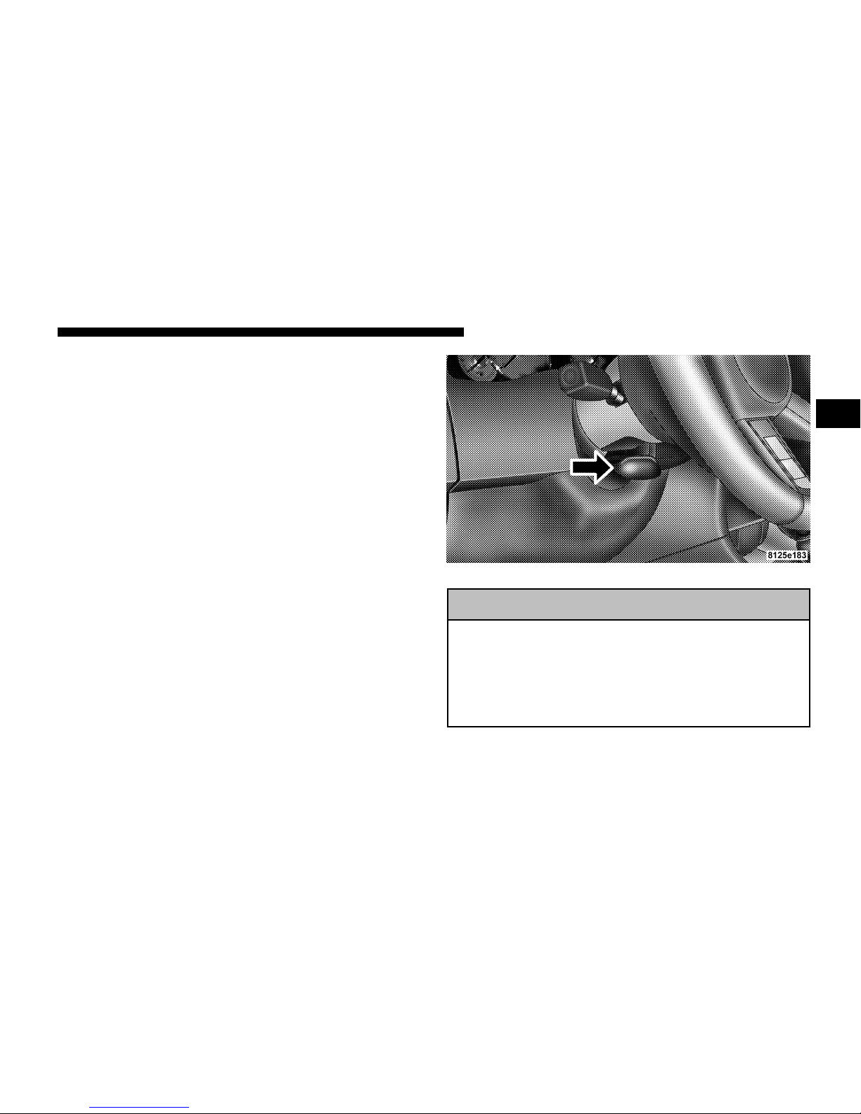
TILT STEERING COLUMN
The steering column equipped on this vehicle only tilts.
Unlock the steering column by pulling out the handle
located directly below the column. To tilt the column
move the steering wheel up or down as desired. Lock the
steering column in position by pushing the handle in
until it fully engages.
WARNING!
Do not adjust the steering wheel while driving. The
tilt adjustment must be locked while driving. Adjusting the steering wheel while driving, or driving
without the tilt adjustment locked could cause the
driver to lose control of the vehicle.
Tilt Steering Column Control
UNDERSTANDING THE FEATURES OF YOUR VEHICLE 7
2
STEALTH MODE
This vehicle is designed for periods of
surveillance. The dimmer control is
part of the headlamp switch, and is
located on the left side of the instrument panel. By rotating the dimmer
control to the extreme bottom “OFF”
position to “stealth mode”, all interior
illumination except for PRNDL,
odometer, and vehicle critical warning indicators will be
cancelled. The PRNDL and odometer will go to the
lowest legal limit.
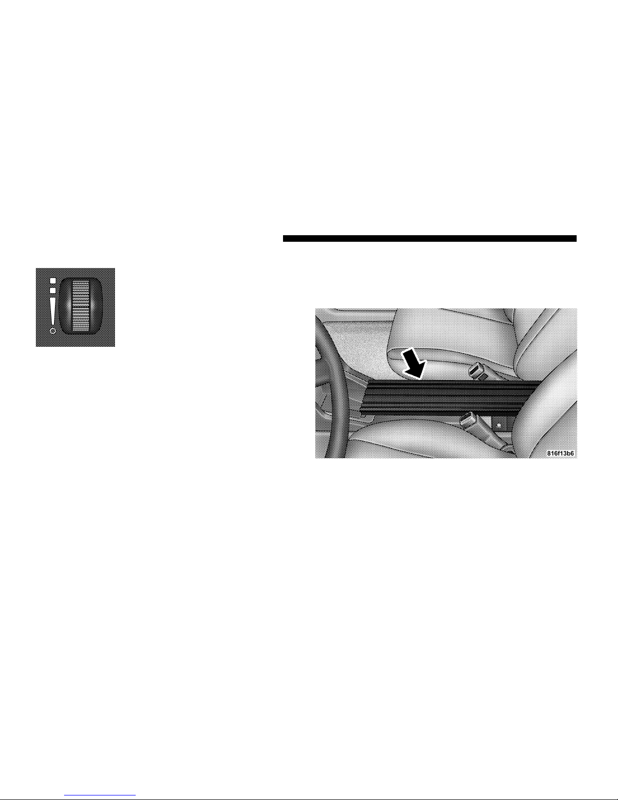
Equipment Mounting Bracket
The equipment mounting bracket is located between the
driver’s and front passenger’s seat. Refer to the Police
Upfitter’s Guide for details.
Dimmer Control
Equipment Mounting Bracket
8 UNDERSTANDING THE FEATURES OF YOUR VEHICLE
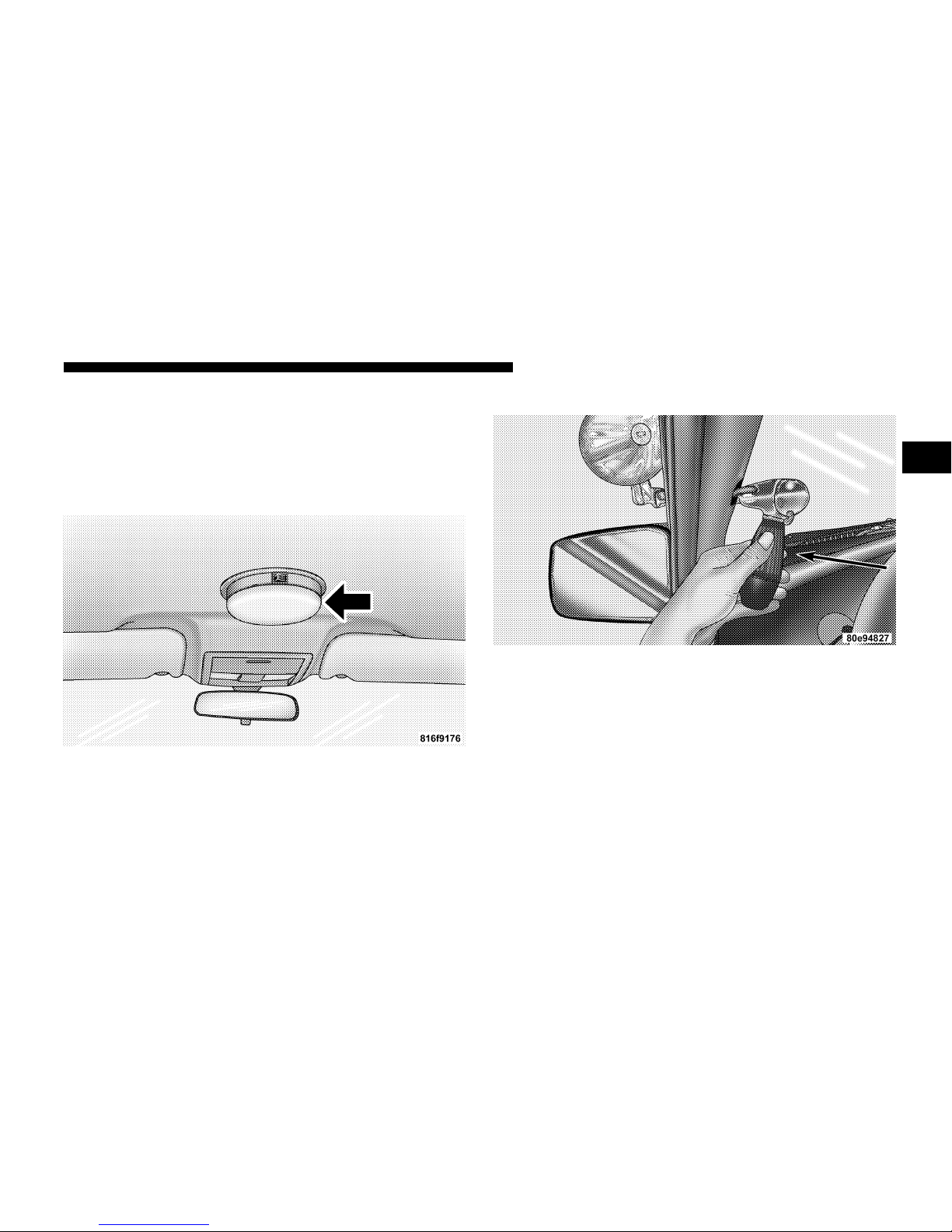
Police Dome Light — If Equipped
The police dome light switch has three positions. Position
I is used for white light, and position II is used for red
LED light. Always remember to return the dome light
switch to the OFF (center) position when finished using
to prevent discharging the vehicle battery.
SPOTLIGHTS — IF EQUIPPED
This vehicle may be equipped with up to two spotlights.
Each spotlight is attached to the A-Pillar. The spotlight
switch is located on the chrome section of the handle. Use
this switch to turn the spotlight on and off. Rotate and
twist the handle to adjust the position of the spotlight.
Dome Light
Spotlight Control
UNDERSTANDING THE FEATURES OF YOUR VEHICLE 9
2
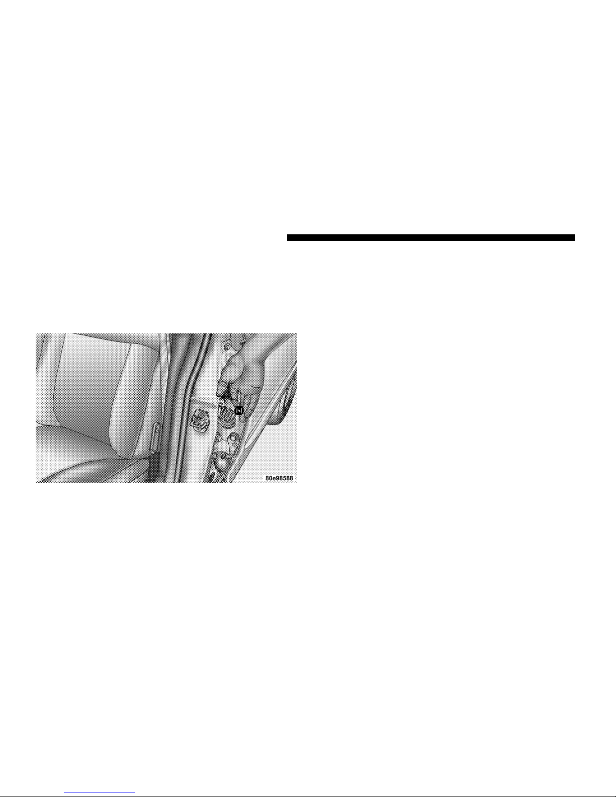
REMOTE REAR DOOR LOCKS — IF EQUIPPED
The emergency rear door lock knob is located in the front
portion of each rear door panel, visible when the front
door is opened. Pull out the knob to unlock the door. In
this same way the rear doors can be locked from the
outside of the vehicle by pushing the knob in.
Both rear passenger doors are inoperable from the rear
seat position inside the vehicle. There are three ways to
operate the rear door locks:
•
The driver door master door lock switch.
•
The remote keyless entry transmitter.
•
The emergency door lock knobs from outside of the
vehicle.
REAR WINDOWS — IF EQUIPPED
The rear windows are inoperable from the rear door
switches. Rear windows are only operable by the Driver
Door Master Switch.
AIRBAGS
Driver/passenger airbags affect the way police equipment can be safely mounted in police vehicles.
Any surfaces that could come into contact with an airbag,
once it has deployed, must not damage the airbag or alter
its deployment path.
The addition of any supplemental equipment (such as
radios, weapons, mounting brackets, cage, etc.), must be
installed such that it will not interfere or come in contact
with a deploying airbag. Airbag deployment zones are
described below. Sharp edges, corners, or protrusions on
supplemental equipment could damage the nylon airbag
material and reduce the effectiveness of the airbag during
a deployment.
Emergency Door Lock Knob
10 UNDERSTANDING THE FEATURES OF YOUR VEHICLE

WARNING!
• Installing a conventional police cage is not rec-
ommended on vehicles equipped with left and
right side curtain airbags, as police cages may
interfere with the deploying airbag. The area
where the side curtain airbag is located should
remain free from any obstructions.
• If your vehicle is equipped with left and right
side curtain airbags, do not have any accessory
items installed which will alter the roof, including adding a sunroof to your vehicle. Do not add
roof racks that require permanent attachments
(bolts or screws) for installation on the vehicle
roof. Do not drill into the roof of the vehicle for
any reason.
• Do not place objects or mount equipment in
front of the airbag module cover or in front of
the seat areas that may come in contact with a
deploying airbag. Failure to follow this instruction could result in personal injury.
• Dash, tunnel or console-mounted equipment
should not be placed outside of the specified
zone. Failure to follow this instruction could
result in personal injury.
AIRBAG DEPLOYMENT ZONES
There are three zones to be aware of:
1. Driver Airbag Deployment Zone (Fig. 1), (Fig. 2) and
Driver Airbag/Steering Wheel Specifications
2. Passenger Airbag Deployment Zone (Fig. 3) and (Fig.
4)
3. Side Airbag Deployment Zone (Fig. 5)
UNDERSTANDING THE FEATURES OF YOUR VEHICLE 11
2
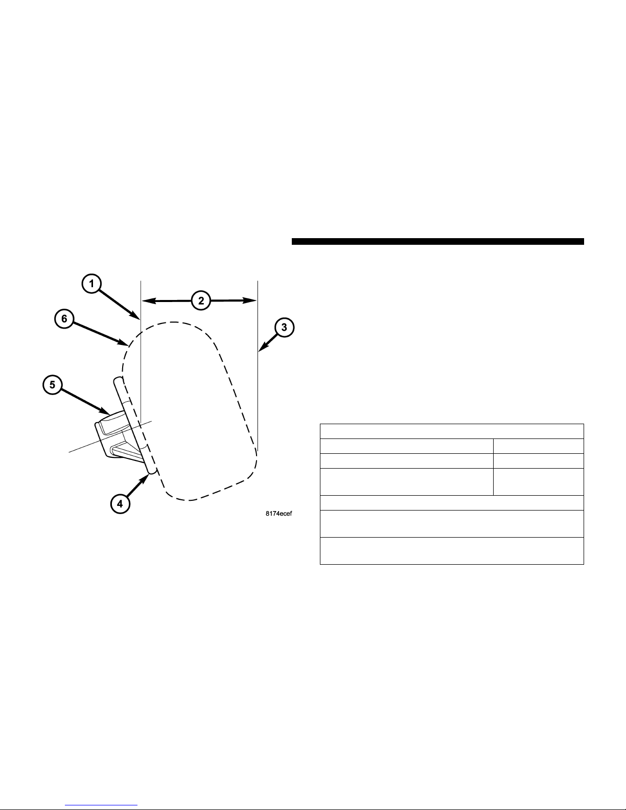
Figure 1– Driver Airbag Deployment Zone depicts the
following:
1. Vertical Plane Passing Through Center of Steering
Wheel
2. 18.7 inches
3. Vertical Plane Passing Through Maximum Rearward
Point That The Driver Airbag Cushion Reaches
4. Steering Wheel
5. Driver Airbag Retainer/Housing
6. Driver Airbag Cushion
DRIVER AIRBAG/STEERING COLUMN SPECIFICATIONS
DRIVER AIRBAG CUSHION POSITION
DAB DIAMETER WHEN FULL 26.5 INCHES
DAB DEPTH WHEN FULL 15 INCHES
MAXIMUM REARWARD DIS-
PLACEMENT DURING FILL
18.7 INCHES
STEERING COLUMN TILT POSITION RANGE
+/– 2.7 DEGREES FROM STEERING COLUMN TILT
PIVOT POINT
21.0 DEGREES FROM VERTICAL IS THE NOMINAL
POSITION
Figure 1
12 UNDERSTANDING THE FEATURES OF YOUR VEHICLE
 Loading...