

Page 1

DR DIFFERENTIAL & DRIVELINE 3 - 1
DIFFERENTIAL & DRIVELINE
TABLE OF CONTENTS
page page
DIFFERENTIAL & DRIVELINE - ELECTRICAL
DIAGNOSTICS ........................... 1
DIFFERENTIAL & DRIVELINE - SERVICE
INFORMATION......................... 113
DIFFERENTIAL & DRIVELINE - ELECTRICAL DIAGNOSTICS
TABLE OF CONTENTS
page page
DIFFERENTIAL & DRIVELINE - ELECTRICAL
DIAGNOSTICS
DIAGNOSIS AND TESTING
C143A - DIFFERENTIAL/LOCKER SELECT
SWITCH PERFORMANCE.....................3
C143B-DIFFERENTIAL/LOCKER SELECT
SWITCH CIRCUIT LOW.......................7
C143C-DIFFERENTIAL/LOCKER SELECT
SWITCH CIRCUIT HIGH.....................11
C1417–FRONT DIFFERENTIAL CONTROL
CIRCUIT LOW..............................15
C1418–FRONT DIFFERENTIAL CONTROL
CIRCUIT HIGH..............................19
C1419–FRONT DIFFERENTIAL CONTROL
CIRCUIT OPEN.............................23
C141D-REAR DIFFERENTIAL CONTROL
CIRCUIT LOW..............................26
C141E–REAR DIFFERENTIAL CONTROL
CIRCUIT HIGH..............................30
C141F–REAR DIFFERENTIAL CONTROL
CIRCUIT OPEN.............................34
C1446-FRONT DIFFERENTIAL RETURN
CIRCUIT LOW..............................37
C1447-FRONT DIFFERENTIAL RETURN
CIRCUIT HIGH..............................40
C144A-REAR DIFFERENTIAL RETURN
CIRCUIT LOW..............................44
C144B-REAR DIFFERENTIAL RETURN
CIRCUIT HIGH..............................47
C144E-FRONT DIFFERENTIAL POSITION
SENSOR PERFORMANCE...................51
C1450-FRONT DIFFERENTIAL POSITION
SENSOR CIRCUIT HIGH.....................55
C144F-FRONT DIFFERENTIAL POSITION
SENSOR LOW..............................59
C1452-REAR DIFFERENTIAL POSITION
SENSOR PERFORMANCE...................62
C1453-REAR DIFFERENTIAL POSITION
SENSOR LOW..............................66
C1454-REAR DIFFERENTIAL POSITION
SENSOR CIRCUIT HIGH.....................69
C2100–BATTERY VOLTAGE LOW ............73
C2101–BATTERY VOLTAGE HIGH ............76
C2111-SENSOR SUPPLY 1 VOLTAGE
CIRCUIT LOW..............................79
C2112-SENSOR SUPPLY 1 VOLTAGE
CIRCUIT HIGH..............................82
C2126-SENSOR SUPPLY 2 VOLTAGE
CIRCUIT LOW..............................85
C2127-SENSOR SUPPLY 2 VOLTAGE
CIRCUIT HIGH..............................88
C230F-LOCKER/DIFFERENTIAL INDICATOR
SUPPLY CIRCUIT PREFORMANCE...........91
C2310-STABILIZER/DIFFERENTIAL
INDICATOR SUPPLY CIRCUIT LOW..........95
C2311-STABILIZER/DIFFERENTIAL
INDICATOR SUPPLY CIRCUIT HIGH..........99
C2324-STABILIZER BAR INDICATOR
CONTROL CIRCUIT........................104
U0100-LOST COMMUNICATION WITH
ECM/PCM (FDCM).........................109
U0155-NO CLUSTER BUS MESSAGE ........111
Page 2

3 - 2 DIFFERENTIAL & DRIVELINE - ELECTRICAL DIAGNOSTICS DR
DIFFERENTIAL & DRIVELINE - ELECTRICAL DIAGNOSTICS
DIAGNOSIS AND TESTING
Page 3

DR DIFFERENTIAL & DRIVELINE - ELECTRICAL DIAGNOSTICS 3 - 3
C143A - DIFFERENTIAL/LOCKER SELECT SWITCH PERFORMANCE
For a complete wiring diagram Refer to Section 8W
Page 4

3 - 4 DIFFERENTIAL & DRIVELINE - ELECTRICAL DIAGNOSTICS DR
• When Monitored:
Ignition on.
• Set Condition:
During switch operation, the FDCM senses the Disconnecting Stabilizer Bar Switch resistance is out of specification.
Possible Causes
SWITCH INTERMITTENT
DISCONNECTING STABILIZER BAR SWITCH
(T537) LOCKER SWITCH SUPPLY CIRCUIT
(T535) LOCKER SWITCH SENSE CIRCUIT OPEN/HIGH RESISTANCE
FDCM
DTC ACTIVE
1.
CAUTION: Before removing the FDCM harness connector, clean the connector and locking cam area of dirt
and debris. Failure to do so can result in the connector being jammed or damage to the locking cams on
the harness connector or module. Do not force the assist arm when releasing or installing the harness connector.
Turn the ignition on, engine not running
With the scan tool, read FDCM DTC(s).
Is the DTC active at this time?
Yes >>
No >>
DISCONNECTING STABILIZER BAR SWITCH OPERATION
2.
NOTE: Before continuing with the below diagnostic test, ensure the FDCM harness connector seal is
installed correctly. Inspect the terminals on both harness connector and the module for damage. Failure to
do so can result in misdiagnoses of the system.
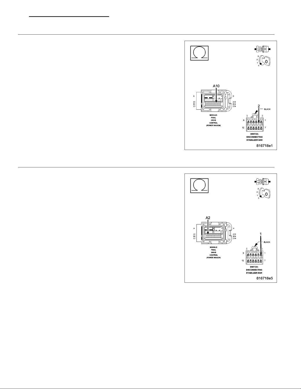
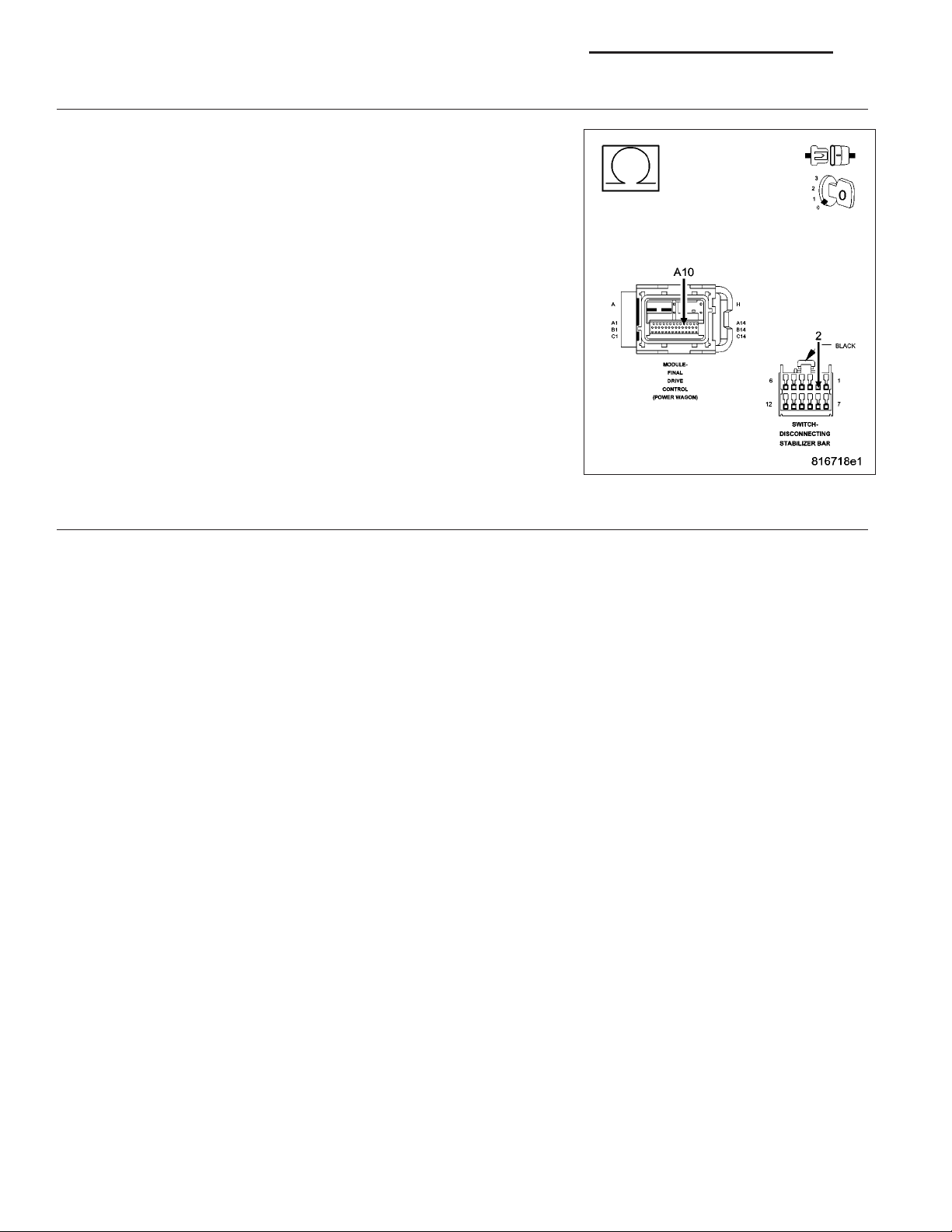
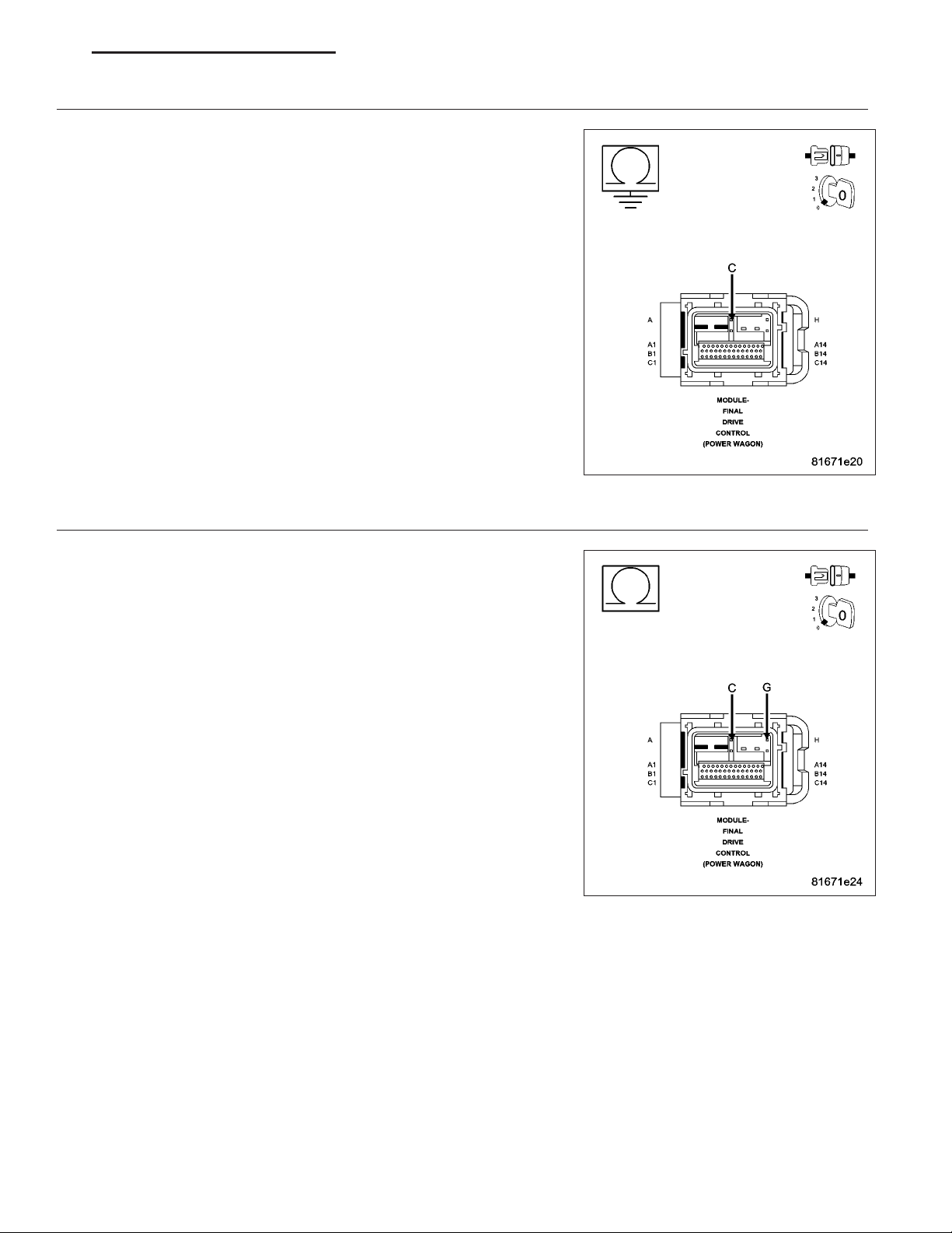
Turn the ignition off.
Disconnect the Disconnecting Stabilizer Bar Switch harness connector.
Remove the Disconnecting Stabilizer Bar Switch.
Measure the resistance on the Disconnecting Stabilizer Bar Switch between the Locker Switch Supply terminal and
the Locker Switch Sense terminal.
The resistance must read as follows for each position of the switch.
• UNLOCK: 5454 ohms +/- 5%
• RR: 1940 ohms +/- 5%
• FR/RR: 1075 ohms +/- 5%
Does the ohmmeter read correctly for each position of the Disconnecting Stabilizer Bar Switch
Yes >>
No >>
Go To 2
Go To 5
Go To 3
Replace the Disconnecting Stabilizer Bar Switch.
Perform FDCM VERIFICATION TEST. (Refer to 2 - SUSPENSION/ACTIVE CHASSIS - STANDARD
PROCEDURE)
Page 5
DR DIFFERENTIAL & DRIVELINE - ELECTRICAL DIAGNOSTICS 3 - 5
(T535) LOCKER SWITCH SENSE CIRCUIT OPEN
3.
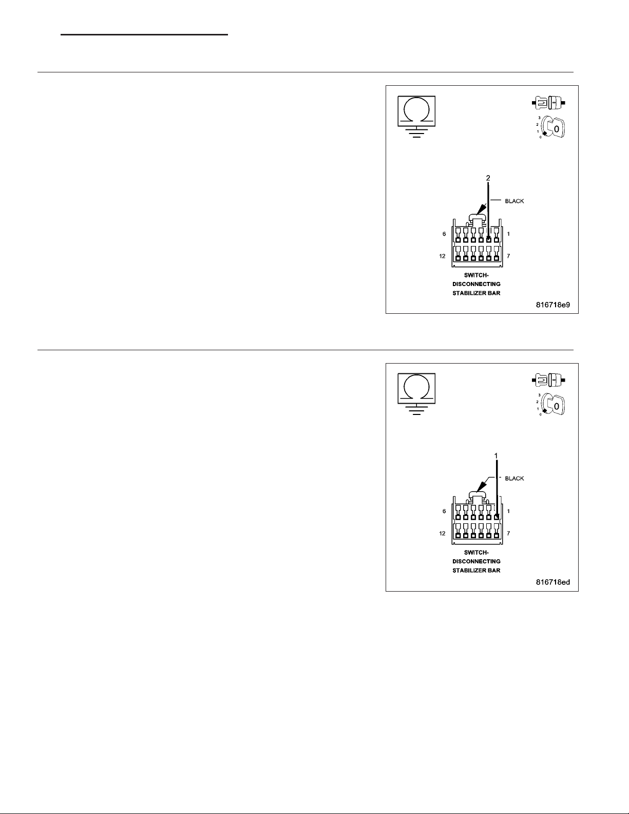
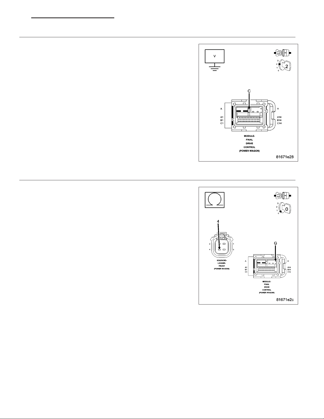
Disconnect the FDCM harness connector.
Measure the resistance of the (T535) Locker Switch Sense circuit
between the Disconnecting Stabilizer Bar Switch and the FDCM harness connector.
Is the resistance below 5.0 ohms?
Yes >>
No >>
(T537) LOCKER SWITCH SUPPLY CIRCUIT OPEN
4.
Measure the resistance of the (T537) Locker Switch Supply circuit
between the Disconnecting Stabilizer Bar Switch and the FDCM harness connector.
Is the resistance below 5.0 ohms?
Yes >>
No >>
Go To 4
Repair the open or high resistance in the (T535) Locker
Switch Sense circuit.
Perform FDCM VERIFICATION TEST. (Refer to 2 - SUS-
PENSION/ACTIVE CHASSIS - STANDARD PROCEDURE)
Replace the FDCM in accordance with the Service Information
Perform FDCM VERIFICATION TEST.
Repair the open or high resistance in the (T537) Locker
Switch Supply circuit.
Perform FDCM VERIFICATION TEST. (Refer to 2 - SUS-
PENSION/ACTIVE CHASSIS - STANDARD PROCEDURE)
Page 6

3 - 6 DIFFERENTIAL & DRIVELINE - ELECTRICAL DIAGNOSTICS DR
INTERMITTENT WIRING AND CONNECTORS
5.
The conditions necessary to set this DTC are not present at this time.
Using the schematics as a guide, inspect the wiring and connectors specific to this circuit.
Wiggle test the wiring harness and connectors while checking for shorted and open circuits.
Using the scan tool, monitor the data related to this circuit while performing the wiggle test. Look for the data to
change or for the DTC to reset.
While monitoring the TRAC State on the scan tool, move the switch to each position. The scan tool display must
match the position on the actual switch.
Were there any problems found?
Yes >>
No >>
Repair as necessary.
Perform FDCM VERIFICATION TEST. (Refer to 2 - SUSPENSION/ACTIVE CHASSIS - STANDARD
PROCEDURE)
Test Complete.
Page 7

DR DIFFERENTIAL & DRIVELINE - ELECTRICAL DIAGNOSTICS 3 - 7
C143B-DIFFERENTIAL/LOCKER SELECT SWITCH CIRCUIT LOW
For a complete wiring diagram Refer to Section 8W.
Page 8

3 - 8 DIFFERENTIAL & DRIVELINE - ELECTRICAL DIAGNOSTICS DR
• When Monitored:
Ignition on.
• Set Condition:
During switch operation, the FDCM senses the Disconnecting Stabilizer Bar Switch sense is below 0.25 volt.
Possible Causes
SWITCH INTERMITTENT
DISCONNECTING STABILIZER BAR SWITCH
(T537) LOCKER SWITCH SUPPLY CIRCUIT SHORTED TO GROUND
(T535) LOCKER SWITCH SENSE CIRCUIT SHORT TO GROUND
FDCM
DTC ACTIVE
1.
CAUTION: Before removing the FDCM harness connector, clean the connector and locking cam area of dirt
and debris. Failure to do so can result in the connector being jammed or damage to the locking cams on
the harness connector or module. Do not force the assist arm when releasing or installing the harness connector.
Turn the ignition on, engine not running
With the scan tool, read FDCM DTC(s).
Is the DTC active at this time?
Yes >>
No >>
DISCONNECTING STABILIZER BAR SWITCH OPERATION
2.
NOTE: Before continuing with the below diagnostic test, ensure the FDCM harness connector seal is
installed correctly. Inspect the terminals on both harness connector and the module for damage. Failure to
do so can result in misdiagnoses of the system.
Turn the ignition off.
Disconnect the Disconnecting Stabilizer Bar Switch harness connector.
Remove the Disconnecting Stabilizer Bar Switch.
Measure the resistance on the Disconnecting Stabilizer Bar Switch between the Locker Switch Supply terminal and
the Locker Switch Sense terminal.
The resistance must read as follows for each position of the switch.
• UNLOCK: 5454 ohms +/- 5%
• RR: 1940 ohms +/- 5%
• FR/RR: 1075 ohms +/- 5%
Does the ohmmeter read correctly for each position of the Disconnecting Stabilizer Bar Switch
Yes >>
No >>
Go To 2
Go To 5
Go To 3
Replace the Disconnecting Stabilizer Bar Switch.
Perform FDCM VERIFICATION TEST. (Refer to 2 - SUSPENSION/ACTIVE CHASSIS - STANDARD
PROCEDURE)
Page 9
DR DIFFERENTIAL & DRIVELINE - ELECTRICAL DIAGNOSTICS 3 - 9
(T535) LOCKER SWITCH SENSE CIRCUIT SHORTED TO GROUND
3.
Disconnect the FDCM harness connector.
Measure the resistance of the (T535) Locker Switch Sense circuit in the
Disconnecting Stabilizer Bar Switch harness connector to ground.
Is the resistance below 100 ohms?
Yes >>
No >>
(T537) LOCKER SWITCH SUPPLY CIRCUIT SHORT TO GROUND
4.
Measure the resistance of the (T537) Locker Switch Supply circuit in the
Disconnecting Stabilizer Bar Switch harness connector to ground.
Is the resistance below 100 ohms?
Yes >>
No >>
Repair the short to ground in the (T535) Locker Switch
Sense circuit.
Perform FDCM VERIFICATION TEST. (Refer to 2 - SUSPENSION/ACTIVE CHASSIS - STANDARD PROCEDURE)
Go To 4
Repair the short to ground in the (T537) Locker Switch Supply circuit.
Perform FDCM VERIFICATION TEST. (Refer to 2 - SUSPENSION/ACTIVE CHASSIS - STANDARD PROCEDURE)
Replace the FDCM in accordance with the Service Information
Perform FDCM VERIFICATION TEST. (Refer to 2 - SUSPENSION/ACTIVE CHASSIS - STANDARD PROCEDURE)
Page 10

3 - 10 DIFFERENTIAL & DRIVELINE - ELECTRICAL DIAGNOSTICS DR
INTERMITTENT WIRING AND CONNECTORS
5.
The conditions necessary to set this DTC are not present at this time.
Using the schematics as a guide, inspect the wiring and connectors specific to this circuit.
Wiggle test the wiring harness and connectors while checking for shorted and open circuits.
Using the scan tool, monitor the data related to this circuit while performing the wiggle test. Look for the data to
change or for the DTC to reset.
While monitoring the TRAC State on the scan tool, move the switch to each position. The scan tool display must
match the position on the actual switch.
Were there any problems found?
Yes >>
No >>
Repair as necessary.
Perform FDCM VERIFICATION TEST. (Refer to 2 - SUSPENSION/ACTIVE CHASSIS - STANDARD
PROCEDURE)
Test Complete.
Page 11

DR DIFFERENTIAL & DRIVELINE - ELECTRICAL DIAGNOSTICS 3 - 11
C143C-DIFFERENTIAL/LOCKER SELECT SWITCH CIRCUIT HIGH
For a complete wiring diagram Refer to Section 8W.
Page 12

3 - 12 DIFFERENTIAL & DRIVELINE - ELECTRICAL DIAGNOSTICS DR
• When Monitored:
Ignition on.
• Set Condition:
During switch operation, the FDCM senses the Disconnecting Stabilizer Bar Switch Sense circuit is above 4.5
volts.
Possible Causes
SWITCH INTERMITTENT
DISCONNECTING STABILIZER SWTICH
(T535) LOCKER SWITCH SENSE CIRCUIT SHORT TO VOLTAGE
(T537) LOCKER SWITCH SUPPLY CIRCUIT SHORTED TO (T535) LOCKER SWITCH SENSE CIRCUIT
(T535) LOCKER SWITCH SENSE CIRCUIT OPEN
FDCM
DTC ACTIVE
1.
CAUTION: Before removing the FDCM harness connector, clean the connector and locking cam area of dirt
and debris. Failure to do so can result in the connector being jammed or damage to the locking cams on
the harness connector or module. Do not force the assist arm when releasing or installing the harness connector.
Turn the ignition on, engine not running
With the scan tool, read FDCM DTC(s).
Is the DTC active at this time?
Yes >>
No >>
DISCONNECTING STABILIZER SWTICH OPERATION
2.
NOTE: Before continuing with the below diagnostic test, ensure the FDCM harness connector seal is
installed correctly. Inspect the terminals on both harness connector and the module for damage. Failure to
do so can result in misdiagnoses of the system.
Turn the ignition off.
Disconnect the Disconnecting Stabilizer Bar Switch harness connector.
Remove the Disconnecting Stabilizer Bar Switch.
Measure the resistance on the Disconnecting Stabilizer Bar Switch between the Locker Switch Supply terminal and
the Locker Switch Sense terminal.
The resistance must read as follows for each position of the switch.
• UNLOCK: 5454 ohms +/- 5%
• RR: 1940 ohms +/- 5%
• FR/RR: 1075 ohms +/- 5%
Does the ohmmeter read correctly for each position of the Disconnecting Stabilizer Bar Switch
Yes >>
No >>
Go To 2
Go To 6
Go To 3
Replace the Disconnecting Stabilizer Bar Switch.
Perform FDCM VERIFICATION TEST. (Refer to 2 - SUSPENSION/ACTIVE CHASSIS - STANDARD
PROCEDURE)
Page 13
DR DIFFERENTIAL & DRIVELINE - ELECTRICAL DIAGNOSTICS 3 - 13
(T535) LOCKER SWITCH SENSE CIRCUIT SHORTED TO VOLTAGE
3.
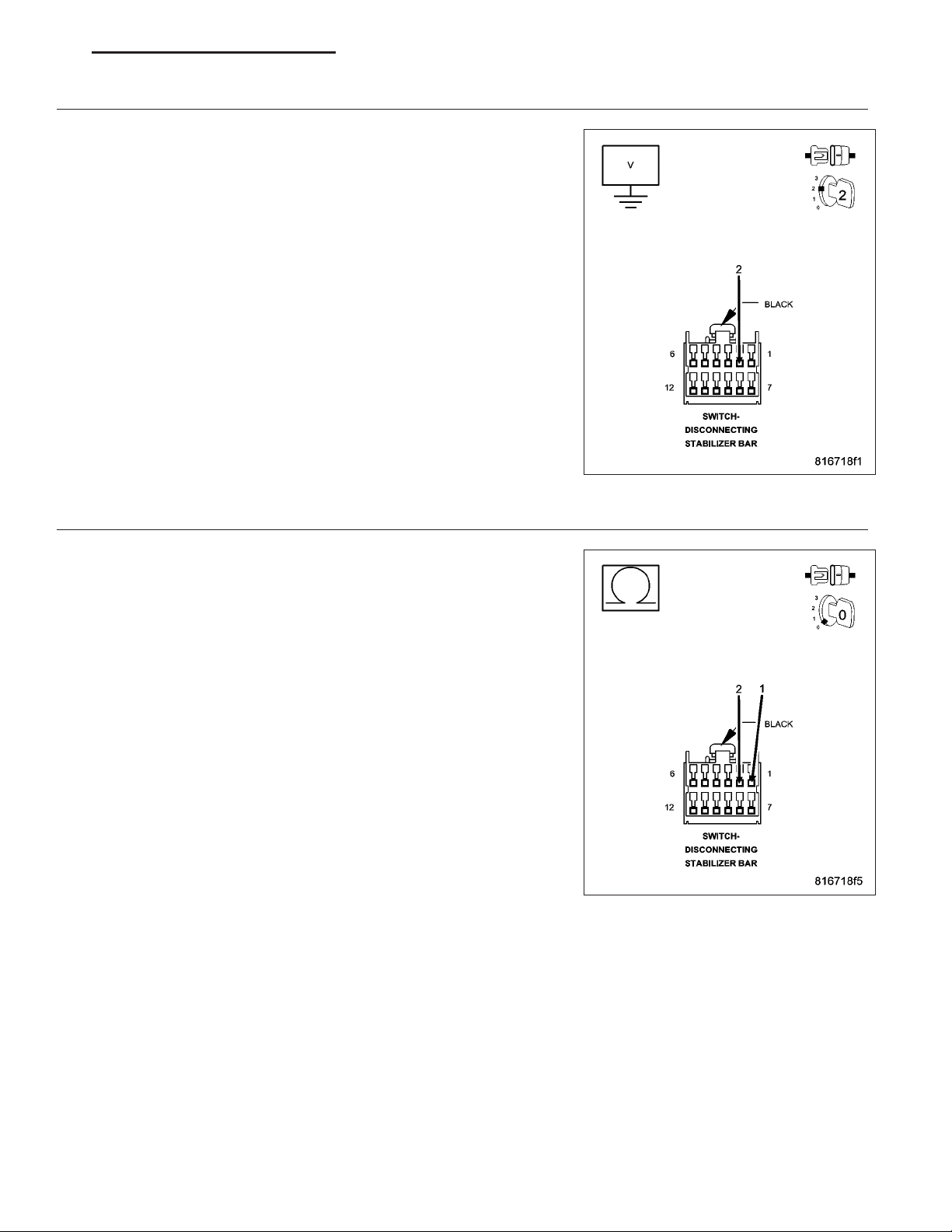
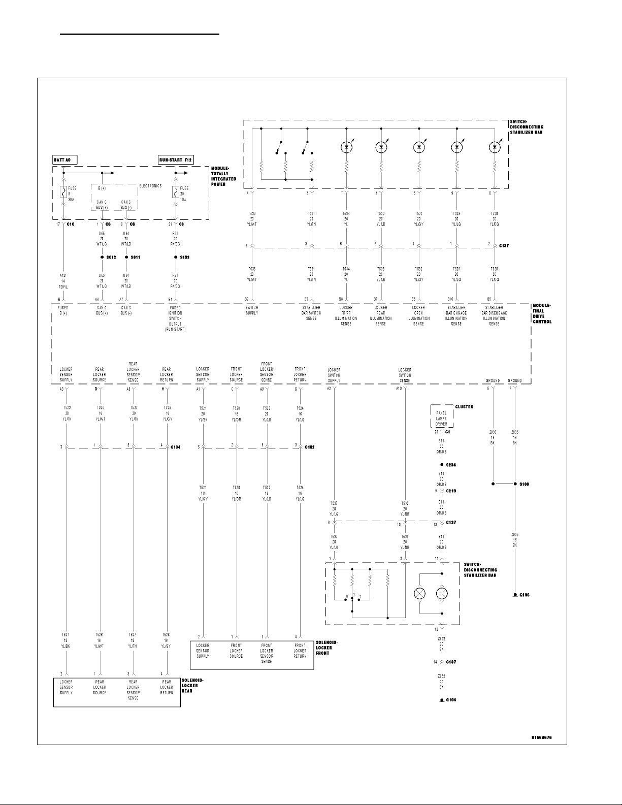
Disconnect the FDCM harness connector.
Turn the ignition on.
Measure the voltage of the (T535) Locker Switch Sense circuit in the
Disconnecting Stabilizer Bar Switch harness connector.
Does the voltmeter indicate voltage present?
Yes >>
No >>
(T537) LOCKER SWITCH SUPPLY CIRCUIT SHORTED TO (T535) LOCKER SWITCH SENSE CIRCUIT
4.
Measure the resistance between (T537) Locker Switch Supply circuit
and the (T535) Locker Switch Sense circuit in the Disconnecting Stabilizer Bar Switch harness connector.
Is the resistance below 5.0 ohms?
Yes >>
No >>
Repair the short to voltage in the (T535) Locker Switch
Sense circuit.
Perform FDCM VERIFICATION TEST. (Refer to 2 - SUSPENSION/ACTIVE CHASSIS - STANDARD PROCEDURE)
Go To 4
Repair the short between (T537) Locker Switch Supply circuit and the (T535) Locker Switch Sense circuit.
Perform FDCM VERIFICATION TEST. (Refer to 2 - SUSPENSION/ACTIVE CHASSIS - STANDARD PROCEDURE)
Go To 5
Page 14
3 - 14 DIFFERENTIAL & DRIVELINE - ELECTRICAL DIAGNOSTICS DR
(T535) LOCKER SWITCH SENSE CIRCUIT OPEN
5.
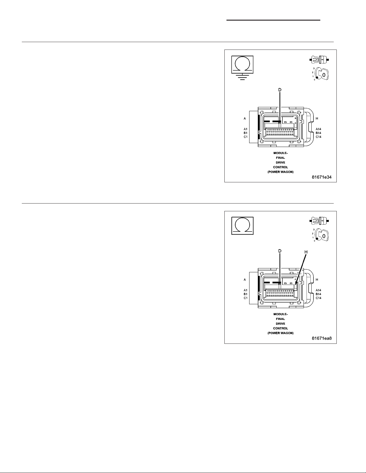
Measure the resistance of the (T535) Locker Switch Sense circuit
between the Disconnecting Stabilizer Bar Switch and the FDCM harness connector.
Is the resistance below 5.0 ohms?
Yes >>
No >>
INTERMITTENT WIRING AND CONNECTORS
6.
The conditions necessary to set this DTC are not present at this time.
Using the schematics as a guide, inspect the wiring and connectors specific to this circuit.
Wiggle test the wiring harness and connectors while checking for shorted and open circuits.
Using the scan tool, monitor the data related to this circuit while performing the wiggle test. Look for the data to
change or for the DTC to reset.
While monitoring the TRAC State on the scan tool, move the switch to each position. The scan tool display must
match the position on the actual switch.
Were there any problems found?
Replace the FDCM in accordance with the Service Information.
Perform FDCM VERIFICATION TEST. (Refer to 2 - SUSPENSION/ACTIVE CHASSIS - STANDARD PROCEDURE)
Repair the open in the (T535) Locker Switch Sense circuit.
Perform FDCM VERIFICATION TEST. (Refer to 2 - SUS-
PENSION/ACTIVE CHASSIS - STANDARD PROCEDURE)
Yes >>
No >>
Repair as necessary.
Perform FDCM VERIFICATION TEST. (Refer to 2 - SUSPENSION/ACTIVE CHASSIS - STANDARD
PROCEDURE)
Test Complete.
Page 15

DR DIFFERENTIAL & DRIVELINE - ELECTRICAL DIAGNOSTICS 3 - 15
C1417–FRONT DIFFERENTIAL CONTROL CIRCUIT LOW
For a complete wiring diagram Refer to Section 8W.
Page 16

3 - 16 DIFFERENTIAL & DRIVELINE - ELECTRICAL DIAGNOSTICS DR
• When Monitored:
Ignition on. Disconnecting Stabilizer Bar Switch in the FR/RR position.
• Set Condition:
The FDCM detects the Front Locker Source circuit is shorted low.
Possible Causes
FRONT LOCKER SOLENOID
(T520) FRONT LOCKER SOURCE CIRCUIT SHORTED TO GROUND
(T520) FRONT LOCKER SOURCE CIRCUIT SHORTED TO FRONT LOCKER RETURN CIRCUIT
FDCM
Diagnostic Test
ACTIVE DTC
1.
CAUTION: Before removing the FDCM harness connector, clean the connector and locking cam area of dirt
and debris. Failure to do so can result in the connector being jammed or damage to the locking cams on
the harness connector or module. Do not force the assist arm when releasing or installing the harness connector.
Ignition on, engine not running.
With the scan tool, read DTCs.
Is the DTC active at this time?
Yes >>
No >>
FRONT LOCKER SOLENOID OPERATION
2.
NOTE: Before continuing with the below diagnostic test, ensure the FDCM harness connector seal is
installed correctly. Inspect the terminals on both harness connector and the module for damage. Failure to
do so can result in misdiagnoses of the system.
Turn the ignition off.
Disconnect the Front Locker Solenoid harness connector.
Ignition on, engine not running.
Using a 12-volt test light, jump across from the (T520) Front Locker Source circuit and the (T524) Front Locker
Return circuit in the Front Locker harness connector.
With the scan tool, actuate the Front Locker Solenoid.
Does the test light illuminate and flash on and off?
Yes >>
No >>
Go To 2
Go To 6
Inspect the Front Locker Solenoid terminals and connectors for corrosion and/or dirt that may compromise the connection. If OK, replace the Front Locker Solenoid.
Perform FDCM VERIFICATION TEST. (Refer to 2 - SUSPENSION/ACTIVE CHASSIS - STANDARD
PROCEDURE)
Go To 3
Page 17
DR DIFFERENTIAL & DRIVELINE - ELECTRICAL DIAGNOSTICS 3 - 17
(T520) FRONT LOCKER SOURCE CIRCUIT SHORTED TO GROUND
3.
Turn the ignition off.
Disconnect the FDCM harness connector.
Measure the resistance of the (T520) Front Locker Source circuit at the
FDCM harness connector to ground.
Is the resistance below 100 ohms?
Yes >>
No >>
(T520) FRONT LOCKER SOURCE CIRCUIT SHORTED TO (T524) FRONT LOCKER RETURN CIRCUIT
4.
Measure the resistance between the (T520) Front Locker Source circuit
and the (T524) Front Locker Return circuit in the FDCM harness connector.
Is the resistance below 100 ohms?
Yes >>
No >>
Repair the short to ground in the Front Locker Source circuit.
Perform FDCM VERIFICATION TEST. (Refer to 2 - SUSPENSION/ACTIVE CHASSIS - STANDARD PROCEDURE)
Go To 4
Repair the short between (T520) Front Locker Source circuit
and the (T524) Front Locker Return circuit.
Perform FDCM VERIFICATION TEST. (Refer to 2 - SUSPENSION/ACTIVE CHASSIS - STANDARD PROCEDURE)
Go To 5
Page 18

3 - 18 DIFFERENTIAL & DRIVELINE - ELECTRICAL DIAGNOSTICS DR
FDCM
5.
NOTE: Before continuing, check the FDCM harness connector terminals for corrosion, damage, or terminal
push out. Repair as necessary.
Using the schematics as a guide, inspect the wire harness and connectors. Pay particular attention to all Power and
Ground circuits.
Were there any problems found?
Yes >>
No >>
INTERMITTENT WIRING AND CONNECTORS
6.
The conditions necessary to set this DTC are not present at this time.
Using the schematics as a guide, inspect the wiring and connectors specific to this circuit.
Wiggle test the wiring harness and connectors while checking for shorted and open circuits.
Using the scan tool, monitor the data related to this circuit while performing the wiggle test. Look for the data to
change or for the DTC to reset.
Were there any problems found?
Yes >>
No >>
Repair as necessary.
Perform FDCM VERIFICATION TEST. (Refer to 2 - SUSPENSION/ACTIVE CHASSIS - STANDARD
PROCEDURE)
Replace and program the Final Drive Control Module in accordance with Service Information.
Perform FDCM VERIFICATION TEST. (Refer to 2 - SUSPENSION/ACTIVE CHASSIS - STANDARD
PROCEDURE)
Repair as necessary.
Perform FDCM VERIFICATION TEST. (Refer to 2 - SUSPENSION/ACTIVE CHASSIS - STANDARD
PROCEDURE)
Test Complete.
Page 19

DR DIFFERENTIAL & DRIVELINE - ELECTRICAL DIAGNOSTICS 3 - 19
C1418–FRONT DIFFERENTIAL CONTROL CIRCUIT HIGH
For a complete wiring diagram Refer to Section 8W.
Page 20

3 - 20 DIFFERENTIAL & DRIVELINE - ELECTRICAL DIAGNOSTICS DR
• When Monitored:
Ignition on. Disconnecting Stabilizer Bar Switch the FR/RR position.
• Set Condition:
The FDCM detects the Front Locker Source circuit is shorted high.
Possible Causes
FRONT LOCKER SOLENOID
(T520) FRONT LOCKER SOURCE CIRCUIT SHORTED TO BATTERY VOLTAGE
(T524) FRONT LOCKER RETURN CIRCUIT OPEN
FDCM
Diagnostic Test
ACTIVE DTC
1.
CAUTION: Before removing the FDCM harness connector, clean the connector and locking cam area of dirt
and debris. Failure to do so can result in the connector being jammed or damage to the locking cams on
the harness connector or module. Do not force the assist arm when releasing or installing the harness connector.
Ignition on, engine not running.
With the scan tool, read DTCs.
Is the DTC active at this time?
Yes >>
No >>
FRONT LOCKER SOLENOID OPERATION
2.
NOTE: Before continuing with the below diagnostic test, ensure the FDCM harness connector seal is
installed correctly. Inspect the terminals on both harness connector and the module for damage. Failure to
do so can result in misdiagnoses of the system.
Turn the ignition off.
Disconnect the Front Locker Solenoid harness connector.
Ignition on, engine not running.
Using a 12-volt test light, jump across from the (T520) Front Locker Source circuit and the (T524) Front Locker
Return circuit in the Front Locker harness connector.
With a scan tool, actuate the Front Locker Solenoid.
Does the test light flash on and off?
Yes >>
No >>
Go To 2
Go To 6
Inspect the Front Locker Solenoid terminals and connectors for corrosion and/or dirt that may compromise the connection. If OK, replace the Front Locker Solenoid.
Perform FDCM VERIFICATION TEST. (Refer to 2 - SUSPENSION/ACTIVE CHASSIS - STANDARD
PROCEDURE)
Go To 3
Page 21
DR DIFFERENTIAL & DRIVELINE - ELECTRICAL DIAGNOSTICS 3 - 21
(T520) FRONT LOCKER SOURCE CIRCUIT SHORTED TO BATTERY VOLTAGE
3.
Turn the ignition off.
Disconnect the FDCM harness connector.
Turn the ignition on.
Measure the voltage on the (T520) Front Locker Source circuit at the
FDCM harness connector.
Does the voltmeter indicate voltage present?
Yes >>
No >>
(T524) FRONT LOCKER RETURN CIRCUIT OPEN
4.
Measure the resistance of the (T524) Front Locker Return circuit form
the in the Front Locker Solenoid harness connector and the FDCM harness connector.
Is the resistance below 5.0 ohms?
Yes >>
No >>
Repair the short to voltage in the (T520) Front Locker
Source circuit.
Perform FDCM VERIFICATION TEST. (Refer to 2 - SUSPENSION/ACTIVE CHASSIS - STANDARD PROCEDURE)
Go To 4
Go To 5
Repair the open in the (T524) Front Locker Return circuit.
Perform FDCM VERIFICATION TEST. (Refer to 2 - SUSPENSION/ACTIVE CHASSIS - STANDARD PROCEDURE)
Page 22

3 - 22 DIFFERENTIAL & DRIVELINE - ELECTRICAL DIAGNOSTICS DR
FDCM
5.
NOTE: Before continuing, check the FDCM harness connector terminals for corrosion, damage, or terminal
push out. Repair as necessary.
Using the schematics as a guide, inspect the wire harness and connectors. Pay particular attention to all Power and
Ground circuits.
Were there any problems found?
Yes >>
No >>
INTERMITTENT WIRING AND CONNECTORS
6.
The conditions necessary to set this DTC are not present at this time.
Using the schematics as a guide, inspect the wiring and connectors specific to this circuit.
Wiggle test the wiring harness and connectors while checking for shorted and open circuits.
Using the scan tool, monitor the data related to this circuit while performing the wiggle test. Look for the data to
change or for the DTC to reset.
Were there any problems found?
Yes >>
No >>
Repair as necessary.
Perform FDCM VERIFICATION TEST
Replace and program the Final Drive Control Module in accordance with Service Information.
Perform FDCM VERIFICATION TEST. (Refer to 2 - SUSPENSION/ACTIVE CHASSIS - STANDARD
PROCEDURE)
Repair as necessary.
Perform FDCM VERIFICATION TEST. (Refer to 2 - SUSPENSION/ACTIVE CHASSIS - STANDARD
PROCEDURE)
Test Complete.
Page 23
DR DIFFERENTIAL & DRIVELINE - ELECTRICAL DIAGNOSTICS 3 - 23
C1419–FRONT DIFFERENTIAL CONTROL CIRCUIT OPEN
For a complete wiring diagram Refer to Section 8W.
Page 24

3 - 24 DIFFERENTIAL & DRIVELINE - ELECTRICAL DIAGNOSTICS DR
• When Monitored:
Ignition on. Disconnecting Stabilizer Bar Switch in the FR/RR position.
• Set Condition:
The FDCM detects the Front Locker Source circuit is open.
Possible Causes
FRONT LOCKER SOLENOID
(T520) FRONT LOCKER SOURCE CIRCUIT OPEN
FDCM
Diagnostic Test
ACTIVE DTC
1.
CAUTION: Before removing the FDCM harness connector, clean the connector and locking cam area of dirt
and debris. Failure to do so can result in the connector being jammed or damage to the locking cams on
the harness connector or module. Do not force the assist arm when releasing or installing the harness connector.
Ignition on, engine not running.
With the scan tool, read DTCs.
Is the DTC active at this time?
Yes >>
No >>
FRONT LOCKER SOLENOID OPERATION
2.
NOTE: Before continuing with the below diagnostic test, ensure the FDCM harness connector seal is
installed correctly. Inspect the terminals on both harness connector and the module for damage. Failure to
do so can result in misdiagnoses of the system.
Turn the ignition off.
Disconnect the Front Locker Solenoid harness connector.
Ignition on, engine not running.
Using a 12-volt test light, jump across from the (T520) Front Locker Source circuit and the (T524) Front Locker
Return circuit in the Front Locker harness connector.
With a scan tool, actuate the Front Locker Solenoid.
Does the test light flash on and off?
Yes >>
No >>
Go To 2
Go To 5
Inspect the Front Locker Solenoid terminals and connectors for corrosion and/or dirt that may compromise the connection. If OK, replace the Front Locker Solenoid.
Perform FDCM VERIFICATION TEST. (Refer to 2 - SUSPENSION/ACTIVE CHASSIS - STANDARD
PROCEDURE)
Go To 3
Page 25

DR DIFFERENTIAL & DRIVELINE - ELECTRICAL DIAGNOSTICS 3 - 25
(T520) FRONT LOCKER SOURCE CIRCUIT OPEN
3.
Turn the ignition off.
Disconnect the FDCM harness connector.
Turn the ignition on.
Measure the resistance of the (T520) Front Locker Source circuit from
the FDCM harness connector and the Front Locker Solenoid harness
connector.
Is the resistances below 5.0 ohms?
Yes >>
No >>
FDCM
4.
NOTE: Before continuing, check the FDCM harness connector terminals for corrosion, damage, or terminal
push out. Repair as necessary.
Using the schematics as a guide, inspect the wire harness and connectors. Pay particular attention to all Power and
Ground circuits.
Were there any problems found?
Yes >>
No >>
Go To 4
Repair the open in the Front Locker Source circuit.
Perform FDCM VERIFICATION TEST. (Refer to 2 - SUSPENSION/ACTIVE CHASSIS - STANDARD PROCEDURE)
Repair as necessary.
Perform FDCM VERIFICATION TEST. (Refer to 2 - SUSPENSION/ACTIVE CHASSIS - STANDARD
PROCEDURE)
Replace and program the Final Drive Control Module in accordance with Service Information.
Perform FDCM VERIFICATION TEST. (Refer to 2 - SUSPENSION/ACTIVE CHASSIS - STANDARD
PROCEDURE)
INTERMITTENT WIRING AND CONNECTORS
5.
The conditions necessary to set this DTC are not present at this time.
Using the schematics as a guide, inspect the wiring and connectors specific to this circuit.
Wiggle test the wiring harness and connectors while checking for shorted and open circuits.
Using the scan tool, monitor the data related to this circuit while performing the wiggle test. Look for the data to
change or for the DTC to reset.
Were there any problems found?
Yes >>
No >>
Repair as necessary.
Perform FDCM VERIFICATION TEST. (Refer to 2 - SUSPENSION/ACTIVE CHASSIS - STANDARD
PROCEDURE)
Test Complete.
Page 26

3 - 26 DIFFERENTIAL & DRIVELINE - ELECTRICAL DIAGNOSTICS DR
C141D-REAR DIFFERENTIAL CONTROL CIRCUIT LOW
For a complete wiring diagram Refer to Section 8W.
Page 27

DR DIFFERENTIAL & DRIVELINE - ELECTRICAL DIAGNOSTICS 3 - 27
• When Monitored:
Ignition on. Disconnecting Stabilizer Bar Switch in the RR or FR/RR position.
• Set Condition:
The FDCM detects the Rear Locker Source circuit is shorted low.
Possible Causes
REAR LOCKER SOLENOID
(T526) REAR LOCKER SOURCE CIRCUIT SHORTED TO GROUND
(T528) REAR LOCKER SOURCE CIRCUIT SHORTED TO (T528) REAR LOCKER RETURN CIRCUIT
FDCM
Diagnostic Test
ACTIVE DTC
1.
CAUTION: Before removing the FDCM harness connector, clean the connector and locking cam area of dirt
and debris. Failure to do so can result in the connector being jammed or damage to the locking cams on
the harness connector or module. Do not force the assist arm when releasing or installing the harness connector.
Ignition on, engine not running.
With the scan tool, read DTCs.
Is the DTC active at this time?
Yes >>
No >>
REAR LOCKER SOLENOID OPERATION
2.
NOTE: Before continuing with the below diagnostic test, ensure the FDCM harness connector seal is
installed correctly. Inspect the terminals on both harness connector and the module for damage. Failure to
do so can result in misdiagnoses of the system.
Turn the ignition off.
Disconnect the Rear Locker Solenoid harness connector.
Ignition on, engine not running.
Using a 12-volt test light, jump across from the (T526) Rear Locker Source circuit and the (T528) Rear Locker
Return circuit in the Rear Locker harness connector.
With a scan tool, actuate the Rear Locker Solenoid.
Does the test light flash on and off?
Yes >>
No >>
Go To 2
Go To 6
Inspect the Rear Locker Solenoid terminals and connectors for corrosion and/or dirt that may compromise the connection. If OK, replace the Rear Locker Solenoid.
Perform FDCM VERIFICATION TEST. (Refer to 2 - SUSPENSION/ACTIVE CHASSIS - STANDARD
PROCEDURE)
Go To 3
Page 28
3 - 28 DIFFERENTIAL & DRIVELINE - ELECTRICAL DIAGNOSTICS DR
(T526) REAR LOCKER SOURCE CIRCUIT SHORTED TO GROUND
3.
Turn the ignition off.
Disconnect the FDCM harness connector.
Measure the resistance of the (T526) Rear Locker Source circuit at the
FDCM harness connector to ground.
Is the resistance below 100 ohms?
Yes >>
No >>
(T526) REAR LOCKER SOURCE CIRCUIT SHORTED TO (T528) REAR LOCKER RETURN CIRCUIT
4.
Measure the resistance between the (T526) Rear Locker Source circuit
and the (T528) Rear Locker Return circuit in the FDCM harness connector.
Is the resistance below 100 ohms?
Yes >>
No >>
Repair the short to ground in the Rear Locker Source circuit.
Perform FDCM VERIFICATION TEST. (Refer to 2 - SUSPENSION/ACTIVE CHASSIS - STANDARD PROCEDURE)
Go To 4
Repair the short between (T526) Rear Locker Source circuit
and the (T528) Rear Locker Return circuit.
Perform FDCM VERIFICATION TEST. (Refer to 2 - SUSPENSION/ACTIVE CHASSIS - STANDARD PROCEDURE)
Go To 5
Page 29

DR DIFFERENTIAL & DRIVELINE - ELECTRICAL DIAGNOSTICS 3 - 29
FDCM
5.
NOTE: Before continuing, check the FDCM harness connector terminals for corrosion, damage, or terminal
push out. Repair as necessary.
Using the schematics as a guide, inspect the wire harness and connectors. Pay particular attention to all Power and
Ground circuits.
Were there any problems found?
Yes >>
No >>
INTERMITTENT WIRING AND CONNECTORS
6.
The conditions necessary to set this DTC are not present at this time.
Using the schematics as a guide, inspect the wiring and connectors specific to this circuit.
Wiggle test the wiring harness and connectors while checking for shorted and open circuits.
Using the scan tool, monitor the data related to this circuit while performing the wiggle test. Look for the data to
change or for the DTC to reset.
Were there any problems found?
Yes >>
No >>
Repair as necessary.
Perform FDCM VERIFICATION TEST. (Refer to 2 - SUSPENSION/ACTIVE CHASSIS - STANDARD
PROCEDURE)
Replace and program the Final Drive Control Module in accordance with Service Information.
Perform FDCM VERIFICATION TEST. (Refer to 2 - SUSPENSION/ACTIVE CHASSIS - STANDARD
PROCEDURE)
Repair as necessary.
Perform FDCM VERIFICATION TEST. (Refer to 2 - SUSPENSION/ACTIVE CHASSIS - STANDARD
PROCEDURE)
Test Complete.
Page 30
3 - 30 DIFFERENTIAL & DRIVELINE - ELECTRICAL DIAGNOSTICS DR
C141E–REAR DIFFERENTIAL CONTROL CIRCUIT HIGH
For a complete wiring diagram Refer to Section 8W.
Page 31

DR DIFFERENTIAL & DRIVELINE - ELECTRICAL DIAGNOSTICS 3 - 31
• When Monitored:
Ignition on. Disconnecting Stabilizer Bar Switch in the FR/RR position.
• Set Condition:
The FDCM detects the Rear Locker Source circuit is shorted high.
Possible Causes
REAR LOCKER SOLENOID
(T526) REAR LOCKER SOURCE CIRCUIT SHORTED TO BATTERY VOLTAGE
(T528) REAR LOCKER RETURN CIRCUIT OPEN
FDCM
Diagnostic Test
ACTIVE DTC
1.
CAUTION: Before removing the FDCM harness connector, clean the connector and locking cam area of dirt
and debris. Failure to do so can result in the connector being jammed or damage to the locking cams on
the harness connector or module. Do not force the assist arm when releasing or installing the harness connector.
Ignition on, engine not running.
With the scan tool, read DTCs.
Is the DTC active at this time?
Yes >>
No >>
REAR LOCKER SOLENOID OPERATION
2.
NOTE: Before continuing with the below diagnostic test, ensure the FDCM harness connector seal is
installed correctly. Inspect the terminals on both harness connector and the module for damage. Failure to
do so can result in misdiagnoses of the system.
Turn the ignition off.
Disconnect the Rear Locker Solenoid harness connector.
Ignition on, engine not running.
Using a 12-volt test light, jump across from the (T526) Rear Locker Source circuit and the (T528) Rear Locker
Return circuit in the Rear Locker harness connector.
With a scan tool, actuate the Rear Locker Solenoid.
Does the test light flash on and off?
Yes >>
No >>
Go To 2
Go To 6
Inspect the Rear Locker Solenoid terminals and connectors for corrosion and/or dirt that may compromise the connection. If OK, replace the Rear Locker Solenoid.
Perform FDCM VERIFICATION TEST. (Refer to 2 - SUSPENSION/ACTIVE CHASSIS - STANDARD
PROCEDURE)
Go To 3
Page 32

3 - 32 DIFFERENTIAL & DRIVELINE - ELECTRICAL DIAGNOSTICS DR
(T526) REAR LOCKER SOURCE CIRCUIT SHORTED TO BATTERY VOLTAGE
3.
Turn the ignition off.
Disconnect the FDCM harness connector.
Turn the ignition on.
Measure the voltage on the (T526) Rear Locker Source circuit at the
FDCM harness connector.
Does the voltmeter indicate voltage present?
Yes >>
No >>
(T528) REAR LOCKER RETURN CIRCUIT OPEN
4.
Measure the resistance of the (T528) Rear Locker Return circuit form
the in the Rear Locker Solenoid harness connector and the FDCM harness connector.
Is the resistance below 5.0 ohms?
Yes >>
No >>
Repair the short to voltage in the (T526) Rear Locker
Source circuit.
Perform FDCM VERIFICATION TEST. (Refer to 2 - SUSPENSION/ACTIVE CHASSIS - STANDARD PROCEDURE)
Go To 4
Go To 5
Repair the open in the (T528) Rear Locker Return circuit.
Perform FDCM VERIFICATION TEST. (Refer to 2 - SUSPENSION/ACTIVE CHASSIS - STANDARD PROCEDURE)
Page 33

DR DIFFERENTIAL & DRIVELINE - ELECTRICAL DIAGNOSTICS 3 - 33
FDCM
5.
NOTE: Before continuing, check the FDCM harness connector terminals for corrosion, damage, or terminal
push out. Repair as necessary.
Using the schematics as a guide, inspect the wire harness and connectors. Pay particular attention to all Power and
Ground circuits.
Were there any problems found?
Yes >>
No >>
INTERMITTENT WIRING AND CONNECTORS
6.
The conditions necessary to set this DTC are not present at this time.
Using the schematics as a guide, inspect the wiring and connectors specific to this circuit.
Wiggle test the wiring harness and connectors while checking for shorted and open circuits.
Using the scan tool, monitor the data related to this circuit while performing the wiggle test. Look for the data to
change or for the DTC to reset.
Were there any problems found?
Yes >>
No >>
Repair as necessary.
Perform FDCM VERIFICATION TEST
Replace and program the Final Drive Control Module in accordance with Service Information.
Perform FDCM VERIFICATION TEST. (Refer to 2 - SUSPENSION/ACTIVE CHASSIS - STANDARD
PROCEDURE)
Repair as necessary.
Perform FDCM VERIFICATION TEST. (Refer to 2 - SUSPENSION/ACTIVE CHASSIS - STANDARD
PROCEDURE)
Test Complete.
Page 34

3 - 34 DIFFERENTIAL & DRIVELINE - ELECTRICAL DIAGNOSTICS DR
C141F–REAR DIFFERENTIAL CONTROL CIRCUIT OPEN
For a complete wiring diagram Refer to Section 8W.
Page 35

DR DIFFERENTIAL & DRIVELINE - ELECTRICAL DIAGNOSTICS 3 - 35
• When Monitored:
Ignition on. Disconnecting Stabilizer Bar Switch in the FR/RR position.
• Set Condition:
The FDCM detects the Rear Locker Source circuit is open.
Possible Causes
REAR LOCKER SOLENOID
(T526) REAR LOCKER SOURCE CIRCUIT OPEN
FDCM
Diagnostic Test
ACTIVE DTC
1.
CAUTION: Before removing the FDCM harness connector, clean the connector and locking cam area of dirt
and debris. Failure to do so can result in the connector being jammed or damage to the locking cams on
the harness connector or module. Do not force the assist arm when releasing or installing the harness connector.
Ignition on, engine not running.
With the scan tool, read DTCs.
Is the DTC active at this time?
Yes >>
No >>
REAR LOCKER SOLENOID OPERATION
2.
NOTE: Before continuing with the below diagnostic test, ensure the FDCM harness connector seal is
installed correctly. Inspect the terminals on both harness connector and the module for damage. Failure to
do so can result in misdiagnoses of the system.
Turn the ignition off.
Disconnect the Rear Locker Solenoid harness connector.
Ignition on, engine not running.
Using a 12-volt test light, jump across from the (T526) Rear Locker Source circuit and the (T528) Rear Locker
Return circuit in the Rear Locker harness connector.
With a scan tool, actuate the Rear Locker Solenoid.
Does the test light flash on and off?
Yes >>
No >>
Go To 2
Go To 5
Inspect the Rear Locker Solenoid terminals and connectors for corrosion and/or dirt that may compromise the connection. If OK, replace the Rear Locker Solenoid.
Perform FDCM VERIFICATION TEST. (Refer to 2 - SUSPENSION/ACTIVE CHASSIS - STANDARD
PROCEDURE)
Go To 3
Page 36

3 - 36 DIFFERENTIAL & DRIVELINE - ELECTRICAL DIAGNOSTICS DR
(T526) REAR LOCKER SOURCE CIRCUIT OPEN
3.
Turn the ignition off.
Disconnect the FDCM harness connector.
Turn the ignition on.
Measure the resistance of the (T526) Rear Locker Source circuit from
the FDCM harness connector and the Rear Locker Solenoid harness
connector.
Is the resistance below 5.0 ohms?
Yes >>
No >>
FDCM
4.
NOTE: Before continuing, check the FDCM harness connector terminals for corrosion, damage, or terminal
push out. Repair as necessary.
Using the schematics as a guide, inspect the wire harness and connectors. Pay particular attention to all Power and
Ground circuits.
Were there any problems found?
Yes >>
No >>
Go To 4
Repair the open in the Rear Locker Source circuit.
Perform FDCM VERIFICATION TEST. (Refer to 2 - SUSPENSION/ACTIVE CHASSIS - STANDARD PROCEDURE)
Repair as necessary.
Perform FDCM VERIFICATION TEST. (Refer to 2 - SUSPENSION/ACTIVE CHASSIS - STANDARD
PROCEDURE)
Replace and program the Final Drive Control Module in accordance with Service Information.
Perform FDCM VERIFICATION TEST. (Refer to 2 - SUSPENSION/ACTIVE CHASSIS - STANDARD
PROCEDURE)
INTERMITTENT WIRING AND CONNECTORS
5.
The conditions necessary to set this DTC are not present at this time.
Using the schematics as a guide, inspect the wiring and connectors specific to this circuit.
Wiggle test the wiring harness and connectors while checking for shorted and open circuits.
Using the scan tool, monitor the data related to this circuit while performing the wiggle test. Look for the data to
change or for the DTC to reset.
Were there any problems found?
Yes >>
No >>
Repair as necessary.
Perform FDCM VERIFICATION TEST. (Refer to 2 - SUSPENSION/ACTIVE CHASSIS - STANDARD
PROCEDURE)
Test Complete.
Page 37

DR DIFFERENTIAL & DRIVELINE - ELECTRICAL DIAGNOSTICS 3 - 37
C1446-FRONT DIFFERENTIAL RETURN CIRCUIT LOW
For a complete wiring diagram Refer to Section 8W.
Page 38

3 - 38 DIFFERENTIAL & DRIVELINE - ELECTRICAL DIAGNOSTICS DR
• When Monitored:
Ignition on. Disconnecting Stabilizer Bar Switch in the FR/RR position.
• Set Condition:
The FDCM detects the Front Locker Source circuit is shorted low.
Possible Causes
FRONT LOCKER SOLENOID
(T526) FRONT LOCKER RETURN CIRCUIT SHORTED TO GROUND
FDCM
Diagnostic Test
ACTIVE DTC
1.
CAUTION: Before removing the FDCM harness connector, clean the connector and locking cam area of dirt
and debris. Failure to do so can result in the connector being jammed or damage to the locking cams on
the harness connector or module. Do not force the assist arm when releasing or installing the harness connector.
Ignition on, engine not running.
With the scan tool, read DTCs.
Is the DTC active at this time?
Yes >>
No >>
FRONT LOCKER SOLENOID OPERATION
2.
NOTE: Before continuing with the below diagnostic test, ensure the FDCM harness connector seal is
installed correctly. Inspect the terminals on both harness connector and the module for damage. Failure to
do so can result in misdiagnoses of the system.
Turn the ignition off.
Disconnect the Front Locker Solenoid harness connector.
Ignition on, engine not running.
Using a 12-volt test light, jump across from the (T520) Front Locker Source circuit and the (T524) Front Locker
Return circuit in the Front Locker harness connector.
With a scan tool, actuate the Front Locker Solenoid.
Does the test light flash on and off?
Yes >>
No >>
Go To 2
Go To 5
Inspect the Front Locker Solenoid terminals and connectors for corrosion and/or dirt that may compromise the connection. If OK, replace the Front Locker Solenoid.
Perform FDCM VERIFICATION TEST. (Refer to 2 - SUSPENSION/ACTIVE CHASSIS - STANDARD
PROCEDURE)
Go To 3
Page 39

DR DIFFERENTIAL & DRIVELINE - ELECTRICAL DIAGNOSTICS 3 - 39
(T524) FRONT LOCKER RETURN CIRCUIT SHORTED TO GROUND
3.
Turn the ignition off.
Disconnect the FDCM harness connector.
Measure the resistance of the (T524) Front Locker Return circuit in the
FDCM harness connector to ground.
Is the resistance below 100 ohms?
Yes >>
No >>
FDCM
4.
NOTE: Before continuing, check the FDCM harness connector terminals for corrosion, damage, or terminal
push out. Repair as necessary.
Using the schematics as a guide, inspect the wire harness and connectors. Pay particular attention to all Power and
Ground circuits.
Were there any problems found?
Yes >>
No >>
Repair the short to ground in (T524) Front Locker Return
circuit.
Perform FDCM VERIFICATION TEST. (Refer to 2 - SUSPENSION/ACTIVE CHASSIS - STANDARD PROCEDURE)
Go To 4
Repair as necessary.
Perform FDCM VERIFICATION TEST. (Refer to 2 - SUSPENSION/ACTIVE CHASSIS - STANDARD
PROCEDURE)
Replace and program the Final Drive Control Module in accordance with Service Information.
Perform FDCM VERIFICATION TEST. (Refer to 2 - SUSPENSION/ACTIVE CHASSIS - STANDARD
PROCEDURE)
INTERMITTENT WIRING AND CONNECTORS
5.
The conditions necessary to set this DTC are not present at this time.
Using the schematics as a guide, inspect the wiring and connectors specific to this circuit.
Wiggle test the wiring harness and connectors while checking for shorted and open circuits.
Using the scan tool, monitor the data related to this circuit while performing the wiggle test. Look for the data to
change or for the DTC to reset.
Were there any problems found?
Yes >>
No >>
Repair as necessary.
Perform FDCM VERIFICATION TEST. (Refer to 2 - SUSPENSION/ACTIVE CHASSIS - STANDARD
PROCEDURE)
Test Complete.
Page 40

3 - 40 DIFFERENTIAL & DRIVELINE - ELECTRICAL DIAGNOSTICS DR
C1447-FRONT DIFFERENTIAL RETURN CIRCUIT HIGH
For a complete wiring diagram Refer to Section 8W.
Page 41

DR DIFFERENTIAL & DRIVELINE - ELECTRICAL DIAGNOSTICS 3 - 41
• When Monitored:
Ignition on. Disconnection Stabilizer Bar Switch in the FR/RR position.
• Set Condition:
The FDCM detects the Front Locker Source circuit is shorted low.
Possible Causes
FRONT LOCKER SOLENOID
(T520) FRONT LOCKER SOURCE CIRCUIT SHORTED TO GROUND
(T524) FRONT LOCKER RETURN CIRCUIT SHORTED TO (T520) FRONT LOCKER SOURCE CIRCUIT
FDCM
Diagnostic Test
ACTIVE DTC
1.
CAUTION: Before removing the FDCM harness connector, clean the connector and locking cam area of dirt
and debris. Failure to do so can result in the connector being jammed or damage to the locking cams on
the harness connector or module. Do not force the assist arm when releasing or installing the harness connector.
Ignition on, engine not running.
With thescan tool, read DTCs.
Is the DTC active at this time?
Yes >>
No >>
FRONT LOCKER SOLENOID OPERATION
2.
NOTE: Before continuing with the below diagnostic test, ensure the FDCM harness connector seal is
installed correctly. Inspect the terminals on both harness connector and the module for damage. Failure to
do so can result in misdiagnoses of the system.
Turn the ignition off.
Disconnect the Front Locker Solenoid harness connector.
Ignition on, engine not running.
Using a 12-volt test light, jump across from the (T520) Front Locker Source circuit and the (T524) Front Locker
Return circuit in the Front Locker harness connector.
With ascan tool, actuate the Front Locker Solenoid.
Does the test light flash on and off?
Yes >>
No >>
Go To 2
Go To 6
Inspect the Front Locker Solenoid terminals and connectors for corrosion and/or dirt that may compromise the connection. If OK, replace the Front Locker Solenoid.
Perform FDCM VERIFICATION TEST. (Refer to 2 - SUSPENSION/ACTIVE CHASSIS - STANDARD
PROCEDURE)
Go To 3
Page 42

3 - 42 DIFFERENTIAL & DRIVELINE - ELECTRICAL DIAGNOSTICS DR
(T524) FRONT LOCKER RETURN CIRCUIT SHORTED TO BATTERY VOLTAGE
3.
Turn the ignition off.
Disconnect the FDCM harness connector.
Turn the ignition on.
Measure the voltage of the (T524) Front Locker Return circuit at the
FDCM harness connector.
Does the voltmeter indicate voltage present?
Yes >>
No >>
(T524) FRONT LOCKER RETURN CIRCUIT SHORTED TO (T520) FRONT LOCKER SOURCE CIRCUIT
4.
Turn the ignition off.
Measure the resistance between the (T520) Front Locker Source circuit
and the (T524) Front Locker Return circuit in the FDCM harness connector.
Is the resistance below 100 ohms?
Yes >>
No >>
Repair the short to voltage in the (T524) Front Locker
Return circuit.
Perform FDCM VERIFICATION TEST. (Refer to 2 - SUSPENSION/ACTIVE CHASSIS - STANDARD PROCEDURE)
Go To 4
Repair the short between (T520) Front Locker Source circuit
and the (T524) Front Locker Return circuit.
Perform FDCM VERIFICATION TEST. (Refer to 2 - SUSPENSION/ACTIVE CHASSIS - STANDARD PROCEDURE)
Go To 5
Page 43

DR DIFFERENTIAL & DRIVELINE - ELECTRICAL DIAGNOSTICS 3 - 43
FDCM
5.
NOTE: Before continuing, check the FDCM harness connector terminals for corrosion, damage, or terminal
push out. Repair as necessary.
Using the schematics as a guide, inspect the wire harness and connectors. Pay particular attention to all Power and
Ground circuits.
Were there any problems found?
Yes >>
No >>
INTERMITTENT WIRING AND CONNECTORS
6.
The conditions necessary to set this DTC are not present at this time.
Using the schematics as a guide, inspect the wiring and connectors specific to this circuit.
Wiggle test the wiring harness and connectors while checking for shorted and open circuits.
Using the scan tool, monitor the data related to this circuit while performing the wiggle test. Look for the data to
change or for the DTC to reset.
Were there any problems found?
Yes >>
No >>
Repair as necessary.
Perform FDCM VERIFICATION TEST
Replace and program the Final Drive Control Module in accordance with Service Information.
Perform FDCM VERIFICATION TEST. (Refer to 2 - SUSPENSION/ACTIVE CHASSIS - STANDARD
PROCEDURE)
Repair as necessary.
Perform FDCM VERIFICATION TEST. (Refer to 2 - SUSPENSION/ACTIVE CHASSIS - STANDARD
PROCEDURE)
Test Complete.
Page 44

3 - 44 DIFFERENTIAL & DRIVELINE - ELECTRICAL DIAGNOSTICS DR
C144A-REAR DIFFERENTIAL RETURN CIRCUIT LOW
For a complete wiring diagram Refer to Section 8W.
Page 45

DR DIFFERENTIAL & DRIVELINE - ELECTRICAL DIAGNOSTICS 3 - 45
• When Monitored:
Ignition on. Disconnecting Stabilizer Bar Switch in the RR or FR/RR position.
• Set Condition:
The FDCM detects the Rear Locker Source circuit is shorted low.
Possible Causes
REAR LOCKER SOLENOID
(T528) REAR LOCKER RETURN CIRCUIT SHORTED TO GROUND
FDCM
Diagnostic Test
ACTIVE DTC
1.
CAUTION: Before removing the FDCM harness connector, clean the connector and locking cam area of dirt
and debris. Failure to do so can result in the connector being jammed or damage to the locking cams on
the harness connector or module. Do not force the assist arm when releasing or installing the harness connector.
Ignition on, engine not running.
With the scan tool, read DTCs.
Is the DTC active at this time?
Yes >>
No >>
REAR LOCKER SOLENOID OPERATION
2.
NOTE: Before continuing with the below diagnostic test, ensure the FDCM harness connector seal is
installed correctly. Inspect the terminals on both harness connector and the module for damage. Failure to
do so can result in misdiagnoses of the system.
Turn the ignition off.
Disconnect the Rear Locker Solenoid harness connector.
Ignition on, engine not running.
Using a 12-volt test light, jump across from the (T526) Rear Locker Source circuit and the (T528) Rear Locker
Return circuit in the Rear Locker harness connector.
With a scan tool, actuate the Rear Locker Solenoid.
Does the test light flash on and off?
Yes >>
No >>
Go To 2
Go To 5
Inspect the Rear Locker Solenoid terminals and connectors for corrosion and/or dirt that may compromise the connection. If OK, replace the Rear Locker Solenoid.
Perform FDCM VERIFICATION TEST. (Refer to 2 - SUSPENSION/ACTIVE CHASSIS - STANDARD
PROCEDURE)
Go To 3
Page 46

3 - 46 DIFFERENTIAL & DRIVELINE - ELECTRICAL DIAGNOSTICS DR
(T528) REAR LOCKER RETURN CIRCUIT SHORTED TO GROUND
3.
Turn the ignition off.
Disconnect the FDCM harness connector.
Measure the resistance of the (T528) Rear Locker Return circuit in the
FDCM harness connector to ground.
Is the resistance below 100 ohms?
Yes >>
No >>
FDCM
4.
NOTE: Before continuing, check the FDCM harness connector terminals for corrosion, damage, or terminal
push out. Repair as necessary.
Using the schematics as a guide, inspect the wire harness and connectors. Pay particular attention to all Power and
Ground circuits.
Were there any problems found?
Yes >>
No >>
Repair the short to ground in (T528) Rear Locker Return
circuit.
Perform FDCM VERIFICATION TEST. (Refer to 2 - SUSPENSION/ACTIVE CHASSIS - STANDARD PROCEDURE)
Go To 4
Repair as necessary.
Perform FDCM VERIFICATION TEST. (Refer to 2 - SUSPENSION/ACTIVE CHASSIS - STANDARD
PROCEDURE)
Replace and program the Final Drive Control Module in accordance with Service Information.
Perform FDCM VERIFICATION TEST. (Refer to 2 - SUSPENSION/ACTIVE CHASSIS - STANDARD
PROCEDURE)
INTERMITTENT WIRING AND CONNECTORS
5.
The conditions necessary to set this DTC are not present at this time.
Using the schematics as a guide, inspect the wiring and connectors specific to this circuit.
Wiggle test the wiring harness and connectors while checking for shorted and open circuits.
Using the scan tool, monitor the data related to this circuit while performing the wiggle test. Look for the data to
change or for the DTC to reset.
Were there any problems found?
Yes >>
No >>
Repair as necessary.
Perform FDCM VERIFICATION TEST. (Refer to 2 - SUSPENSION/ACTIVE CHASSIS - STANDARD
PROCEDURE)
Test Complete.
Page 47

DR DIFFERENTIAL & DRIVELINE - ELECTRICAL DIAGNOSTICS 3 - 47
C144B-REAR DIFFERENTIAL RETURN CIRCUIT HIGH
For a complete wiring diagram Refer to Section 8W.
Page 48

3 - 48 DIFFERENTIAL & DRIVELINE - ELECTRICAL DIAGNOSTICS DR
• When Monitored:
Ignition on. Disconnecting Stabilizer Bar Switch in the RR or FR/RR position.
• Set Condition:
The FDCM detects the Rear Locker Source circuit is shorted low.
Possible Causes
REAR LOCKER SOLENOID
(T526) REAR LOCKER SOURCE CIRCUIT SHORTED TO GROUND
(T528) REAR LOCKER RETURN CIRCUIT SHORTED TO (T526) REAR LOCKER SOURCE CIRCUIT
FDCM
Diagnostic Test
ACTIVE DTC
1.
CAUTION: Before removing the FDCM harness connector, clean the connector and locking cam area of dirt
and debris. Failure to do so can result in the connector being jammed or damage to the locking cams on
the harness connector or module. Do not force the assist arm when releasing or installing the harness connector.
Ignition on, engine not running.
With the scan tool, read DTCs.
Is the DTC active at this time?
Yes >>
No >>
REAR LOCKER SOLENOID OPERATION
2.
NOTE: Before continuing with the below diagnostic test, ensure the FDCM harness connector seal is
installed correctly. Inspect the terminals on both harness connector and the module for damage. Failure to
do so can result in misdiagnoses of the system.
Turn the ignition off.
Disconnect the Rear Locker Solenoid harness connector.
Ignition on, engine not running.
Using a 12-volt test light, jump across from the (T526) Rear Locker Source circuit and the (T528) Rear Locker
Return circuit in the Rear Locker harness connector.
With a scan tool, actuate the Rear Locker Solenoid.
Does the test light flash on and off?
Yes >>
No >>
Go To 2
Go To 6
Inspect the Rear Locker Solenoid terminals and connectors for corrosion and/or dirt that may compromise the connection. If OK, replace the Rear Locker Solenoid.
Perform FDCM VERIFICATION TEST. (Refer to 2 - SUSPENSION/ACTIVE CHASSIS - STANDARD
PROCEDURE)
Go To 3
Page 49

DR DIFFERENTIAL & DRIVELINE - ELECTRICAL DIAGNOSTICS 3 - 49
(T528) REAR LOCKER RETURN CIRCUIT SHORTED TO BATTERY VOLTAGE
3.
Turn the ignition off.
Disconnect the FDCM harness connector.
Turn the ignition on.
Measure the voltage of the (T528) Rear Locker Return circuit at the
FDCM harness connector.
Does the voltmeter indicate voltage present?
Yes >>
No >>
(T528) REAR LOCKER RETURN CIRCUIT SHORTED TO (T526) REAR LOCKER SOURCE CIRCUIT
4.
Turn the ignition off.
Measure the resistance between the (T526) Rear Locker Source circuit
and the (T528) Rear Locker Return circuit in the FDCM harness connector.
Is the resistance below 100 ohms?
Yes >>
No >>
Repair the short to voltage in the (T528) Rear Locker
Return circuit.
Perform FDCM VERIFICATION TEST. (Refer to 2 - SUSPENSION/ACTIVE CHASSIS - STANDARD PROCEDURE)
Go To 4
Repair the short between (T526) Rear Locker Source circuit
and the (T528) Rear Locker Return circuit.
Perform FDCM VERIFICATION TEST. (Refer to 2 - SUSPENSION/ACTIVE CHASSIS - STANDARD PROCEDURE)
Go To 5
Page 50

3 - 50 DIFFERENTIAL & DRIVELINE - ELECTRICAL DIAGNOSTICS DR
FDCM
5.
NOTE: Before continuing, check the FDCM harness connector terminals for corrosion, damage, or terminal
push out. Repair as necessary.
Using the schematics as a guide, inspect the wire harness and connectors. Pay particular attention to all Power and
Ground circuits.
Were there any problems found?
Yes >>
No >>
INTERMITTENT WIRING AND CONNECTORS
6.
The conditions necessary to set this DTC are not present at this time.
Using the schematics as a guide, inspect the wiring and connectors specific to this circuit.
Wiggle test the wiring harness and connectors while checking for shorted and open circuits.
Using the scan tool, monitor the data related to this circuit while performing the wiggle test. Look for the data to
change or for the DTC to reset.
Were there any problems found?
Yes >>
No >>
Repair as necessary.
Perform FDCM VERIFICATION TEST. (Refer to 2 - SUSPENSION/ACTIVE CHASSIS - STANDARD
PROCEDURE)
Replace and program the Final Drive Control Module in accordance with Service Information.
Perform FDCM VERIFICATION TEST. (Refer to 2 - SUSPENSION/ACTIVE CHASSIS - STANDARD
PROCEDURE)
Repair as necessary.
Perform FDCM VERIFICATION TEST. (Refer to 2 - SUSPENSION/ACTIVE CHASSIS - STANDARD
PROCEDURE)
Test Complete.
Page 51

DR DIFFERENTIAL & DRIVELINE - ELECTRICAL DIAGNOSTICS 3 - 51
C144E-FRONT DIFFERENTIAL POSITION SENSOR PERFORMANCE
For a complete wiring diagram Refer to Section 8W.
Page 52

3 - 52 DIFFERENTIAL & DRIVELINE - ELECTRICAL DIAGNOSTICS DR
• When Monitored:
The ignition on. Disconnecting Stabilizer Bar Switch in the FR/RR position.
• Set Condition:
The FDCM detects that the Front Differential Position Sensor is in an unexpected state.
Possible Causes
(T522) FRONT DIFFERENTIAL POSITION SENSOR (WIRING, CONNECTOR AND/OR TERMINAL CONDITION)
FRONT DIFFERENTIAL POSITION SENSOR
(T522) FRONT LOCKER SENSOR SENSE OPEN
FDCM
Diagnostic Test
ACTIVE DTC
1.
CAUTION: Before removing the FDCM harness connector, clean the connector and locking cam area of dirt
and debris. Failure to do so can result in the connector being jammed or damage to the locking cams on
the harness connector or module. Do not force the assist arm when releasing or installing the harness connector.
Ignition on, engine not running.
With the scan tool, read DTCs.
Is the DTC active at this time?
Yes >>
No >>
FRONT DIFFERENTIAL POSITION SENSOR WIRING
2.
NOTE: Before continuing with the below diagnostic test, ensure the FDCM harness connector seal is
installed correctly. Inspect the terminals on both harness connector and the module for damage. Failure to
do so can result in misdiagnoses of the system.
Using the scan tool, actuate the Front Locker Solenoid.
Monitor the Front Differential Position Sensor State.
Wiggle the related wiring harness from the FDCM to the Front Locker Solenoid connector at the axle.
With a scan tool, actuate the Front Locker Solenoid.
Does the state on the scan tool change while wiggling the wiring harness?
Yes >>
No >>
Go To 2
Go To 6
Using the schematics as a guide, inspect the wiring and connectors specific to this circuit. Check the
Locker Solenoid terminals and connectors for corrosion and/or dirt that may compromise the connection.
Repair as necessary.
Perform FDCM VERIFICATION TEST. (Refer to 2 - SUSPENSION/ACTIVE CHASSIS - STANDARD
PROCEDURE)
Go To 3
Page 53

DR DIFFERENTIAL & DRIVELINE - ELECTRICAL DIAGNOSTICS 3 - 53
FRONT DIFFERENTIAL POSITION SENSOR OPERATION
3.
Turn the ignition off.
Disconnect the Front Locker Solenoid harness connector.
Ignition on, engine not running.
Using a jumper wire, jumper across from the (T522) Front Locker Sensor Sense circuit and the (T521) Locker Sen-
sor Supply circuit in the Front Locker Solenoid harness connector.
While monitoring the sensor state on the scan tool, tap the jumper wire on and off the (T522) Front Locker Sensor
Sense circuit terminal. Hold the jumper wire on and off the terminal for a minimum of 3 seconds.
Does the state change on the scan tool while tapping the terminal?
Yes >>
No >>
(T522) FRONT LOCKER SENSOR SENSE CIRCUIT OPEN
4.
Turn the ignition off.
Disconnect the FDCM harness connector.
Measure the resistance of the (T522) Front Locker Sensor Sense circuit
between the Front Locker Solenoid harness connector and the FDCM
harness connector.
Is the resistance below 5.0 ohms?
Yes >>
No >>
Replace the Front Locker Solenoid.
Perform FDCM VERIFICATION TEST. (Refer to 2 - SUSPENSION/ACTIVE CHASSIS - STANDARD
PROCEDURE)
Go To 4
Go To 5
Repair the open in the Front Locker Sensor Sense circuit.
Perform FDCM VERIFICATION TEST. (Refer to 2 - SUSPENSION/ACTIVE CHASSIS - STANDARD PROCEDURE)
FDCM
5.
NOTE: Before continuing, check the FDCM harness connector terminals for corrosion, damage, or terminal
push out. Repair as necessary.
Using the schematics as a guide, inspect the wire harness and connectors. Pay particular attention to all Power and
Ground circuits.
Were there any problems found?
Yes >>
No >>
Repair as necessary.
Perform FDCM VERIFICATION TEST. (Refer to 2 - SUSPENSION/ACTIVE CHASSIS - STANDARD
PROCEDURE)
Replace and program the Final Drive Control Module in accordance with Service Information.
Perform FDCM VERIFICATION TEST. (Refer to 2 - SUSPENSION/ACTIVE CHASSIS - STANDARD
PROCEDURE)
Page 54

3 - 54 DIFFERENTIAL & DRIVELINE - ELECTRICAL DIAGNOSTICS DR
INTERMITTENT WIRING AND CONNECTORS
6.
The conditions necessary to set this DTC are not present at this time.
Using the schematics as a guide, inspect the wiring and connectors specific to this circuit.
Wiggle test the wiring harness and connectors while checking for shorted and open circuits.
Using the scan tool, monitor the data related to this circuit while performing the wiggle test. Look for the data to
change or for the DTC to reset.
Were there any problems found?
Yes >>
No >>
Repair as necessary.
Perform FDCM VERIFICATION TEST. (Refer to 2 - SUSPENSION/ACTIVE CHASSIS - STANDARD
PROCEDURE)
Test Complete.
Page 55

DR DIFFERENTIAL & DRIVELINE - ELECTRICAL DIAGNOSTICS 3 - 55
C1450-FRONT DIFFERENTIAL POSITION SENSOR CIRCUIT HIGH
For a complete wiring diagram Refer to Section 8W.
Page 56

3 - 56 DIFFERENTIAL & DRIVELINE - ELECTRICAL DIAGNOSTICS DR
• When Monitored:
Ignition on. Disconnecting Stabilizer Bar Switch in the FR/RR position.
• Set Condition:
The FDCM detects that the Front Differential Position Sensor is shorted to voltage.
Possible Causes
(T522) FRONT LOCKER SENSOR SENSE SHORTED TO BATTERY VOLTAGE
FRONT DIFFERENTIAL POSITION SENSOR
(T522) FRONT LOCKER SENSOR SENSE OPEN
(T522) FRONT LOCKER SENSOR SENSE SHORTED TO (T521) LOCKER SENSOR SUPPLY
FDCM
Diagnostic Test
ACTIVE DTC
1.
CAUTION: Before removing the FDCM harness connector, clean the connector and locking cam area of dirt
and debris. Failure to do so can result in the connector being jammed or damage to the locking cams on
the harness connector or module. Do not force the assist arm when releasing or installing the harness connector.
Ignition on, engine not running.
With the scan tool, read DTCs.
Is the DTC active at this time?
Yes >>
No >>
(T522) FRONT LOCKER SENSOR SENSE SHORTED TO BATTERY VOLTAGE
2.
NOTE: Before continuing with the below diagnostic test, ensure
the FDCM harness connector seal is installed correctly. Inspect the
terminals on both harness connector and the module for damage.
Failure to do so can result in misdiagnoses of the system.
Turn the ignition off.
Disconnect the Front Locker Solenoid harness connector.
Disconnect the FDCM harness connector.
Turn the ignition on.
Measure the voltage on the (T522) Front Locker Sensor Sense circuit in
the FDCM harness connector.
Does the voltmeter indicate voltage present?
Yes >>
No >>
Go To 2
Go To 7
Repair the short to voltage in the (T522) Front Locker Sensor Sense circuit.
Perform FDCM VERIFICATION TEST. (Refer to 2 - SUSPENSION/ACTIVE CHASSIS - STANDARD PROCEDURE)
Go To 3
Page 57

DR DIFFERENTIAL & DRIVELINE - ELECTRICAL DIAGNOSTICS 3 - 57
FRONT DIFFERENTIAL POSITION SENSOR OPERATION
3.
Turn the ignition off.
Connect the FDCM harness connector.
Ignition on, engine not running.
Using a jumper wire, jumper across from the (T522) Front Locker Sensor Sense circuit and the (T521) Locker Sen-
sor Supply circuit in the Front Locker Solenoid harness connector.
While monitoring the sensor state on the scan tool, tap the jumper wire on and off the (T522) Front Locker Sensor
Sense circuit terminal. Hold the jumper wire on and off the terminal for a minimum of 3 seconds.
Does the state change on the scan tool while tapping the terminal?
Yes >>
No >>
(T522) FRONT LOCKER SENSOR SENSE CIRCUIT OPEN
4.
Turn the ignition off.
Disconnect the FDCM harness connector.
Measure the resistance of the (T522) Front Locker Sensor Sense circuit
between the Front Locker Solenoid harness connector and the FDCM
harness connector.
Is the resistance below 5.0 ohms?
Yes >>
No >>
Replace the Front Locker Solenoid.
Perform FDCM VERIFICATION TEST. (Refer to 2 - SUSPENSION/ACTIVE CHASSIS - STANDARD
PROCEDURE)
Go To 4
Go To 5
Repair the open in the (T522) Front Locker Sensor Sense
circuit.
Perform FDCM VERIFICATION TEST. (Refer to 2 - SUS-
PENSION/ACTIVE CHASSIS - STANDARD PROCEDURE)
Page 58

3 - 58 DIFFERENTIAL & DRIVELINE - ELECTRICAL DIAGNOSTICS DR
(T522) FRONT LOCKER SENSOR SENSE CIRCUIT SHORTED TO (T521) LOCKER SENSOR 1 SUPPLY
5.
Measure the resistance between the (T522) Front Locker Sensor Sense
circuit and the (T521) Locker Sensor 1 Supply circuit in the FDCM harness connector.
Is the resistance below 5.0 ohms?
Yes >>
No >>
FDCM
6.
NOTE: Before continuing, check the FDCM harness connector terminals for corrosion, damage, or terminal
push out. Repair as necessary.
Using the schematics as a guide, inspect the wire harness and connectors. Pay particular attention to all Power and
Ground circuits.
Were there any problems found?
Yes >>
No >>
Repair the short between the (T522) Front Locker Sensor
Sense circuit and the (T521) Locker Sensor 1 Supply circuit.
Perform FDCM VERIFICATION TEST. (Refer to 2 - SUSPENSION/ACTIVE CHASSIS - STANDARD PROCEDURE)
Go To 6
Repair as necessary.
Perform FDCM VERIFICATION TEST. (Refer to 2 - SUSPENSION/ACTIVE CHASSIS - STANDARD
PROCEDURE)
Replace and program the Final Drive Control Module in accordance with Service Information.
Perform FDCM VERIFICATION TEST. (Refer to 2 - SUSPENSION/ACTIVE CHASSIS - STANDARD
PROCEDURE)
INTERMITTENT WIRING AND CONNECTORS
7.
The conditions necessary to set this DTC are not present at this time.
Using the schematics as a guide, inspect the wiring and connectors specific to this circuit.
Wiggle test the wiring harness and connectors while checking for shorted and open circuits.
Using the scan tool, monitor the data related to this circuit while performing the wiggle test. Look for the data to
change or for the DTC to reset.
Were there any problems found?
Yes >>
No >>
Repair as necessary.
Perform FDCM VERIFICATION TEST. (Refer to 2 - SUSPENSION/ACTIVE CHASSIS - STANDARD
PROCEDURE)
Test Complete.
Page 59

DR DIFFERENTIAL & DRIVELINE - ELECTRICAL DIAGNOSTICS 3 - 59
C144F-FRONT DIFFERENTIAL POSITION SENSOR LOW
For a complete wiring diagram Refer to Section 8W.
Page 60

3 - 60 DIFFERENTIAL & DRIVELINE - ELECTRICAL DIAGNOSTICS DR
• When Monitored:
Ignition on. Disconnecting Stabilizer Bar Switch in the FR/RR position.
• Set Condition:
The FDCM detects that the Front Differential Position Sensor is short low.
Possible Causes
FRONT DIFFERENTIAL POSITION SENSOR
(T522) FRONT LOCKER SENSOR SENSE SHORTED TO GROUND
FDCM
Diagnostic Test
ACTIVE DTC
1.
CAUTION: Before removing the FDCM harness connector, clean the connector and locking cam area of dirt
and debris. Failure to do so can result in the connector being jammed or damage to the locking cams on
the harness connector or module. Do not force the assist arm when releasing or installing the harness connector.
Ignition on, engine not running.
With the scan tool, read DTCs.
Is the DTC active at this time?
Yes >>
No >>
FRONT DIFFERENTIAL POSITION SENSOR OPERATION
2.
NOTE: Before continuing with the below diagnostic test, ensure the FDCM harness connector seal is
installed correctly. Inspect the terminals on both harness connector and the module for damage. Failure to
do so can result in misdiagnoses of the system.
Using the scan tool, ignition on, monitor the Front Locker Sensor state.
Disconnect the Front Locker Solenoid harness connector.
Does the state change on the scan tool from Locked to Unlocked?
Yes >>
No >>
Go To 2
Go To 5
Replace the Front Locker Solenoid.
Perform FDCM VERIFICATION TEST. (Refer to 2 - SUSPENSION/ACTIVE CHASSIS - STANDARD
PROCEDURE)
Go To 3
Page 61

DR DIFFERENTIAL & DRIVELINE - ELECTRICAL DIAGNOSTICS 3 - 61
(T522) FRONT LOCKER SENSOR SENSE CIRCUIT SHORTED TO GROUND
3.
Turn the ignition off.
Disconnect the FDCM harness connector.
Measure the resistance of the (T522) Front Locker Sensor Sense circuit
in the FDCM harness connector.
Is the resistance below 5.0 ohms?
Yes >>
No >>
FDCM
4.
NOTE: Before continuing, check the FDCM harness connector terminals for corrosion, damage, or terminal
push out. Repair as necessary.
Using the schematics as a guide, inspect the wire harness and connectors. Pay particular attention to all Power and
Ground circuits.
Were there any problems found?
Yes >>
No >>
Repair the short to ground in the (T522) Front Locker Sensor Sense circuit.
Perform FDCM VERIFICATION TEST. (Refer to 2 - SUSPENSION/ACTIVE CHASSIS - STANDARD PROCEDURE)
Go To 4
Repair as necessary.
Perform FDCM VERIFICATION TEST. (Refer to 2 - SUSPENSION/ACTIVE CHASSIS - STANDARD
PROCEDURE)
Replace and program the Final Drive Control Module in accordance with Service Information.
Perform FDCM VERIFICATION TEST. (Refer to 2 - SUSPENSION/ACTIVE CHASSIS - STANDARD
PROCEDURE)
INTERMITTENT WIRING AND CONNECTORS
5.
The conditions necessary to set this DTC are not present at this time.
Using the schematics as a guide, inspect the wiring and connectors specific to this circuit.
Wiggle test the wiring harness and connectors while checking for shorted and open circuits.
Using the scan tool, monitor the data related to this circuit while performing the wiggle test. Look for the data to
change or for the DTC to reset.
Were there any problems found?
Yes >>
No >>
Repair as necessary.
Perform FDCM VERIFICATION TEST.
Perform FDCM VERIFICATION TEST. (Refer to 2 - SUSPENSION/ACTIVE CHASSIS - STANDARD
PROCEDURE)
Page 62

3 - 62 DIFFERENTIAL & DRIVELINE - ELECTRICAL DIAGNOSTICS DR
C1452-REAR DIFFERENTIAL POSITION SENSOR PERFORMANCE
For a complete wiring diagram Refer to Section 8W.
Page 63

DR DIFFERENTIAL & DRIVELINE - ELECTRICAL DIAGNOSTICS 3 - 63
• When Monitored:
The ignition on. Disconnecting Stabilizer Bar Switch in the RR or FR/RR position.
• Set Condition:
The FDCM detects that the Rear Differential Position Sensor is in an unexpected state.
Possible Causes
REAR DIFFERENTIAL POSITION SENSOR (WIRING, CONNECTOR AND/OR TERMINAL CONDITION)
REAR DIFFERENTIAL POSITION SENSOR
REAR LOCKER SENSOR SENSE OPEN
FDCM
Diagnostic Test
ACTIVE DTC
1.
CAUTION: Before removing the FDCM harness connector, clean the connector and locking cam area of dirt
and debris. Failure to do so can result in the connector being jammed or damage to the locking cams on
the harness connector or module. Do not force the assist arm when releasing or installing the harness connector.
Ignition on, engine not running.
With the scan tool, read DTCs.
Is the DTC active at this time?
Yes >>
No >>
REAR DIFFERENTIAL POSITION SENSOR WIRING
2.
NOTE: Before continuing with the below diagnostic test, ensure the FDCM harness connector seal is
installed correctly. Inspect the terminals on both harness connector and the module for damage. Failure to
do so can result in misdiagnoses of the system.
Using the scan tool, actuate the Rear Locker Solenoid.
Monitor the Rear Differential Position Sensor State.
Wiggle the related wiring harness from the FDCM to the Rear Locker Solenoid connector at the axle.
With a scan tool, actuate the Rear Locker Solenoid.
Does the state on the scan tool change while wiggling the wiring harness?
Yes >>
No >>
Go To 2
Go To 6
Using the schematics as a guide, inspect the wiring and connectors specific to this circuit. Check the
Locker Solenoid terminals and connectors for corrosion and/or dirt that may compromise the connection.
Repair as necessary.
Perform FDCM VERIFICATION TEST. (Refer to 2 - SUSPENSION/ACTIVE CHASSIS - STANDARD
PROCEDURE)
Go To 3
Page 64

3 - 64 DIFFERENTIAL & DRIVELINE - ELECTRICAL DIAGNOSTICS DR
REAR DIFFERENTIAL POSITION SENSOR OPERATION
3.
Turn the ignition off.
Disconnect the Rear Locker Solenoid harness connector.
Ignition on, engine not running.
Using a jumper wire, jumper across from the (T527) Rear Locker Sensor Sense circuit and the (T521) Locker Sen-
sor Supply circuit in the Rear Locker Solenoid harness connector.
While monitoring the sensor state on the scan tool, tap the jumper wire on and off the (T527) Rear Locker Sensor
Sense circuit terminal. Hold the jumper wire on and off the terminal for a minimum of 3 seconds.
Does the state change on the scan tool while tapping the terminal?
Yes >>
No >>
(T527) REAR LOCKER SENSOR SENSE CIRCUIT OPEN
4.
Turn the ignition off.
Disconnect the FDCM harness connector.
Measure the resistance of the (T527) Rear Locker Sensor Sense circuit
between the Rear Locker Solenoid harness connector and the FDCM
harness connector.
Is the resistance below 5.0 ohms?
Yes >>
No >>
Replace the Rear Locker Solenoid.
Perform FDCM VERIFICATION TEST. (Refer to 2 - SUSPENSION/ACTIVE CHASSIS - STANDARD
PROCEDURE)
Go To 4
Go To 5
Repair the open in the Rear Locker Sensor Sense circuit.
Perform FDCM VERIFICATION TEST. (Refer to 2 - SUSPENSION/ACTIVE CHASSIS - STANDARD PROCEDURE)
FDCM
5.
NOTE: Before continuing, check the FDCM harness connector terminals for corrosion, damage, or terminal
push out. Repair as necessary.
Using the schematics as a guide, inspect the wire harness and connectors. Pay particular attention to all Power and
Ground circuits.
Were there any problems found?
Yes >>
No >>
Repair as necessary.
Perform FDCM VERIFICATION TEST. (Refer to 2 - SUSPENSION/ACTIVE CHASSIS - STANDARD
PROCEDURE)
Replace and program the Final Drive Control Module in accordance with Service Information.
Perform FDCM VERIFICATION TEST. (Refer to 2 - SUSPENSION/ACTIVE CHASSIS - STANDARD
PROCEDURE)
Page 65

DR DIFFERENTIAL & DRIVELINE - ELECTRICAL DIAGNOSTICS 3 - 65
INTERMITTENT WIRING AND CONNECTORS
6.
The conditions necessary to set this DTC are not present at this time.
Using the schematics as a guide, inspect the wiring and connectors specific to this circuit.
Wiggle test the wiring harness and connectors while checking for shorted and open circuits.
Using the scan tool, monitor the data related to this circuit while performing the wiggle test. Look for the data to
change or for the DTC to reset.
Were there any problems found?
Yes >>
No >>
Repair as necessary.
Perform FDCM VERIFICATION TEST. (Refer to 2 - SUSPENSION/ACTIVE CHASSIS - STANDARD
PROCEDURE)
Test Complete.
Page 66

3 - 66 DIFFERENTIAL & DRIVELINE - ELECTRICAL DIAGNOSTICS DR
C1453-REAR DIFFERENTIAL POSITION SENSOR LOW
For a complete wiring diagram Refer to Section 8W.
Page 67

DR DIFFERENTIAL & DRIVELINE - ELECTRICAL DIAGNOSTICS 3 - 67
• When Monitored:
The ignition on. Disconnecting Stabilizer Bar Switch in the FR/RR position.
• Set Condition:
The FDCM detects that the Rear Differential Position Sensor is short low.
Possible Causes
FRONT DIFFERENTIAL POSITION SENSOR
(522) FRONT LOCKER SENSOR SENSE SHORTED TO GROUND
FDCM
Diagnostic Test
ACTIVE DTC
1.
CAUTION: Before removing the FDCM harness connector, clean the connector and locking cam area of dirt
and debris. Failure to do so can result in the connector being jammed or damage to the locking cams on
the harness connector or module. Do not force the assist arm when releasing or installing the harness connector.
Ignition on, engine not running.
With the scan tool, read DTCs.
Is the DTC active at this time?
Yes >>
No >>
REAR DIFFERENTIAL POSITION SENSOR OPERATION
2.
NOTE: Before continuing with the below diagnostic test, ensure the FDCM harness connector seal is
installed correctly. Inspect the terminals on both harness connector and the module for damage. Failure to
do so can result in misdiagnoses of the system.
Using the scan tool, ignition on, monitor the Rear Locker Sensor state.
Disconnect the Rear Locker Solenoid harness connector.
Does the state change on the scan tool from Locked to Unlocked?
Yes >>
No >>
Go To 2
Go To 5
Replace the Rear Locker Solenoid.
Perform FDCM VERIFICATION TEST. (Refer to 2 - SUSPENSION/ACTIVE CHASSIS - STANDARD
PROCEDURE)
Go To 3
Page 68

3 - 68 DIFFERENTIAL & DRIVELINE - ELECTRICAL DIAGNOSTICS DR
(T527) REAR LOCKER SENSOR SENSE CIRCUIT SHORTED TO GROUND
3.
Turn the ignition off.
Disconnect the FDCM harness connector.
Measure the resistance of the (T527) Rear Locker Sensor Sense circuit
in the FDCM harness connector.
Is the resistance below 5.0 ohms?
Yes >>
No >>
FDCM
4.
NOTE: Before continuing, check the FDCM harness connector terminals for corrosion, damage, or terminal
push out. Repair as necessary.
Using the schematics as a guide, inspect the wire harness and connectors. Pay particular attention to all Power and
Ground circuits.
Were there any problems found?
Yes >>
No >>
Repair the short to ground in the Rear Locker Sensor
Sense circuit.
Perform FDCM VERIFICATION TEST. (Refer to 2 - SUSPENSION/ACTIVE CHASSIS - STANDARD PROCEDURE)
Go To 4
Repair as necessary.
Perform FDCM VERIFICATION TEST. (Refer to 2 - SUSPENSION/ACTIVE CHASSIS - STANDARD
PROCEDURE)
Replace and program the Final Drive Control Module in accordance with Service Information.
Perform FDCM VERIFICATION TEST. (Refer to 2 - SUSPENSION/ACTIVE CHASSIS - STANDARD
PROCEDURE)
INTERMITTENT WIRING AND CONNECTORS
5.
The conditions necessary to set this DTC are not present at this time.
Using the schematics as a guide, inspect the wiring and connectors specific to this circuit.
Wiggle test the wiring harness and connectors while checking for shorted and open circuits.
Using the scan tool, monitor the data related to this circuit while performing the wiggle test. Look for the data to
change or for the DTC to reset.
Were there any problems found?
Yes >>
No >>
Repair as necessary.
Perform FDCM VERIFICATION TEST. (Refer to 2 - SUSPENSION/ACTIVE CHASSIS - STANDARD
PROCEDURE)
Test Complete.
Page 69

DR DIFFERENTIAL & DRIVELINE - ELECTRICAL DIAGNOSTICS 3 - 69
C1454-REAR DIFFERENTIAL POSITION SENSOR CIRCUIT HIGH
For a complete wiring diagram Refer to Section 8W.
Page 70

3 - 70 DIFFERENTIAL & DRIVELINE - ELECTRICAL DIAGNOSTICS DR
• When Monitored:
The ignition on. Disconnecting Stabilizer Bar Switch in the RR or FR/RR position.
• Set Condition:
The FDCM detects that the Rear Differential Position Sensor is shorted to voltage.
Possible Causes
(T527) REAR LOCKER SENSOR SENSE SHORTED TO BATTERY VOLTAGE
REAR DIFFERENTIAL POSITION SENSOR
(T527) REAR LOCKER SENSOR SENSE OPEN
(T527) REAR LOCKER SENSOR SENSE SHORTED TO (T521) LOCKER SENSOR SUPPLY
FDCM
Diagnostic Test
ACTIVE DTC
1.
CAUTION: Before removing the FDCM harness connector, clean the connector and locking cam area of dirt
and debris. Failure to do so can result in the connector being jammed or damage to the locking cams on
the harness connector or module. Do not force the assist arm when releasing or installing the harness connector.
Ignition on, engine not running.
With the scan tool, read DTCs.
Is the DTC active at this time?
Yes >>
No >>
(T527) REAR LOCKER SENSOR SENSE SHORTED TO BATTERY VOLTAGE
2.
NOTE: Before continuing with the below diagnostic test, ensure
the FDCM harness connector seal is installed correctly. Inspect the
terminals on both harness connector and the module for damage.
Failure to do so can result in misdiagnoses of the system.
Turn the ignition off.
Disconnect the Rear Locker Solenoid harness connector.
Disconnect the FDCM harness connector.
Turn the ignition on.
Measure the voltage on the (T527) Rear Locker Sensor Sense circuit in
the FDCM harness connector.
Does the voltmeter indicate voltage present?
Yes >>
No >>
Go To 2
Go To 7
Repair the short to voltage in the (T527) Rear Locker Sensor Sense circuit.
Perform FDCM VERIFICATION TEST. (Refer to 2 - SUSPENSION/ACTIVE CHASSIS - STANDARD PROCEDURE)
Go To 3
Page 71

DR DIFFERENTIAL & DRIVELINE - ELECTRICAL DIAGNOSTICS 3 - 71
REAR DIFFERENTIAL POSITION SENSOR OPERATION
3.
Turn the ignition off.
Connect the FDCM harness connector.
Ignition on, engine not running.
Using a jumper wire, jumper across from the (T527) Rear Locker Sensor Sense circuit and the (T521) Locker Sen-
sor Supply circuit in the Rear Locker Solenoid harness connector.
While monitoring the sensor state on the scan tool, tap the jumper wire on and off the (T527) Rear Locker Sensor
Sense circuit terminal. Hold the jumper wire on and off the terminal for a minimum of 3 seconds.
Does the state change on the scan tool while tapping the terminal?
Yes >>
No >>
(T527) REAR LOCKER SENSOR SENSE CIRCUIT OPEN
4.
Turn the ignition off.
Disconnect the FDCM harness connector.
Measure the resistance of the (T527) Rear Locker Sensor Sense circuit
between the Rear Locker Solenoid harness connector and the FDCM
harness connector.
Is the resistance below 5.0 ohms?
Yes >>
No >>
Replace the Rear Locker Solenoid.
Perform FDCM VERIFICATION TEST. (Refer to 2 - SUSPENSION/ACTIVE CHASSIS - STANDARD
PROCEDURE)
Go To 4
Go To 5
Repair the open in the Rear Locker Sensor Sense circuit.
Perform FDCM VERIFICATION TEST. (Refer to 2 - SUSPENSION/ACTIVE CHASSIS - STANDARD PROCEDURE)
Page 72

3 - 72 DIFFERENTIAL & DRIVELINE - ELECTRICAL DIAGNOSTICS DR
(T527) REAR LOCKER SENSOR SENSE CIRCUIT SHORTED TO (T523) LOCKER SENSOR 2 SUPPLY
5.
Measure the resistance between the (T527) Rear Locker Sensor Sense
circuit and the (T523) Locker Sensor 2 Supply circuit in the FDCM harness connector.
Is the resistance below 5.0 ohms?
Yes >>
No >>
FDCM
6.
NOTE: Before continuing, check the FDCM harness connector terminals for corrosion, damage, or terminal
push out. Repair as necessary.
Using the schematics as a guide, inspect the wire harness and connectors. Pay particular attention to all Power and
Ground circuits.
Were there any problems found?
Yes >>
No >>
Repair the short between the (T527) Rear Locker Sensor
Sense circuit and the (T523) Locker Sensor 2 Supply circuit.
Perform FDCM VERIFICATION TEST. (Refer to 2 - SUSPENSION/ACTIVE CHASSIS - STANDARD PROCEDURE)
Go To 6
Repair as necessary.
Perform FDCM VERIFICATION TEST. (Refer to 2 - SUSPENSION/ACTIVE CHASSIS - STANDARD
PROCEDURE)
Replace and program the Final Drive Control Module in accordance with Service Information.
Perform FDCM VERIFICATION TEST. (Refer to 2 - SUSPENSION/ACTIVE CHASSIS - STANDARD
PROCEDURE)
INTERMITTENT WIRING AND CONNECTORS
7.
The conditions necessary to set this DTC are not present at this time.
Using the schematics as a guide, inspect the wiring and connectors specific to this circuit.
Wiggle test the wiring harness and connectors while checking for shorted and open circuits.
Using the scan tool, monitor the data related to this circuit while performing the wiggle test. Look for the data to
change or for the DTC to reset.
Were there any problems found?
Yes >>
No >>
Repair as necessary.
Perform FDCM VERIFICATION TEST. (Refer to 2 - SUSPENSION/ACTIVE CHASSIS - STANDARD
PROCEDURE)
Test Complete.
Page 73

DR DIFFERENTIAL & DRIVELINE - ELECTRICAL DIAGNOSTICS 3 - 73
C2100–BATTERY VOLTAGE LOW
For a complete wiring diagram Refer to Section 8W
Page 74

3 - 74 DIFFERENTIAL & DRIVELINE - ELECTRICAL DIAGNOSTICS DR
• When Monitored:
Continuously.
• Set Condition:
The Final Drive Control Module detects that system voltage is below 9.0 volts for 60 seconds.
Possible Causes
INTERMITTENT BATTERY VOLTAGE LOW
CHARGING SYSTEM DTCS PRESENT
FINAL DRIVE CONTROL MODULE POWER CIRCUITS OPEN OR HIGH RESISTANCE
FINAL DRIVE CONTROL MODULE
Diagnostic Test
CHARGING SYSTEM DTCS PRESENT
1.
Ignition on.
With the scan tool, select View DTCs in the Powertrain Control Module.
Are there any Charging System or related voltage DTCs present?
Yes >>
No >>
DTC IS ACTIVE
2.
With the scan tool, select View DTCs in the Final Drive Control Module.
Is the status Active for this DTC?
Yes >>
No >>
(A34) FUSED B+ CIRCUIT OPEN OR HIGH RESISTANCE
3.
Turn the ignition off.
Disconnect the Final Drive Control Module harness connector.
Turn the ignition on.
With a 12–volt test light connected to ground, check the (A34) Fused
B+ circuit in the Final Drive Control Module harness connector.
NOTE: The test light must illuminate brightly. Compare the brightness to that of a direct connection to the battery.
Does the test light illuminate brightly?
Refer to the symptom list and perform any Charging System DTC diagnostic procedures before continuing with this test.
Go to 2
Go to 3
Go to 5
Yes >>
No >>
Go to 4
Repair the (A34) Fused B+ circuit for an open circuit or high
resistance.
Perform FDCM VERIFICATION TEST. (Refer to 2 - SUS-
PENSION/ACTIVE CHASSIS - STANDARD PROCEDURE)
Page 75

DR DIFFERENTIAL & DRIVELINE - ELECTRICAL DIAGNOSTICS 3 - 75
FINAL DRIVE CONTROL MODULE
4.
View repair.
Repair
Replace the Final Drive Control Module in accordance with the Service information.
Perform FDCM VERIFICATION TEST. (Refer to 2 - SUSPENSION/ACTIVE CHASSIS - STANDARD
PROCEDURE)
INTERMITTENT WIRING AND CONNECTORS
5.
The conditions necessary to set this DTC are not present at this time.
Using the wiring diagram/schematic as a guide, inspect the wiring and connectors.
While monitoring the scan tool data relative to this circuit, wiggle test the wiring and connectors.
Look for the data to change or for the DTC to reset during the wiggle test.
Were any problems found?
Yes >>
No >>
Repair as necessary.
Perform FDCM VERIFICATION TEST. (Refer to 2 - SUSPENSION/ACTIVE CHASSIS - STANDARD
PROCEDURE)
Test complete.
Page 76

3 - 76 DIFFERENTIAL & DRIVELINE - ELECTRICAL DIAGNOSTICS DR
C2101–BATTERY VOLTAGE HIGH
For a complete wiring diagram Refer to Section 8W
Page 77

DR DIFFERENTIAL & DRIVELINE - ELECTRICAL DIAGNOSTICS 3 - 77
• When Monitored:
Continuously.
• Set Condition:
The Final Drive Control Module detects that system voltage is above 16.0 volts for 10 seconds with engine
RPM greater than 350.
Possible Causes
INTERMITTENT BATTERY VOLTAGE HIGH
CHARGING SYSTEM DTCS PRESENT
FINAL DRIVE CONTROL MODULE GROUND CIRCUITS OPEN OR HIGH RESISTANCE
FINAL DRIVE CONTROL MODULE
Diagnostic Test
CHARGING SYSTEM DTCS PRESENT
1.
Ignition on.
With the scan tool, select View DTCs in the Powertrain Control Module.
Are there any Charging System or related voltage DTCs present?
Yes >>
No >>
DTC IS ACTIVE
2.
With the scan tool, select View DTCs in the Final Drive Control Module.
Is the status Active for this DTC?
Yes >>
No >>
FINAL DRIVE CONTROL MODULE GROUND CIRCUITS OPEN OR HIGH RESISTANCE
3.
Turn the ignition off.
Disconnect the Final Drive Control Module harness connector.
With a 12–volt test light connected to B+, check the Ground circuits in
the Final Drive Control Module harness connector.
NOTE: The test light must illuminate brightly. Compare the brightness to that of a direct connection to the battery.
Does the test light illuminate brightly for each of the Ground
circuits?
Refer to the symptom list and perform any Charging System DTC diagnostic procedures before continuing with this test.
Go to 2
Go to 3
Go to 5
Yes >>
No >>
Go to 4
Repair the Ground circuit(s) for an open circuit or high
resistance.
Perform FDCM VERIFICATION TEST. (Refer to 2 - SUS-
PENSION/ACTIVE CHASSIS - STANDARD PROCEDURE)
Page 78

3 - 78 DIFFERENTIAL & DRIVELINE - ELECTRICAL DIAGNOSTICS DR
FINAL DRIVE CONTROL MODULE
4.
View repair.
Repair
Replace the Final Drive Control Module in accordance with the Service information.
Perform FDCM VERIFICATION TEST. (Refer to 2 - SUSPENSION/ACTIVE CHASSIS - STANDARD
PROCEDURE)
INTERMITTENT WIRING AND CONNECTORS
5.
The conditions necessary to set this DTC are not present at this time.
Using the wiring diagram/schematic as a guide, inspect the wiring and connectors.
While monitoring the scan tool data relative to this circuit, wiggle test the wiring and connectors.
Look for the data to change or for the DTC to reset during the wiggle test.
Were any problems found?
Yes >>
No >>
Repair as necessary.
Perform FDCM VERIFICATION TEST. (Refer to 2 - SUSPENSION/ACTIVE CHASSIS - STANDARD
PROCEDURE)
Test complete.
Page 79

DR DIFFERENTIAL & DRIVELINE - ELECTRICAL DIAGNOSTICS 3 - 79
C2111-SENSOR SUPPLY 1 VOLTAGE CIRCUIT LOW
For a complete wiring diagram Refer to Section 8W.
Page 80

3 - 80 DIFFERENTIAL & DRIVELINE - ELECTRICAL DIAGNOSTICS DR
• When Monitored:
Ignition on.
• Set Condition:
The FDCM recognizes the Locker Sensor Supply circuit voltage is too low.
Possible Causes
FRONT DIFFERENTIAL POSITION SENSOR
REAR DIFFERENTIAL POSITION SENSOR
(T521) LOCKER SENSOR SUPPLY 1 CIRCUIT SHORTED TO GROUND
FDCM
Diagnostic Test
ACTIVE DTC
1.
CAUTION: Before removing the FDCM harness connector, clean the connector and locking cam area of dirt
and debris. Failure to do so can result in the connector being jammed or damage to the locking cams on
the harness connector or module. Do not force the assist arm when releasing or installing the harness connector.
Ignition on, engine not running.
With a scan tool, read DTCs.
Is the DTC active at this time?
Yes >>
No >>
FRONT DIFFERENTIAL POSITION SENSOR
2.
NOTE: Before continuing with the below diagnostic test, ensure
the FDCM harness connector seal is installed correctly. Inspect the
terminals on both harness connector and the module for damage.
Failure to do so can result in misdiagnoses of the system.
Turn the ignition off.
Disconnect the Front Locker Solenoid harness connector.
Turn the ignition on.
Measure the voltage of the (T521) Locker Sensor 1 Supply circuit in the
Front Locker Solenoid harness connector.
Is the voltage between 4.5 and 5.0 volts?
Yes >>
No >>
Go To 2
Go To 5
Replace the Front Locker Solenoid.
Perform FDCM VERIFICATION TEST. (Refer to 2 - SUS-
PENSION/ACTIVE CHASSIS - STANDARD PROCEDURE)
Go To 3
Page 81

DR DIFFERENTIAL & DRIVELINE - ELECTRICAL DIAGNOSTICS 3 - 81
(T521) LOCKER SENSOR SUPPLY 1 CIRCUIT SHORTED TO GROUND
3.
Turn the ignition off.
Disconnect the FDCM harness connector.
Measure the resistance of the (T521) Locker Sensor 1 Supply circuit at
the FDCM harness connector.
Is the resistance below 100 ohms?
Yes >>
No >>
FDCM
4.
NOTE: Before continuing, check the FDCM harness connector terminals for corrosion, damage, or terminal
push out. Repair as necessary.
Using the schematics as a guide, inspect the wire harness and connectors. Pay particular attention to all Power and
Ground circuits.
Were there any problems found?
Yes >>
No >>
Repair the short to ground in the (T521) Locker Sensor 1
Supply circuit shorted to ground.
Perform FDCM VERIFICATION TEST. (Refer to 2 - SUSPENSION/ACTIVE CHASSIS - STANDARD PROCEDURE)
Go To 4
Repair as necessary.
Perform FDCM VERIFICATION TEST. (Refer to 2 - SUSPENSION/ACTIVE CHASSIS - STANDARD
PROCEDURE)
Replace and program the Final Drive Control Module in accordance with Service Information.
Perform FDCM VERIFICATION TEST. (Refer to 2 - SUSPENSION/ACTIVE CHASSIS - STANDARD
PROCEDURE)
INTERMITTENT WIRING AND CONNECTORS
5.
The conditions necessary to set this DTC are not present at this time.
Using the schematics as a guide, inspect the wiring and connectors specific to this circuit.
Wiggle test the wiring harness and connectors while checking for shorted and open circuits.
Using the scan tool, monitor the data related to this circuit while performing the wiggle test. Look for the data to
change or for the DTC to reset.
Were there any problems found?
Yes >>
No >>
Repair as necessary.
Perform FDCM VERIFICATION TEST. (Refer to 2 - SUSPENSION/ACTIVE CHASSIS - STANDARD
PROCEDURE)
Test Complete.
Page 82

3 - 82 DIFFERENTIAL & DRIVELINE - ELECTRICAL DIAGNOSTICS DR
C2112-SENSOR SUPPLY 1 VOLTAGE CIRCUIT HIGH
For a complete wiring diagram Refer to Section 8W.
Page 83

DR DIFFERENTIAL & DRIVELINE - ELECTRICAL DIAGNOSTICS 3 - 83
• When Monitored:
Ignition on.
• Set Condition:
The FDCM recognizes the Locker Sensor Supply circuit voltage is too high.
Possible Causes
FRONT DIFFERENTIAL POSITION SENSOR
REAR DIFFERENTIAL POSITION SENSOR
(T521) LOCKER SENSOR 1 SUPPLY CIRCUIT SHORTED TO VOLTAGE
FDCM
Diagnostic Test
ACTIVE DTC
1.
NOTE: Before continuing with the below diagnostic test, ensure the FDCM harness connector seal is
installed correctly. Inspect the terminals on both harness connector and the module for damage. Failure to
do so can result in misdiagnoses of the system.
Ignition on, engine not running.
With a scan tool, read DTCs.
Is the DTC active at this time?
Yes >>
No >>
FRONT DIFFERENTIAL POSITION SENSOR
2.
CAUTION: Before removing the FDCM harness connector, clean
the connector and locking cam area of dirt and debris. Failure to
do so can result in the connector being jammed or damage to the
locking cams on the harness connector or module. Do not force
the assist arm when releasing or installing the harness connector.
Turn the ignition off.
Disconnect the Front Locker Solenoid harness connector.
Turn the ignition on.
Measure the voltage of the (T521) Locker Sensor 1 Supply circuit in the
Front Locker Solenoid harness connector.
Is the voltage above 4.5 volts?
Yes >>
No >>
Go To 2
Go To 5
Replace the Front Locker Solenoid.
Perform FDCM VERIFICATION TEST. (Refer to 2 - SUS-
PENSION/ACTIVE CHASSIS - STANDARD PROCEDURE)
Go To 3
Page 84

3 - 84 DIFFERENTIAL & DRIVELINE - ELECTRICAL DIAGNOSTICS DR
(T521) LOCKER SENSOR 1 SUPPLY CIRCUIT SHORTED TO VOLTAGE
3.
Turn the ignition off.
Disconnect the FDCM harness connector.
Turn the ignition on.
Measure the voltage of the (T521) Locker Sensor 1 Supply circuit at the
FDCM harness connector.
Does the voltmeter indicate voltage present?
Yes >>
No >>
FDCM
4.
NOTE: Before continuing, check the FDCM harness connector terminals for corrosion, damage, or terminal
push out. Repair as necessary.
Using the schematics as a guide, inspect the wire harness and connectors. Pay particular attention to all Power and
Ground circuits.
Were there any problems found?
Yes >>
No >>
Repair the short to voltage in the (T521) Locker Sensor 1
Supply circuit shorted to ground.
Perform FDCM VERIFICATION TEST. (Refer to 2 - SUSPENSION/ACTIVE CHASSIS - STANDARD PROCEDURE)
Go To 4
Repair as necessary.
Perform FDCM VERIFICATION TEST. (Refer to 2 - SUSPENSION/ACTIVE CHASSIS - STANDARD
PROCEDURE)
Replace and program the Final Drive Control Module in accordance with Service Information.
Perform FDCM VERIFICATION TEST. (Refer to 2 - SUSPENSION/ACTIVE CHASSIS - STANDARD
PROCEDURE)
INTERMITTENT WIRING AND CONNECTORS
5.
The conditions necessary to set this DTC are not present at this time.
Using the schematics as a guide, inspect the wiring and connectors specific to this circuit.
Wiggle test the wiring harness and connectors while checking for shorted and open circuits.
Using the scan tool, monitor the data related to this circuit while performing the wiggle test. Look for the data to
change or for the DTC to reset.
Were there any problems found?
Yes >>
No >>
Repair as necessary.
Perform FDCM VERIFICATION TEST. (Refer to 2 - SUSPENSION/ACTIVE CHASSIS - STANDARD
PROCEDURE)
Test Complete.
Page 85

DR DIFFERENTIAL & DRIVELINE - ELECTRICAL DIAGNOSTICS 3 - 85
C2126-SENSOR SUPPLY 2 VOLTAGE CIRCUIT LOW
For a complete wiring diagram Refer to Section 8W.
Page 86

3 - 86 DIFFERENTIAL & DRIVELINE - ELECTRICAL DIAGNOSTICS DR
• When Monitored:
Ignition on.
• Set Condition:
The FDCM recognizes the Locker Sensor Supply circuit voltage is too low.
Possible Causes
FRONT DIFFERENTIAL POSITION SENSOR
REAR DIFFERENTIAL POSITION SENSOR
(T523) LOCKER SENSOR SUPPLY 2 CIRCUIT SHORTED TO GROUND
FDCM
Diagnostic Test
ACTIVE DTC
1.
CAUTION: Before removing the FDCM harness connector, clean the connector and locking cam area of dirt
and debris. Failure to do so can result in the connector being jammed or damage to the locking cams on
the harness connector or module. Do not force the assist arm when releasing or installing the harness connector.
Ignition on, engine not running.
With a scan tool, read DTCs.
Is the DTC active at this time?
Yes >>
No >>
REAR DIFFERENTIAL POSITION SENSOR
2.
With the voltmeter still connected to the (T523) LOCKER SENSOR
SUPPLY 2 CIRCUIT in the Front Locker Solenoid harness connector.
While monitoring the voltmeter, disconnect the Rear Locker Solenoid
harness connector.
Is the voltage between 4.5 and 5.0 volts?
Yes >>
No >>
Go To 2
Go To 5
Replace the Rear Locker Solenoid.
Perform FDCM VERIFICATION TEST. (Refer to 2 - SUS-
PENSION/ACTIVE CHASSIS - STANDARD PROCEDURE)
Go To 3
Page 87

DR DIFFERENTIAL & DRIVELINE - ELECTRICAL DIAGNOSTICS 3 - 87
(T523) LOCKER SENSOR SUPPLY 2 CIRCUIT SHORTED TO GROUND
3.
Turn the ignition off.
Disconnect the FDCM harness connector.
Measure the resistance of the (T523) LOCKER SENSOR SUPPLY 2
CIRCUIT at the FDCM harness connector.
Is the resistance below 100 ohms?
Yes >>
No >>
FDCM
4.
NOTE: Before continuing, check the FDCM harness connector terminals for corrosion, damage, or terminal
push out. Repair as necessary.
Using the schematics as a guide, inspect the wire harness and connectors. Pay particular attention to all Power and
Ground circuits.
Were there any problems found?
Yes >>
No >>
Repair the short to ground in the (T523) LOCKER SENSOR
SUPPLY 2 CIRCUIT shorted to ground.
Perform FDCM VERIFICATION TEST. (Refer to 2 - SUSPENSION/ACTIVE CHASSIS - STANDARD PROCEDURE)
Go To 4
Repair as necessary.
Perform FDCM VERIFICATION TEST. (Refer to 2 - SUSPENSION/ACTIVE CHASSIS - STANDARD
PROCEDURE)
Replace and program the Final Drive Control Module in accordance with Service Information.
Perform FDCM VERIFICATION TEST. (Refer to 2 - SUSPENSION/ACTIVE CHASSIS - STANDARD
PROCEDURE)
INTERMITTENT WIRING AND CONNECTORS
5.
The conditions necessary to set this DTC are not present at this time.
Using the schematics as a guide, inspect the wiring and connectors specific to this circuit.
Wiggle test the wiring harness and connectors while checking for shorted and open circuits.
Using the scan tool, monitor the data related to this circuit while performing the wiggle test. Look for the data to
change or for the DTC to reset.
Were there any problems found?
Yes >>
No >>
Repair as necessary.
Perform FDCM VERIFICATION TEST. (Refer to 2 - SUSPENSION/ACTIVE CHASSIS - STANDARD
PROCEDURE)
Test Complete.
Page 88

3 - 88 DIFFERENTIAL & DRIVELINE - ELECTRICAL DIAGNOSTICS DR
C2127-SENSOR SUPPLY 2 VOLTAGE CIRCUIT HIGH
For a complete wiring diagram Refer to Section 8W.
Page 89

DR DIFFERENTIAL & DRIVELINE - ELECTRICAL DIAGNOSTICS 3 - 89
• When Monitored:
Ignition on.
• Set Condition:
The FDCM recognizes the Locker Sensor Supply circuit voltage is too high.
Possible Causes
FRONT DIFFERENTIAL POSITION SENSOR
REAR DIFFERENTIAL POSITION SENSOR
(T523) LOCKER SENSOR SUPPLY 2 CIRCUIT SHORTED TO VOLTAGE
FDCM
Diagnostic Test
ACTIVE DTC
1.
NOTE: Before continuing with the below diagnostic test, ensure the FDCM harness connector seal is
installed correctly. Inspect the terminals on both harness connector and the module for damage. Failure to
do so can result in misdiagnoses of the system.
Ignition on, engine not running.
With ascan tool, read DTCs.
Is the DTC active at this time?
Yes >>
No >>
REAR DIFFERENTIAL POSITION SENSOR
2.
With the voltmeter still connected to the (T523) Locker Sensor Supply 2
circuit in the Front Locker Solenoid harness connector.
While monitoring the voltmeter, disconnect the Rear Locker Solenoid
harness connector.
Is the voltage above 4.5 volts?
Yes >>
No >>
Go To 2
Go To 5
Replace the Rear Locker Solenoid.
Perform FDCM VERIFICATION TEST. (Refer to 2 - SUS-
PENSION/ACTIVE CHASSIS - STANDARD PROCEDURE)
Go To 3
Page 90

3 - 90 DIFFERENTIAL & DRIVELINE - ELECTRICAL DIAGNOSTICS DR
(T523) LOCKER SENSOR SUPPLY 2 CIRCUIT SHORTED TO VOLTAGE
3.
Turn the ignition off.
Disconnect the FDCM harness connector.
Turn the ignition on.
Measure the voltage of the (T523) Locker Sensor Supply 2 circuit at the
FDCM harness connector.
Does the voltmeter indicate voltage present?
Yes >>
No >>
FDCM
4.
NOTE: Before continuing, check the FDCM harness connector terminals for corrosion, damage, or terminal
push out. Repair as necessary.
Using the schematics as a guide, inspect the wire harness and connectors. Pay particular attention to all Power and
Ground circuits.
Were there any problems found?
Yes >>
No >>
Repair the short to voltage in the (T523) Locker Sensor
Supply 2 circuit shorted to ground.
Perform FDCM VERIFICATION TEST. (Refer to 2 - SUSPENSION/ACTIVE CHASSIS - STANDARD PROCEDURE)
Go To 4
Repair as necessary.
Perform FDCM VERIFICATION TEST. (Refer to 2 - SUSPENSION/ACTIVE CHASSIS - STANDARD
PROCEDURE)
Replace and program the Final Drive Control Module in accordance with Service Information.
Perform FDCM VERIFICATION TEST. (Refer to 2 - SUSPENSION/ACTIVE CHASSIS - STANDARD
PROCEDURE)
INTERMITTENT WIRING AND CONNECTORS
5.
The conditions necessary to set this DTC are not present at this time.
Using the schematics as a guide, inspect the wiring and connectors specific to this circuit.
Wiggle test the wiring harness and connectors while checking for shorted and open circuits.
Using the scan tool, monitor the data related to this circuit while performing the wiggle test. Look for the data to
change or for the DTC to reset.
Were there any problems found?
Yes >>
No >>
Repair as necessary.
Perform FDCM VERIFICATION TEST. (Refer to 2 - SUSPENSION/ACTIVE CHASSIS - STANDARD
PROCEDURE)
Test Complete.
Page 91

DR DIFFERENTIAL & DRIVELINE - ELECTRICAL DIAGNOSTICS 3 - 91
C230F-LOCKER/DIFFERENTIAL INDICATOR SUPPLY CIRCUIT PREFORMANCE
For a complete wiring diagram Refer to Section 8W.
Page 92

3 - 92 DIFFERENTIAL & DRIVELINE - ELECTRICAL DIAGNOSTICS DR
• When Monitored:
Ignition on.
• Set Condition:
The FDCM sense an incorrect voltage on the Switch Supply circuit other than 12 volts.
Possible Causes
DISCONNECTING STABILIZER SWITCH
(T536) SWITCH SUPPLY CIRCUIT OPEN/HIGH RESISTANCE
(T532,T533 or T534) LOCKER ILLUMINATION SENSE CIRCUIT OPEN/HIGH RESISTANCE
FDCM
DTC ACTIVE
1.
CAUTION: Before removing the FDCM harness connector, clean the connector and locking cam area of dirt
and debris. Failure to do so can result in the connector being jammed or damage to the locking cams on
the harness connector or module. Do not force the assist arm when releasing or installing the harness connector.
Turn the ignition on, engine not running
With the scan tool, read FDCM DTC(s).
Is the DTC active at this time?
Yes >>
No >>
DISCONNECTING STABILIZER SWITCH OPERATION
2.
NOTE: Before continuing with the below diagnostic test, ensure
the FDCM harness connector seal is installed correctly. Inspect the
terminals on both harness connector and the module for damage.
Failure to do so can result in misdiagnoses of the system.
NOTE: If set along with this DTC, diagnose any Stabilizer Select
Switch DTC(s) first before continuing.
Turn the ignition off.
Disconnect the Disconnecting Stabilizer Switch harness connector.
Turn the ignition on.
Measure the voltage on the (T536) Switch Supply circuit in the Discon-
necting Stabilizer Switch harness connector.
Is the voltage 12 volts?
Yes >>
No >>
Go To 2
Go To 5
Go To 3
Check the (T536) Switch Supply circuit for an open or short
to ground condition. If OK, replace the FDCM in accordance
with the Service Information.
Perform FDCM VERIFICATION TEST. (Refer to 2 - SUSPENSION/ACTIVE CHASSIS - STANDARD PROCEDURE)
Page 93

DR DIFFERENTIAL & DRIVELINE - ELECTRICAL DIAGNOSTICS 3 - 93
DISCONNECTING STABILIZER SWITCH
3.
Using a test light connected to battery voltage, probe the (T532) Locker
Open Illumination Sense circuit in the Disconnecting Stabilizer Switch
harness connector.
With the scan tool, select System Test and actuate the Locker Open
Illumination LED. Select the blinking option.
NOTE: Repeat the above test for the (T533) Locker Rear Illumination Sense circuit terminal and (T534) Locker FR/RR Illumination
Sense circuit one at a time.
Does the test light illuminate and flash on and off at each circuit?
Yes >>
No >>
(T532, T533 or T534) LOCKER ILLUMINATION SENSE CIRCUIT OPEN/HIGH RESISTANCE
4.
Measure the resistance of each of the following circuits between the
FDCM harness connector and the Disconnecting Stabilizer Switch harness connector.
• (T532) Locker Open Illumination Sense circuit
• (T533) Locker Rear Illumination Sense circuit
• (T534) Locker FR/RR Illumination Sense circuit
Does the ohmmeter indicate each measurement below 5.0
ohms?
Yes >>
No >>
Replace the Disconnecting Stabilizer Switch.
Perform FDCM VERIFICATION TEST. (Refer to 2 - SUS-
PENSION/ACTIVE CHASSIS - STANDARD PROCEDURE)
Go to 4
Replace the FDCM in accordance with the Service Information.
Perform FDCM VERIFICATION TEST. (Refer to 2 - SUSPENSION/ACTIVE CHASSIS - STANDARD PROCEDURE)
Repair the open or high resistance in the Illumination Sense
circuit that indicated the incorrect resistance reading.
Perform FDCM VERIFICATION TEST. (Refer to 2 - SUSPENSION/ACTIVE CHASSIS - STANDARD PROCEDURE)
Page 94

3 - 94 DIFFERENTIAL & DRIVELINE - ELECTRICAL DIAGNOSTICS DR
INTERMITTENT WIRING AND CONNECTORS
5.
The conditions necessary to set this DTC are not present at this time.
Using the schematics as a guide, inspect the wiring and connectors specific to this circuit.
Wiggle test the wiring harness and connectors while checking for shorted and open circuits.
Using the scan tool, monitor the data related to this circuit while performing the wiggle test. Look for the data to
change or for the DTC to reset.
Were there any problems found?
Yes >>
No >>
Repair as necessary.
Perform FDCM VERIFICATION TEST. (Refer to 2 - SUSPENSION/ACTIVE CHASSIS - STANDARD
PROCEDURE)
Test Complete.
Page 95

DR DIFFERENTIAL & DRIVELINE - ELECTRICAL DIAGNOSTICS 3 - 95
C2310-STABILIZER/DIFFERENTIAL INDICATOR SUPPLY CIRCUIT LOW
For a complete wiring diagram Refer to Section 8W.
Page 96

3 - 96 DIFFERENTIAL & DRIVELINE - ELECTRICAL DIAGNOSTICS DR
• When Monitored:
Ignition on.
• Set Condition:
The FDCM sense an the voltage on the Switch Supply circuit is low.
Possible Causes
DISCONNECTING STABILIZER SWITCH
(T536) SWITCH SUPPLY CIRCUIT SHORTED TO GROUND
(T532,T533 or T534) LOCKER ILLUMINATION SENSE CIRCUIT SHORTED TO GROUND
FDCM
DTC ACTIVE
1.
CAUTION: Before removing the FDCM harness connector, clean the connector and locking cam area of dirt
and debris. Failure to do so can result in the connector being jammed or damage to the locking cams on
the harness connector or module. Do not force the assist arm when releasing or installing the harness connector.
Turn the ignition on, engine not running
With the scan tool, read FDCM DTC(s).
Is the DTC active at this time?
Yes >>
No >>
DISCONNECTING STABILIZER SWITCH OPERATION
2.
NOTE: Before continuing with the below diagnostic test, ensure
the FDCM harness connector seal is installed correctly. Inspect the
terminals on both harness connector and the module for damage.
Failure to do so can result in misdiagnoses of the system.
NOTE: If set along with this DTC, diagnose any Stabilizer Select
Switch DTC(s) first before continuing.
Turn the ignition off.
Disconnect the Disconnecting Stabilizer Switch harness connector.
Turn the ignition on.
Measure the voltage on the (T536) Switch Supply circuit in the Axle
Locker Switch harness connector.
Is the voltage 12 volts?
Yes >>
No >>
Go To 2
Go To 5
Go To 3
Check the (T536) Switch Supply circuit for an open or short
to ground condition. If OK, replace the FDCM in accordance
with the Service Information.
Perform FDCM VERIFICATION TEST. (Refer to 2 - SUSPENSION/ACTIVE CHASSIS - STANDARD PROCEDURE)
Page 97

DR DIFFERENTIAL & DRIVELINE - ELECTRICAL DIAGNOSTICS 3 - 97
DISCONNECTING STABILIZER SWITCH
3.
Using a test light connected to battery voltage, probe the (T532) Locker
Open Illumination Sense circuit in the Disconnecting Stabilizer Switch
harness connector.
With the scan tool, select System Test and actuate the Locker Open
Illumination LED. Select the blinking option.
NOTE: Repeat the above test for the (T533) Locker Rear Illumination Sense circuit terminal and (T534) Locker FR/RR Illumination
Sense circuit one at a time.
Does the test light illuminate and flash on and off at each circuit?
Yes >>
No >>
(T532, T533 or T534) LOCKER ILLUMINATION SENSE CIRCUIT SHORTED TO GROUND
4.
Disconnect the Disconnecting Stabilizer Switch harness connector.
Measure the resistance of each of the following circuit at the FDCM har-
ness connector to ground.
• (T532) Locker Open Illumination Sense circuit
• (T533) Locker Rear Illumination Sense circuit
• (T534) Locker FR/RR Illumination Sense circuit
Does the ohmmeter read below 100 ohms for any of the
above circuit checks?
Yes >>
No >>
Replace the Disconnecting Stabilizer Switch.
Perform FDCM VERIFICATION TEST. (Refer to 2 - SUS-
PENSION/ACTIVE CHASSIS - STANDARD PROCEDURE)
Go to 4
Repair the short to ground in the Illumination Sense circuit
that indicated the resistance reading below 100 ohms.
Perform FDCM VERIFICATION TEST. (Refer to 2 - SUSPENSION/ACTIVE CHASSIS - STANDARD PROCEDURE)
Replace the FDCM in accordance with the Service Information.Perform FDCM VERIFICATION TEST. (Refer to 2 SUSPENSION/ACTIVE CHASSIS - STANDARD
PROCEDURE)
Page 98

3 - 98 DIFFERENTIAL & DRIVELINE - ELECTRICAL DIAGNOSTICS DR
INTERMITTENT WIRING AND CONNECTORS
5.
The conditions necessary to set this DTC are not present at this time.
Using the schematics as a guide, inspect the wiring and connectors specific to this circuit.
Wiggle test the wiring harness and connectors while checking for shorted and open circuits.
Using the DRBIIIT, monitor the data related to this circuit while performing the wiggle test. Look for the data to
change or for the DTC to reset.
Were there any problems found?
Yes >>
No >>
Repair as necessary.
Perform FDCM VERIFICATION TEST. (Refer to 2 - SUSPENSION/ACTIVE CHASSIS - STANDARD
PROCEDURE)
Test Complete.
Page 99

DR DIFFERENTIAL & DRIVELINE - ELECTRICAL DIAGNOSTICS 3 - 99
C2311-STABILIZER/DIFFERENTIAL INDICATOR SUPPLY CIRCUIT HIGH
For a complete wiring diagram Refer to Section 8W.
Page 100

3 - 100 DIFFERENTIAL & DRIVELINE - ELECTRICAL DIAGNOSTICS DR
• When Monitored:
Ignition on.
• Set Condition:
The FDCM sense an the voltage on the Switch Supply circuit is high.
Possible Causes
DISCONNECTING STABILIZER SWITCH
(T536) SWITCH SUPPLY CIRCUIT SHORTED TO VOLTAGE
T536) SWITCH SUPPLY CIRCUIT OPEN
(T532,T533 or T534) LOCKER ILLUMINATION SENSE CIRCUIT SHORTED TO VOLTAGE
(T532,T533 or T534) LOCKER ILLUMINATION SENSE CIRCUIT OPEN
FDCM
DTC ACTIVE
1.
CAUTION: Before removing the FDCM harness connector, clean the connector and locking cam area of dirt
and debris. Failure to do so can result in the connector being jammed or damage to the locking cams on
the harness connector or module. Do not force the assist arm when releasing or installing the harness connector.
NOTE: If set along with this DTC, diagnose any Stabilizer Select Switch DTC(s) first before continuing.
Turn the ignition on, engine not running
With the scan tool read FDCM DTC(s).
Is the DTC active at this time?
Yes >>
No >>
DISCONNECTING STABILIZER BAR SWITCH
2.
NOTE: Before continuing with the below diagnostic test, ensure
the FDCM harness connector seal is installed correctly. Inspect the
terminals on both harness connector and the module for damage.
Failure to do so can result in misdiagnoses of the system.
Turn the ignition off.
Disconnect the Disconnecting Stabilizer Bar Switch harness connector.
Turn the ignition on.
Using a test light connected to battery voltage, probe the (T532) Locker
Open Illumination Sense circuit in the Disconnecting Stabilizer Bar
Switch harness connector.
With the scan tool select System Test and actuate the Locker Open Illumination LED. Select the blinking option.
NOTE: Repeat the above test for the (T533) Locker Rear Illumination Sense circuit and (T534) Locker FR/RR Illumination Sense circuit one at a time.
Does the test light illuminate and flash on and off at each circuit?
Yes >> Go to 3
No >>
Go To 2
Go To 7
Go to 5
 Loading...