

Page 1
2015
DART
USER
GUIDE
Page 2

IMPORTANT
This U s er Gu id e is in te nded t o f amil ia r ize yo u with t h e im po rt ant fe at u res
of you r v eh ic le. The DVD enc lo s ed con ta i ns you r O wn er ’s M a nual ,
Navigation/Uconnect
Road si d e A ss i stan ce (ne w v e hic le s purc ha se d i n t he U . S.) o r Roa ds i de
Assi st a nce ( n ew ve h icl es purc ha se d in C anad a) in el e ctro ni c fo rm at . We
hope you fin d it use fu l . R epla ce m ent DVD kit s may be pur ch a sed by vis it i ng
www.techauthority.com. DODG E a nd D a rt are r eg i ster ed t r adem ar k s of
Chrysler Group LLC. Copyright 2015 Chrysler Group LLC.
If you are the rst registered retail owner of your vehicle, you may
obtain a complimentary printed copy of the Owner’s Manual,
Navigation/Uconnect
1-800-423-6343 (U.S.) or 1-800-387-1143 (Canada) or by
contacting your dealer.
®
M a nual s, W arra nt y B oo k lets , Ti re War ra n ty and
®
Manuals or Warranty Booklet by calling
The dr iv er’s pri mary r espon sibi lity i s
the s afe ope ratio n o f the v eh icl e .
Dri ving wh il e dis t rac t ed ca n r esult
in l oss of v ehi cle contr ol, r esu l tin g
in a coll isio n and per so nal inju ry.
Chrysl er Group LLC s t rongl y
rec ommen ds tha t t he d riv er u se
ext reme c autio n whe n u sin g a ny
dev ice or fea tu re tha t m ay tak e th e ir
att entio n o ff th e roa d. Use of a ny
ele ctric al de v ice s , su ch as c e llu l ar
tel ephon es, com puter s, por table
rad ios, vehi cle navi gati on o r o the r
dev ices, by the d riv e r wh ile the
veh icle is m ovi n g i s d ang e rou s an d
cou ld l ea d t o a seri ous col lisio n.
Te xti ng whi le driv ing i s a lso
dan gerou s a nd sh ould ne ve r b e d on e
whi le the ve hicl e is mov ing. I f you
fin d y our s elf u nab le to d evote y our
ful l at te nti on t o v ehic le oper atio n,
pul l off the roa d to a safe loca tion
and stop y our v e hic l e. S o me s tates
or prov ince s p r ohi b it the use of
cel lular tel e pho n es o r te xti ng wh ile
dri ving. I t is a lw ays t he dri ve r’s
res ponsi bili ty t o co mp ly w ith a ll
local laws.
Page 3

TABLE OF CONTENTS
INTRODUCTION/WELCOME
WELCOME FROM FCA US LLC .......2
CONTROLS AT A GLANCE
DRIVER COCKPIT ...............4
INSTRUMENT CLUSTER ...........6
GETTING STARTED
KEY FOB . . . . . . . . . . . . . . . . . . . . 8
REMOTE STAR T . . . . . . . . . . . . . . . . 9
KEYLESS ENTER-N-GO™ .........10
VEHICLE SECURITY ALARM ........14
SEA T BELT SYSTEMS ............16
SUPPLEMENTAL RESTRAINT SYSTEM
(SRS) — AIR BAGS ............. 17
CHILD RESTRAINTS ............23
HEAD RESTRAINTS .............27
FRONT SEA TS ................29
REAR SEA T ..................31
HEA TED SEATS . . . . . . . . . . . . . . . 32
HEA TED STEERING WHEEL ........ 32
TIL T/TELESCOPING STEERING
COLUMN ...................33
OPERATING YOUR VEHICLE
ENGINE BREAK-IN
RECOMMENDA TIONS ............34
TURN SIGNAL/WIPER/WASHER/HIGH
BEAM LEVER .................35
HEADLIGHT SWITCH ............36
ELECTRONIC SPEED CONTROL — IF
EQUIPPED ...................37
MANUAL CLIMA TE CONTROLS .......39
®
Uconnect
CONTROLS .................. 40
Uconnect
CONTROLS .................. 42
BLIND SPOT MONITORING .........44
PARKVI EW
WIND BUFFETING .............. 45
POWER SUNROOF — IF EQUIPPED ....45
MANUAL TRANSMISSION — IF
EQUIPPED ...................46
SIX-SPEED AUTOMA TIC TRANSMISSION . . 47
8.4 MANUAL CLIMA TE
®
8.4 AUTOMA TIC CLIMATE
®
REAR BACK-UP CAMERA . . 44
ELECTRONICS
YOUR VEHICLE'S SOUND SYSTEM .... 50
®
Uconnect
Uconnect
STEERING WHEEL AUDIO CONTROLS . . 88
ELECTRONIC VEHICLE INFORMA TION
CENTER (EVIC) — STANDARD (2
BUTTON) ...................88
DRIVER INFORMA TION DISPLAY (DID) —
PREMIUM (4 BUTTON) ...........89
Uconnect
FEA TURES ..................93
200 . . . . . . . . . . . . . . . . 52
®
8.4 & 8.4N ............62
®
8.4 CUSTOMER PROGRAMMABLE
UNIVERSAL GARAGE DOOR OPENER
(HomeLink
POWER OUTLET ...............96
®
).................93
UTILITY
TRAILER TOWING WEIGHTS (MAXIMUM
TRAILER WEIGHT RA TINGS) ........97
RECREA TIONAL TOWING (BEHIND
MOTORHOME, ETC.) ............ 98
WHAT TO DO IN EMERGENCIES
ROADSIDE ASSISTANCE ..........99
INSTRUMENT CLUSTER WARNING
LIGHTS ....................99
INSTRUMENT CLUSTER INDICA TOR
LIGHTS ...................105
IF YOUR ENGINE OVERHEA TS ......106
JACKING AND TIRE CHANGING — IF
EQUIPPED ..................107
TIRE SERVICE KIT .............113
JUMP-STAR TING .............. 119
SHIFT LEVER OVERRIDE .........122
TOWING A DISABLED VEHICLE .....122
FREEING A STUCK VEHICLE .......123
EVENT DA TA RECORDER (EDR) .....124
MAINTAINING YOUR VEHICLE
OPENING THE HOOD ...........125
ENGINE COMPAR TMENT .........126
FLUID CAPACITIES .............132
FLUIDS, LUBRICANTS AND GENUINE
PART S . . . . . . . . . . . . . . . . . . . . 132
MAINTENANCE PROCEDURES ...... 133
MAINTENANCE SCHEDULE .......133
MAINTENANCE RECORD .........137
FUSES ....................138
TIRE PRESSURES ............. 141
SPARE TIRES — IF EQUIPPED ......142
WHEEL AND WHEEL TRIM CARE ....143
REPLACEMENT BULBS ..........144
CONSUMER ASSISTANCE
FCA US LLC CUSTOMER CENTER .... 145
CHRYSLER CANADA INC. CUSTOMER
CENTER ...................145
ASSISTANCE FOR THE HEARING
IMPAIRED .................. 145
PUBLICA TIONS ORDERING ........145
REPORTING SAFETY DEFECTS IN THE
UNITED STATES ..............146
®
Uconnect
CUSTOMER CENTER .....146
MOPAR® ACCESSORIES
AUTHENTIC ACCESSORIES BY MOPAR®..147
FREQUENTLY ASKED QUESTIONS
FAQ ’s . . . . . . . . . . . . . . . . . . . . . 1 48
INDEX
.....................150
Page 4

INTRODUCTION/WELCOME
WELCOME FROM FCA US LLC
Congratulations on selecting your new FCA US LLC vehicle. Be assured that it represents
precision workmanship, distinctive styling, and high quality - all essentials that are
traditional to our vehicles.
Your ne w FC A US LLC vehicle has charac teristi cs to en hance the driver' s co ntrol under
some driving conditions. These are to assist the driver and are never a substitute for
attentive driving. They can never take the driver's place. Always drive carefully .
Your n ew vehic le has many featur es for the com fort and conv enience of you a nd your
passengers. Some of these should not be used when driving because they take your eyes
from the road or your attention from driving. Never text while driving or take your eyes more
than momentarily off the road.
This guide illustrates and describes the operation of features and equipment that are
either standard or optional on this vehicle. This guide may also include a description of
features and equipment that are no longer available or were not ordered on this vehicle.
Please disregard any features and equipment described in this guide that are not available
on this vehicle. FCA US LLC reserves the right to make changes in design and specifications and/or make additions to or improvements to its products without imposing any
obligation upon itself to install them on products previously manufactured.
This User Guide has been prepared to help you quickly become acquainted with the
important features of your vehicle. It contains most things you will need to operate and
maintain the vehicle, including emergency information.
The DVD includes a computer application containing detailed owner's information which
can be viewed on a personal computer or Mac computer. The multimedia DVD also
includes videos which can be played on any standard DVD player (including the
Uconnect
DVD operational information is located on the back of the DVD sleeve.
For complete owner information, refer to your Owner's Manual on the DVD in the owner’s
kit provided at the time of new vehicle purchase. For your convenience, the information
contained on the DVD may also be printed and saved for future reference.
FCA US LLC is committed to protecting our environment and natural resources. By
converting from paper to electronic delivery for the majority of the user information for
your vehicle, together we greatly reduce the demand for tree-based products and lessen
the stress on our environment.
®
Touc hsc r een Ra d ios i f e qui p ped w i th DVD p l aye r c apa bil i tie s). Ad d iti ona l
2
Page 5

INTRODUCTION/WELCOME
VEHICLES SOLD IN CANADA
With respect to any vehicles sold in Canada, the name FCA US LLC shall be deemed to be
deleted and the name Chrysler Canada Inc. used in substitution (excluding legal lines).
WARNING!
•Pedalsthatcannotmovefreelycancauselossofvehiclecontrolandincreasethe
risk of serious personal injury.
•Alwaysmakesurethatobjectscannotfallintothedriverfootwellwhilethevehicle
is moving. Objects can become trapped under the brake pedal and accelerator
pedal causing a loss of vehicle control.
•Failuretoproperlyfollowfloormatinstallationormountingcancauseinterference
with the brake pedal and accelerator pedal operation causing loss of control of the
vehicle.
•Neverleavechildrenaloneinavehicle,orwithaccesstoanunlockedvehicle.
Allowing children to be in a vehicle unattended is dangerous for a number of
reasons. A child or others could be seriously or fatally injured. Children should be
warned not to touch the parking brake, brake pedal or the shift lever/transmission
gear selector.
•Donotleavethekeyfobinornearthevehicle,orinalocationaccessibleto
children, and do not leave the ignition of a vehicle equipped with Keyless
Enter-N-Go in the ACC or ON/RUN mode. A child could operate power windows,
other controls, or move the vehicle.
•Neverusethe“PARK”positionasasubstitutefortheparkingbrake.Alwaysapply
the parking brake fully when parked to guard against vehicle movement and
possible injury or damage.
•RefertoyourOwner'sManualontheDVDforfurtherdetails.
USE OF AFTERMARKET PRODUCTS (ELECTRONICS)
The use of aftermarket devices including cell phones, MP3 players, GPS systems, or
chargers may affect the performance of on-board wireless features including Keyless
Enter-N-Go™ and Remote Start range. If you are experiencing difficulties with any of your
wireless features, try disconnecting your aftermarket devices to see if the situation
improves. If your symptoms persist, please see an authorized dealer.
CHRYSLER, DODGE, JEEP, RAM, MOPAR and Uconnect are registered trademarks of
FCA US LLC.
COPYRIGHT ©2014 FCA US LLC
3
Page 6
CONTROLS AT A GLANCE
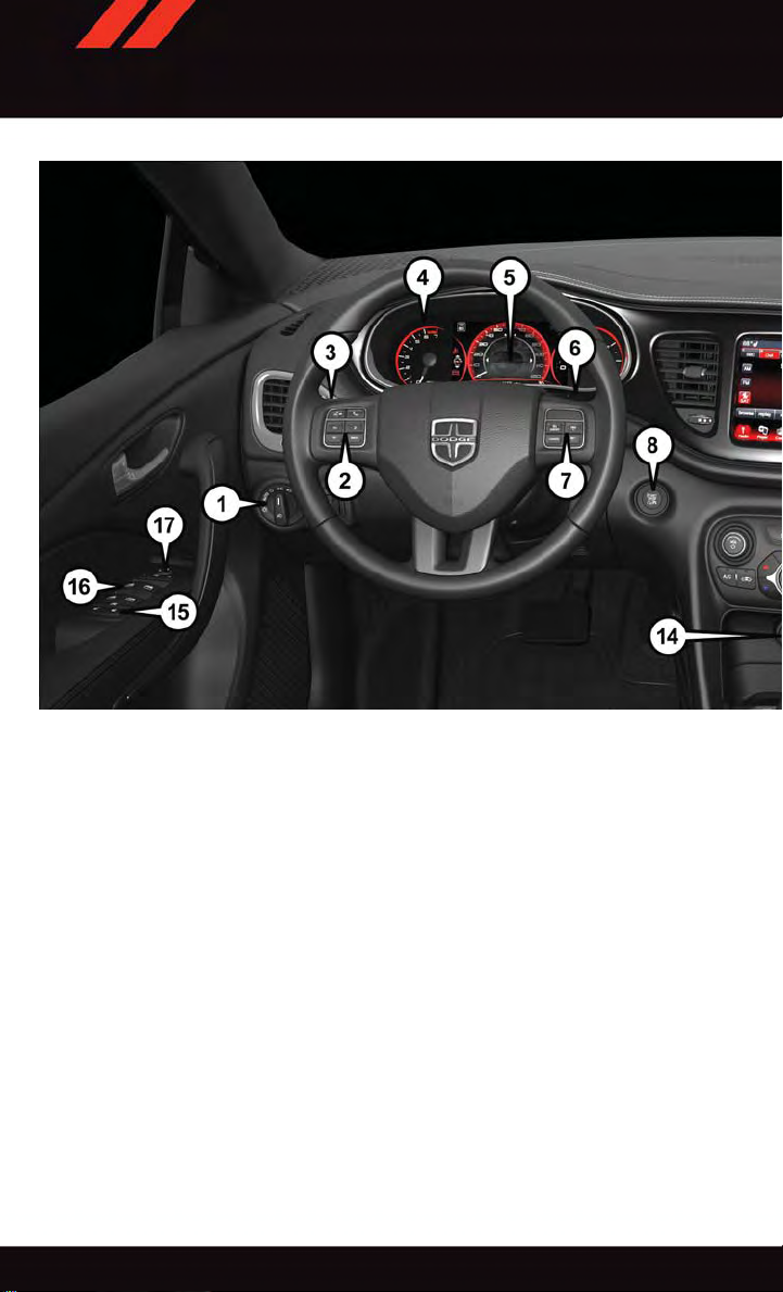
DRIVER COCKPIT
1. Headlight Switch pg. 36
2. Electronic Vehicle Information Center (EVIC) Control/Driver Information Display (DID)
pg. 6
3. T urn Signal/Wiper/Washer/High Beam Lever pg. 35
4. Instrument Cluster pg. 6
5. Electronic Vehicle Information Center (EVIC)/Driver Information Display (DID) pg. 6
6. Fuel Door Locator pg. 6
7. Speed Control pg. 37
8. Ignition Switch pg. 12
9. Audio System pg. 50
4
Page 7

CONTROLS AT A GLANCE
10. Switch Panel
•HazardSwitch
•ElectronicStabilityControl(ESC)OFFpg.99
11. Glove/Storage Compartment
12. Climate Control pg. 39
13. Shifter
14. Power Outlet pg. 96
15. Power Locks
16. Power Windows
17. Power Mirrors
5
Page 8
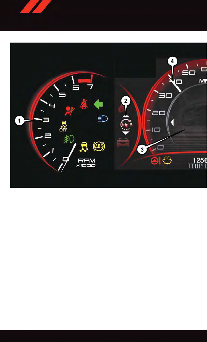
CONTROLS AT A GLANCE
INSTRUMENT CLUSTER
1. T achometer
2. Selectable Information Area — If Equipped
3. Electronic Vehicle Information Center (EVIC)/ Driver Information Display (DID)
4. Speedometer
(See page 99 for Instrument Cluster Warning Lights.)
6
Page 9
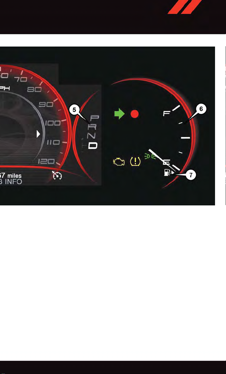
CONTROLS AT A GLANCE
5. Gear Position Display
6. Fuel Gauge
7. Fuel Door Location
(See page 105 for Instrument Cluster Indicator Lights.)
7
Page 10
GETTING STARTED
KEY FOB
Locking And Unlocking The Doors
Push and release the LOCK
the RKE transmitter to lock all doors. The
turn signal lights will flash, and the horn will
chirp to acknowledge the signal.
Push and release the UNLOCK
on the RKE transmitter once to unlock the
driver's door or twice within five seconds to
unlock all doors. The turn signal lights will
flash to acknowledge the unlock signal. The
illuminated entry system will also turn on.
1st Press Of Key Fob Unlocks
This feature lets you program the system to
unlock either the driver's door or all doors on
the first push of the UNLOCK button on the
RKE transmitter. To change the current setting, refer to your “Uconnect
“Understanding Your Instrument Panel” in
your Owner's Manual on the DVD for further
information.
button on
button
®
Settings” in
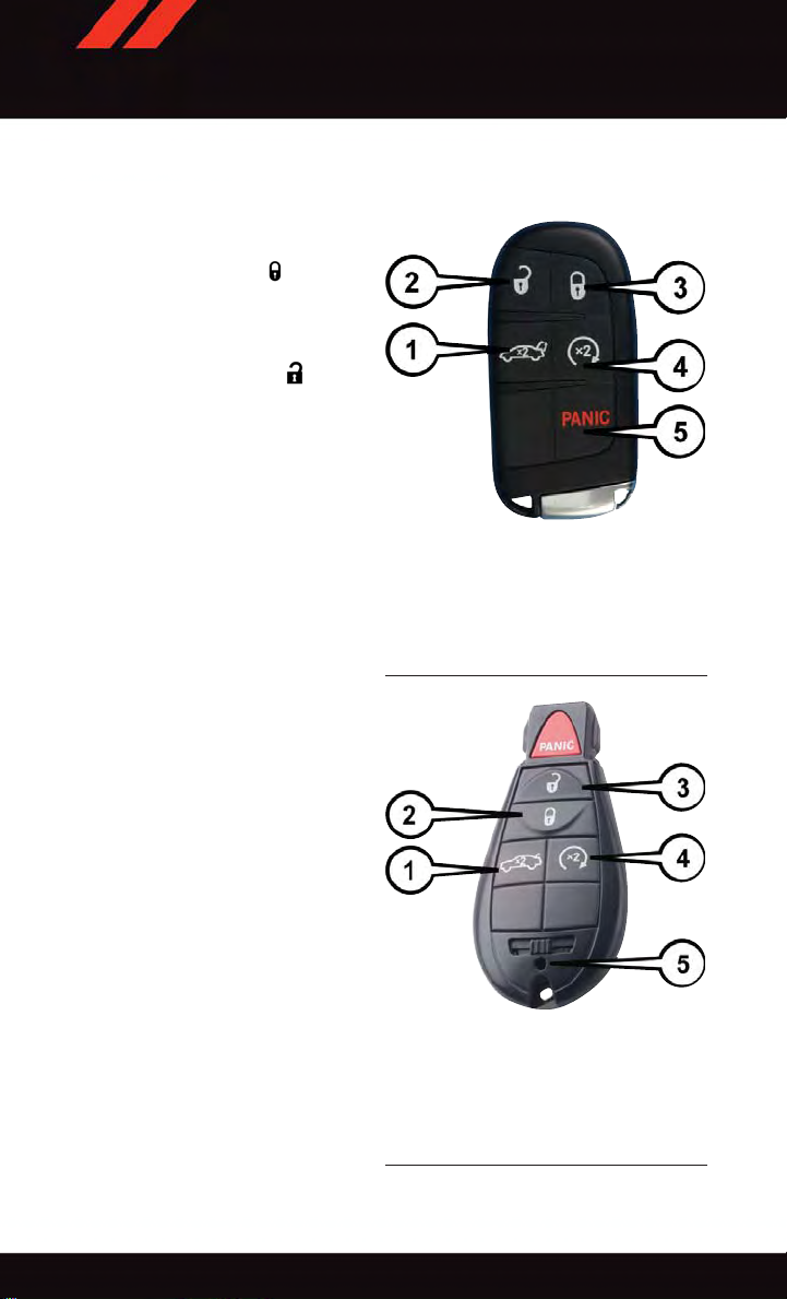
1—Decklid
2—Unlock
3—Lock
4—RemoteStart
5—Panic
Key Fob
Opening The Trunk
Push the T runk Release button on the transmitter two times within five seconds to open
the trunk.
Panic Alarm
1. Push the PANIC button once to turn the
panic alarm on.
2. Wait approximately three seconds and
push the button a second time to turn
the panic alarm off.
8
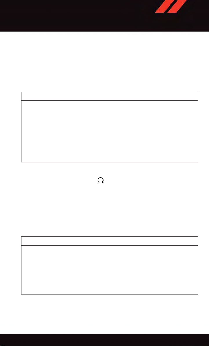
Key Fob
1—Decklid
2—Lock
3—Unlock
4—RemoteStart
5—EmergencyKey
Page 11
GETTING STARTED
Emergency Key
Should the battery in the vehicle or the Key Fob transmitter go dead, there is an
emergency key located in the Key Fob. To remove the emergency key, slide the button at
the back of the Key Fob sideways with your thumb and then pull the key out with your
other hand.
The emergency key is also used to lock the glove compartment.
WARNING!
•Neverleavechildrenaloneinavehicle,orwithaccesstoanunlockedvehicle.
Allowing children to be in a vehicle unattended is dangerous for a number of
reasons. A child or others could be seriously or fatally injured. Children should be
warned not to touch the parking brake, brake pedal or the transmission gear
selector.
•DonotleavetheKeyFobinornearthevehicle,orinalocationaccessibleto
children, and do not leave the ignition of a vehicle equipped with Keyless
Enter-N-Go™ in the ACC or ON/RUN mode. A child could operate power windows,
other controls, or move the vehicle.
REMOTE START
x
•PushtheREMOTESTARTbutton
•PushingtheREMOTESTARTbuttonathirdtimeshutstheengineoff.
•Todrivethevehicle,pushtheUNLOCKbuttonandcycletheignitiontotheON/RUN
position.
With remote start, the engine will only run for 15 minutes (timeout) unless the ignition is
cycled to the ON/RUN position.
The vehicle must be cycled to the ON/RUN position after two consecutive timeouts.
2
on the Key Fob twice within five seconds.
WARNING!
•Donotstartorrunanengineinaclosedgarageorconfinedarea.Exhaustgas
contains Carbon Monoxide (CO) which is odorless and colorless. Carbon Monoxide
is poisonous and can cause you or others to be severely injured or killed when
inhaled.
•KeepKeyFobtransmittersawayfromchildren.OperationoftheRemoteStart
System, windows, door locks or other controls could cause you and others to be
severely injured or killed.
9
Page 12
GETTING STARTED
KEYLESS ENTER-N-GO™
The Keyless Enter-N-Go™ system is an enhancement to the vehicle's Key Fob. This
feature allows you to lock and unlock the vehicle's door(s) and trunk without having to
push the Key Fob lock or unlock buttons, as well as starting and stopping the vehicle with
the push of a button.
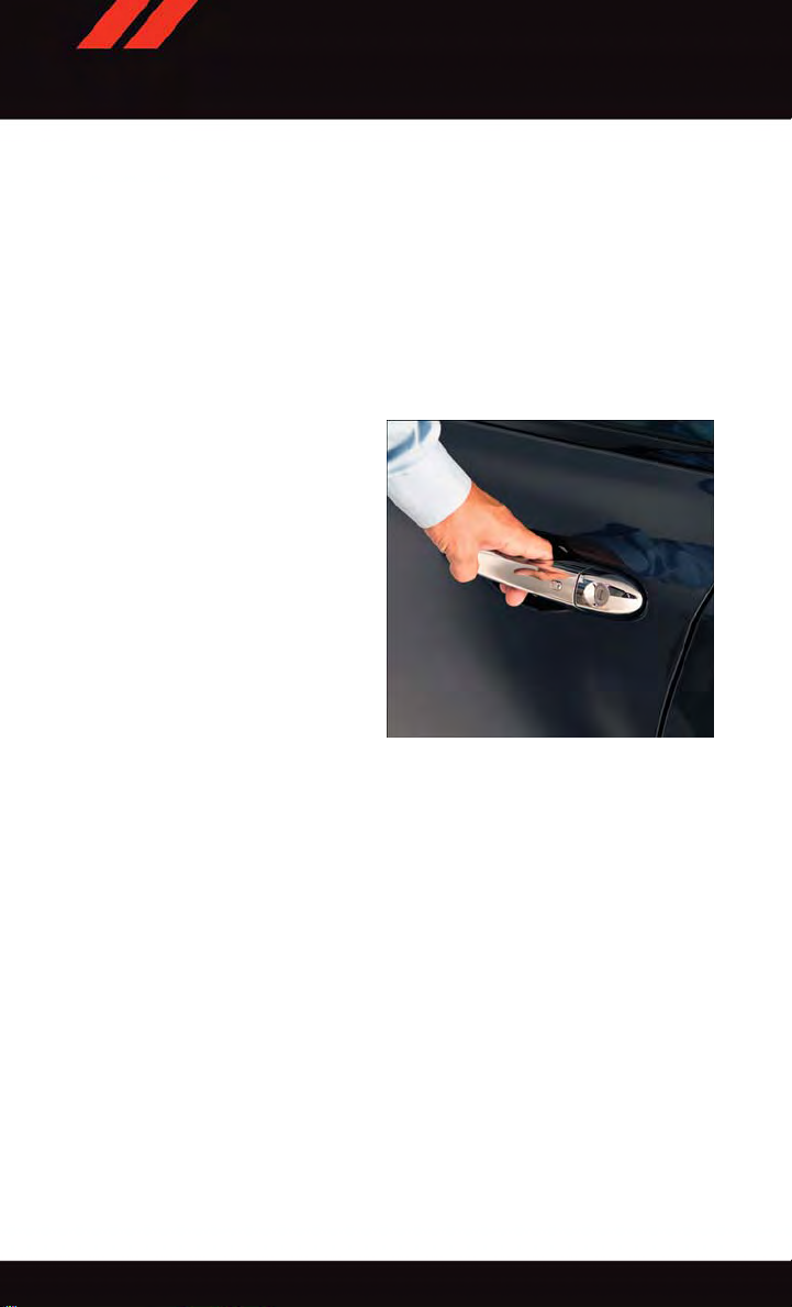
To Unlock From The Driver Or Passenger Side
With a valid Keyless Enter-N-Go™ Key Fob located outside the vehicle and within 5 ft
(1.5m) of the driver or passenger side door handle, grab either front door handle to unlock
the door automatically.
10
Grab The Door Handle To Unlock
Page 13
GETTING STARTED
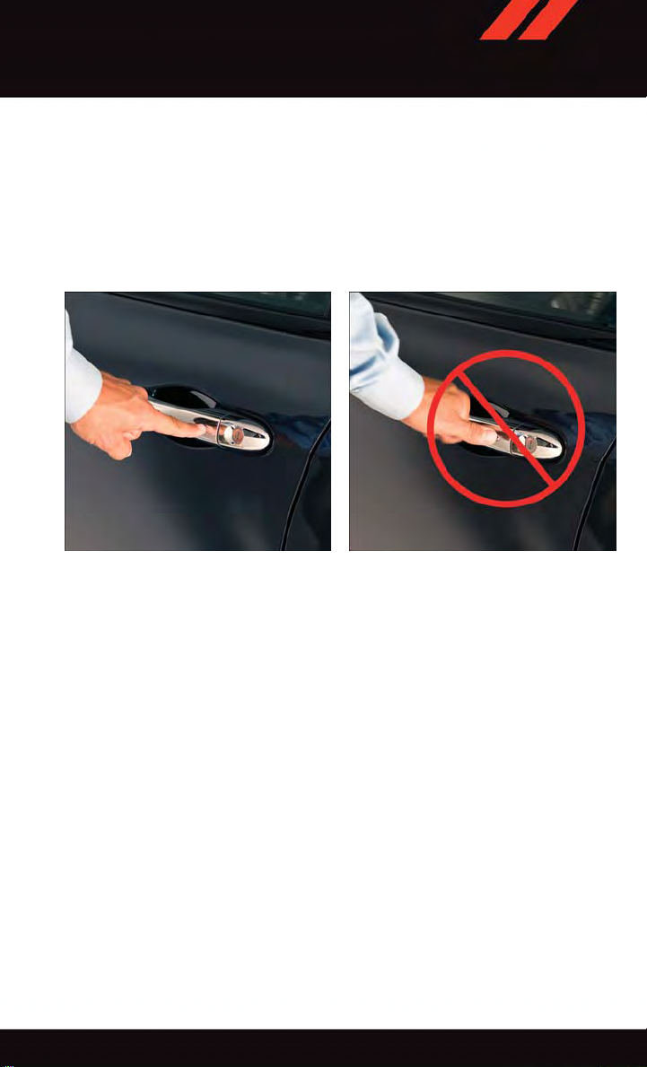
To Lock The Vehicle
Both front door handles have buttons located on the outside of the handle. With one of the
vehicle's Keyless Enter-N-Go™ Key Fobs located outside the vehicle and within 5 ft
(1.5 m) of the driver's or passenger front door handle, push the door handle button to lock
all four doors and trunk.
DO NOT grab the door handle when pushing the door handle button. This could unlock the
door(s).
Push The Door Handle To Lock Do NOT Grab The Handle When Locking
NOTE:
•If“UnlockAllDoors1stPress”isprogrammedalldoorswillunlockwhenyougrabhold
of the front driver's door handle. T o select between “Unlock Driver Door 1st Press” and
“Unlock All Doors 1st Press”, refer to the “Electronic Vehicle Information Center
(EVIC)” or “Driver Information Display (DID)” in your vehicle's Owner's Manual on the
DVD or “Programmable Features” in this guide for further information.
•If“UnlockAllDoors1stPress”isprogrammedalldoorsandtrunkwillunlockwhenyou
push the trunk button. If “Unlock Driver Door 1st Press” is programmed only the trunk
will unlock when you push the trunk button. T o select between “Unlock Driver Door 1st
Press” and “Unlock All Doors 1st Press”, refer to the “Electronic Vehicle Information
Center (EVIC)” or “Driver Information Display (DID)” in your vehicle's Owner's Manual
on the DVD or “Programmable Features” in this guide for further information.
•IfaKeyFobisdetectedinthevehiclewhenlockingthevehicleusingthepowerdoor
lock switch, the doors and trunk will unlock and the horn will chirp three times. On the
third attempt, your Key Fob can be locked inside the vehicle.
•AfterpushingtheKeylessEnter-N-Go™LOCKbutton,youmustwaittwoseconds
before you can lock or unlock the vehicle using the door handle. This is done to allow
you to check if the vehicle is locked by pulling the door handle, without the vehicle
reacting and unlocking.
11
Page 14

GETTING STARTED
•IfaKeylessEnter-N-Go™doorhandlehasnotbeenusedfor72hours,theKeyless
Enter-N-Go™ feature for that handle may time out. Pulling the deactivated front door
handle will reactivate the door handle's Keyless Enter-N-Go™ feature.
To Enter The Trunk
With a valid Keyless Enter-N-Go™ Key Fob
located outside the vehicle and within 5ft
(1.5 m) of the deck lid, push the button on
the right side of the light bar which is
located on the deck lid above the license
plate.
NOTE:
Refer to your Owner's Manual on the DVD
for further information.
Trunk Unlock Button
Engine Starting/Stopping
Starting
1. With a valid Keyless Enter-N-Go™ Key
Fob inside the vehicle.
2. Place the shift lever in PARK or NEU-
TRAL.
3. While pushing the brake pedal, push the
ENGINE ST AR T/STOP button once. If
the engine fails to start, the starter will
disengage automatically after 10 seconds.
4. T o stop the cranking of the engine prior
to the engine starting, push the button
again.
NOTE:
In case the ignition switch does not change with the push of a button, the RKE transmitter
(Key Fob) may have a low or dead battery . In this situation a back up method can be used
to operate the ignition switch. Put the nose side of the Key Fob against the ENGINE
STAR T/STOP button and push to operate the ignition switch.
Engine START/STOP Button
12
Page 15

GETTING STARTED
Stopping
1. Bring the vehicle to a complete stop.
2. Shift the transmission to PARK (P).
3. Push the ENGINE ST AR T/STOP button once. The ignition switch will return to the OFF
position.
NOTE:
If the transmission is not in PARK and the vehicle is in motion, the ENGINE START/STOP
button must be held for two seconds with the vehicle speed above 5 mph (8 km/h) before
the engine will shut off.
Accessory Positions With Engine Off
NOTE:
The following functions are with the driver’s foot OFF the brake pedal (transmission in
PARK o r NEUTRAL p osition ).
Starting With The Ignition Switch In The OFF Position:
•PushtheENGINESTART/STOPbuttononcetochangetheignitionswitchtotheACC
position.
•PushtheENGINESTART/STOPbuttonasecondtimetochangetheignitionswitchto
the ON/RUN position.
•PushtheENGINESTART/STOPbuttonathirdtimetoreturntheignitionswitchtothe
OFF position.
NOTE:
If the ignition switch is left in the ACC or
ON/RUN (engine not running) position and
the transmission is in PARK, the system will
automatically time out after 30 minutes of
inactivity and the ignition will switch to the
OFF position.
Ignition Positions
13
Page 16

GETTING STARTED
VEHICLE SECURITY ALARM
The Vehicle Security Alarm monitors the vehicle doors for unauthorized entry and the
Keyless Enter-N-Go™ START/STOP button for unauthorized operation. While the Vehicle
Security Alarm is armed, interior switches for door locks and decklid release are disabled.
If something triggers the alarm, the Vehicle Security Alarm will provide the following
audible and visible signals: the horn will pulse, the park lamps and/or turn signals will
flash, and the Vehicle Security Light in the instrument cluster will flash.
To Arm The System
Vehicles Not Equipped With Keyless Enter-N-Go™
Remove the key from the ignition switch and either push a power door LOCK switch while
the driver or passenger door is open or push the LOCK button on the Remote Keyless Entry
(RKE) transmitter. After the last door is closed, or if all doors are closed, the Vehicle
Security Alarm will arm itself in about 16 seconds. During that time, the Vehicle Security
Light will flash. If it does not illuminate, the Vehicle Security Alarm is not arming. In
addition, if you open a door during the arming period, the Vehicle Security Alarm will
cancel the arming process. If you wish to rearm the Vehicle Security Alarm after closing
the door, you must repeat one of the previously-described arming sequences.
You may also di sarm th e u ltrason ic intr usion sens or duri ng the 16 se cond ar ming pe riod
by pushing the lock button three times with a delay of no more than five seconds between
key pushes. The horn will pulse twice to acknowledge that the ultrasonic intrusion sensor
has been disabled.
NOTE:
•Thedriver’sdoorkeycylinderandthetrunkbuttonontheRKEtransmittercannotarm
or disarm the Vehicle Security Alarm.
•TheVehicleSecurityAlarmremainsarmedduringtrunkentry.PushingtheTRUNK
button will not disarm the Vehicle Security Alarm. If someone enters the vehicle
through the trunk, and opens any door, the alarm will sound.
•WhentheVehicleSecurityAlarmisarmed,theinteriorpowerdoorlockswitcheswill
not unlock the doors.
•Theultrasonicintrusionsensormaybeinadvertentlyactivatedbyachild,petorshifting
package left within the vehicle after the Vehicle Security Alarm is armed.
Vehicles Equipped With Keyless Enter-N-Go™
Push the Keyless Enter-N-Go™ START/STOP button until the EVIC/DID indicates that the
vehicle ignition is “OFF” (refer to “Starting Procedures” in “Starting And Operating” in
your Owner's Manual on the DVD for further information). Then either push the power door
LOCK switch while the driver or passenger door is open, push the Remote Keyless Entry
(RKE) transmitter LOCK button or push the Passive Entry Door Handle LOCK button (refer
to “Keyless Enter-N-Go™” in “Things To Know Before Starting Your Vehicle” in your
Owner's Manual on the DVD for further information).
14
Page 17

GETTING STARTED
To Disarm The System
The Vehicle Security Alarm is designed to protect your vehicle; however, you can create
conditions where the Vehicle Security Alarm will give you a false alarm. If one of the
previously-described arming sequences has occurred, the Vehicle Security Alarm will arm
regardless of whether you are in the vehicle or not. If you remain in the vehicle and open
adoor,thealarmwillsound.Ifthisoccurs,disarmtheVehicleSecurityAlarm.
If the Vehicle Security Alarm is armed and the battery becomes disconnected the Vehicle
Security Alarm will remain armed when the battery is reconnected. The exterior lights will
flash, and the horn will sound. If this occurs, disarm the Vehicle Security Alarm.
Vehicles Not Equipped With Keyless Enter-N-Go™
Either push the UNLOCK button on the RKE transmitter or insert a valid ignition key into
the ignition switch and turn the key to the ON/RUN position.
NOTE:
•Thedriver'sdoorkeycylinderandthetrunkbuttonontheRKEtransmittercannotarm
or disarm the Vehicle Security Alarm.
•TheVehicleSecurityAlarmremainsarmedduringtrunkentry.PushingtheTRUNK
button will not disarm the Vehicle Security Alarm. If someone enters the vehicle
through the trunk, and opens any door, the alarm will sound.
•WhentheVehicleSecurityAlarmisarmed,theinteriorpowerdoorlockswitcheswill
not unlock the doors.
Vehicles Equipped With Keyless Enter-N-Go™
Either push the UNLOCK button on the RKE transmitter or grasp the Passive Entry Unlock
Door Handle (refer to “Keyless Enter-N-Go™” in “Things To Know Before Starting Your
Vehicle” in your Owner's Manual on the DVD for further information), push the Keyless
Enter-N-Go™ ST ART/STOP button (requires at least one valid Key Fob in the vehicle), or
insert a valid Key Fob into the ignition switch (if the START/STOP button is removed) and
rotate it to the ON/RUN position.
Tamper Alert
If something has triggered the Vehicle Security Alarm in your absence, the horn will sound
three times and the exterior lights will blink three times when you disarm the V ehicle
Security Alarm. Check the vehicle for tampering.
15
Page 18

GETTING STARTED
SEAT BELT SYSTEMS
Lap/Shoulder Belts
•Allseatingpositionsinyourvehicleareequippedwithlap/shoulderbelts.
•Besureeveryoneinyourvehicleisinaseatandusingaseatbeltproperly.
•Positionthelapbeltsothatitissnugandlieslowacrossyourhips,belowyour
abdomen. To remove slack in the lap belt portion, pull up on the shoulder belt. To loosen
the lap belt if it is too tight, tilt the latch plate and pull on the lap belt. A snug seat belt
reduces the risk of sliding under the seat belt in a collision.
•Positiontheshoulderbeltacrosstheshoulderandchestwithminimal,ifanyslackso
that it is comfortable and not resting on your neck. The retractor will withdraw any slack
in the shoulder belt.
Seat Belt Pretensioner
•Thefrontseatbeltsystemisequippedwithpretensioningdevicesthataredesignedto
remove slack from the seat belt in the event of a collision.
•Adeployedpretensioneroradeployedairbagmustbereplacedimmediately.
WARNING!
•Inacollision,youandyourpassengerscansuffermuchgreaterinjuriesifyouare
not properly buckled up. Y ou can strike the interior of your vehicle or other
passengers, or you can be thrown out of the vehicle. Always be sure you and others
in your vehicle are buckled up properly.
•Ashoulderbeltplacedbehindyouwillnotprotectyoufrominjuryduringacollision.
You are more l ikely to h it your head in a c ollisio n if you do not we ar your should er
belt. The lap and shoulder belt are meant to be used together.
•Aseatbeltthatistooloosewillnotprotectyouproperly.Inasuddenstop,youcould
move too far forward, increasing the possibility of injury. Wear your seat belt snugly.
•Afrayedortornseatbeltcouldripapartinacollisionandleaveyouwithno
protection. Inspect the seat belt system periodically, checking for cuts, frays, or
loose parts. Damaged parts must be replaced immediately. Do not disassemble or
modify the system. Seat belt assemblies must be replaced after a collision.
16
Page 19

GETTING STARTED
SUPPLEMENTAL RESTRAINT SYSTEM (SRS) — AIR BAGS
Air Bag System Components
Your v ehicle ma y be equipp ed with the fo llowing a ir bag syst em compon ents:
•OccupantRestraintController(ORC)
•AirBagWarningLight
•SteeringWheelandColumn
•InstrumentPanel
•KneeImpactBolsters
•AdvancedFrontAirBags
•SupplementalSideAirBags
•SupplementalKneeAirBags
•FrontandSideImpactSensors
•SeatBeltPretenioners
•SeatBeltBuckleSwitch
•SeatTrackPositionSensors
•OccupantClassificationSystem
Advanced Front Air Bags
•ThisvehiclehasAdvancedFrontAirBagsforboththedriverandfrontpassengerasa
supplement to the seat belt restraint systems. The Advanced Front Air Bags will not
deploy in every type of collision.
•AdvancedFrontAirBagsaredesignedtoprovideadditionalprotectionbysupplementing the seat belts. Advanced Front Air Bags are not expected to reduce the risk of injury
in rear, side, or rollover collisions.
•TheAdvancedFrontAirBagswillnotdeployinallfrontalcollisions,includingsome
that may produce substantial vehicle damage — for example, some pole collisions,
truck underrides, and angle offset collisions.
•Ontheotherhand,dependingonthetypeandlocationofimpact,AdvancedFrontAir
Bags may deploy in crashes with little vehicle front-end damage but that produce a
severe initial deceleration.
•Becauseairbagsensorsmeasurevehicledecelerationovertime,vehiclespeedand
damage by themselves are not good indicators of whether or not an air bag should have
deployed.
•Seatbeltsarenecessaryforyourprotectioninallcollisions,andalsoareneededtohelp
keep you in position, away from an inflating air bag.
•Theairbagsmustbereadytoinflateforyourprotectioninacollision.TheOccupant
Restraint Controller (ORC) monitors the internal circuits and interconnecting wiring
associated with air bag system electrical components.
17
Page 20

GETTING STARTED
•TheORCturnsontheAirBagWarningLightintheinstrumentpanelforapproximately
four to eight seconds for a self-check when the ignition switch is first turned to the
ON/RUN position. After the self-check, the Air Bag Warning Light will turn off. If the
ORC detects a malfunction in any part of the system, it turns on the Air Bag Warning
Light, either momentarily or continuously. A single chime will sound to alert you if the
light comes on again after initial startup.
•TheORCmonitorsthereadinessoftheelectronicpartsoftheairbagsystemwhenever
the ignition switch is in the START or ON/RUN position. If the ignition switch is in the
OFF position or in the ACC position, the air bag system is not on and the air bags will
not inflate.
•IftheAirBagWarningLightintheinstrumentpanelisnotonduringthefourtoeight
seconds when the ignition switch is first turned to the ON/RUN position, stays on, or
turns on while driving, have the vehicle serviced by an authorized service center
immediately.
NOTE:
If the speedometer, tachometer, or any engine related gauges are not working, the
Occupant Restraint Controller (ORC) may also be disabled. In this condition the air bags
may not be ready to inflate for your protection. Have an authorized dealer service the air
bag system immediately.
•Afteranycollision,thevehicleshouldbetakentoanauthorizeddealerimmediately.
•Donotdriveyourvehicleaftertheairbagshavedeployed.Ifyouareinvolvedinanother
collision, the air bags will not be in place to protect you.
•Ifitisnecessarytomodifytheairbagsystemforpersonswithdisabilities,contactyour
authorized dealer.
•Referto“SupplementalRestraintSystem(SRS)”in“ThingsToKnowBeforeStarting
Your Vehi cle” in the Owne r's M anual on the DVD fo r further i nformat ion.
Occupant Classification System
This vehicle is equipped with a right front passenger Occupant Classification System
(“OCS”) that is designed to provide Passenger Advanced Front Air Bag output appropriate
to the occupant’s seated weight input, as determined by the OCS.
The Occupant Classification System (OCS) consists of the following:
•OccupantRestraintController(ORC)
•OccupantClassificationModule(OCM)andSensorlocatedinthefrontpassengerseat
•AirBagWarningLight
The OCS will NOT prevent deployment of the Passenger Advanced Front Air Bag. The OCS
may reduce the inflation rate of the Passenger Advanced Front Air Bag if the OCS
estimates that:
•Thefrontpassengerseatisunoccupiedorhasverylightobjectsonit;or
•Thefrontpassengerseatisoccupiedbyasmallpassenger,includingachild;or
18
Page 21

GETTING STARTED
•Thefrontpassengerseatisoccupiedbyarear-facingchildrestraint;or
•Thefrontpassengerisnotproperlyseatedorhisorherweightistakenoffoftheseat
for a period of time.
Front Passenger Seat Occupant Status Front Passenger Air Bag Output
Rear-facing child restraint Reduced-power deployment
Child, including a child in a forward-facing
child restraint or booster seat*
Properly seated adult
Unoccupied seat Reduced-power deployment
*Itispossibleforachildtobeclassifiedasanadult,allowingafull-powerPassenger
Advanced Front Air Bag deployment. Never allow children to ride in the front passenger
seat and never install a child restraint system, including a rear-facing child restraint, in the
front passenger seat.
The OCS determines the front passenger’s most probable classification.
The OCS estimates the seated weight on the front passenger seat and where that weight
is located. The OCS communicates the classification status to the ORC. The ORC uses the
classification to determine whether the Passenger Advanced Front Air Bag inflation rate
should be adjusted. In order for the OCS to operate as designed, it is important for the
front passenger to be seated properly and properly wearing the seat belt. Properly seated
passengers are:
•Sittingupright
•Facingforward
•Sittinginthecenteroftheseatwiththeirfeetcomfortablyonornearthefloor
•Sittingwiththeirbackagainsttheseatbackandtheseatbackinanuprightposition
Full-power deployment OR reducedpower deployment
Full-power deployment OR reducedpower deployment
Seated Properly
Lighter Weight Passengers (Including Small Adults)
When a lighter weight passenger, including a small adult, occupies the front passenger
seat, the OCS may reduce the inflation rate of the Passenger Advanced Front Air Bag. This
does not mean that the OCS is working improperly.
19
Page 22

GETTING STARTED
Do not decrease OR increase the front passenger’s seated weight on the front passenger
seat
The front passenger’s seated weight must be properly positioned on the front passenger
seat. Failure to do so may result in serious injury or death. The OCS determines the most
probable classification of the occupant that it detects. The OCS will detect the front
passenger’s decreased or increased seated weight, which may result in an adjusted
inflation rate of the Passenger Advanced Front Air Bag in a collision. This does not mean
that the OCS is working improperly. Decreasing the front passenger’s seated weight on the
front passenger seat may result in a reduced-power deployment of the Passenger
Advanced Front Air Bag. Increasing the front passenger’s seated weight on the front
passenger seat may result in a full-power deployment of the Passenger Advanced Front Air
Bag. Examples of improper front passenger seating include:
•Thefrontpassenger’sweightistransferredtoanotherpartofthevehicle(likethedoor,
arm rest or instrument panel).
•Thefrontpassengerleansforward,sideways,orturnstofacetherearofthevehicle.
•Thefrontpassenger’sseatbackisnotinthefulluprightposition.
•Thefrontpassengercarriesorholdsanobjectwhileseated(e.g.,backpack,box,etc.).
•Objectsarelodgedunderthefrontpassengerseat.
•Objectsarelodgedbetweenthefrontpassengerseatandcenterconsole.
•Accessoriesthatmaychangetheseatedweightonthefrontpassengerseatare
attached to the front passenger seat.
•Anythingthatmaydecreaseorincreasethefrontpassenger’sseatedweight.
The OCS determines the front passenger’s most probable classification. If an occupant in
the front passenger seat is seated improperly , the occupant may provide an output signal
to the OCS that is different from the occupant’s properly seated weight input, for example:
20
Not Seated Properly
Page 23

GETTING STARTED
The Air Bag Warning Light will turn on
whenever the OCS is unable to classify the
front passenger seat status. A malfunction
in the OCS may affect the operation of the
air bag system.
If the Air Bag Warning Light
come on, or stays on after you start the
vehicle, or it comes on as you drive, take the
vehicle to an authorized dealer for service
immediately.
The passenger seat assembly contains critical components that may affect the Passenger Advanced Front Air Bag inflation. In
order for the OCS to properly classify the
seated weight of a front seat passenger , the
OCS components must function as designed.
Do not make any modifications to the front
passenger seat components, assembly, or
to the seat cover. If the seat, trim cover, or
cushion needs service for any reason, take
the vehicle to your authorized dealer. Only
FCA US LLC approved seat accessories may
be used.
The following requirements must be strictly
followed:
•Donotmodifythefrontpassengerseat
assembly or components in any way.
•Donotusepriororfuturemodelyearseat
covers or cushions not designated by
FCA US LLC for the specific model being
repaired. Always use the correct seat
cover and cushion specified for the vehicle.
•Donotreplacetheseatcoverorcushion
with an aftermarket seat cover or cushion.
•Donotaddasecondaryseatcoveror
mat.
does not
Not Seated Properly
Not Seated Properly
Not Seated Properly
21
Page 24

GETTING STARTED
•AtnotimeshouldanySupplementalRestraintSystem(SRS)componentorSRS
related component or fastener be modified or replaced with any part except those which
are approved by FCA US LLC.
Supplemental Knee Air Bags
This vehicle is equipped with a Supplemental Driver Knee Air Bag mounted in the
instrument panel below the steering column and a Supplemental Passenger Knee Air Bag
mounted in the instrument panel below the glove compartment. The Supplemental Knee
Air Bags provide enhanced protection during a frontal impact by working together with the
seat belts, pretensioners, and Advanced Front Air Bags.
WARNING!
•Relyingontheairbagsalonecouldleadtomoresevereinjuriesinacollision.The
air bags work with your seat belt to restrain you properly. In some collisions, the air
bags won't deploy at all. Always wear your seat belts even though you have air bags.
•BeingtooclosetothesteeringwheelorinstrumentpanelduringAdvancedFrontAir
Bag deployment could cause serious injury, including death. Air bags need room to
inflate. Sit back, comfortably extending your arms to reach the steering wheel or
instrument panel.
•Noobjectsshouldbeplacedoverorneartheairbagontheinstrumentpanelor
steering wheel because any such objects could cause harm if the vehicle is in a
collision severe enough to cause the air bag to inflate.
Supplemental Side Air Bags
•ThisvehicleisequippedwithSupplementalSeat-MountedSideAirBags(SABs)
located in the outboard side of the front and rear (in vehicles equipped with outboard
rear seat SABs) seats. The SABs are marked with a SRS AIRBAG label sewn into the
outboard side of the seats.
•ThisvehicleisequippedwithSupplementalSideAirBagInflatableCurtains(SABICs)
located above the side windows. The trim covering the SABICs is labeled SRS AIRBAG.
The SABICs may help reduce the risk of partial or complete ejection of vehicle
occupants through side windows in certain side impact events.
•TheSABICsandSABs(“SideAirBags”)aredesignedtoactivateincertainside
impacts. The Occupant Restraint Controller (“ORC”) determines whether the deployment of the Side Air Bags in a particular impact event is appropriate, based on the
severity and type of collision. Vehicle damage by itself is not a good indicator of whether
or not Side Air Bags should have deployed.
22
Page 25

GETTING STARTED
WARNING!
•SideAirBagsneedroomtoinflate.Donotleanagainstthedoororwindow.Sit
upright in the center of the seat.
•BeingtooclosetotheSideAirBagsduringdeploymentcouldcauseyoutobe
severely injured or killed.
•RelyingontheSideAirBagsalonecouldleadtomoresevereinjuriesinacollision.
The Side Air Bags work with your seat belt to restrain you properly. In some
collisions, Side Air Bags won’t deploy at all. Always wear your seat belt even though
you have Side Air Bags.
•ThisvehicleisequippedwithleftandrightSupplementalSideAirBagInflatable
Curtains (SABICs). Do not stack luggage or other cargo up high enough to block the
deployment of the SABICs. The trim covering above the side windows where the
SABIC and its deployment path are located should remain free from any obstructions.
•ThisvehicleisequippedwithSABICs.InorderfortheSABICstoworkasintended,
do not install any accessory items in your vehicle which could alter the roof. Do not
add an aftermarket sunroof to your vehicle. Do not add roof racks that require
permanent attachments (bolts or screws) for installation on the vehicle roof. Do not
drill into the roof of the vehicle for any reason.
•DonotuseaccessoryseatcoversorplaceobjectsbetweenyouandtheSideAir
Bags; the performance could be adversely affected and/or objects could be pushed
into you, causing serious injury.
CHILD RESTRAINTS
Children 12 years or younger should ride properly buckled up in a rear seat, if available.
According to crash statistics, children are safer when properly restrained in the rear seats
rather than in the front.
Every state in the United States and all Canadian provinces require that small children
ride in proper restraint systems. This is the law, and you can be prosecuted for ignoring it.
NOTE:
•Foradditionalinformation,refertowww.Seatcheck.orgorcall1-866-SEATCHECK.
•CanadianresidentsshouldrefertoTransportCanada’swebsiteforadditionalinformation: http://www.tc.gc.ca/eng/motorvehiclesafety/safedrivers-childsafety-index-53.htm
23
Page 26

GETTING STARTED
LATCH – Lower Anchors And Tethers For CHildren
Your vehicle is equipp ed w ith the child
restraint anchorage system called LATCH,
which stands for Lower Anchors and T ethers
for CHildren.
The rear outboard seating positions have
lower anchors and top tether anchors. The
rear center seating position has a top tether
anchor only.
LATCH Weight Limit
You m ay use the LATCH anch or age s ystem
until the combined weight of the child and
the child restraint is 65 lbs (29.5 kg). Use
the seat belt and tether anchor instead of
the LATCH system once the combined
weight is more than 65 lbs (29.5 kg).
Locating LATCH Anchorages
The lower anchorages are round bars that are found at the rear of the seat cushion
where it meets the seatback, below the anchorage symbols on the seatback. They are just
visible when you lean into the rear seat to install the child restraint. You will easily feel
them if you run your finger along the gap between the seatback and seat cushion.
Lower Anchors
Locating Tether Anchorages
In addition, there are tether strap anchorages behind each rear seating position
located in the panel between the rear seatback and the rear window. These tether
strap anchorages are under a plastic cover
with the tether anchorage symbol on it.
Center Seat LATCH
Do not install child restraints with rigid
lower attachments in the center seating
position. Only install this type of child restraint in the outboard seating positions.
Child restraints with flexible, webbing
mounted lower attachments can be installed in any rear seating position. In the
center position, the inner anchorages are
17 inches (440 mm) apart.
24
Tether Anchorages
Page 27

GETTING STARTED
Installing The Child Restraint Using The LATCH Lower Anchors
NOTE:
Never “share” a LA TCH anchorage with two or more child restraints.
1. Loosen the adjusters on the lower straps and on the tether strap of the child seat so that
you can more easily attach the hooks or connectors to the vehicle anchorages.
2. Attach the lower hooks or connectors of the child restraint to the lower anchorages in
the selected seating position.
3. If the child restraint has a tether strap, connect it to the top tether anchorage. See
below for directions to attach a tether anchor.
4. T ighten all of the straps as you push the child restraint rearward and downward into the
seat. Remove slack in the straps according to the child restraint manufacturer’ s
instructions.
5. T est that the child restraint is installed tightly by pulling back and forth on the child
seat at the belt path. It should not move more than 1 inch (25.4 mm) in any direction.
Installing The Child Restraint Using The Vehicle Seat Belts
The seat belts in the passenger seating positions are equipped with a Switchable
Automatic Locking Retractor (ALR) that is designed to keep the lap portion of the seat belt
tight around the child restraint. Any seat belt system will loosen with time, so check the
belt occasionally, and pull it tight if necessary.
Tether Anchorage Weight Limit
Always use the tether anchor when using the seat belt to install a forward facing child
restraint, up to the recommended weight limit of the child restraint.
To Install A Child Seat Using An ALR:
1. Pull enough of the seat belt webbing from the retractor to pass it through the belt path
of the child restraint. Do not twist the belt webbing in the belt path.
2. Slide the latch plate into the buckle until you hear a “click.”
3. Pull on the webbing to make the lap portion tight against the child seat.
4. T o lock the seat belt, pull down on the shoulder part of the belt until you have pulled
all the seat belt webbing out of the retractor. Then, allow the webbing to retract back
into the retractor. As the webbing retracts, you will hear a clicking sound. This means
the seat belt is now in the Automatic Locking mode.
5. T ry to pull the webbing out of the retractor. If it is locked, you should not be able to pull
out any webbing. If the retractor is not locked, repeat the last step.
6. Finally , pull up on any extra webbing to tighten the lap portion around the child
restraint while you push the child restraint rearward and downward into the vehicle
seat.
25
Page 28

GETTING STARTED
7. If the child restraint has a top tether strap and the seating position has a top tether
anchorage, connect the tether strap to the anchorage and tighten the tether strap. See
below for directions to attach a tether anchor.
8. T est that the child restraint is installed tightly by pulling back and forth on the child
seat at the belt path. It should not move more than 1 inch (25.4 mm) in any direction.
Installing The Top Tether Strap (With Either Lower Anchors Or Vehicle Seat Belt):
When installing a forward-facing child restraint, always secure the top tether strap, up to
the tether anchor weight limit, whether the child restraint is installed with the lower
anchors or the vehicle seat belt.
Tether Strap Installation
1. Rotate or lift the cover to access the anchor directly behind the seat where you are
placing the child restraint.
2. Route the tether strap to provide the most direct path for the strap between the anchor
and the child seat.
3. If your vehicle is equipped with adjustable rear head restraints, raise the head
restraint, and where possible, route the tether strap under the head restraint and
between the two posts. If not possible, lower the head restraint and pass the tether
strap around the outboard side of the head restraint.
4. Attach the tether strap hook of the child restraint to the top tether anchorage and
remove slack in the tether strap according to the child restraint manufacturer’s
instructions.
26
Tether Strap Mounting
1—Cover
3—AttachingStrap
A—TetherStrapHook
B—TetherAnchor
Page 29

GETTING STARTED
WARNING!
•Inacollision,anunrestrainedchild,evenatinybaby,canbecomeaprojectile
inside the vehicle. The force required to hold even an infant on your lap could
become so great that you could not hold the child, no matter how strong you are.
The child and others could be severely injured or killed. Any child riding in your
vehicle should be in a proper restraint for the child's size.
•Rearward-facingchildseatsmustneverbeusedinthefrontseatofavehiclewith
afrontpassengerairbag.Anairbagdeploymentcouldcausesevereinjuryordeath
to infants in this position.
•Onlyusearearward-facingchildrestraintinavehiclewitharearseat.
•ImproperinstallationofachildrestrainttotheLATCHanchoragescanleadto
failure of an infant or child restraint. The child could be severely injured or killed.
Follow the manufacturer’s directions exactly when installing an infant or child
restraint.
•Anincorrectlyanchoredtetherstrapcouldleadtoincreasedheadmotionand
possible injury to the child. Use only the anchor positions directly behind the child
seat to secure a child restraint top tether strap.
•Ifyourvehicleisequippedwithasplitrearseat,makesurethetetherstrapdoesnot
slip into the opening between the seatbacks as you remove slack in the strap.
HEAD RESTRAINTS
Head restraints are designed to reduce the risk of injury by restricting head movement in
the event of a rear impact. Head restraints should be adjusted so that the top of the head
restraint is located above the top of your ear.
WARNING!
The head restraints for all occupants must be properly installed and adjusted prior to
operating the vehicle or occupying a seat. Head restraints should never be adjusted
while the vehicle is in motion. Driving a vehicle with the head restraints improperly
adjusted or removed could cause serious injury or death in the event of a collision.
Reactive Head Restraints — Front Seats
The front driver and passenger seats are equipped with Reactive Head Restraints (RHR).
In the event of a rear impact the RHRs will automatically extend forward minimizing the
gap between the back of the occupants head and the RHR.
The RHRs will automatically return to their normal position following a rear impact. If the
RHRs do not return to their normal position see your authorized dealer immediately.
27
Page 30

GETTING STARTED
To rai se t h e h e ad r est r ain t, p u ll u pwa r d on t h e hea d res tra i nt. To l owe r the h e ad r est r ain t,
push the adjustment button, located at the base of the head restraint, and push downward
on the head restraint.
NOTE:
To rem o ve t he h e ad r e str ain t , rai s e it a s f ar a s i t can g o t hen p ush t h e rel e ase b utto n and
the adjustment button at the base of each post while pulling the head restraint up.
Seatback angle may need to be adjusted to fully remove the head restraint. To reinstall the
head restraint, put the head restraint posts into the holes and push downward. Then
adjust the head restraint to the appropriate height.
WARNING!
•Alooseheadrestraintthrownforwardinacollisionorhardstopcouldcauseserious
injury or death to occupants of the vehicle. Always securely stow removed head
restraints in a location outside the occupant compartment.
•ALLtheheadrestraintsMUSTbereinstalledinthevehicletoproperlyprotectthe
occupants. Follow the re-installation instructions above prior to operating the
vehicle or occupying a seat.
•DonotplaceitemsoverthetopoftheReactiveHeadRestraint,suchascoats,seat
covers or portable DVD players. These items may interfere with the operation of the
Reactive Head Restraint in the event of a collision and could result in serious injury
or death.
Rear Head Restraints
The rear outboard head restraints have three positions UP, MID and DOWN. The center
head restraint has only two positions, UP and DOWN. When the center seat is being
occupied the head restraint should be in the raised position. When there are no occupants
in the center seat the head restraint can be lowered for maximum visibility for the driver.
To rai se t h e h e ad r est r ain t, p u ll u pwa r d on t h e hea d res tra i nt. To l owe r the h e ad r est r ain t,
push the adjustment button, located at the base of the head restraint, and push downward
on the head restraint.
NOTE:
To rem o ve t he h e ad r e str ain t , rai s e it a s f ar a s i t can g o t hen p ush t h e rel e ase b utto n and
the adjustment button at the base of each post while pulling the head restraint up.
Seatback needs to be folded forward to fully remove the head restraint. To reinstall the
head restraint, put the head restraint posts into the holes and push downward. Then
adjust the head restraint to the appropriate height.
28
Page 31

GETTING STARTED
WARNING!
•Alooseheadrestraintthrownforwardinacollisionorhardstopcouldcauseserious
injury or death to occupants of the vehicle. Always securely stow removed head
restraints in a location outside the occupant compartment.
•ALLtheheadrestraintsMUSTbereinstalledinthevehicletoproperlyprotectthe
occupants. Follow the re-installation instructions above prior to operating the
vehicle or occupying a seat.
•DonotplaceitemsoverthetopoftheReactiveHeadRestraint,suchascoats,seat
covers or portable DVD players. These items may interfere with the operation of the
Reactive Head Restraint in the event of a collision and could result in serious injury
or death.
FRONT SEATS
Power Seats
The power seat switch is located on the outboard side of the seat near the floor.
The power seat switch controls forward/
back, up/down and tilt adjustment.
The recline switch controls the angle of the
seatback. Push the switch forward or rearward and the seatback will move in either
direction.
Power Lumbar
Push the switch forward to increase the
lumbar support. Push the switch rearward
to decrease the lumbar support.
Pushing upward or downward on the switch
will raise and lower the position of the
support.
Power Seat Switches
1—PowerSeatSwitch
2—ReclineSwitch
3—PowerLumbarSwitch
29
Page 32

GETTING STARTED
Manual Seat Adjustment
Forward/Rearward
Lift up on the adjusting bar located at the
front of the seat near the floor and release at
the desired position. Then, using body pressure, move forward and backward on the
seat to be sure that the seat adjusters have
latched.
Recliner
Lean forward in the seat and lift the recliner
lever, then lean back to the desired position
and release the lever.
Lift the lever to return the seatback to an
upright position.
1—Forward/RearwardAdjustingBar
2—HeightAdjustment
3—ReclinerLever
Height Adjustment
Ratchet the front lever, located on the outboard side of the seat, upward to raise the seat
height.
Ratchet the lever downward to lower the seat height.
Manual Seat Adjustment
CAUTION!
Do not place any article under a power seat or impede its ability to move as it may cause
damage to the seat controls. Seat travel may become limited if movement is stopped
by an obstruction in the seat's path.
WARNING!
•Adjustingaseatwhilethevehicleismovingisdangerous.Thesuddenmovementof
the seat could cause you to lose control. The seat belt might not be properly
adjusted, and you could be severely injured or killed. Only adjust a seat while the
vehicle is parked.
•Donotridewiththeseatbackreclinedsothattheseatbeltisnolongerresting
against your chest. In a collision, you could slide under the seat belt and be severely
injured or killed. Use the recliner only when the vehicle is parked.
30
Page 33

GETTING STARTED
REAR SEAT
Folding Rear Seatback
Pull on the loops, located near the outer top
of the seatbacks, to fold down either or both
seatbacks. These loops can be tucked away
when not in use.
When the seatback is raised to the upright
position, make sure it is latched by strongly
pulling on the top of the seatback above the
seat loop.
Seatback Loops Locations
WARNING!
•Becertainthattheseatbackissecurelylockedintoposition.Iftheseatbackisnot
securely locked into position, the seat will not provide the proper stability for child
seats and/or passengers. An improperly latched seat could cause you and others to
severely injured or killed.
•Thecargoareaintherearofthevehicle(withtherearseatbacksinthelocked-upor
folded-down position) should not be used as a play area by children when the
vehicle is in motion. They could be severely injured or killed in a collision. Children
should be seated and using the proper restraint system.
31
Page 34

GETTING STARTED
HEATED SEATS
Front Heated Seats
The front heated seats control buttons are located within the Uconnect®system. You can
gain access to the control buttons through the climate screen or the controls screen.
•Presstheheatedseatbutton
•Presstheheatedseatbutton
•Presstheheatedseatbutton
If the HI-level setting is selected, the system will automatically switch to LO-level after
approximately 60 minutes. The LO-level setting will turn OFF automatically after approximately 45 minutes.
NOTE:
On models that are equipped with remote start, this feature can be programmed to come
on during a remote start through the Uconnect
in “Understanding Your Instrument Panel” in the Owner's Manual on the DVD.
•Personswhoareunabletofeelpaintotheskinbecauseofadvancedage,chronic
illness, diabetes, spinal cord injury, medication, alcohol use, exhaustion or other
physical conditions must exercise care when using the seat heater. It may cause
burns even at low temperatures, especially if used for long periods of time.
•Donotplaceanythingontheseatthatinsulatesagainstheat,suchasablanketor
cushion. This may cause the seat heater to overheat. Sitting in a seat that has been
overheated could cause serious burns due to the increased surface temperature of
the seat.
once to turn the HI setting On.
asecondtimetoturntheLOsettingOn.
athirdtimetoturntheheatingelementsOFF.
®
system. Refer to “Uconnect®Settings”
WARNING!
HEATED STEERING WHEEL
The steering wheel contains a heating element that heats the steering wheel to one
temperature setting.
The heated steering wheel control button is located within the Uconnect
gain access to the control buttons through the climate screen or the controls screen.
•Presstheheatedsteeringwheelbutton
•Presstheheatedsteeringwheelbutton
OFF.
Once the heated steering wheel has been turned on, it will operate for up to 80 minutes
before automatically shutting off. The heated steering wheel can shut off early or may not
turn on when the steering wheel is already warm.
once to turn the heating element ON.
asecondtimetoturntheheatingelement
32
®
system. You can
Page 35

GETTING STARTED
NOTE:
On models that are equipped with Remote Start, this feature can be programmed to come
on during a Remote Start through the Uconnect
in “Understanding Your Instrument Panel” in the Owner's Manual on the DVD.
WARNING!
•Personswhoareunabletofeelpaintotheskinbecauseofadvancedage,chronic
illness, diabetes, spinal cord injury, medication, alcohol use, exhaustion, or other
physical conditions must exercise care when using the steering wheel heater. It may
cause burns even at low temperatures, especially if used for long periods.
•Donotplaceanythingonthesteeringwheelthatinsulatesagainstheat,suchasa
blanket or steering wheel covers of any type and material. This may cause the
steering wheel heater to overheat.
TILT/TELESCOPING STEERING COLUMN
The tilt/telescoping control lever is located
below the steering wheel at the end of the
steering column.
1. Push down on the lever to unlock the
steering column.
2. T o tilt the steering column, move the
steering wheel upward or downward as
desired.
3. T o lengthen or shorten the steering column, pull the steering wheel outward or
push it inward as desired.
4. Pull upward on the lever to lock the
column firmly in place.
®
system. Refer to “Uconnect®Settings”
Tilt/Telescoping Control Lever
WARNING!
Do not adjust the steering wheel while driving. The tilt/telescoping adjustment must be
locked while driving. Adjusting the steering wheel while driving or driving without the
tilt/telescoping adjustment locked could cause the driver to lose control of the vehicle.
Failure to follow this warning may result in you and others being severely injured or
killed.
33
Page 36

OPERATING YOUR VEHICLE
ENGINE BREAK-IN RECOMMENDATIONS
Alongbreak-inperiodisnotrequiredfortheengineanddrivetrain(transmissionandaxle)
in your vehicle.
Drive moderately during the first 300 miles (500 km). After the initial 60 miles (100 km),
speeds up to 50 or 55 mph (80 or 90 km/h) are desirable.
While cruising, brief full-throttle acceleration within the limits of local traffic laws
contributes to a good break-in. Wide-open throttle acceleration in low gear can be
detrimental and should be avoided.
The engine oil installed in the engine at the factory is a high-quality energy conserving type
lubricant. Oil changes should be consistent with anticipated climate conditions under
which vehicle operations will occur. Refer to “Maintaining Your Vehicle”, for the recommended viscosity and quality grades.
NOTE:
Anewenginemayconsumesomeoilduringitsfirstfewthousandmiles(kilometers)of
operation. This should be considered a normal part of the break-in and not interpreted
as an indication of an engine problem or malfunction.
CAUTION!
Never use Non-Detergent Oil or Straight Mineral Oil in the engine or damage may
result.
34
Page 37

OPERATING YOUR VEHICLE
TURN SIGNAL/WIPER/WASHER/HIGH BEAM LEVER
Multifunction Lever
1—PushForWasher
2—RotateDownwardForMist
3—PushLeverForHighBeams
Turn Signal/Lane Change Assist
Tap t h e lev er u p o r dow n o nce a n d the t u rn s ign a l (ri g ht o r l eft ) wil l f las h t hre e time s and
automatically turn off.
Front Wipers
Intermittent, Low And High Operation
Rotate the end of the lever to the first detent position for one of four intermittent settings,
the second detent for low wiper operation and the third detent for high wiper operation.
Mist
Rotate the end of the lever rearward when a single wipe is desired.
NOTE:
The mist feature does not activate the washer pump; therefore, no washer fluid will be
sprayed on the windshield. The wash function must be activated in order to spray the
windshield with washer fluid.
Washer Operation
Push the end of the lever inward and hold for as long as spray is desired.
35
Page 38

OPERATING YOUR VEHICLE
Rain Sensing Wipers
This feature senses moisture on the vehicle's windshield and automatically activates the
wipers for the driver when the switch is in the intermittent position. Rotate the end of the
lever to one of four settings to activate this feature and adjust sensitivity.
Rain Sensing can be turned on and off using the Uconnect
Manual on the DVD for further details.
High Beam Operation
Push the lever forward to activate the high beams. Pull the lever toward you for flash to
pass.
NOTE:
For safe driving, turn off the high beams when oncoming traffic is present to prevent
headlight glare and as a courtesy to other motorists.
HEADLIGHT SWITCH
Automatic Headlights/Parking Lights/Headlights
Rotate the headlight switch, located on the
instrument panel to the left of the steering
wheel, to the first detent for parking lights
and to the second detent for head-
lights
With the parking lights or low beam headlights on, push the headlight switch once
for fog lights.
Rotate the headlight switch to AUTO for
AUTO headlights if equipped with this feature.
When set to AUTO, the system automatically turns the headlights on or off based on
ambient light levels.
Fog Lights — If Equipped
Turn t he h ead l igh ts o r par kin g lig h ts o n a n d
push the headlight switch once to turn the
fog lights on.
Push the switch a second time to turn the fog lights off. Fog lights will not operate when
high beams are on.
Afoglightsymbolwillilluminateintheclustertoindicatethefoglightsareon.
36
.
1—Auto-IfEquipped
2—RotateHeadlightSwitch
3—RotateDimmer
4—RotateAmbientLightControl-If
Equipped
®
System, refer to the Owner's
Headlight Switch Premium Model
Page 39

OPERATING YOUR VEHICLE
Instrument Panel Dimmer
•Rotatethedimmercontroltotheextremebottompositiontofullydimtheinstrument
panel lights and prevent the interior lights from illuminating when a door is opened.
•Rotatethedimmercontroluptoincreasethebrightnessoftheinstrumentpanelwhen
the parking lights or headlights are on.
•Rotatethedimmercontroluptothenextdetentpositiontofullybrightentheodometer
and radio when the parking lights or headlights are on.
•Rotatethedimmercontroluptothelastdetentpositiontoturnontheinteriorlighting.
If your vehicle is equipped with a touchscreen, the dimming is programmable through the
Uconnect
Panel” in the Owner's Manual on the DVD for further details.
ELECTRONIC SPEED CONTROL — IF EQUIPPED
The Electronic Speed Control switches are
located on the steering wheel.
Cruise ON/OFF
•PushtheON/OFFbuttontoactivatethe
NOTE:
CRUISE
cluster to indicate the Speed Control is on.
•PushtheON/OFFbuttonasecondtime
®
system. Refer to “Uconnect®Settings ” in “Understanding Your Instrument
Speed Control.
will appear on the instrument
to turn the system off.
SET
With the Speed Control on, push and release the SET – button to set a desired
speed.
Electronic Speed Control Switches
1—PushCANCEL
2—PushON/OFF
3—PushResume/Accel
4—PushSet/Decel
Accel/Decel
To Increase Speed
When the Electronic Speed Control is set, you can increase speed by pushing the RES +
button.
37
Page 40

OPERATING YOUR VEHICLE
The drivers preferred units can be selected through the instrument panel settings if
equipped. The speed increment shown is dependant on the chosen speed unit of U.S.
(MPH) or Metric (km/h):
U.S. Speed (MPH)
•PushingtheRES+ button once will result in a 1 MPH increase in set speed. Each
subsequent tap of the button results in an increase of 1 MPH.
•Ifthebuttoniscontinuallypushed,thesetspeedwillcontinuetoincreaseuntilthe
button is released, then the new set speed will be established.
Metric Speed (km/h)
•PushingtheRES+ button once will result in a 1 km/h increase in set speed. Each
subsequent tap of the button results in an increase of 1 km/h.
•Ifthebuttoniscontinuallypushed,thesetspeedwillcontinuetoincreaseuntilthe
button is released, then the new set speed will be established.
To Decrease Speed
When the Electronic Speed Control is set, you can decrease speed by pushing the SET button.
The drivers preferred units can be selected through the instrument panel settings if
equipped. The speed decrement shown is dependant on the chosen speed unit of U.S.
(MPH) or Metric (km/h):
U.S. Speed (MPH)
•PushingtheSET- button once will result in a 1 MPH decrease in set speed. Each
subsequent tap of the button results in a decrease of 1 MPH.
•Ifthebuttoniscontinuallypushed,thesetspeedwillcontinuetodecreaseuntilthe
button is released, then the new set speed will be established.
Metric Speed (km/h)
•PushingtheSET- button once will result in a 1 km/h decrease in set speed. Each
subsequent tap of the button results in a decrease of 1 km/h.
•Ifthebuttoniscontinuallypushed,thesetspeedwillcontinuetodecreaseuntilthe
button is released, then the new set speed will be established.
Resume
To r esu m e a pre v iou s ly sel e cte d s e t s pee d in mem o ry, p ush the R ES + b u tto n a n d r ele a se.
Cancel
Push the CANCEL button, or apply the brakes to cancel the set speed and maintain the set
speed memory.
Push the ON/OFF button to turn the system off and erase the set speed memory.
38
Page 41

OPERATING YOUR VEHICLE
WARNING!
•LeavingtheElectronicSpeedControlsystemonwhennotinuseisdangerous.You
could accidentally set the system or cause it to go faster than you want. You could
lose control and have a collision. Always leave the Electronic Speed Control system
off when you are not using it.
•ElectronicSpeedControlcanbedangerouswherethesystemcannotmaintaina
constant speed. Your vehicle could go too fast for the conditions, and you could lose
control. A collision could be the result. Do not use Electronic Speed Control in
heavy traffic or on roads that are winding, icy, snow-covered or slippery.
MANUAL CLIMATE CONTROLS
Manual Climate Controls
1—RotateBlowerControl
2—PushAirRecirculationButton
3—RotateTemperatureControl
4—PushA/CButton
5—RotateModeControl
6—PushRearDefrosterButton
Air Recirculation
Use Recirculation for maximum A/C operation.
For window defogging, turn the Recirculation button off.
Recirculation is allowed in floor and defrost/floor (mix modes) for approximately five
minutes.
Heated Mirrors — If Equipped
The mirrors are heated to melt frost or ice. This feature is activated whenever you turn on
the rear window defroster.
39
Page 42

OPERATING YOUR VEHICLE
Uconnect® 8.4 MANUAL CLIMATE CONTROLS
Uconnect® 8.4 Manual Climate Controls
1—MAXA/CButton
2—A/CButton
3—AirRecirculationButton
4—ModeAdjustmentButtons
5—FrontDefrosterButton
6—RearDefrosterButton
7—BlowerControlUp/DownButtons
8—OFFButton
9—TemperatureControlsUp/Down
40
Page 43

OPERATING YOUR VEHICLE
Climate Control Knobs
Climate Control Knobs
1—TemperatureControlsUp/Down
2—A/CButton
3—AirRecirculationButton
4—RotateBlowerControl
5—OFFButton
6—FrontDefrosterButton
7—RearDefrosterButton
For your convenience the climate controls can be operated by using the buttons located
on the touchscreen or the climate control knobs below the Uconnect
®
touchscreen.
Air Recirculation
Use Recirculation for maximum A/C operation.
For window defogging, turn the Recirculation button off.
Recirculated air is not allowed in Defrost modes. If the Recirculation button is pushed
while in this mode, the LED indicator will flash several times then go out. Recirculation
will be disabled automatically if this mode is selected.
Heated Mirrors — If Equipped
The mirrors are heated to melt frost or ice. This feature is activated whenever you turn on
the rear window defroster.
41
Page 44

OPERATING YOUR VEHICLE
Uconnect® 8.4 AUTOMATIC CLIMATE CONTROLS
Uconnect® 8.4 Automatic Climate Controls
1—MAXA/CButton
2—A/CButton
3—AirRecirculationButton
4—ModeControlButtons
5—AUTOButton
6—FrontDefrosterButton
7—RearDefrosterButton
8—PassengerTemperatureControl
9—SYNCButton
10 — Blower Control Up/Down Buttons
11 — Off Button
12 — Driver T emperature Control
42
Page 45

OPERATING YOUR VEHICLE
Climate Control Knobs
1—AUTOButton
2—DriverTemperatureUp
3—PassengerTemperatureUp
4—A/CButton
5—AirRecirculationButton
6—DriverTemperatureDown
Climate Control Knobs
7—RotateBlowerControl
8—OFFButton
9—PassengerTemperaturedown
10 — Front Defroster Button
11 — Rear Defroster Button
For your convenience the climate controls can be operated by using the buttons located
on the touchscreen or the climate control knobs below the Uconnect
®
touchscreen.
Automatic Operation — If Equipped
•PushtheAUTObuttonorpressthe“AUTO”buttononthetouchscreen.
•SelectthedesiredtemperaturebypressingtheTemperatureControlsforthedriveror
passenger.
•Thesystemwillmaintainthesettemperatureautomatically.
SYNC Temperature Button — If Equipped
Press the SYNC button on the touchscreen once to control driver and passenger
temperatures simultaneously.
Press the SYNC button on the touchscreen a second time to control the temperatures
individually.
Air Recirculation
Use Recirculation for maximum A/C operation.
For window defogging, turn the Recirculation button off.
43
Page 46

OPERATING YOUR VEHICLE
If the Recirculation button is pushed while in the AUTO mode, the indicator light may
flash three times to indicate the cabin air is being controlled automatically .
Heated Mirrors — If Equipped
The mirrors are heated to melt frost or ice. This feature is activated whenever you turn on
the rear window defroster.
BLIND SPOT MONITORING
The Blind Spot Monitoring (BSM) system uses two radar-based sensors, located inside the
rear bumper fascia, to detect Highway licensable vehicles (automobiles, trucks, motorcycles etc.) that enter the blind spot zones from the rear/front/side of the vehicle.
The Blind Spot Monitoring (BSM) system warning light, located in the outside mirrors, will
illuminate if a vehicle moves into a blind spot zone.
The BSM system can also be configured to sound an audible (chime) alert and mute the
radio to notify you of objects that have entered the detection zones.
Refer to “Blind Spot Monitoring” in “Understanding The Features Of Your Vehicle” in your
Owner's Manual on the DVD for further details.
PARKVIEW® REAR BACK-UP CAMERA
You can se e an on-s creen image of the rear of y our vehicl e wheneve r the transm ission is
shifted into REVERSE. The ParkView
the radio display screen, located on the center stack of the instrument panel.
If the radio display screen appears foggy, clean the camera lens located on the rear of the
vehicle above the rear license plate.
Refer to “ParkView
Features Of Your Vehicle” in your Owner's Manual on the DVD for further details.
®
Rear Back-Up Camera — If Equipped” in “Understanding The
®
Rear Back-Up Camera image will be displayed on
WARNING!
Drivers must be careful when backing up; even when using the ParkView®Rear
Back-Up Camera. Always check carefully behind your vehicle, and be sure to check for
pedestrians, animals, other vehicles, obstructions, or blind spots before backing up.
You mus t continue to pay att ention w hile bac king up. Fai lure to d o so can r esult in
serious injury or death.
44
Page 47

OPERATING YOUR VEHICLE
WIND BUFFETING
Wind buffeting can be described as a helicopter-type percussion sound. If buffeting
occurs with the rear windows open, adjust the front and rear windows together.
If buffeting occurs with the sunroof open, adjust the sunroof opening, or adjust any
window. This will minimize buffeting.
POWER SUNROOF — IF EQUIPPED
The power sunroof switch is located on the
overhead console.
Opening Sunroof
Express Open
Push the switch rearward and release it
within one-half second. The sunroof will
fully open and stop automatically.
Manual Open
Push and hold the switch rearward to open
the sunroof. Any release of the switch will
stop the movement, and the sunroof will
remain in a partially open position until the
switch is pushed again.
Venting Sunroof
Push and release the button and the sunroof will open to the vent position.
This is called “Express Vent” and will occur regardless of sunroof position. During Express
Vent operation, any movement of the switch will stop the sunroof.
1—OpeningSunroof
2—VentingSunroof
3—ClosingSunroof
Sunroof Switches
Closing Sunroof
Express Closing
Push the switch forward and release it within one-half second. The sunroof will fully close
automatically from any position.
Manual Closing
Push and hold the switch forward to close the sunroof. Any release of the switch will stop
the movement, and the sunroof will remain in a partially closed position until the switch
is pushed again.
45
Page 48

OPERATING YOUR VEHICLE
Pinch Protection Feature
This feature will detect an obstruction in the opening of the sunroof during Express Close
operation. If an obstruction in the path of the sunroof is detected, the sunroof will
automatically retract. Remove the obstruction if this occurs. Next, push the switch
forward and release to Express Close.
NOTE:
If three consecutive sunroof close attempts result in Pinch Protect reversals, the fourth
close attempt will be a Manual Close movement with Pinch Protect disabled.
WARNING!
•Donotletchildrenplaywiththesunroof.Neverleavechildrenunattendedina
vehicle, or with access to an unlocked vehicle. Do not leave the Key Fob in or near
the vehicle, and do not leave the ignition of a vehicle equipped with Keyless
Enter-N-Go™ in the ACC or ON/RUN mode. Occupants, particularly unattended
children, can become entrapped by the power sunroof while operating the power
sunroof switch. Such entrapment may result in serious injury or death.
•Inacollision,thereisagreaterriskofbeingthrownfromavehiclewithanopen
sunroof. You could also be severely injured or killed. Always fasten your seat belt
properly and make sure all passengers are properly secured.
•Donotallowsmallchildrentooperatethesunroof.Neverallowyourfingers,other
body parts, or any object to project through the sunroof opening. Injury may result.
MANUAL TRANSMISSION — IF EQUIPPED
Be sure the transmission is in first gear, not third, when starting from a standing position.
Damage to the clutch can result from starting in third gear.
Never drive with your foot resting on the clutch pedal, and never try to hold the vehicle on
ahillwiththeclutchpedalpartiallyengaged.Thiswillcauseabnormalwearontheclutch.
Shifting Into Reverse
To s hif t i nto Rev e rse pul l u p o n t he loc k out rin g ( loc a ted und e r t he shi ft kno b ) a nd shi ft the
transmission into Reverse.
NOTE:
•NevershiftintoREVERSEuntilthevehiclehascometoacompletestop.
•Duringcoldweather,untilthetransmissionlubricantiswarm,youmayexperience
slightly higher shift efforts. This is normal and not harmful to the transmission.
46
Page 49

OPERATING YOUR VEHICLE
SIX-SPEED AUTOMATIC TRANSMISSION
This vehicle may be equipped with a fuel efficient Dual-Dry Clutch, Six Speed Automatic
Tran smi s sio n . Thi s tra n smi ssi o n off ers a s p ort ier d r ivi ng e x per i enc e wit h f ast er A u toS tic k
shifting.
During low-speed driving conditions in first gear, vehicle momentum changes may feel
exaggerated in response to changes in accelerator pedal position. This behavior is normal
and is similar to vehicles equipped with a manual transmission.
NOTE:
•Veryaggressivedrivingmayresultinsomeclutchodorsimilartoamanualtransmission. An active warning message will display in the Instrument Cluster if cool down
actions are needed.
•Thefirstfewshiftsonanewvehiclemaybesomewhatabrupt.Thisisanormal
condition, and precision shifts will develop within a few hundred miles (kilometers).
•Atlowspeedsyoumayhearmechanicalnoisessimilartoamanualtransmissionasthe
transmission changes gears. These noises are normal and will not damage the
transmission.
•Beforeandaftertheengineisstarted,youmayhearahydraulicpumpforashortperiod
of time. This noise is normal and will not damage the transmission.
Shifting The Transmission
The transmission shift lever position (PRND) is displayed both on the shift lever and in the
Electronic Vehicle Information Center (EVIC).
To d rive , d e pre ss t he b rak e p e dal , pre ss t he but t on o n t he f ron t of the s hif t l e ver a nd mov e
the shift lever from PARK or NEUTRAL to the DRIVE position.
Manual shifts can also be made using the AutoStick shift control.
This transmission is programmed to prevent shifting from Reverse to Drive or Drive to
Reverse, if vehicle speed is above 6 mph (10 km/h). This safety feature helps protect your
transmission from damage.
NOTE:
•Whenstoppedonanincline,itisrecommendedthatyoualwaysholdthevehiclein
place using the brakes. On steep inclines, Hill Start Assist (HSA) will temporarily hold
the car in position when the brake pedal is released. If the accelerator pedal is not
applied after a short time, the car will roll back. Either reapply the brake (to hold the
vehicle) or press the accelerator to climb the hill.
•Duringacceleration,gearchangeswillfeelsmoothcomparedtoavehiclewitha
traditional manual transmission. This is a benefit of the dual clutch design that avoids
power loss during up-shifts.
47
Page 50

OPERATING YOUR VEHICLE
Instrument Cluster Messages
Messages will be displayed in the instrument cluster (if equipped with an EVIC/DID) to
alert the driver when certain conditions occur. These messages are described below.
MESSAGE DESCRIPTION
GEAR NOT AVAILABLE In AutoStick mode, the gear selected by the
SHIFT NOT ALLOWED The gear position requested by the driver is
SHIFT TO NEUTRAL THEN D or R The transmission has shifted itself into
AUTOSTICK NOT AVAILABLE AutoStick mode is unavailable due to a shift
AUTOMA TIC MODE NOT AVAILABLE The transmission is unable to shift itself
REDUCE GEAR CHANGES The transmission pump is overheating. In
TRANS. GETTING HOT PRESS BRAKE The transmission driving clutch is overheat-
driver is not available due to a fault condi-
tion. See your authorized dealer for diagno-
sis and service.
currently blocked. This occurs if NEUTRAL
is requested while moving, if REVERSE is
requested while moving (at 6 mph
[10 km/h] or faster), if DRIVE is requested
while moving backwards (at 6 mph
[10 km/h] or faster), or if 3rd gear or higher
is requested at a stop. Make sure the ve-
hicle is stopped before engaging DRIVE or
REVERSE.
NEUTRAL (due to a fault condition, or over-
heat due to excessive idling when stopped
in DRIVE with the brakes released), but the
shift lever remains in gear. Shift into NEU-
TRAL and then back into gear for continued
driving. If the transmission will not reen-
gage, see your authorized dealer.
lever fault. See your authorized dealer for
diagnosis and service.
automatically, due to a fault condition. Use
the AutoStick mode to shift the transmission manually. See your authorized dealer
for diagnosis and service.
AutoStick mode, try to drive in one specific
gear as much as possible, avoiding frequent
gear changes. In DRIVE, the transmission
will automatically modify its shift schedule
to reduce the number of shifts.
ing, usually due to repeated launches in
stop-and-go traffic. Pull over and allow the
transmission to cool in NEUTRAL until
“TRANS. COOL READY TO DRIVE” is dis-
played.
48
Page 51

OPERATING YOUR VEHICLE
MESSAGE DESCRIPTION
TRANS. HOT STOP SAFELY SHIFT TO P The transmission driving clutch has over-
SERVICE TRANSMISSION A transmission fault has been detected. See
SERVICE SHIFTER Ashiftleverfaulthasbeendetected.See
ENGAGE PARK BRAKE The sensor that monitors PARK engagement
Refer to your Owner's Manual on the DVD for further details.
heated. Pull over, shift the transmission into
PARK, and allo w t he ve hicle to cool unti l
“TRANS. COOL READY TO DRIVE” is dis-
played.
your authorized dealer for diagnosis and
service.
your authorized dealer for diagnosis and
service.
is not functioning properly. Engage the park-
ing brake to ensure that the vehicle will not
roll when in PARK.
49
Page 52

ELECTRONICS
YOUR VEHICLE'S SOUND SYSTEM
1. Uconnect®Voice Command Button pg. 85
®
2. Uconnect
3. Steering Wheel Audio Controls (Left) pg. 88
4. Steering Wheel Audio Controls (Right) pg. 88
50
Phone Button pg. 80
Page 53

ELECTRONICS
5. Volume Knob/Audio Mute Button
®
6. Uconnect
7. T une/Scroll Knob/Browse/Enter Button
8. Media Hub: Audio Jack, USB Port, and CD Slot (located inside front console) pg. 69
8.4 Radio pg. 62
51
Page 54

ELECTRONICS
Uconnect® 200
1—StationPresets(Buttons1–5)
2—RadioModeButton
3—TimeFunctionButton
4—PlayerModeButton
5—InfoOptionsButton
6—A,BorC,PresetsButtons
7—Play/Pause/MuteButton
8—EjectCDButton
Uconnect® 200
9—SeekUpButton
10 — ON/OFF — Volume/Mute
11 — ENTER/BROWSE — Tune/Scroll
12 — Seek Down Button
13 — Audio Settings Button
14 — Menu Options Button
15 — Back Function Button
NOTE:
®
•YourradiomaynotbeequippedwiththeUconnect
Phone features. To determine if your radio has these features, locate and push the
Uconnect
steering wheel.
•Yourradiohasmanyfeaturesthataddtothecomfortandconvenienceofyouandyour
passengers. Some of these radio features should not be used when driving because they
take your eyes from the road or your attention from driving.
®
Voice Command and Uconnect®Phone buttons on the
Voice Command and Uconnect
®
52
Page 55

ELECTRONICS
Anti-Theft Protection
This radio will not operate in any vehicle other than the vehicle in which it was delivered.
The radio display will prompt you to enter an anti-theft code and the radio will not
function, if this radio is transferred to another vehicle. You must contact your authorized
dealer to get the anti-theft code to unlock the radio.
Clock Setting
1. Push and hold the TIME button until the hours are highlighted.
2. Adjust the hours by turning the right side TUNE/SCROLL control knob.
3. After adjusting the hours, push the right side ENTER/BROWSE control knob to set the
minutes. The minutes will highlight.
4. Adjust the minutes using the right side TUNE/SCROLL control knob.
5. T o exit, push the TIME button or push the BACK button to return to the previous menu.
NOTE:
Time for m at has t he opt i ons of 1 2HR or 2 4HR . Se l ect i ng one o f t hes e opt ion s wil l c h ang e
the way the clock is displayed.
Equalizer, Balance And Fade
To s et the B a ss, Mi d R ang e , Treb l e, Bal ance o r F a de set tin g s p ush th e A UDI O b utt o n t o
access the Audio sub-menu.
The Audio sub-menu can also be reached by pushing the MENU button until AUDIO
appears in the display . Push the ENTER/BROWSE button to select the AUDIO menu and
use the TUNE/SCROLL knob to highlight select Bass, Mid Range, Treble, Balance or
Fade. Once the desired selection is highlighted, push the ENTER/BROWSE button to
select the item and use the TUNE/SCROLL knob to adjust the setting.
Radio Operation
RADIO Button
Push the button to select either AM, FM or SiriusXM mode.
Seek Up/Down Buttons
Push to seek through radio stations in AM, FM, or SXM bands.
Hold either button to bypass stations without stopping.
Buttons 1 - 5
These buttons tune the radio to the stations that you commit to pushbutton memory AM
(A, B, C), FM (A, B, C) and SXM (A, B, C) — 15 AM, 15 FM and 15 SXM stations.
53
Page 56

ELECTRONICS
Store Radio Presets
When you are receiving a station that you wish to commit to pushbutton memory, push and
hold the button (1–5) you wish to lock onto this station for three seconds.
You may ad d a s ec ond or third st ation to each p ushbutt on by repea ting t he above
procedure with this exception: Push the “A–B–C” button to select the A, B or C mode.
Each button can be set for up to three stations in both AM and FM. This allows a total of
15 AM, 15 FM and 15 SXM stations to be stored into push-button memory.
INFO Button
Push the INFO button for an RDS station (one with call letters displayed). The radio will
return a Radio T ext message broadcast from an FM station (FM mode only).
Player Button
Pushing the “Player” button will allow you to switch from AM/FM/SXM modes to Player
mode (AUX/CD/Bluetooth
MENU Button
Pushing the MENU button allows you to scroll between the setting sub-menus. Once the
desired sub-menu setting is highlighted push the TUNE/SCROLL knob to select the
setting. The following items are selectable:
Radio Mode
• Audio —SelectingtheAudiosub-menuwillallowyoutoadjusttheBass,MidRange,
Treb le, B a lan ce o r F ade , jus t l ike p ush i ng t he A UDI O h ard c ont r ol. I f the B A CK b utt o n
is pushed the radio will return to the Main Menu.
• Clock —SelectingClockwillallowyoutosettheclock.Adjustthehoursbyturningthe
TUNE/SCROLL control knob. After adjusting the hours, push the ENTER/BROWSE
button to set the minutes. The minutes will highlight. Adjust the minutes using the
right side TUNE/SCROLL control knob. Press the ENTER/BROWSE button to save time
change.
Player Mode
• Player Browse —SelectingPlayerBrowsewillgototheappropriatebrowsemenu
depending on the device currently playing (will function the same as pushing the
browse button while in that mode). This will only appear in the menu if the device
currently playing can support these features.
• Shuffle (SHFL) —Thisfunctionshuffles(randomizestheorderofthefiles).Thiswill
only appear in the menu if the device currently playing can support these features.
• Repeat (RPT) —WhenRepeatisactivated,thecurrentlyplayingsongwillbeginagain
when it ends. It will continue to cycle through the same song until repeat is turned Off.
Repeat will be turned off once one for the following conditions are met: 1) The source
is ejected 2) A different track list within that source is initiated 3) The REPEAT button
is toggled OFF. This will only appear in the menu if the device currently playing can
support these features.
54
®
Steaming (BT)/USB).
Page 57

ELECTRONICS
• Audio —SelectingtheAudiosub-menuwillallowyoutoadjusttheBass,MidRange,
Treb le, B a lan ce o r F ade , jus t l ike p ush i ng t he A UDI O h ard c ont r ol. I f the B A CK b utt o n
is pushed the radio will return to the Main Menu.
• Clock —SelectingClockwillallowyoutosettheclock.Adjustthehoursbyturningthe
right-side TUNE/SCROLL control knob. After adjusting the hours, push the ENTER/
BROWSE button to set the minutes. The minutes will highlight. Adjust the minutes
using the right side TUNE/SCROLL control knob. Push the ENTER/BROWSE button to
save time change.
System Info
Selecting System Info will display the software version, serial number and SIRIUS ID.
SiriusXM Satellite Radio
SiriusXM Satellite Radio gives you over 130 channels, including 100% commercial-free
music from nearly every genre, plus all your favorite sports, news, talk and entertainment
channels–all with crystal clear, coast-to-coast coverage, all in one place and all at your
fingertips.
To a cce ss Sir i usX M S ate l lit e R a dio , p ush th e R ADI O b u tto n.
• If you decide to continue your service at the end of your trial subscription, the plan you
choose will automatically renew and bill at then-current rates until you call SiriusXM
at 1-866-635-2349 to cancel. Canadian residents call 1-888-539-7474. See Siri-
usXM Customer Agreement for complete terms at www.siriusxm.com. For Canadian
residents www.siriusxm.ca. All fees and programming subject to change. Our satellite
service is available only to those at least 18 and older in the 48 contiguous USA and
D.C. Our Sirius satellite service is also available in PR (with coverage limitations). Our
Internet radio service is available throughout our satellite service area and in AK and HI.
©2014SiriusXMRadioInc.Sirius,XMandallrelatedmarksandlogosaretrademarks
of Sirius XM Radio Inc.
CD/DISC Operation — If Equipped
This radio is capable of playing compact discs (CD), recordable compact discs (CD-R),
rewritable compact discs (CD-RW), compact discs with MP3 tracks and multisession
compact discs with CD, MP3 and WMA tracks.
Seek Up/Down Buttons
•PushtoseekthroughCDtracks.
•Holdeitherbuttontobypasstrackswithoutstopping.
55
Page 58

ELECTRONICS
Audio Jack Operation
The Audio Jack allows a portable device, such as an MP3 player or an iPod®to be plugged
into the center console and utilize the vehicle’s audio system, using a 3.5 mm stereo audio
cable, to amplify the source and play through the vehicle speakers.
Pushing the PLAYER button will change the
mode to auxiliary device if the Audio Jack is
connected, allowing the music from your
portable device to play through the vehicle's
speakers.
The functions of the portable device are
controlled using the device buttons. The
volume may be controlled using the radio or
portable device.
USB Port
Connect your iPod®/MP3 or compatible device using a USB cable into the USB Port.
USB Memory sticks with audio files can
also be used. Then, audio from the device
can be played on the vehicles sound system
while providing metadata (artist, track title,
album, etc.) information on the radio display.
Pushing the PLAYER button will change the device mode between connected auxiliary
devices.
When connected, the MP3 Player/compatible USB device can be controlled using the
radio or Steering Wheel Audio Controls or Voice Commands to play, skip to the next or
previous track, browse, and list the contents.
The MP3/WMA Player battery charges when plugged into the USB port (if supported by
the specific device).
To r o ute the a udi o cab le o ut o f t h e c ent e r c o nso le, u se t he a cce ss c ut o ut on t he r igh t sid e
of the console.
NOTE:
•YourvehiclecannotbeequippedwiththeUSBPortwithouthavingtheavailable
Uconnect
®
Voice Command feature.
1—USBPortandAUXJack
2—AudioCableAccess
USB/Audio Jack
56
Page 59

ELECTRONICS
•WhenconnectingyourMP3/WMAPlayerdeviceforthefirsttime,thesystemmaytake
several minutes to read your music, depending on the number of files. For example, the
system will take approximately five minutes for every 1,000 songs loaded on the
device. However, music on the device will play while reading continues in the
background. Also during the reading process, the Shuffle and Browse functions will be
disabled. This process is needed to ensure the full use of your MP3/WMA Player
features and only happens the first time it is connected. After the first time, the reading
process of your iPod
songs are added to the playlist.
•TheUSBportsupportscertainMini,Classic,Nano,Touch,andiPhone
USB port also supports playing music from compatible external USB Mass Storage
Class memory devices. Some iPod
port features. Please visit Apple’s website for iPod
Uconnect® Phone — Bluetooth® Hands Free Calling — If Equipped
The Uconnect®Phone is a voice-activated, hands-free, in-vehicle communications
system with Voice Command Capability (see Voice Command section).
The Uconnect
simple voice commands.
Refer to your vehicle Owner's Manual on the DVD for further details.
NOTE:
•
The Uconnect®Phone requires a mobile phone equipped with the Bluetooth®Hands-Free
Profile, Version 1.0 or higher. For Uconnect
UconnectPhone.com. Canadian Residents: call 1-800-465–2001 (English) or
visit
1-800-387-9983 (French) or visit UconnectPhone.com.
•Priortostartingthepairingprocedure,ensurealladditionalBluetooth
phones within the vehicle have their Bluetooth
®
will take considerably less time unless changes are made or new
®
devices. The
®
software versions may not fully support the USB
®
Phone allows you to dial a phone number with your mobile phone using
®
software updates.
®
customer support, call 1-877-855-8400 or
®
®
disabled.
devices or
Phone Pairing
To use t h e Uco n nec t®Phone feature, you must first pair your Bluetooth®phone with the
Uconnect
®
system.
Start Pairing Procedure
1. Push the “Phone” button to begin.
2. Wait for the “ready” prompt and BEEP.
3. After the BEEP, say “Setup Phone Pairing”.
4. After the BEEP, say “Pair a Phone”.
5. Follow the audible prompts.
6. You will then be asked if paired device should be set to favorite.
57
Page 60

ELECTRONICS
Device
Uconnect®Phone will say “Start pairing procedure on device.”
Search for available devices on your Bluetooth
within Settings or Options under “Bluetooth
details.
NOTE:
For assistance in pairing your phone, contact Uconnect
1-877-855-8400 or visit UconnectPhone.com for phone compatibility, pairing instructions and details. Canadian Residents: call 1-800-465-2001 (English) or
1-800-387-9983 (French) or visit UconnectPhone.com.
When your phone finds the system, select “Uconnect” as the paired device.
Complete The Pairing Procedure
When prompted on the phone, enter the 4-digit PIN number shown on the radio display.
If your phone asks you to accept a connection request from Uconnect
available, check the box telling it not to ask again – that way your phone will automatically
connect each time you start the vehicle.
Phonebook Download — Automatic Phonebook Transfer From Mobile Phone
If equipped and specifically supported by your phone, Uconnect®Phone automatically
downloads names (text names) and number entries from your mobile phone’s phonebook.
Specific Bluetooth
®
Phones with Phone Book Access Profile may support this feature.
See UconnectPhone.com for supported phones.
Automatic download and update, if supported, begins as soon as the Bluetooth
phone connection is made to the Uconnect
vehicle.
NOTE:
You may be asked for p ermissi on to i nitiate t he phoneb ook d ownload .
•Amaximumof1,000entriesperphonewillbedownloadedandupdatedeverytimea
phone is connected to the Uconnect
•Dependingonthemaximumnumberofentriesdownloaded,theremaybeashortdelay
before the latest downloaded names can be used. Until then, if available, the previously
downloaded phonebook is available for use.
•Onlythephonebookofthecurrentlyconnectedmobilephoneisaccessible.
•Onlythemobilephone’sphonebookisdownloaded.SIMcardphonebookisnotpartof
the Mobile phonebook.
•ThisdownloadedphonebookcannotbeeditedordeletedontheUconnect
These can only be edited on the mobile phone. The changes are transferred and
®
updated to Uconnect
Phone on the next phone connection.
®
enabled mobile phone. This is usually
®
.” See your mobile phone’s manual for
®
customer support at
®
Phone, for example, after you start the
®
Phone.
®
,select“Yes”.If
®
wireless
®
Phone.
58
Page 61

ELECTRONICS
Making A Phone Call
•Pushthe“Phone”button .
•AftertheBEEP,say“dial”(or“call”aname).
Receiving A Call — Accept (And End)
•Whenanincomingcallrings/isannouncedonUconnect®,pushthe“Phone”button
.
•Toendacall,pushthe“Phone”button
Mute (Or Unmute) Microphone During Call
•Duringacall,pushthe“VoiceCommand”button .
•AftertheBEEP,say“mute”(or“muteoff”).
Transfer Ongoing Call Between Handset And Vehicle
•Duringacall,pushthe“VoiceCommand”button
•AftertheBEEP,say“transfercall”.
Changing The Volume
•Startadialoguebypushingthe“Phone”button ,thenadjustthevolumeduring
anormalcall.
•UsetheradioON/OFFVOLUMErotaryknobtoadjustthevolumetoacomfortablelevel
while the Uconnect
is different than the audio system.
®
system is speaking. Please note the volume setting for Uconnect
.
.
®
Uconnect® Voice Command
The Uconnect®Voice Command system allows you to control your AM, FM radio, satellite
radio, disc player, Uconnect
When you push the “Voice Command” button
will hear a beep. The beep is your signal to give a command. If you do not say a command
within a few seconds, the system will present you with a list of options. If you ever wish to
interrupt the system while it lists options, push the “Voice Command” button
listen for the BEEP, and say your command.
Voice Command Operation
Start a dialogue by pushing the “Voice Command” button ,youwillhearabeep.
The beep is your signal to give a command. Below are a list of voice commands for each
of the different modes.
®
Phone and supported portable media devices.
located on the steering wheel, you
59
,
Page 62

ELECTRONICS
Common Voice Commands (Examples)
While In: Voice Command Example:
“Radio AM” (to switch to the radio mode)
“Radio FM” (to switch to the radio mode)
“Satellite Radio” (to switch to the radio
mode)
Main Menu
Radio AM, Radio FM Modes
SiriusXM Satellite Radio Mode
Disc Mode
USB Mode
Bluetooth Streaming (BT) Mode
“Disc” (to switch to the disc mode)
“USB” (to switch to the USB mode)
“Bluetooth Streaming” (to switch to the
Bluetooth
“Memo” (to switch to the memo recorder)
“System Setup” (to switch to system setup)
“Frequency” (to change the frequency)
“Next Station” (to select the next station)
“Previous Station” (to select the previous
station)
“Radio Menu” (to switch to the radio menu)
“Main Menu” (to switch to the main menu)
“Channel Number” (to change the channel
by its spoken number)
“Next Channel” (to select the next channel)
“Previous Channel” (to select the previous
channel)
“List Channel” (to hear a list of available
channels)
“Channel Name” (to change the channel by
its spoken name)
“Radio Menu” (to switch to the radio menu)
“Main Menu” (to switch to the main menu)
“T rack” (#) (to change the track)
“Next Track” (to play the next track)
“Previous Track” (to play the previous track)
“Main Menu” (to switch to the main menu)
“Next Track” (to play the next track)
“Previous Track” (to play the previous track)
“Play” (to play a Artist Name, Playlist
Name, Album Name, Track Name, etc.)
“List” (to List a Artist, Playlist, Album,
Trac k, e t c. )
“Next Track” (to play the next track)
“Previous Track” (to play the previous track)
®
mode)
60
Page 63

ELECTRONICS
While In: Voice Command Example:
To swi tch t o t he v o ic e r eco rde r mod e , say
“Memo”. The following are common voice
commands for this mode:
“New Memo” (to record a new memo) —
During the recording, you may push the
Voice Comman d button
to stop recording. You proceed by
saying one of the following commands:
•
“Save” (to save the memo)
•“Continue”(tocontinuerecording)
Memo Mode
NOTE:
Refer to your vehicle Owner's Manual on the DVD for further details on Voice Command.
Voice Text Reply
If equipped with Uconnect®Voice Command, your radio may be able to play incoming
Voice Text Reply messages (text messages) through the vehicle's sound system.
It also allows you to respond by selecting from various pre-defined phrases.
Not all phones are compatible with this feature. Refer to the phone compatibility list at
UconnectPhone.com. Connected mobile phones must be Bluetooth
paired with your radio.
Push the “Voice Command” button
NOTE:
To a cce s s t he tut o ria l, p ush the “V oic e C o mma nd” but t on .AftertheBEEP,say
“tutorial.” Push any button on the faceplate or button on the touchscreen to cancel the tutorial.
•“Delete”(todeletetherecording)
•PlayMemos”(toplaypreviouslyrecorded
memos) — During the playback you may
push the Voice Command button
to stop playing memos. You proceed by
saying one of the following commands:
•“Repeat”(torepeatamemo)
•“Next”(toplaythenextmemo)
•“Previous”(toplaythepreviousmemo)
•“Delete”(todeleteamemo)
•“DeleteAll”(todeleteallmemos)
®
-compatible, and
and after the BEEP, say “SMS” to get started.
61
Page 64

ELECTRONICS
WARNING!
•Anyvoicecommandedsystemshouldbeusedonlyinsafedrivingconditions
following applicable laws regarding phone use. Your attention should be focused on
safely operating the vehicle. Failure to do so may result in a collision causing you
and others to be severely injured or killed.
•Inanemergency,touseUconnect
•turnedon
•pairedtoUconnect
•havenetworkcoverage
®
Phone
Uconnect® 8.4 & 8.4N
®
Phone, your mobile phone must be:
Uconnect® 8.4N
NOTE:
®
•Uconnect
•Model8.4NhasallModel8.4features,plusGarmin
Link (5-year trial subscription included).
•Model8.4NisidentifiedbytheuniqueNavbuttononthemainscreenmenubar,and
the presence of T ravel Link within the More menu.
models 8.4 and 8.4N have an 8.4 inch touch screen.
®
Navigation and SiriusXM Travel
62
Page 65

Uconnect® 8.4 & 8.4N AT A GLANCE
Uconnect® 8.4N
1—StatusBar
2—SmallNavigationMap(8.4N)
3—MoreSettingsButton
4—Uconnect
5—GarminNavigationButton(8.4N)
®
Phone Button
ELECTRONICS
6—ClimateControlButton
7—ControlsButton
8—PlayerButton
9—RadioButton
Anti-Theft Protection
This radio will not operate in any vehicle other than the vehicle in which it was delivered.
The radio display will prompt you to enter an anti-theft code and the radio will not
function, if this radio is transferred to another vehicle. You must contact your authorized
dealer to get the anti-theft code to unlock the radio.
Displaying The Time
If the time is not currently displayed on the radio or player main page, press the “More”
button on the touchscreen and then press the “Settings” button on the touchscreen. In
the Settings list, press the “Clock” button on the touchscreen then press the check box
next to Show T ime in Status Bar.
63
Page 66

ELECTRONICS
Setting The Time
Model 8.4N synchronizes time automatically via GPS, so should not require any time
adjustment. If you do need to set the time manually, follow the instructions below for
Model 8.4.
For Model 8.4, turn the unit on, then press the “Time Display” at the top of the screen.
Press “Yes.”
If the time is not displayed at the top of the screen, press the “More” button on the
touchscreen and then the “Settings” button on the touchscreen. In the Settings screen,
press the “Clock” button on the touchscreen, then check or uncheck this option.
Press “+” or “–” next to Set Time Hours and Set T ime Minutes to adjust the time.
If these features are not available, uncheck the Sync with GPS box.
Press “X” to save your settings and exit out of the Clock Setting screen.
Audio Settings
Press the “Audio” button on the touchscreen to activate the Audio settings screen to
adjust Balance\Fade, Equalizer and Speed Adjusted Volume.
You can retu rn to the Radi o screen by t ouching t he “X” lo cated at t he top righ t.
Balance/Fade
Press the “Balance/Fade” button on the touchscreen to Balance audio between the front
speakers or fade the audio between the rear and front speakers.
Touc hin g t he “ Fro n t,” “ Rea r, ” “ Lef t” o r “ Rig ht” b u tto ns o n t he t ouc h scr een o r p res s and
drag the red Speaker Icon to adjust the Balance/Fade.
Equalizer
Press the “Equalizer” button on the touchscreen to activate the Equalizer screen.
Press the “+” or “–” buttons on the touchscreen, or by touching and dragging over the
level bar for each of the equalizer bands. The level value, which spans between ±9, is
displayed at the bottom of each of the Bands.
Speed Adjusted Volume
Press the “Speed Adjusted Volume” button on the touchscreen to activate the Speed
Adjusted Volume screen. The Speed Adjusted Volume is adjusted by touching the “+” and
“–” buttons or by touching and dragging over the level bar. This alters the automatic
adjustment of the audio volume with variation to vehicle speed.
64
Page 67

Remote CD/Disc Player — If Equipped
The CD/Disc Player is located inside the
center console.
With the printed side facing the rear of the
car, insert the disc into the disc slot inside
the center console. The radio pulls the disc
in automatically. The radio selects the appropriate mode after the disc is recognized,
and starts playing the first track.
ELECTRONICS
Remote CD/Disc Player
1—USBPort
2—PowerOutlet
3—Audio/AUXJack
4—CD/DiscSlot
65
Page 68

ELECTRONICS
Radio Operation
Uconnect 8.4 Radio
1—RadioStationPresets
2—TogglePresets1–6and7–12
3—AudioSettingsButton
4—SeekUpButton
5—DirectTuneToARadioStation
6—SeekDownButton
7—BrowseAndManageStations
8—RadioBandButtons
To acc ess t h e Rad io m o de, p r ess t he “ R adi o” b u tto n at t h e low er l e ft o f the t o uch scre en.
Selecting Radio Stations
Press the desired radio band (AM, FM or SAT) button on the touchscreen.
Seek Up/Seek Down
Press the “Seek” arrow buttons on the touchscreen for less than two seconds to seek
through radio stations.
Press and hold either “arrow” button on the touchscreen for more than two seconds to
bypass stations without stopping. Once the “arrow” button on the touchscreen is released,
the radio will stop at the next available frequency.
Direct Tune
Tune d ire c tly t o a r a dio s tat i on b y p r ess i ng t he “ Tune ” but t on o n the s cre e n, a nd e nte r ing
the desired station number.
66
Page 69

ELECTRONICS
Store Radio Presets
Your radi o can store 12 tota l preset st ations. They are show n at the t op of your sc reen. To
see all 12 stations, press the arrow button at the top right of the touchscreen to toggle
between the six presets.
To set a s tat ion i n to m e mor y pre s s an d h old t he d e sir ed nu m ber ed bu t ton o n the
touchscreen for more than two seconds or until the preset button becomes highlighted red
and you hear a confirmation beep.
SiriusXM SATELLITE RADIO
SiriusXM Satellite Radio gives you over 130
channels, including 100% commercialfree music from nearly every genre, plus all
your favorite sports, news, talk and entertainment channels – all with crystal clear,
coast-to-coast coverage, all in one place
and all at your fingertips.
To acc e ss Sir ius X M Sat e lli te Rad i o, pr e ss
the “SAT” button on the main Radio touchscreen.
There are Voice Commands available while
in this mode. Refer to the Uconnect
Command section in this guide.
The following describes features that are available when in SiriusXM Satellite Radio
mode.
®
Voice
Selecting SiriusXM Satellite Channels
Seek Up/Seek Down
Press the “Seek” arrow buttons on the touchscreen for less than two seconds to seek
through channels in SA T mode.
Press and hold either “arrow” button on the touchscreen for more than two seconds to
bypass channels without stopping. The radio will stop at the next listenable channel once
the “arrow” button on the touchscreen is released.
Direct Tune
Tune d ire c tly t o a S AT cha nne l by p res s ing t he “ Tune ” but t on o n t h e scr een , and e nte r ing
the desired station number.
Jump
Automatically tells you when Traffic & Weather for a favorite city is available, and gives you
the option to switch to that channel. Press “Jump” to activate the feature. After listening
to Traffic and Weather , press “Jump” again to return to the previous channel.
SiriusXM Satellite Radio
67
Page 70

ELECTRONICS
Fav
Activates the favorites menu. You can add up to 50 favorite artists or songs. Just press
“Add Fav Artist” or “Add Fav Song” while the song is playing. You will then be alerted any
time one of these songs, or works by these artists, is playing on other SiriusXM channels.
SiriusXM Parental Controls
You can skip or hide ce rtain channels from view if you do not want ac cess t o them . Press the
“More” button on the touchscreen, then the “Settings” button on the touchscreen, next press
the “SIRIUS Setup” button on the touchscreen, then select “Channel Skip.” Press the box,
check-mark, next to the channel you want skipped. They will not show up in normal usage.
SiriusXM also offers the option to permanently block selected channels. Call
(1-888-601-6297 for U.S. customers, 1-877-438-9677 for Canadian customers) and
request the Family Package.
Browse
Lets you browse the SiriusXM channel listing, Favorites, Genres, Game Zone, and Weather
channels. Jump setting, and also provides the SiriusXM channel list. Browse contains
many sub-menus.
Browse Sub-Menu Sub-Menu Description
All Shows the channel listing.
Genre Provides a list of all genres, and lets you jump to a channel within the
Presets Lets you scroll the list of Preset satellite channels. Touch the channel,
Favorites Lets you manage artists and songs in the Favorites list and configure
Game Zone Provides alerts when your favorite sports teams are starting a game
Jump Lets you select your favorite cities for Traffic & Weather information,
selected genre.
or press Enter on the Tune knob, to go to that channel. Touch the trash
can icon to delete a preset. Your presets are also shown at the top of
the main Satellite Radio screen.
Alert Settings to let you know when favorite songs or artists are playing
on other channels). Also, view a list of channels airing any of your
Favorites.
which is being aired on other SiriusXM channels, or when their game
score is announced. You can select and manage your T eams list here,
and configure alerts.
which is used by the Jump feature on the main satellite radio screen.
Replay
Lets you replay up to 44 minutes of the content on the current SiriusXM channel.
NOTE:
•Youmustbeactivelylisteningtothesamestationconsistentlyfor44minuteswithout
changing stations.
•Ifyouchangetoadifferentchannel,youwilllosethesavedcontent.
68
Page 71

ELECTRONICS
Replay Option Option Description
Play/Pause T ouch to Pause content playback. Touch Pause/Play again to resume
Rewind/RW Rewinds the channel content in steps of five seconds. Touch and hold to
Fast
Forward/FW
Replay Time Displays the amount of time in the upper center of the screen by which
Live Resumes playback of Live content at any time while replaying rewound
MP3 Player/USB/CD/Audio Jack/Bluetooth® Operation
playback.
rewind continuously, then release to begin playing content at that point.
Forwards the content, and works similarly to Rewind/RW . However, Fast
Forward/FW can only be used when content has been previously rewound.
your content lags the Live channel.
content.
MP3 Player/USB/CD/Audio Jack/Bluetooth® Touchscreen
1—MusicSourceButton 4—InfoButton
2—RepeatTrackButton 5—MusicTrackButton
3—ShuffleButton 6—BrowseButton
69
Page 72

ELECTRONICS
Selecting The Source
The MP3 Player/USB, CD, Audio Jack, or
Bluetooth
the “Player” button on the touchscreeen to
enter the Player main screen, then press the
“Source” button on the touchscreen and
choose between Disc, Aux, MP3 Player or
Bluetooth
NOTE:
Uconnect
appropriate mode when something is first
connected or inserted into the system.
®
source is accessed by pressing
®
.
®
will automatically switch to the
USB Port
•ConnectyourMP3Playerorcompatible
device using a USB cable into the USB
Port. USB Memory sticks with audio files
can also be used. Then, audio from the
device can be played on the vehicles
sound system while providing metadata
(artist, track title, album, etc.) information on the radio display.
•When connected, the MP3 Player/
compatible USB device can be controlled using the radio or Steering Wheel
Audio Controls to play, skip to the next or
previous track, browse, and list the contents.
•TheMP3Playerbatterychargeswhen
plugged into the USB port (if supported
by the specific device).
Source Selection
USB Port
1—USBPort
2—PowerOutlet
3—Audio/AUXJack
4—CD/DiscSlot
70
Page 73

ELECTRONICS
•Toroutetheaudiocableoutofthecenterconsole,usetheaccesscutoutontheright
side of the console.
NOTE:
When connecting your MP3 Player device
for the first time, the system may take
several minutes to read your music, depending on the number of files. For example, the system will take approximately
five minutes for every 1,000 songs loaded
on the device. Also during the reading process, the Shuffle and Browse functions will
be disabled. This process is needed to ensure the full use of your MP3 Player features and only happens the first time it is
connected. After the first time, the reading
process of your MP3 Player will take considerably less time unless changes are
made or new songs are added to the playlist.
•TheUSBportsupportscertainMini,Classic,Nano,Touch,andiPhone
USB port also supports playing music from compatible external USB Mass Storage
Class memory devices. Some iPod
port features. Please visit Apple’s website for iPod
®
software versions may not fully support the USB
Audio Jack
The Audio Jack allows a portable device, such as an MP3 player or an iPod®to be plugged
into the radio and utilize the vehicle’s sound system, using a standard 3.5 mm audio
cable, to amplify the source and play through the vehicle speakers.
Press the “Player” button on the touchscreen on the then choose AUX source will change
the mode to auxiliary device if the Audio Jack is connected, allowing the music from your
portable device to be heard through the vehicle's speakers.
The functions of the portable device are controlled using the device controls. The volume
may be controlled using the radio or portable device.
To r o ute the a udi o cab le o ut o f t he c ent e r c o nso le, u se t he acc e ss c ut out o n t h e r ight sid e
of the console.
Remote CD/Disc Player — If Equipped
The CD/Disc Player is located inside the center console.
With the printed side facing the rear of the car, lift up the protective door and insert the
disc into the disc slot. The radio pulls the disc in automatically. The radio selects the
appropriate mode after the disc is recognized, and starts playing the first track.
USB/MP3/Audio Cable Access
®
devices. The
®
software updates.
71
Page 74

ELECTRONICS
The CD/Disc can also be selected by pressing the “Player” button on the touchscreen,
then press the “Source” button on the touchscreen and then press the “Disc” button on
the touchscreen.
NOTE:
•DependingontheCD/Discbeingused,youwillonlybeabletobrowsebyfolder.
•ThereareVoiceCommandsavailablewhileinthismode.RefertotheUconnect
Command section in this guide.
Bluetooth® Streaming Audio
•IfequippedwithUconnect®Voice Command, your Bluetooth-equipped MP3 Player
devices, cell phones or other media players, may also be able to stream music to your
vehicle's sound system. Y our connected device must be Bluetooth-compatible, and
paired with your Uconnect
www.UconnectPhone.com for pairing instructions). You can access the music from
your connected Bluetooth
mode.
®
system (see Uconnect®Phone section or
®
device by touching the Source soft-key while in Player
Garmin® Navigation (8.4N Only)
Uconnect®8.4N integrates Garmin’s consumer-friendly navigation into your vehicle.
Garmin Navigation includes Lane Assist and Junction View , Speed Limit information, and
adatabasewithoversixmillionpointsofinterest.
•Pressthe“Nav”buttononthetouchscreeninthemenubartoaccesstheNavigation
system.
Changing The Navigation Voice Prompt Volume
1. Program a destination.
2. While traveling on your route, press the upper left area of the map screen where your
next turn is displayed.
3. The Navigation system will then repeat the distance to your next turn.
4. While the Navigation system is speaking, use the ON/OFF VOLUME rotary knob to
adjust the volume to a comfortable level. Please note the volume setting for Navigation
Voice Prompt is different than the audio system.
®
Voice
72
Page 75

Main Navigation Menu
1—WhereTo?Button
2—ViewMapButton
3—SettingsButton
ELECTRONICS
Main Navigation Menu Touchscreen
4—ToolsButton
5—DetourButton
6—StopButton
Acquiring Satellites
The GPS Satellite strength bars indicate the strength of your satellite reception.
Acquiring satellite signals can take a few minutes. When at least one of the bars is green,
your device has acquired satellite signals. If no signal is found the Navigation system still
can operate with internal gyro direction & location based on data provided by the vehicle.
Sensor Assisted GPS technology uses the speed sensors attached to your vehicle’ s
drivetrain and a gyroscope to supplement the existing GPS data. The combined data
provides accurate positioning for your vehicle in tunnels, indoor parking garages, urban
canyons, and any other area where GPS signals can become obstructed.
73
Page 76

ELECTRONICS
Finding Points Of Interest
1. From the main Navigation menu press
the “Where To?” button on the touchscreen, then press “Points of Interest.”
2. Select a Category and then a subcat-
egory, if necessary .
3. Select your destination and press “Go.”
Finding A Place By Spelling The Name
1. From the Main Navigation Menu press
the “Where To?” button on the touchscreen, press “Points of Interest”, then
press “Spell Name.”
2. Enter the name of your destination.
3. Press “Done.”
4. Select your destination and press “Go.”
Entering A Destination Address
1. From the main Navigation menu press the “Where To?” button on the touchscreen,
then press “Address.”
2. Follow the on-screen prompts to enter the address and press “Go.”
Searching Near Another Location
1. From the main Navigation menu press the “Where To?” button on the touchscreen,
press a destination, then press “Near.”
2. Select an option from the available choices.
Setting Or Changing Your Home Location
1. Press the “NAV” button on the touchscreen in the menu bar to access the Navigation
system and the Main Navigation menu.
2. Press the “Where T o?” button on the touchscreen, then press “Go Home.”
3. You may enter your address directly, use your current location as your home address,
or choose from recently found locations.
4. T o edit your Home location (or other saved locations), press the “Where T o?” button on
the touchscreen from the Main Navigation menu, press “Favorites,” then press the
location you want to edit. After selecting a location to edit, press “Press for More,” then
“Edit.”
Go Home
AHomelocationmustbesavedinthesystem.FromtheMainNavigationmenupressthe
“Where To?” button on the touchscreen, then press “Go Home.”
Finding Points Of Interest
74
Page 77

ELECTRONICS
Searching By Phone Number
1. From the main Navigation menu press
the “Where To?” button on the touchscreen, press the “down” arrow to display the secondary selections, then
press “Phone Number.”
2. Enter the desired Phone Number and
follow the prompts.
Secondary Search Selections
From the main Navigation menu press the
“Where T o?” button on the touchscreen,
then press the “down” arrow to display the
secondary search selections.
Selection Selection Description
Extras Visit http://www.garmin.com/us/extras to add
Cities Select a City within the current state to route
Routes Let’s you create and save your own routes with
Browse Maps Let’s you browse and select destinations from
Coordinates Enter destination using its Geographical co-
Searching By Phone Number
more content to your device with purchasable
and free downloads.
to that specific City Center.
your own destinations or points of interests.
the Map.
ordinates instead of an address.
75
Page 78

ELECTRONICS
Following Your Route
Following Your Route
1—DistanceToNextTurn
2—CurrentLocation
3—ZoomInButton
4—ZoomOutButton
5—CurrentSpeed
6—PressAndDragMap
7—YourLocationOnTheMap
8—EstimatedTimeArrival
9—ReturnButton
Your route is mark ed w ith a magenta line on the map. If you depart fr om t he o riginal r oute,
your route is recalculated. A speed limit icon could appear as you travel on major
roadways.
Lane Assist helps you decide which lane to be in at upcoming junctions.
Junction View gives you an expanded view as junctions approach.
Adding A Via Point
To a dd a v ia poi nt you mu st be nav i gat ing a rou te.
1. Press the “back” arrow to return to the Main Navigation menu.
2. Press the “Where To?” button on the touchscreen, then search for a destination. Select
the desired destination to add from the search results.
3. Press “Go,” then press “Add as a Via Point.”
76
Page 79

ELECTRONICS
Taking A Detour
To t ake a d e tou r y ou mus t b e n a vig ati n g a r o ute .
•Press“Detour.”
NOTE:
If the route you are currently taking is the only reasonable option, the device might not
calculate a detour.
Traffic
When you are receiving traffic information,
atrafficiconappearsonthemap.
The traffic icon changes color to indicate
the severity of the traffic conditions on your
route or on the road you are currently traveling.
Traffic Icon
Color Description Meaning
Green Low severity Tr aff ic i s f lo w ing n orm all y
Yellow Medium severity Traf fic i s s li g htl y con ges ted
Red High severity Traf fic is h ea v ily con ges ted o r
Gray No data Traf fic d ata h a s not u pda t ed
stopped
77
Page 80

ELECTRONICS
Manually Avoid Traffic On Your Route
1. While navigating a route, press the traffic icon.
2. Press “Traffic On Route.”
3. If necessary, press the arrows to view
other traffic delays on your route.
4. Press the desired delay and press
“Avoid.”
View The Traffic Map
The traffic map shows color-coded traffic
flow and delays on nearby roads.
1. From the map, press the “traffic icon.”
2. Press “Traffic Map” to view the traffic incidents on a map.
Search For Traffic Delays
1. From the map, press the “traffic icon.”
2. Press “Traffic Search” to view a list of
traffic delays.
3. Press an item in the list to view delays on
the road.
4. If there is more than one delay , press the
“arrows” to view additional delays.
Traffic Touchscreen
78
Traffic Search
Page 81

ELECTRONICS
SiriusXM TRAVEL LINK (8.4N ONLY)
SiriusXM Travel Link brings a wealth of useful information into your vehicle and right to
your fingertips.
To a cce s s Tr ave l Lin k , p res s the “Mo r e” but t on on t he tou c hsc ree n , t hen the “Trav el L ink ”
button on the touchscreen.
•SiriusXMTravelLinkrequiresasubscription,soldseparatelyafterthe5yeartrial
subscription included with your vehicle purchase.
•SiriusXMTravelLinkisonlyavailableintheUnitedStates.
1 – Fuel Prices
2 – Movie Listings
3 – Sports Scores
4–SIRIUS
5 – My Favorites
6 – Weather
View detailed price information for fuel stations near your current
location.
View information on movies that are playing at theaters near your
current location.
View scores and upcoming events for all major sports.
View subscription information.
View and store your favorite location, theater and sport teams for
quick access.
View detailed weather conditions, forecasts and ski/snowboarding
conditions at local resorts.
79
Page 82

ELECTRONICS
Uconnect® Phone (Bluetooth® HANDS FREE CALLING)
If the Uconnect®Phone Button exists on your steering wheel, then you have the
Uconnect
The Uconnect
system with Voice Command Capability (see Voice Command section).
The Uconnect
using simple voice commands or using buttons on the touchscreen.
Refer to the “Understand The Features Of Your Vehicle” section of your vehicle's Owner's
Manual on the DVD for further details.
NOTE:
The Uconnect
Free Profile, Version 1.0 or higher. For Uconnect
1-877-855-8400 or visit UconnectPhone.com. Canadian Residents: call
1-800-465-2001 (English) or 1-800-387-9983 (French) or visit UconnectPhone.com.
Pairing A Phone
To use t h e Uco n nec t®Phone feature, you must first pair your Bluetooth®phone with the
Uconnect
NOTE:
For Voice Command enabled phone pairing, refer to your vehicles Owner's Manual for
details.
Start Pairing Procedure On The Radio
Press the “Phone” button on the touchscreen and then the “Settings” button on
the touchscreen. Next, press “Add Device.”
Uconnect
ress” screen while the system is connecting.
®
Phone features.
®
Phone is a voice-activated, hands-free, in-vehicle communications
®
Phone allows you to dial a phone number stored in your mobile phone by
®
Phone requires a mobile phone equipped with the Bluetooth®Hands-
®
system.
®
Phone will display an “In prog-
®
customer support, call
80
Phone Pairing
Page 83

ELECTRONICS
Start Pairing Procedure On Mobile Phone
Search for available devices on your Bluetooth
within Settings or Options under “Bluetooth
details.
NOTE:
For assistance in pairing your phone, contact Uconnect
1-877-855-8400 or visit UconnectPhone.com. Canadian Residents: call
1-800-465-2001 (English) or 1-800-387-9983 (French) or visit UconnectPhone.com.
Complete The Pairing Procedure
When prompted on the phone, enter the
4-digit PIN number shown on the
Uconnect
®
Screen.
If your phone asks you to accept a connection request from Uconnect
®
,select“Yes.”
If available, check the box telling it not to
ask again – that way your phone will automatically connect each time you start the
vehicle.
Select The Mobile Phone's Priority Level
When the pairing process has successfully
completed, the system will prompt you to
choose whether or not this is your favorite
phone. Selecting “Yes” will make this
phone the highest priority. This phone will
take precedence over other paired phones
within range. Only one phone can be connected at a time.
You a re n ow ready to make hand s-free call s. Press the “Uco nnect
steering wheel to begin.
®
enabled mobile phone. This is usually
®
.” See your mobile phone’s manual for
®
customer support at
Bluetooth® Pairing Device Name And PIN
1—VehicleDeviceName—Uconnect
2—Uconnect®Bluetooth®Pairing PIN
Number
®
Phone” button on your
®
81
Page 84

ELECTRONICS
Phone Menu Screen
Uconnect® Phone Menu Touchscreen
1—FavoritePhonebookEntries
2—PhoneBatteryLevel
3—CurrentPhone
4—PhoneSignalStrength
5—MuteMicrophone
6—TransferRadio/Phone
7—ConferenceCall
8—ManagePairedMobilePhones
9—SMS(TextMessaging)
10 — Direct Dial
11 — Recent Call List
12 — Browse Phone Book Entries
(Contains 911)
13 — End Call
14 — Call/Redial Last Number
Making A Phone Call
Push the “Uconnect®Phone” button on the steering wheel.
After the BEEP, say “dial” then the number. Or, (After the BEEP) say “call” then the name
as listed in your phone; see Phonebook below.
NOTE:
You can also i nitiate a call by u sing the to uchscre en on the Phon e main scre en.
Receiving A Call — Accept (And End)
When an incoming call rings/is announced on Uconnect®,pushthe“Phone”button
To e nd a c all , p ush th e P hon e b u tto n
.
82
.
Page 85

ELECTRONICS
Mute (Or Unmute) Microphone During Call
During a call, press the “Mute” button on the Phone main touchscreen to mute and
unmute the call.
Transfer Ongoing Call Between Handset And Vehicle
During an on-going call, press the “T ransfer” button on the touchscreen to transfer an
on-going call between handset and vehicle.
Common Phone Commands (Examples)
“Call John Smith” “Show Missed Calls”
“Call John Smith mobile” “Show Recent Calls”
“Dial 1 248 555 12XX” “Show My Contacts”
“Call Emergency” “Redial”
“Call Towing Assistance” “Call Back”
“Redial” “Send 1234#” (only available while call is
“Search for John Smith”
Phonebook
Uconnect®radios will automatically download your contact list from your paired
phone, if this feature is supported by your
phone. Entries are updated each time that
the phone is paired. If your contact list
entries do not appear, check the settings on
your phone. Some phones require you to
enable this feature manually.
Your phonebo ok can be browse d on your
radio screen, but editing can only be done
on your phone. To browse, press the Phone
button on the touchscreen, then the Phonebook button on the touchscreen.
Favorite phonebook entries can be saved as Favorites for quicker access. Favorites are
shown at the top of your main phone screen.
Voice Command Tips
The Phone button is for placing calls, or responding to texts, or Phone controls.
The Voice Command
modes, (FM, SATELLITE), or Tuning to stations (95.5 or “Symphony Hall”).
button is for controlling Media, such as changing broadcast
active)
Phonebook
83
Page 86

ELECTRONICS
Take ca re to s p eak in to the V oic e C omm a nd Sys tem as c a lml y a nd nor m all y a s p oss ibl e .
The ability of V oice Command to recognize user voice commands may be negatively
affected by rapid speaking or a raised voice level.
Use longer names that are less easily mistaken for others. For examples, say “Call John
Doe” instead of “Call John”.
You can “cha in” commands togeth er for fast er result s. Say “C all J ohn D oe, mobile ”, for
example.
You can int errupt while t he system is tal king t o you, enablin g you t o say your response
without waiting. Just push the
Changing The Volume
Start a dialogue by pushing the “Phone” button ,thensayacommandforexample
-“Help”.
Use the radio ON/OFF VOLUME rotary knob to adjust the volume to a comfortable level
while the Uconnect
®
system is speaking. Please note the volume setting for Uconnect®is
different than the audio system.
NOTE:
To a c ces s hel p , p u sh t he “ Uco nne c t
“help.” T ouch the display or push either
cancel the help session.
Voice Text Reply
Uconnect®Phone can read or send new text messages on your mobile phone.
Your mobi le phone must s upport Voic e Tex t Reply over Blue tooth
feature. If the Uconnect
®
Phone determines your phone is not compatible with Voice Text
Reply messaging over Bluetooth
feature will not be available for use.
For mobile phone compatibility and pairing instructions, please visit
UconnectPhone.com.
Read Messages:
If you receive a new text message while your phone is connected to Uconnect
announcement will be made to notify you that you have a new text message. Once a
message is received and viewed or listened to, you will have the following options:
•SendaReply
•Forward
•Call
button on the steering wheel to say your command.
®
Phone” button on the steering wheel and say
or button and say “cancel” to
®
in order to use this
®
the “Messaging” button will be greyed out and the
®
Phone, an
84
Page 87

ELECTRONICS
Send Messages Using Buttons On The Touchscreen:
With the vehicle in Park, you can send messages using Uconnect
message:
1. Press the “Phone” button on the touchscreen.
2. Press the “Messaging” button on the touchscreen then “New Message.”
3. Press one of the 18 preset messages and the person you wish to send the message to.
4. If multiple numbers are available for the contact select which number you would like
to have the message sent.
5. Press “Send” or “Cancel.”
Send Messages Using Voice Commands:
®
1. Push the “Uconnect
2. After the “Listening” prompt and the following beep, say “Send message to John
Smith mobile.”
3. After the system prompts you for what message you want to send, say the message you
wish to send or say “List.” There are 18 preset messages.
While the list of defined messages are being read, you can interrupt the system by pushing
the
After the system confirms that you want to send your message to John Smith, your
message will be sent.
List Of Preset Messages
Yes. Iwillbe<number>minuteslate.
No. See you in <number> minutes.
Okay. Stuck in traffic.
Ican'ttalkrightnow. Start without me.
Call me. Where are you?
I'll call you later. Are you there yet?
I'm on my way. Ineeddirections.
Thanks. I'm lost.
I'll be late. See you later.
button and saying the message you want to send.
Phone” button.
®
Phone. T o send a new
Uconnect® Voice Command
If the Uconnect®Voice Command button exists on your steering wheel, then you
have the Voice Command feature.
The Voice Command feature lets you keep your hands on the steering wheel, and your eyes
on the road.
85
Page 88

ELECTRONICS
When you push the “Voice Command” button located on the radio faceplate or
steering wheel, you will hear a beep. The beep is your signal to give a command. If you do
not know what commands to say, you can say “help” and the system will provide options
to you. If you ever wish to interrupt the system while it lists options, push the “Voice
Command” button
Changing The Volume
Start a dialogue by pushing the “Phone” button ,thensayacommandforexample
-“Help”.
Use the radio ON/OFF VOLUME rotary knob to adjust the volume to a comfortable level
while the Uconnect
different than the audio system.
NOTE:
To a c ces s hel p , p u sh t he “ Uco nne c t
“help.” T ouch the display or push either
cancel the help session.
Common Voice Commands (Examples)
While In: Voice Command Example:
Switch Modes
Radio (FM, AM)
Player
Sirius XM Satellite Radio
Sirius Travel Link
,listenfortheBEEP,andsayyourcommand.
®
system is speaking. Please note the volume setting for Uconnect®is
®
Phone” button on the steering wheel and say
or button and say “cancel” to
“FM”
“Satellite”
“AM”
“Change Source to my MP3 Player”
“95.5”
“95.5 FM”
“Go to preset 5”
“Play Album 'Greatest Hits”
“Play Artist 'Scott Joplin”
“Play Genre 'Rock”
“Play Song 'Maple Leaf Rag”
“39”
“Foxxhole”
“Show fuel prices”
“Show movie listings”
“Show current weather”
“Show extended weather”
“Show Travel Link favorites”
“Show NFL headlines”
“Show NBA rankings”
“Show NFL schedules”
“Show NBA scores”
NOTE:
For the shortened Sirius XM Satellite Radio mode commands to be recognized you must be
in that mode. For example, if you are in Sirius XM Satellite Radio mode you can say “39”, but
if you are not in Sirius XM mode, you would need to say “Tune to Satellite Channel 39.”
86
Page 89

ELECTRONICS
Common Navigation Voice Commands
To a cce ss the nav iga t ion v o ice com man d s, pus h t he Uco nne c t®Voice Command
button while in any mode and say “Navigation.”
Once in the Navigation feature, you can simply Say What You See on the touchscreen to
give a navigation voice command.
Locating an address can be given as a one shot entry.Forexample,aftersaying“Find
Address” and the system is ready, you can say the entire address in one command,
“1234 1st Street, Any Town, Michigan.” If you are searching for a particular address or
Point Of Interest, the available voice commands depend on what is displayed on the
touchscreen.
When the Voice Command system is ready to be given a command, a green indicator is
visible in the right corner of the touchscreen.
The following chart lists the navigation voice commands that may be available.
Navigation Voice Commands:
“Where To?” (Main Menu command)
“View Map” (Main Menu command)
“Repeat guidance”
“Cancel Route”
“Detour” (During a Route Guidance)
“Where Am I?”
“Find Address”
“Go Home”
“Find Place by Category”
“Find Place by Name”
“Find Recently Found”
“Find Favorite”
“Find City”
“Find Nearest Restaurant”
“Find Nearest Fuel”
“Find Nearest Transit”
“Find Nearest Lodging”
“Find Nearest Shopping”
“Find Nearest Bank”
“Find Nearest Parking”
“Find Nearest Entertainment”
“Find Nearest Recreation”
“Find Nearest Attractions”
“Find Nearest Hospitals”
“Find Nearest Community”
“Find Nearest Auto Services”
“Find Nearest Airport”
“Find Nearest Police Stations”
“Find Nearest Fire Stations”
“Find Nearest Auto Dealers”
WARNING!
•Anyvoicecommandedsystemshouldbeusedonlyinsafedrivingconditions
following applicable laws regarding phone use. Your attention should be focused on
safely operating the vehicle. Failure to do so may result in a collision causing you
and others to be severely injured or killed.
•Inanemergency,touseUconnect
•turnedon
®
•pairedtoUconnect
Phone
•havenetworkcoverage
®
Phone, your mobile phone must be:
87
Page 90

ELECTRONICS
STEERING WHEEL AUDIO CONTROLS
The steering wheel audio controls are located on the rear surface of the steering
wheel.
Right Switch
•Pushtheswitchupordowntoincrease
or decrease the volume.
•Pushthebuttoninthecentertochange
modes AM/FM/CD/SXM.
Left Switch
•Pushtheswitchupordowntosearchfor
the next listenable station or select the
next or previous CD track.
•Pushthebuttoninthecentertoselect
the next preset station (radio) or to
change CDs if equipped with a CD Changer.
ELECTRONIC VEHICLE INFORMATION CENTER (EVIC) — STANDARD (2 BUTTON)
Steering Wheel Audio Controls
The EVIC features a driver interactive display that is located in the instrument cluster. Pushing the controls on the left side of
the steering wheel allows the driver to select
vehicle information/personal settings. For
additional information, refer to “Programmable Features” in this section.
•PushtheUP
upward through the main menus.
•PushtheRIGHT
access the submenu screens of a main
menu item. Push and hold the RIGHT
arrow button for two seconds to reset
displayed/selected features that can be
reset.
arrow button to scroll
arrow button to
88
Two Button EVIC Controls
Page 91

ELECTRONICS
Programmable Features
The EVIC can be used to select the following vehicle information/personal settings. T o step
to each main menu feature push the UP
last item in the list will cause the first item in the feature list to be displayed. The following
features are in the Main menu:
•Odometer •OilLife
•DigitalSpeedometer •TirePressureMonitor
•TripMeter •StoredMessages
•FuelEconomy •Settings
NOTE:
For features in the EVIC that can be reset (Average Fuel Economy), the EVIC prompts a
reset with a RIGHT arrow button graphic and the word RESET next to it.
DRIVER INFORMATION DISPLAY (DID) — PREMIUM (4 BUTTON)
The DID features a driver interactive display
that is located in the instrument cluster .
Pushing the controls on the left side of the
steering wheel allows the driver to select
vehicle information and Personal Settings.
For additional information, refer to “Programmable Features” in this guide.
•PushtheUP
ward through the main menus (Fuel
Economy, Vehicle Info, T ire PSI, Cruise,
Messages, T rip Info, Vehicle Speed and
Turn Me nu Off ) a nd sub me nus .
•PushtheDOWN
downward through the main menus and
sub menus.
•PushtheRIGHT
personal setting in the setup menu. Push and hold the RIGHT
seconds to reset features
•PushtheLEFT
button to scroll up-
button to scroll
button for access to main menus, sub menus or to select a
button to scroll back to a previous menu or sub menu.
button once for each step. A step from the
Four Button DID Controls
button for two
Compass Calibration
This compass is self-calibrating, which eliminates the need to set the compass manually.
When the vehicle is new , the compass may appear erratic and the DID will display “CAL”
until the compass is calibrated.
89
Page 92

ELECTRONICS
You may also c alibrat e the c ompass by completi ng one or m ore 3 60 degree t urns (in an
area free from large metal or metallic objects) until the “CAL” message displayed in the
DID turns off. The compass will now function normally.
Programmable Features
•TheDIDcanbeusedtovieworchangethefollowingsettings.PushtheUP or
DOWN
Scroll through the settings using the UP or DOWN buttons. Push the RIGHT
to change the setting. Push the LEFT
sub menu.
•RadioInfo •TripInfo
•FuelEconomyInfo •TirePressure
•CruiseControlInfo •VehicleInfo
•DigitalVehicleSpeed •StoredWarningMessages
•AnalogVehicleSpeed •TurnMenuOFF
DID Selectable Menu Items
The following items can be selected in the DID menu.
Full Speedometer Analog Or Digital Display
• Full Speedometer Analog Display Icon.
•
Push the UP
highlighted in the DID. Push the RIGHT
and digital.
Vehicle Speed MPH/km/h
Push the UP or DOWN button until the Vehicle Speed icon is highlighted in the
DID. Push the RIGHT
km/h. Pushing the RIGHT
between mph or km/h. Push the LEFT
Vehicle Info (Customer Information Features)
Push the UP or DOWN button until the Vehicle Info icon is highlighted in the
DID. Push the RIGHT
DOWN arrow button to scroll through the following information submenus:
•TirePressure
•CoolantTemperature
•OilTemperature
•OilLife
button until System Setup displays, then push the RIGHT button.
button
button to scroll back to a previous menu or
Full Speedometer Digital Display Icon.
or DOWN button until the Analog or Digital display icon is
button to change the display between analog
button to view a digital display of the current speed in MPH or
button a second time will toggle the unit of measure
button to return to the main menu.
button and Coolant T emp will be displayed. Push the UP or
90
Page 93

ELECTRONICS
Fuel Economy
Push the UP or DOWN button until the Fuel Economy icon is highlighted. Push
the RIGHT
•AverageFuelEconomy/MilesPerGallon(MPGBargraph)
•DistanceToEmpty(DTE)
•CurrentMilesPerGallon(MPG)
Navigation
Push the UP or DOWN button until the Navigation icon is highlighted in the
DID. Push the RIGHT
display.
Trip Info
Push the UP
Push the RIGHT
•TripA
•TripB
•ElapsedTime
Stored Message
Push the UP or DOWN button until the Messages display icon is highlighted in the
DID. This feature shows the number of stored warning messages. Pushing the RIGHT
button will allow you to see what the stored messages are. Push the LEFT
to the Main Menu. The inner ring of the display will illuminate grey under normal conditions,
yellow for non critical warnings, red for critical warnings and white for on demand information.
Screen Setup
• Screen Setup Display Analog Icon
•
Push the UP
in the DID. Push the RIGHT
Setup feature allows you to change the location that information is displayed within the
instrument cluster. Use the UP and DOWN buttons to highlight a screen setup location
(i.e., Upper Left, Upper Right, etc.) then push the RIGHT arrow button to select the
location and make changes. Push the UP and DOWN buttons to select the information you
would like to display in that location (i.e., Date, Time, Outside Temp, etc.) and push the
RIGHT arrow button to save the display setting. You can push the LEFT arrow button at
any time to back out of a submenu selection.
NOTE:
This option is only available when the vehicle is in the Park position.
button and the next screen will display the following:
button to display the Navigation screen in the center of the DID
or DOWN button until the Trip Info icon is highlighted in the DID.
button to display the following three trip features in the next screen:
button to return
Screen Setup Display Digital Icon
or DOWN button until the Screen Setup display icon is highlighted
button to enter the Screen Setup submenu. The Screen
91
Page 94

ELECTRONICS
Driver Selectable Items
Speedometer •
Gear Display •
Upper Left •
Upper Right •
Lower Left •
Lower Right •
Restore To Defaults (Restores All Settings To
Default Settings)
Analog 1
•Analog2
•Digital1(defaultsetting)
•Digital2
Standard (PRND –/+) (default setting)
•SingleCharacter(D)
•Word(Drive)
None
•Compass
•OutsideTemp(defaultsetting)
•Time
•DistanceToEmpty(DTE)
•AverageMPG
•CurrentMPG
•TripA
•TripB
None
•Compass(defaultsetting)
•OutsideTemp
•Time
•DistanceToEmpty(DTE)
•AverageMPG
•CurrentMPG
•TripA
•TripB
None (default setting)
•Compass
•OutsideTemp
•Time
None (default setting)
•Compass
•OutsideTemp
•Time
•
Cancel
•Okay
92
Page 95

ELECTRONICS
Uconnect® 8.4 CUSTOMER PROGRAMMABLE FEATURES
The Uconnect®8.4 system allows you to access Customer Programmable feature settings
such as Display, Clock, Safety/Assistance, Lights, Doors & Locks, Heated Seats, Engine
Off Operation, Compass Settings, Audio, Phone/Bluetooth
buttons on the touchscreen.
Press the “More” button on the touchscreen on the bottom of the screen, then press the
“Settings” button on the touchscreen to access the Settings screen. When making a
selection, scroll up or down until the preferred setting is highlighted, then press and
release the preferred setting until a check-mark appears next to the setting, showing that
setting has been selected. The following feature settings are available:
•Display •Clock
•Safety/Assistance •Lights
•Doors&Locks •Auto-OnComfort&RemoteStart
•EngineOffOptions •CompassSettings
•Audio •Phone/Bluetooth
•SiriusXMSetup
UNIVERSAL GARAGE DOOR OPENER (HomeLink®)
®
and SiriusXM Setup through
®
HomeLink®replaces up to three hand-held transmitters that operate devices such as
garage door openers, motorized gates, lighting or home security systems. The HomeLink
unit is powered by your vehicles 12 Volt battery.
The HomeLink
three different HomeLink
The HomeLink
®
buttons that are located in the overhead console or sunvisor designate the
®
®
channels.
indicator is located above the center button.
HomeLink® Buttons
93
®
Page 96

ELECTRONICS
Before You Begin Programming HomeLink®
Ensure that your vehicle is parked outside of the garage before you begin programming.
For efficient programming and accurate transmission of the radio-frequency signal, it is
recommended that a new battery be placed in the hand-held transmitter of the device that
is being programmed to the HomeLink
To e r ase the c han n els , p l ace t he i gni tio n swi tch int o the O N/R UN p osi t ion , t h en p ush and
hold the two outside HomeLink
indicator flashes.
NOTE:
Erasing all channels should only be performed when programming HomeLink
time. Do not erase channels when programming additional buttons.
If you have any problems, or require assistance, please call toll-free 1-800-355-3515 or,
on the Internet at HomeLink.com for information or assistance.
Programming A Rolling Code
For programming Garage Door Openers that were manufactured after 1995. These Garage
Door Openers can be identified by the LEARN or TRAIN button located where the hanging
antenna is attached to the Garage Door Opener. It is NOT the button that is normally used
to open and close the door. The name and color of the button may vary by manufacturer.
1. Place the ignition switch into the ON/RUN position.
2. Place the hand-held transmitter 1 to 3 inches (3 to 8 cm) away from the HomeLink
button you wish to program while keeping the HomeLink®indicator light in view.
3. Push and hold the HomeLink
the hand-held transmitter button.
4. Continue to hold both buttons and observe the indicator light. The Homelink
indicator will flash slowly and then rapidly after Homelink®has received the frequency
signal from the hand-held transmitter. Release both buttons after the indicator light
changes from slow to rapid.
5. At the garage door opener motor (in the garage), locate the LEARN or TRAINING
button. This can usually be found where the hanging antenna wire is attached to the
garage door opener motor. Firmly press and release the LEARN or TRAINING button.
NOTE:
You have 30 second s in which to init iate th e next step after the LEARN button h as been
pressed.
6. Return to the vehicle and press the programmed HomeLink
button for two seconds each time). If the device is plugged in and activates,
programming is complete.
®
system.
®
buttons (I and III) for up to 20 seconds or until the red
®
for the first
®
button you want to program while you push and hold
®
button twice (holding the
®
®
94
Page 97

ELECTRONICS
NOTE:
If the device does not activate, press the button a third time (for two seconds) to complete
the training.
To p rog ram th e r ema ini n g t wo H o meL i nk
button. DO NOT erase the channels.
Programming A Non-Rolling Code
For programming Garage Door Openers manufactured before 1995.
1. T urn the ignition switch to the ON/RUN position.
2. Place the hand-held transmitter 1 to 3 inches (3 to 8 cm) away from the HomeLink
button you want to program while keeping the HomeLink®indicator light in view.
3. Push and hold the HomeLink
the hand-held transmitter button.
4. Continue to hold both buttons and observe the indicator light. The Homelink
indicator will flash slowly and then rapidly after Homelink®has received the frequency
signal from the hand-held transmitter. Release both buttons after the indicator light
changes from slow to rapid.
5. Press and hold the programmed HomeLink
•Iftheindicatorlightstaysonconstantly,programmingiscompleteandthegarage
door (or device) should activate when the HomeLink
To p rog ram th e t wo rem ain i ng H o meL i nk
button. DO NOT erase the channels.
®
buttons, repeat each step for each remaining
®
button you want to program while you push and hold
®
button and observe the indicator light.
®
button is pressed.
®
buttons, repeat each step for each remaining
®
®
Using HomeLink®
To op e rat e, pu sh a n d re l eas e the pro g ram med H o meL ink®button. Activation will now
occur for the programmed device (e.g., garage door opener, gate operator, security system,
entry door lock, home/office lighting, etc.). The hand-held transmitter of the device may
also be used at any time.
WARNING!
•Yourmotorizeddoororgatewillopenandclosewhileyouareprogrammingthe
universal transceiver. Do not program the transceiver if people or pets are in the
path of the door or gate.
•Donotrunyourvehicleinaclosedgarageorconfinedareawhileprogrammingthe
transceiver. Exhaust gas from your vehicle contains Carbon Monoxide (CO) which is
odorless and colorless. Carbon Monoxide is poisonous when inhaled and can cause
you and others to be severely injured or killed.
95
Page 98

ELECTRONICS
POWER OUTLET
There is a 12 Volt power outlet located in
the front storage bin below the radio. This
outlet has power available when the ignition
switch in the ON position.
Asecond12Voltpoweroutletislocated
inside the center console (if equipped).
This outlet has power available when the
ignition switch is in the LOCK, ON, or ACC
position.
NOTE:
•Donotexceedthemaximumpowerof
160 Watts (13 Amps) at 12 Volts. If the
160 Watt (13 Amp) power rating is exceeded, the fuse protecting the system
will need to be replaced.
•Poweroutletsaredesignedforaccessoryplugsonly.Donotinsertanyotherobjectin
the power outlet as this will damage the outlet and blow the fuse. Improper use of the
power outlet can cause damage not covered by your new vehicle warranty .
Front Power Outlet
96
Power Outlet Fuses
1—F30Fuse20AmpYellowPower
Outlet — Center Console
2—F84Fuse20AmpYellowCigar
Lighter/Power Outlet Instrument Panel
Page 99

UTILITY
TRAILER TOWING WEIGHTS (MAXIMUM TRAILER WEIGHT RATINGS)
NOTE:
Engine/Transmission Frontal Area Max. GTW (Gross Trailer Wt.) Max. Tongue Wt. (See Note)
Trailer towing is not recommended for the 1.4L turbo engine.
2.0L and 2.4L Auto/Man 22 sq ft (2.04 sq m) 1,000 lbs (450 kg) 150 lbs (50 kg)
Refer to local laws for maximum trailer towing speeds.
NOTE: The trailer tongue weight must be considered as part of the combined weight of occupants and cargo and should never exceed the
weight referenced on the Tire and Loading Information placard. Refer to “Tire Safety Information” in “Starting and Operating” for further infor-
mation.
97
Page 100

UTILITY
RECREATIONAL TOWING (BEHIND MOTORHOME, ETC.)
Towing This Vehicle Behind Another Vehicle
Towing Condition
Flat Tow None
Dolly Tow
On Trailer
NOTE:
When recreationally towing your vehicle, always follow applicable state and provincial laws.
Contact state and provincial Highway Safety offices for additional details.
NOTE:
•VehiclesequippedwithamanualtransmissionoraDDCTtransmission(1.4Lturbo
engine) may be recreationally towed (flat towed) at any legal highway speed, for any
distance, if the transmission is in NEUTRAL.ForvehicleswithDDCTtransmission(1.4L
turbo automatic), refer to "Shift Lever Override" in "What to Do in Emergencies" for
instructions on shifting the transmission into NEUTRAL when the ignition is OFF . If the
ignition is left in the ACC position, it may be helpful to disconnect the negative battery
cable (and secure it away from the battery post), to avoid draining the battery.
•Ifyourvehicleisdisabledandinneedofcommercialtowingservicepleasereferto
“T owing A Disabled Vehicle” in “What T o Do In Emergencies.”
Wheels OFF the
Ground
Front
Rear
All
Manual Trans-
mission
Tran smi ssi on i n
NEUTRAL
NOT ALLOWED NOT ALLOWED
NOT ALLOWED NOT ALLOWED
OK OK OK
1.4L Turbo En-
gine With Auto-
matic Transmis-
sion (DDCT)
Tran smi ssi on i n
NEUTRAL
2.0L/2.4L
Engine With
Automatic
Transmission
NOT AL-
LOWED
NOT AL-
LOWED
NOT AL-
LOWED
CAUTION!
• DO NOT flat tow any 2.0L or 2.4L engine vehicle equipped with an automatic
transmission. Damage to the drivetrain will result. If these vehicles require towing,
make sure all the wheels are OFF the ground.
•Donotdollytowthisvehicle.Useofatowingdollycancausesignificantdamageto
your vehicle. Damage from improper towing is not covered under the New Vehicle
Limited Warranty.
•Towingthisvehicleinviolationoftheaboverequirementscancausesevere
transmission damage. Damage from improper towing is not covered under the New
Vehicle Limited Warranty.
98
 Loading...