

Dodge Chime Buzzer 3500 2005, Chime Buzzer 2500 2005, Chime Buzzer 1500 2005 Service Manual
Page 1

DR/DH CHIME/BUZZER 8B - 1
CHIME/BUZZER
TABLE OF CONTENTS
page page
CHIME/BUZZER - ELECTRICAL DIAGNOSTICS ... 1 CHIME/BUZZER - SERVICE INFORMATION ..... 12
CHIME/BUZZER - ELECTRICAL DIAGNOSTICS
TABLE OF CONTENTS
page page
CHIME/BUZZER - ELECTRICAL DIAGNOSTICS
DIAGNOSIS AND TESTING
*CHIME SOUNDS WITH DRIVER DOOR
OPEN KEY REMOVED...................2
*KEY IN IGNITION AND DRIVER’S DOOR
OPEN CHIME INOPERATIVE ..............5
*CHIME INOPERATIVE ..................9
*VEHICLE SPEED WARNING CHIME
PROBLEM ...........................10
SCHEMATICS AND DIAGRAMS .............11
CHIME/BUZZER - ELECTRICAL DIAGNOSTICS
DIAGNOSIS AND TESTING
Page 2
8B - 2 CHIME/BUZZER - ELECTRICAL DIAGNOSTICS DR/DH
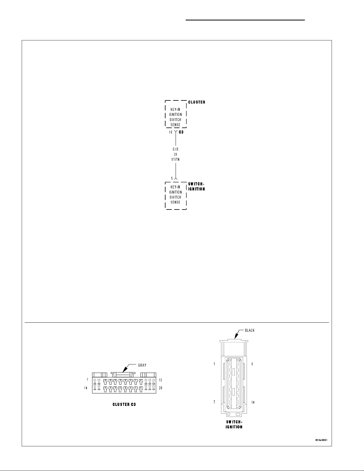
*CHIME SOUNDS WITH DRIVER DOOR OPEN KEY REMOVED
Page 3
DR/DH CHIME/BUZZER - ELECTRICAL DIAGNOSTICS 8B - 3
*CHIME SOUNDS WITH DRIVER DOOR OPEN KEY REMOVED (CONTINUED)
For the Chime system circuit diagram (Refer to 8 - ELECTRICAL/CHIME/BUZZER - SCHEMATICS AND DIAGRAMS)
For a complete wiring diagram Refer to Section 8W.
Possible Causes
KEY-IN IGN SW STATUS
IGNITION SWITCH SHORTED
(G26) KEY-IN IGNITION SW SENSE SHORT TO GROUND
CLUSTER
Diagnostic Test
READ KEY-IN IGNITION SWITCH STATUS ON DRBIII
1.
NOTE: Ensure the exterior lamps turn on and off
properly and are off before continuing this test.
With the DRBIIIT select: Electro/Mech Cluster, Input
Output.
Read the Key-In Ign Sw.
Remove the key from the ignition switch.
Does the DRBIIIT show Key-In Ign OPEN?
Yes >>
No >>
Replace and program the Cluster in accordance with the Service Information.
Perform BODY VERIFICATION TEST VER 1 (Refer to BODY VERIFICATION
TEST - VER 1).
Go To 2
Page 4
8B - 4 CHIME/BUZZER - ELECTRICAL DIAGNOSTICS DR/DH
*CHIME SOUNDS WITH DRIVER DOOR OPEN KEY REMOVED (CONTINUED)
KEY-IN IGN SWITCH SHORTED
2.
Disconnect the Ignition Switch connector.
Did the chime turn off?
Yes >>
No >>
(G26) KEY-IN IGNITION SWITCH SENSE WIRE SHORT TO GROUND
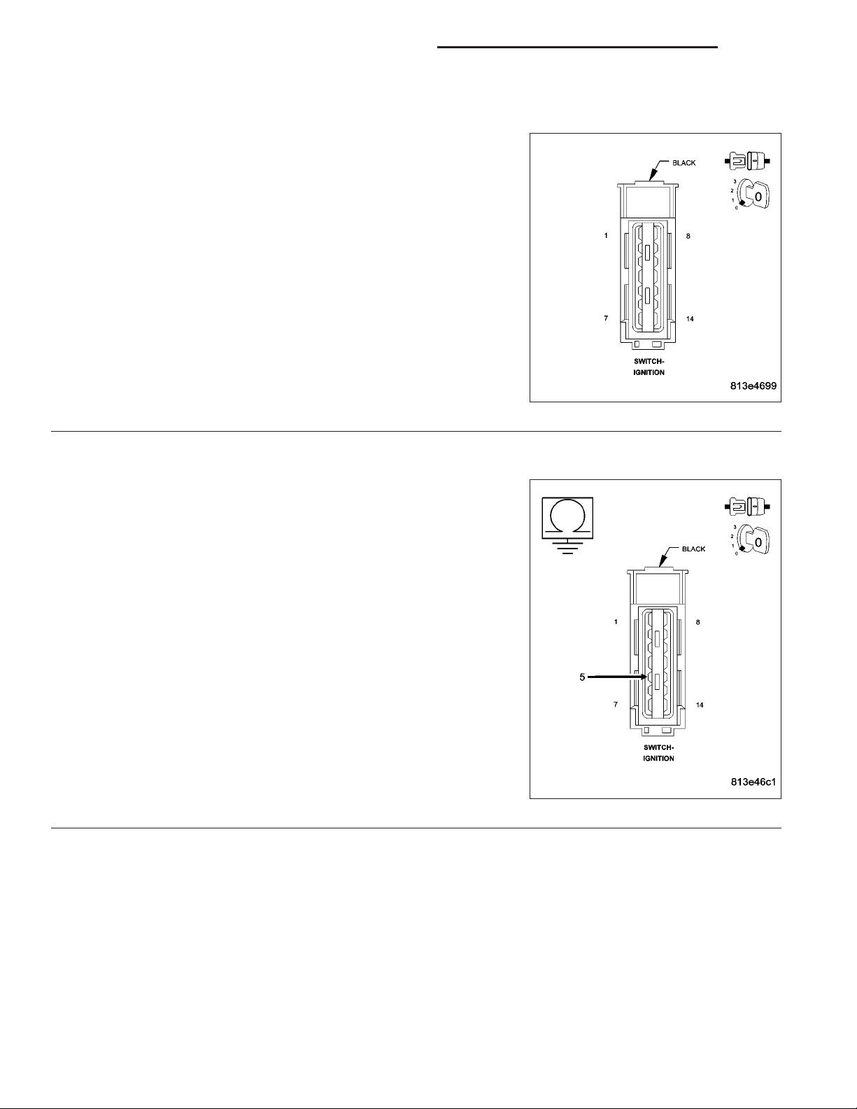
3.
Turn ignition off.
Disconnect the Ignition Switch connector.
Disconnect the Cluster C3 connector.
Measure the resistance of the (G26) Key-in Ignition Switch Sense cir-
cuit to ground at the Ignition Switch connector.
Is the resistance below 100.0 ohms?
Check the Ignition Lock Cylinder for damage. If OK
replace the Ignition Switch.
Perform BODY VERIFICATION TEST - VER 1 (Refer to
BODY VERIFICATION TEST - VER 1).
Go To 3
Yes >>
No >>
Repair the (G26) Key-In Ignition Switch Sense wire for a
short to ground.
Perform BODY VERIFICATION TEST - VER 1 (Refer to
BODY VERIFICATION TEST - VER 1).
Replace and program the Cluster in accordance with the
Service Information.
Perform BODY VERIFICATION TEST - VER 1 (Refer to
BODY VERIFICATION TEST - VER 1).
Page 5
DR/DH CHIME/BUZZER - ELECTRICAL DIAGNOSTICS 8B - 5
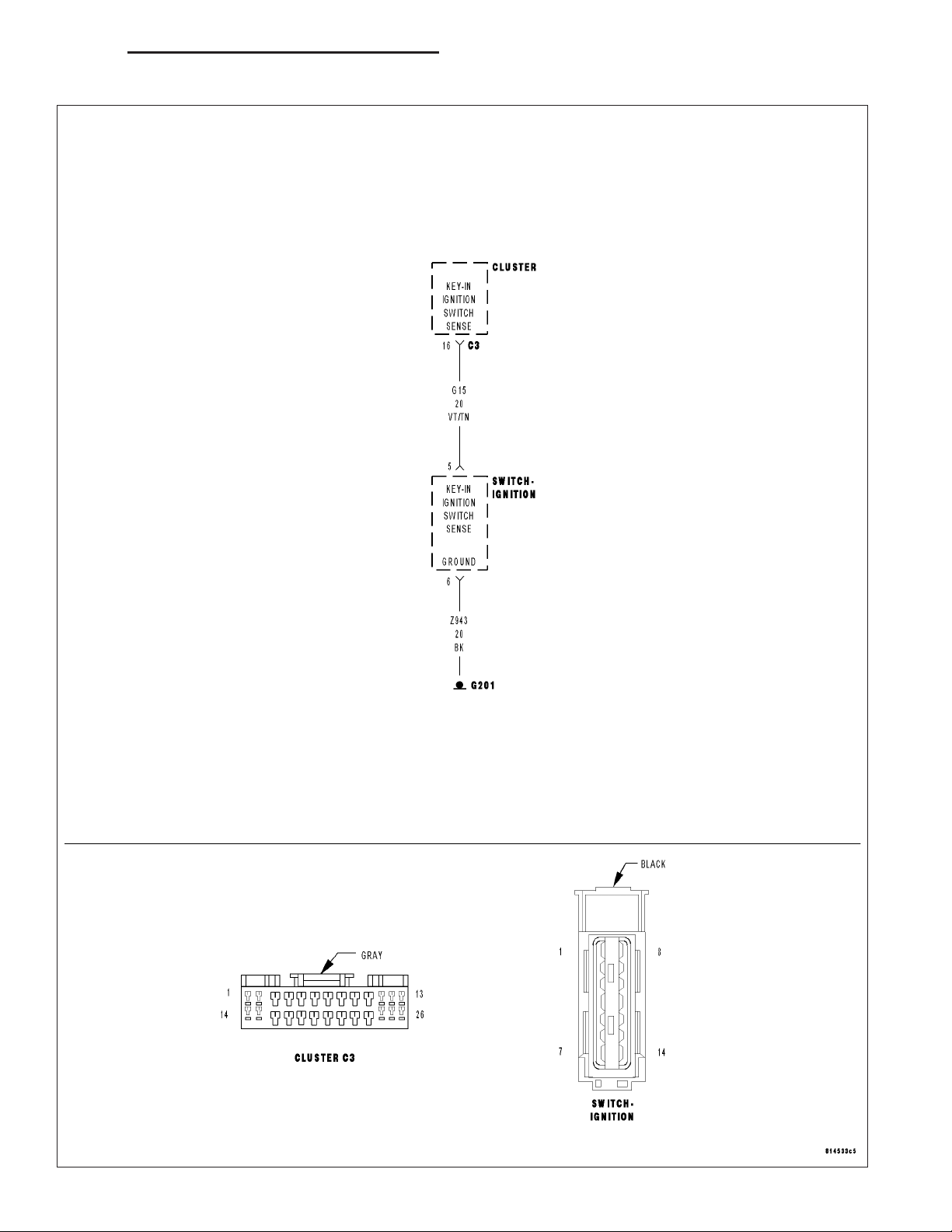
*KEY IN IGNITION AND DRIVER’S DOOR OPEN CHIME INOPERATIVE
Page 6
8B - 6 CHIME/BUZZER - ELECTRICAL DIAGNOSTICS DR/DH
*KEY IN IGNITION AND DRIVER’S DOOR OPEN CHIME INOPERATIVE (CONTINUED)
For the Chime system circuit diagram (Refer to 8 - ELECTRICAL/CHIME/BUZZER - SCHEMATICS AND DIAGRAMS)
For a complete wiring diagram Refer to Section 8W.
Possible Causes
(Z42) GROUND OPEN
(G26) KEY-IN IGNITION SWITCH OPEN
IGNITION SWITCH
CLUSTER
Diagnostic Test
READ KEY-IN IGNITION SWITCH STATUS ON DRBIII
1.
NOTE: The driver’s door ajar switch must be operational for the result of this test to be valid.
Ensure that the Key is still in the Ignition Switch.
With the DRBIIIT select: Electro/Mech Cluster, Input
Output.
Read the Key-In Ign Sw.
Does the DRBIIIT show Key-In Ign CLOSED?
Yes >>
No >>
Replace and program the Cluster in accordance with the Service Information.
Perform BODY VERIFICATION TEST VER 1 (Refer to BODY VERIFICATION
TEST - VER 1).
Go To 2
Page 7

DR/DH CHIME/BUZZER - ELECTRICAL DIAGNOSTICS 8B - 7
*KEY IN IGNITION AND DRIVER’S DOOR OPEN CHIME INOPERATIVE (CONTINUED)
IGNITION SWITCH GROUND CIRCUIT OPEN
2.
Turn the ignition off.
Disconnect the Ignition Switch connector.
Turn all lights off.
Measure the resistance between ground and the (Z42) Ground circuit
in the ignition switch harness connector.
Is the resistance below 5.0 ohms?
Yes >>
No >>
IGNITION SWITCH OPEN
3.
Connect the ignition switch connector if disconnected.
Turn ignition on.
With the ignition switch connector connected, back jumper the (G26)
Key-In Ignition Switch Sense circuit to ground at the ignition switch
connector.
With the DRBIIIT, enter Instrument Cluster Input/Outputs and observe
the Key-In Ign Sw status.
Does the DRBIII display Key-In Ign SW: Closed?
Yes >>
No >>
Go To 3
Repair the (Z42) Ground circuit for an open.
Perform BODY VERIFICATION TEST - VER 1 (Refer to
BODY VERIFICATION TEST - VER 1).
Replace the Ignition Switch.
Perform BODY VERIFICATION TEST - VER 1 (Refer to
BODY VERIFICATION TEST - VER 1).
Go To 4
Page 8

8B - 8 CHIME/BUZZER - ELECTRICAL DIAGNOSTICS DR/DH
*KEY IN IGNITION AND DRIVER’S DOOR OPEN CHIME INOPERATIVE (CONTINUED)
KEY-IN IGNITION SWITCH SENSE CIRCUIT OPEN
4.
Turn the ignition off.
Disconnect the Ignition Switch harness connector.
Disconnect the Cluster C3 harness connector.
Measure the resistance of the (G26) Key-In Ignition Switch Sense cir-
cuit between the ignition switch connector and the Instrument Cluster
C3 connector.
Is the resistance below 5.0 ohms?
Yes >>
No >>
Replace and program the Instrument Cluster in accordance with the Service Information.
Perform BODY VERIFICATION TEST - VER 1 (Refer to
BODY VERIFICATION TEST - VER 1).
Repair the (G26) Key-In Ignition Switch Sense circuit for
an open
Perform BODY VERIFICATION TEST - VER 1 (Refer to
BODY VERIFICATION TEST - VER 1).
Page 9

DR/DH CHIME/BUZZER - ELECTRICAL DIAGNOSTICS 8B - 9
*CHIME INOPERATIVE
For the Chime system circuit diagram (Refer to 8 - ELECTRICAL/CHIME/BUZZER - SCHEMATICS AND DIAGRAMS)
For a complete wiring diagram Refer to Section 8W.
Possible Causes
CLUSTER
Diagnostic Test
ACTUATE THE CHIME WITH THE DRBIII
1.
Turn the ignition on.
Close the doors.
With the DRBIIIT select: Electro/Mech Cluster and
actuate the Chime.
Does the chime sound when actuated by the
DRBIIIT?
Yes >>
No >>
If the chime operates as it should, check
for other reasons that the chime is being
inoperative.
Perform BODY VERIFICATION TEST VER 1 (Refer to BODY VERIFICATION
TEST - VER 1).
Replace and program the Cluster in accordance with the Service Information.
Perform BODY VERIFICATION TEST VER 1 (Refer to BODY VERIFICATION
TEST - VER 1).
Page 10

8B - 10 CHIME/BUZZER - ELECTRICAL DIAGNOSTICS DR/DH
*VEHICLE SPEED WARNING CHIME PROBLEM
For the Chime system circuit diagram (Refer to 8 - ELECTRICAL/CHIME/BUZZER - SCHEMATICS AND DIAGRAMS)
For a complete wiring diagram Refer to Section 8W.
Possible Causes
INCORRECT COUNTRY CODE PROGRAMMED IN CLUSTER
CLUSTER
Diagnostic Test
WITH THE DRBIII CHECK THE COUNTRY CODE SETTING
1.
NOTE: The high speed warning chime is for Gulf
Coast Countries only.
Turn the ignition on.
With the DRBIIIT in Miscellaneous check the Cluster
country code setting.
Is the country code incorrect?
Yes >>
No >>
Program the correct country code.
Perform BODY VERIFICATION TEST -
VER 1 (Refer to BODY VERIFICATION
TEST - VER 1).
Replace and program the Cluster in accordance with the Service Information.
Perform BODY VERIFICATION TEST VER 1 (Refer to BODY VERIFICATION
TEST - VER 1).
Page 11

DR/DH CHIME/BUZZER - ELECTRICAL DIAGNOSTICS 8B - 11
SCHEMATICS AND DIAGRAMS
CHIME SYSTEM
Page 12

8B - 12 CHIME/BUZZER - SERVICE INFORMATION DR/DH
CHIME/BUZZER - SERVICE INFORMATION
TABLE OF CONTENTS
page page
CHIME/BUZZER - SERVICE INFORMATION
DESCRIPTION .........................12
OPERATION ...........................13
DIAGNOSIS AND TESTING
CHIME WARNING SYSTEM ..............15
CHIME/BUZZER - SERVICE INFORMATION
DESCRIPTION
A chime warning system is standard factory-installed equipment. The chime warning system uses an electromechanical transducer and an electromechanical relay that are soldered onto the electronic circuit board inside of the
ElectroMechanical Instrument Cluster (EMIC) (1) to provide audible indications of various vehicle conditions that
may require the attention of the vehicle operator or occupants. The EMIC also includes the hardware and software
necessary to serve as the electronic body control module and is sometimes referred to as the Cab Compartment
Node or CCN.
Page 13

DR/DH CHIME/BUZZER - SERVICE INFORMATION 8B - 13
The electromechanical transducer generates beep tones and chime tones, while the electromechanical relay generates click tones to emulate the sounds associated with conventional turn signal and hazard warning flasher operation. The microprocessor-based EMIC utilizes electronic chime request messages received from other modules in
the vehicle over the Programmable Communications Interface (PCI) data bus network along with hard wired inputs
to monitor many sensors and switches throughout the vehicle. In response to those inputs, the circuitry and programming of the EMIC allow it to control the audible outputs that are produced through its on-board transducer and
relay.
The EMIC is capable of producing the following audible outputs:
• Slow Rate Repetitive Click - Repeated “click” tones that are issued at a slow rate of about 50 clicks per
minute.
• Fast Rate Repetitive Click - Repeated “click” tones that are issued at a fast rate of more than about 100
clicks per minute.
• Fixed Duration Beep - A short, sharp, single tactile “beep” tone.
• Single Chime Tone - A single “chime” tone.
• Slow Rate Repetitive Chime - Repeated “chime” tones that are issued at a slow rate of about 50 chimes per
minute.
• Fast Rate Repetitive Chime - Repeated “chime” tones that are issued at a fast rate of about 180 chimes per
minute.
Hard wired circuitry connects the EMIC and the various chime warning system switch and sensor inputs to their
modules and to each other through the electrical system of the vehicle. These hard wired circuits are integral to
several wire harnesses, which are routed throughout the vehicle and retained by many different methods. These
circuits may be connected to each other, to the vehicle electrical system and to the EMIC through the use of a
combination of soldered splices, splice block connectors, and many different types of wire harness terminal connectors and insulators. Refer to the appropriate wiring information. The wiring information includes wiring diagrams,
proper wire and connector repair procedures, further details on wire harness routing and retention, as well as pinout and location views for the various wire harness connectors, splices and grounds.
The EMIC chime warning system circuits and components cannot be adjusted or repaired. If the EMIC circuitry, the
on-board transducer or the relay are damaged or faulty, the EMIC unit must be replaced.
OPERATION
The chime warning system operates on battery voltage received through the Ignition-Off Draw (IOD) fuse in the
Power Distribution Center (PDC) on a non-switched fused B(+) circuit so that the system may operate regardless of
the ignition switch position. The chime warning system also monitors the ignition switch position so that some chime
features are functional only with the ignition switch in the On position, while others are functional regardless of the
ignition switch position.
The chime warning system provides an audible indication to the vehicle operator or occupants under the following
conditions:
• Airbag Indicator Warning - The ElectroMechanical Instrument Cluster (EMIC) transducer will generate one
short chime when the ignition switch is in the On position, and an electronic message is received over the
Programmable Communications Interface (PCI) data bus from the Airbag Control Module (ACM) requesting
“Airbag” indicator illumination. This warning will only occur following completion of the “Airbag” indicator bulb
test, and will only occur once during any ignition cycle.
• Compass Mini-Trip Computer Global Reset - The EMIC transducer will generate one short chime when the
ignition switch is in the On position, and an electronic message is received over the PCI data bus from the
optional Compass Mini-Trip Computer (CMTC) requesting that the CMTC average fuel economy, trip odometer
and distance to empty data be reset. The CMTC monitors hard wired inputs from the U.S./Metric and Reset
button switches to determine the proper reset messages to send to the EMIC.
• Door Ajar Indicator Warning - The EMIC transducer will generate one short chime when the ignition switch
is in the On position, a hard wired input is received indicating that the status of any door ajar switch has
changed, and an electronic message is received over the PCI data bus indicating that the vehicle is moving.
• Engine Coolant Temperature High Warning (Diesel Engine Only) - The EMIC transducer will generate a
single chime tone when the “Check Gauges” indicator is illuminated for a high or critical engine coolant temperature condition. The instrument cluster uses engine coolant temperature message inputs received from the
diesel Engine Control Module (ECM) over the PCI data bus to illuminate the “Check Gauges” indicator for a
coolant temperature high condition.
Page 14

8B - 14 CHIME/BUZZER - SERVICE INFORMATION DR/DH
• Fasten Seat Belt Indicator Warning - The EMIC transducer will generate repetitive chimes at a slow rate to
announce that a hard wired input from the seat belt switch indicates that the driver side front seat belt is not
fastened with the ignition switch in the On position. The chime warning system also supports the enhanced
seatbelt reminder (beltminder) when this feature is enabled. (Refer to 8 - ELECTRICAL/INSTRUMENT CLUSTER/SEATBELT INDICATOR - OPERATION).
• Head/Park Lamps-On Warning - The EMIC transducer will generate repetitive chimes at a fast rate to indi-
cate that hard wired inputs from the driver door ajar switch, the headlamp switch, and the ignition switch indicate that the exterior lamps are turned On with the driver side front door opened and the ignition switch in the
Off position. The chimes will continue to sound until the exterior lamps are turned Off, the driver side front door
is closed, or the ignition switch is turned to the On position, or the battery saver (load shed) time-out expires,
whichever occurs first.
• Key-In-Ignition Warning - The EMIC transducer will generate repetitive chimes at a fast rate to announce that
the hard wired inputs from the driver door ajar switch, the ignition switch, and the key-in ignition switch circuitry
of the ignition switch indicate that the key is in the ignition lock cylinder with the driver side front door open and
the ignition switch in the Off position. The chimes will continue to sound until the key is removed from the
ignition lock cylinder, the driver side front door is closed, or the ignition switch is turned to the On position,
whichever occurs first.
• Low Fuel Indicator Warning - The EMIC transducer will generate one short chime tone when the “Low Fuel”
indicator is illuminated by the instrument cluster circuitry. This chime will only occur once during any ignition
cycle.
• Low Oil Pressure Warning (Diesel Engine Only) - The EMIC transducer will generate repetitive chimes at a
fast rate when the “Check Gauges” indicator is illuminated for a low oil pressure condition. The instrument
cluster uses engine speed and oil pressure message inputs received from the diesel Engine Control Module
(ECM) over the PCI data bus indicating that the engine is running and that the oil pressure is low to illuminate
the “Check Gauges” indicator. The chimes will continue to sound for five seconds, until the engine oil pressure
message indicates that the oil pressure is not low, or until the engine speed message indicates that the engine
is not running, whichever occurs first. This chime will only occur once during any ignition cycle.
• Low Wash Indicator Warning - The EMIC transducer will generate one short chime when the “Low Washer
Fluid” indicator is illuminated by the instrument cluster circuitry. This chime will only occur once during any
ignition cycle.
• Overspeed Warning - The EMIC transducer will generate repetitive chimes at a slow rate to indicate that the
vehicle speed is over a pre-programmed speed value. The EMIC monitors electronic vehicle speed messages
received over the PCI data bus. This feature is only enabled on an EMIC that has been programmed with a
Middle East Gulf Coast Country (GCC) country code.
• Park Brake Reminder - The EMIC transducer will generate ten repetitive chimes at a slow rate to announce
that the hard wired input from the park brake switch and a vehicle speed message input received over the PCI
data bus indicate that the park brake is applied and the vehicle is moving. This chime will repeat each time the
input conditions are met.
• Sentry Key “Customer Learn” Mode Announcement - The EMIC transducer will generate one short chime
to confirm that an electronic “Customer Learn” mode message has been received over the PCI data bus to
indicate the Sentry Key Immobilizer Module (SKIM) is prepared for programming additional sentry key transponders. This chime feature is only active on vehicles equipped with the optional Sentry Key Immobilizer
System (SKIS), and sold in markets where “Customer Learn” programming is an allowed feature.
• Trans Overtemp Indicator Warning (Automatic Transmission Only) - The EMIC transducer will generate
repetitive chimes at a slow rate when the “Trans Temp” indicator is illuminated by the instrument cluster circuitry for a high or critical transmission fluid temperature condition. This chime will repeat each time the trans
overtemp indicator is cycled from Off to On.
• Turn Signal/Hazard Warning Flasher Emulation - The EMIC relay will generate repetitive clicks at a slow
rate to emulate an electromechanical flasher when the turn signal or hazard warning system are operating.
The EMIC relay will generate repetitive clicks at a fast rate to indicate that the right or left turn signal are
operating with one or more bulbs inoperative. In either case, the clicks will continue until the turn signal and
hazard warning systems are turned off.
Page 15

DR/DH CHIME/BUZZER - SERVICE INFORMATION 8B - 15
• Turn Signal On Warning - The EMIC transducer will generate repetitive chimes at a slow rate to indicate that
a turn signal has been active continuously for 1.6 kilometers (1 mile) with the vehicle speed greater than 22
kilometers-per-hour (15 miles-per hour). Vehicles built for markets other than the United States and Canada
have a revised distance threshold of 4 kilometers for this feature. The chime will continue until the turn signal
input becomes inactive or until the vehicle speed message indicates that the speed is less than 22 kilometersper-hour (15 miles-per-hour), whichever occurs first. The hazard warning flashers will not activate this chime
feature.
• Warning Indicator Announcement - The EMIC transducer will generate one short chime each time the
“Check Gauges” indicator is illuminated by the instrument cluster circuitry. The “Check Gauges” indicator may
be illuminated when any critical engine or transmission systems are operating outside of their normal parameters. The instrument cluster monitors electronic messages received over the PCI data bus to determine when
to illuminate the “Check Gauges” indicator.
The EMIC provides chime service for all available features in the chime warning system. The EMIC relies upon its
internal programming, numerous hard wired inputs, and electronic message inputs received from other modules
over the PCI data bus network to provide the chime warning system features. The internal programming of the
EMIC determines the priority of each chime request input that is received, as well as the rate and duration of each
chime that is to be generated.
The hard wired chime warning system inputs to the EMIC may be diagnosed and tested using conventional diagnostic tools and methods. However, conventional diagnostic methods may not prove conclusive in the diagnosis of
the EMIC, the PCI data bus, or the electronic messages received by the EMIC from other modules for control of the
chime warning system. The most reliable, efficient and accurate means to diagnose the EMIC, the PCI data bus, or
the electronic message inputs used for the chime warning system requires the use of a diagnostic scan tool. Refer
to the appropriate diagnostic information.
DIAGNOSIS AND TESTING
CHIME WARNING SYSTEM
WARNING: To avoid personal injury or death, on vehicles equipped with airbags, disable the supplemental
restraint system before attempting any steering wheel, steering column, airbag, seat belt tensioner, impact
sensor, or instrument panel component diagnosis or service. Disconnect and isolate the battery negative
(ground) cable, then wait two minutes for the system capacitor to discharge before performing further diagnosis or service. This is the only sure way to disable the supplemental restraint system. Failure to take the
proper precautions could result in accidental airbag deployment.
The hard wired chime warning system inputs to the ElectroMechanical Instrument Cluster (EMIC), as well as other
hard wired circuits for this system may be diagnosed and tested using conventional diagnostic tools and methods.
Refer to the appropriate wiring information. The wiring information includes wiring diagrams, proper wire and connector repair procedures, details of wire harness routing and retention, connector pin-out information and location
views for the various wire harness connectors, splices and grounds.
However, conventional diagnostic methods may not prove conclusive in the diagnosis of the EMIC, the Programmable Communications Interface (PCI) data bus, or the electronic message inputs used by the EMIC to provide
chime warning system service. The most reliable, efficient, and accurate means to diagnose the EMIC, the PCI data
bus, and the electronic message inputs for the chime warning system requires the use of a diagnostic scan tool.
Refer to the appropriate diagnostic information.
Page 16

8B - 16 CHIME/BUZZER - SERVICE INFORMATION DR/DH
CONDITION POSSIBLE CAUSES CORRECTION
NO SEAT BELT WARNING
CHIME WITH SEAT BELT
UNBUCKLED, BUT OTHER
CHIME FEATURES OK
SEAT BELT WARNING CHIME
WITH SEAT BELT BUCKLED
1. Seat belt switch ground
circuit open.
2. Seat belt switch sense circuit
open.
3. Faulty seat belt switch. 3. Check for continuity between the ground
1. Seat belt switch sense circuit
shorted.
2. Faulty seat belt switch. 2. Check for continuity between the ground
1. Check for continuity between the ground
circuit for the driver seat belt switch and a
good ground. Repair open ground circuit, if
required.
2. Check for continuity between the seat
belt switch sense circuit for the driver seat
belt switch and the instrument cluster
connector. Repair the open seat belt switch
sense circuit, if required.
circuit and the driver seat belt switch sense
circuit of the seat belt switch. There should
be continuity with the seat belt unbuckled.
Replace the faulty seat belt, if required.
1. With the driver seat belt switch and the
instrument cluster connector disconnected,
there should be no continuity between the
seat belt switch sense circuit and a good
ground. Repair the shorted seat belt switch
sense circuit, if required.
circuit cavity and the seat belt switch sense
circuit of the driver seat belt switch. There
should be no continuity with the seat belt
buckled. Replace the faulty seat belt, if
required.
NO KEY-IN IGNITION
WARNING CHIME, BUT
OTHER CHIME FEATURES OK
1. Driver door ajar switch sense
circuit open.
2. Key-in ignition switch sense
circuit open.
3. Key-in ignition switch ground
circuit open.
4. Faulty ignition switch. 4. Check for continuity between the ground
1. Check for continuity between the driver
door ajar switch sense circuit connector and
the instrument cluster connector. Repair the
open driver door ajar switch sense circuit, if
required.
2. Check for continuity between the key-in
ignition switch sense circuit connector and
instrument cluster connector. Repair the
open key-in ignition switch sense circuit, if
required.
3. Check for continuity between the ground
circuit cavity of the ignition switch connector
and a good ground. Repair the open ground
circuit, if required
circuit terminal and the key-in ignition switch
sense circuit terminal in the ignition switch
connector. There should be continuity with a
key in the ignition lock cylinder. Replace the
faulty ignition switch, if required.
Page 17

DR/DH CHIME/BUZZER - SERVICE INFORMATION 8B - 17
CONDITION POSSIBLE CAUSES CORRECTION
NO EXTERIOR LAMPS-ON
WARNING CHIME, BUT
OTHER CHIME FEATURES OK
NO CHIMES AND OTHER
INSTRUMENT CLUSTER
FEATURES ERRATIC OR
DISABLED
1. Driver door ajar switch sense
circuit open.
2. Headlamp switch signal
circuit open.
1. Instrument cluster ground
circuit(s) open.
2. Instrument cluster fused B(+)
circuit(s) open.
3. Instrument cluster fused
ignition switch output (run-start)
circuit open.
4. Faulty instrument cluster. 4. Replace the faulty instrument cluster, if
1. Check for continuity between the driver
door ajar switch sense circuit connector and
the instrument cluster connector. Repair the
open driver door ajar switch sense circuit, if
required.
2. Check for continuity between the
headlamp switch output circuit connector
and the and the instrument cluster
connector. Repair the open headlamp
switch signal circuit, if required.
1. Check for continuity between the ground
circuits of the instrument cluster connector
and a good ground. Repair the open ground
circuits(s), if required.
2. Check for battery voltage at the B(+)
circuits of the instrument cluster connector.
Repair the open fused B(+) circuit(s), if
required.
3. With the ignition switch in the On
position, check for battery voltage at the
fused ignition switch output (run-start) circuit
of the instrument cluster connector. Repair
the open fused ignition switch output
(run-start) circuit, if required.
required.
NO CHIMES, BUT ALL OTHER
INSTRUMENT CLUSTER
FEATURES OK
1. Faulty instrument cluster. 1. Replace the faulty instrument cluster, if
required.
Page 18

 Loading...