

Page 1
2015
CHARGER
USER
GUIDE
INCLUDES SRT 392/SRT HELLCAT
Page 2
IMPORTANT
This U s er G ui d e is i n tend ed to f am il iari ze you wi th the i mp orta nt feat ur e s
of y o ur v e hicl e. Th e DVD e n clos ed co nt a ins your O wner ’s M anu al ,
Navigation/Uconnect
Road si d e A s sist an c e ( n ew v ehic le s p ur ch ased in t he U . S.) or R oads id e
Assi st a nce ( new v ehic le s pu rc ha sed i n Ca na d a) i n el e ctro ni c fo rm at . We
hope yo u fi nd i t us ef u l. Rep la ce ment DVD ki ts ma y be pu rc ha sed by vis it i ng
www.techauthority.com. D O DGE a nd C h arge r are r egis te r ed t r adem ar k s
of Chrysler Group LLC. Copyright 2014 Chrysler Group LLC.
If you are the rst registered retail owner of your vehicle, you may
obtain a complimentary printed copy of the Owner’s Manual,
Navigation/Uconnect
1-800-423-6343 (U.S.) or 1-800-387-1143 (Canada) or by
contacting your dealer.
®
M a nual s, W arra nt y B oo k lets , Ti r e Warr an t y a nd
®
Manuals or Warranty Booklet by calling
T h e driver ’s p ri ma r y re spons ib il i t y
is the s afe o p eration of the
v ehicle . D r i ving w hile d is tracted
c an re sul t in l o s s o f v eh ic le
c o n t r o l, r e su l t ing in a c ol li si o n
and p e r s o nal inju ry. C hr y sler
G r o up L LC s tr on gl y re comm en ds
that t he d r i v e r u se e xtreme
c aution when usi ng an y d ev ic e or
f e a ture t hat m ay t a k e t h e i r
a t t e n t ion of f t h e ro ad . U s e of a n y
e le c t r i cal d evice s, s u ch a s
c e llul ar t ele ph ones, comp ute rs,
p o r ta bl e r ad io s, vehi cl e nav ig at io n
o r o th er d e v i c e s , b y t he d r i v e r
w hile the v ehi cl e is m ovi ng i s
dang er ous a nd c ou ld l e a d t o a
s e r i ous coll is io n. T ex tin g w hi le
driving is als o da ng er ous and
should n ev er b e d on e w hi l e t h e
v ehicle i s moving . I f yo u f in d
y o ur s elf una bl e to d ev ote y our fu ll
a t t e n t ion t o v eh ic le o p e r ation,
pull o ff t he r o a d t o a s a f e l ocati on
and s to p y o ur v eh ic le . S om e s t ates
o r p r o v ince s p r o h ibit the use o f
c e llul ar telep ho nes o r t e x ti ng
w hile dr iv in g. I t i s a lw ay s t he
driver ’s r esp ons ib il i t y t o c omp ly
with all local laws.
Page 3

TABLE OF CONTENTS
INTRODUCTION/WELCOME
WELCOME FROM CHRYSLER
GROUP LLC ..................3
CONTROLS AT A GLANCE
DRIVER COCKPIT ...............6
INSTRUMENT CLUSTER ...........8
GETTING STARTED
KEY FOB . . . . . . . . . . . . . . . . . . . 10
REMOTE STAR T . . . . . . . . . . . . . . . 13
KEYLESS ENTER-N-GO™ .........14
TRUNK LOCK AND RELEASE .......17
VEHICLE SECURITY ALARM ........18
SEA T BELT SYSTEMS ............19
SUPPLEMENTAL RESTRAINT SYSTEM
(SRS) — AIR BAGS .............20
CHILD RESTRAINTS ............23
HEAD RESTRAINTS .............27
FRONT SEA TS ................28
REAR SEA TS .................31
HEA TED/VENTILATED SEATS ........32
HEA TED STEERING WHEEL ........34
ADJUSTABLE PEDALS ........... 35
TIL T/TELESCOPING STEERING
COLUMN ...................36
OPERATING YOUR VEHICLE
ENGINE BREAK-IN
RECOMMENDA TIONS ............38
TURN SIGNAL/WIPER/WASHER/HIGH
BEAM LEVER .................41
HEADLIGHT SWITCH ............ 42
ELECTRONIC SPEED CONTROL ......43
ADAPTIVE CRUISE CONTROL (ACC) ....45
LANESENSE ................. 51
BLIND SPOT MONITORING ......... 52
EIGHT -SPEED AUTOMATIC
TRANSMISSION ...............52
STEERING WHEEL MOUNTED PADDLE
SHIFTERS ...................53
SPORT MODE — WITHOUT PERFORMANCE
CONTROL ...................55
MANUAL CLIMA TE CONTROLS .......55
AUTOMA TIC TEMPERATURE CONTROLS
(A TC) . . . . . . . . . . . . . . . . . . . . . . 57
POWER SUNROOF ..............60
WIND BUFFETING ..............61
ELECTRONICS
YOUR VEHICLE'S SOUND SYSTEM ....62
IDENTIFYING YOUR RADIO .........64
®
Uconnect
Uconnect
Uconnect
Uconnect
ACCESS .............65
®
5.0 . . . . . . . . . . . . . . . . 81
®
8.4A ...............92
®
8.4AN .............119
®
Uconnect
STEERING WHEEL AUDIO CONTROLS
DRIVER INFORMA TION DISPLAY (DID)
PROGRAMMABLE FEA TURES .......148
UNIVERSAL GARAGE DOOR OPENER . . 150
POWER OUTLET ..............152
PHONE ............. 133
..143
..144
UTILITY
TRAILER TOWING WEIGHTS (MAXIMUM
TRAILER WEIGHT RA TINGS) ....... 154
RECREA TIONAL TOWING (BEHIND
MOTORHOME, ETC.) ............154
SRT
AUTOSTICK
DRIVE MODES ................ 157
SRT PERFORMANCE FEATURES .....157
SUMMER/THREE-SEASON TIRES ....160
®
................155
WHAT TO DO IN EMERGENCIES
ROADSIDE ASSISTANCE ..........161
INSTRUMENT CLUSTER WARNING
LIGHTS ................... 161
INSTRUMENT CLUSTER INDICA TOR
LIGHTS ................... 165
IF YOUR ENGINE OVERHEA TS ......167
JACKING AND TIRE CHANGING .....168
TIRE SERVICE KIT .............175
BA TTERY LOCATION ............181
JUMP-STAR TING .............. 181
MANUAL PARK RELEASE — 8 SPEED
TRANSMISSION ...............184
TOWING A DISABLED VEHICLE .....186
FREEING A STUCK VEHICLE .......187
EVENT DA TA RECORDER (EDR) .....188
MAINTAINING YOUR VEHICLE
OPENING THE HOOD ...........189
ENGINE COMPAR TMENT .........190
FLUID CAPACITIES — NON-SRT .....198
FLUID CAPACITIES — SRT ........198
FLUIDS, LUBRICANTS AND GENUINE
PART S — NON -SRT ............ 199
FLUIDS, LUBRICANTS AND GENUINE
PART S — SRT . . . . . . . . . . . . . . . 200
MAINTENANCE PROCEDURES ......202
MAINTENANCE SCHEDULE —
NON-SRT ...................202
MAINTENANCE SCHEDULE —
SRT . . . . . . . . . . . . . . . . . . . . . . 207
FUSES ....................215
TIRE PRESSURES .............220
SPARE TIRES — IF EQUIPPED ......221
FUEL DOOR RELEASE ..........222
WHEEL AND WHEEL TRIM CARE ....224
REPLACEMENT BULBS ..........224
Page 4

TABLE OF CONTENTS
CONSUMER ASSISTANCE
CHRYSLER GROUP LLC CUSTOMER
CENTER ...................225
CHRYSLER CANADA INC. CUSTOMER
CENTER ...................225
ASSISTANCE FOR THE HEARING
IMPAIRED ..................225
PUBLICA TIONS ORDERING ........225
REPORTING SAFETY DEFECTS IN THE
UNITED STATES ...............226
MOPAR® ACCESSORIES
AUTHENTIC ACCESSORIES BY
®
MOPAR
...................227
FREQUENTLY ASKED QUESTIONS
FAQ ’s . . . . . . . . . . . . . . . . . . . . . 22 8
INDEX
.....................229
2
Page 5

INTRODUCTION/WELCOME
WELCOME FROM CHRYSLER GROUP LLC
Congratulations on selecting your new Chrysler Group LLC vehicle. Be assured that it
represents precision workmanship, distinctive styling, and high quality - all essentials that
are traditional to our vehicles.
Your new Chrysler Group LL C vehic le has ch aracter istics to enhanc e the dri ver's c ontrol
under some driving conditions. These are to assist the driver and are never a substitute for
attentive driving. They can never take the driver's place. Always drive carefully.
Your new v ehicle h as ma ny fe atures f or th e comfor t and c on venienc e of you a nd your
passengers. Some of these should not be used when driving because they take your eyes
from the road or your attention from driving. Never text while driving or take your eyes more
than momentarily off the road.
This guide illustrates and describes the operation of features and equipment that are
either standard or optional on this vehicle. This guide may also include a description of
features and equipment that are no longer available or were not ordered on this vehicle.
Please disregard any features and equipment described in this guide that are not available
on this vehicle. Chrysler Group LLC reserves the right to make changes in design and
specifications and/or make additions to or improvements to its products without imposing
any obligation upon itself to install them on products previously manufactured.
This User Guide has been prepared to help you quickly become acquainted with the
important features of your vehicle. It contains most things you will need to operate and
maintain the vehicle, including emergency information.
The DVD includes a computer application containing detailed owner's information which
can be viewed on a personal computer or MAC computer. The multimedia DVD also
includes videos which can be played on any standard DVD player (including the
Uconnect
DVD operational information is located on the back of the DVD sleeve.
For complete owner information, refer to your Owner's Manual on the DVD in the owner’s
kit provided at the time of new vehicle purchase. For your convenience, the information
contained on the DVD may also be printed and saved for future reference.
Chrysler Group LLC is committed to protecting our environment and natural resources. By
converting from paper to electronic delivery for the majority of the user information for
your vehicle, together we greatly reduce the demand for tree-based products and lessen
the stress on our environment.
®
Touc hsc r een R adi os if equ i ppe d w i th DVD pla y er cap a bil iti e s). Add i tio nal
3
Page 6

INTRODUCTION/WELCOME
VEHICLES SOLD IN CANADA
With respect to any vehicles sold in Canada, the name Chrysler Group LLC shall be
deemed to be deleted and the name Chrysler Canada Inc. used in substitution (excluding
legal lines).
WARNING!
•Pedalsthatcannotmovefreelycancauselossofvehiclecontrolandincreasethe
risk of serious personal injury.
•Alwaysmakesurethatobjectscannotfallintothedriverfootwellwhilethevehicle
is moving. Objects can become trapped under the brake pedal and accelerator
pedal causing a loss of vehicle control.
•Failuretoproperlyfollowfloormatinstallationormountingcancauseinterference
with the brake pedal and accelerator pedal operation causing loss of control of the
vehicle.
•Neverleavechildrenaloneinavehicle,orwithaccesstoanunlockedvehicle.
Allowing children to be in a vehicle unattended is dangerous for a number of
reasons. A child or others could be seriously or fatally injured. Children should be
warned not to touch the parking brake, brake pedal or the shift lever/transmission
gear selector.
•Donotleavethekeyfobinornearthevehicle,orinalocationaccessibletochildren,
and do not leave the ignition of a vehicle equipped with Keyless Enter-N-Go in the
ACC or ON/RUN mode. A child could operate power windows, other controls, or
move the vehicle.
•Neverusethe“PARK”positionasasubstitutefortheparkingbrake.Alwaysapply
the parking brake fully when parked to guard against vehicle movement and
possible injury or damage.
•RefertoyourOwner'sManualontheDVDforfurtherdetails.
4
Page 7

INTRODUCTION/WELCOME
USE OF AFTERMARKET PRODUCTS (ELECTRONICS)
The use of aftermarket devices including cell phones, MP3 players, GPS systems, or
chargers may affect the performance of on-board wireless features including Keyless
Enter-N-Go™ and Remote Start range. If you are experiencing difficulties with any of your
wireless features, try disconnecting your aftermarket devices to see if the situation
improves. If your symptoms persist, please see an authorized dealer.
CHRYSLER, DODGE, JEEP, RAM, MOPAR and Uconnect are registered trademarks of
Chrysler Group LLC.
COPYRIGHT ©2014 CHRYSLER GROUP LLC
5
Page 8
CONTROLS AT A GLANCE
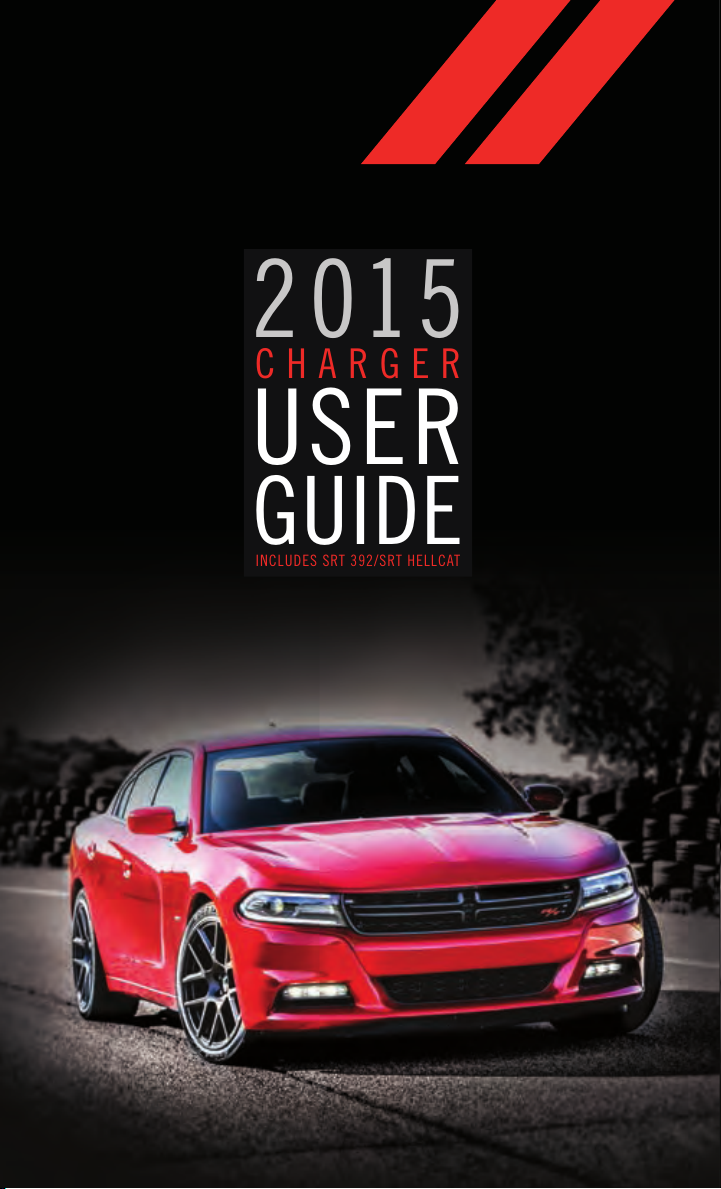
DRIVER COCKPIT
1. Driver Memory Seat pg. 29
2. Headlight Switch pg. 42
3. Paddle Shifters pg. 53
4. Instrument Cluster pg. 8
5. Driver Information Display (DID) pg. 144
6. Engine Start/Stop Button pg. 16
7. Your Vehicle's Sound System pg. 62
8. Manual Audio Controls
9. Glove/Storage Compartment
10. Climate Controls pg. 57
6
Page 9

CONTROLS AT A GLANCE
11. Power Outlet pg. 152
12. Shift Lever pg. 52
13. Speed Control pg. 43
14. Driver Information Display (DID) Controls pg. 144
15. Emergency Brake Pedal
16. Hood Release
17. Power Door Lock Switches
18. Power Window Switches
19. Power Mirrors Switch
7
Page 10
CONTROLS AT A GLANCE
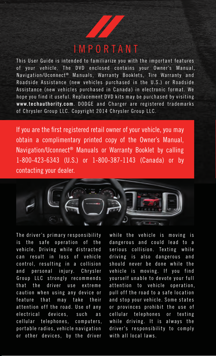
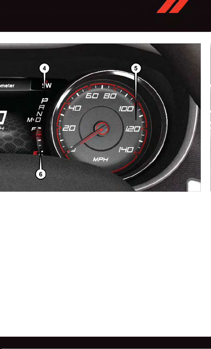
INSTRUMENT CLUSTER
1. Engine Coolant Temperature Gauge
2. Tachometer
3. Driver Information Display (DID)
(See page 161 for Instrument Cluster Warning descriptions information.)
8
Page 11
CONTROLS AT A GLANCE
4. Gear Selector Position
5. Speedometer
6. Fuel Filler Location/Fuel Gauge
(See page 165 for Instrument Cluster Indicator descriptions information.)
9
Page 12
GETTING STARTED
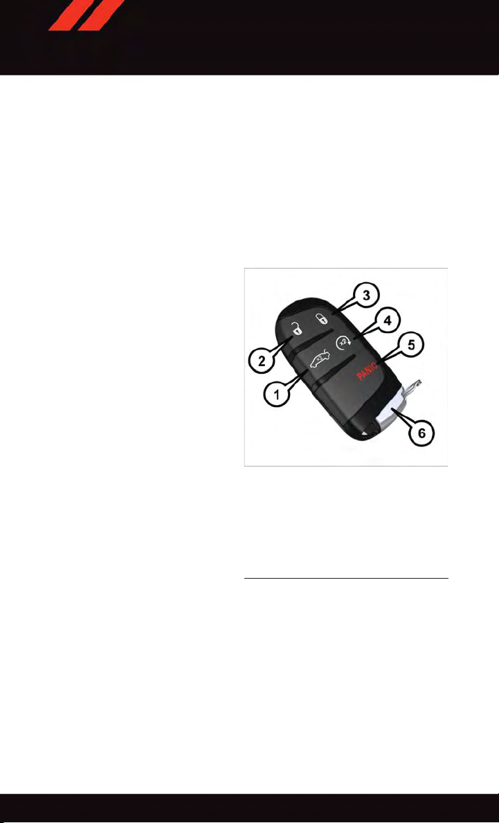
KEY FOB
The Key Fob contains the Remote Keyless Entry (RKE) transmitter and an emergency key,
which stores in the rear of the Key Fob.
The emergency key allows for entry into the vehicle should the battery in the vehicle or the
Key Fob go dead. The emergency key is also for locking/unlocking the glove compartment.
You can keep the emergenc y k ey with you when valet parkin g.
To rem ove t he e m erg ency k ey, s l ide t he m echa nic a l la t ch o n the b ack o f the K ey F ob
sideways with your thumb and then pull the key out with your other hand.
Base Key Fob
10
Base Key Fob
1—Decklid
2—Unlock
3—Lock
4—RemoteStart
5—PanicAlarm
6—EmergencyKey
Page 13
GETTING STARTED
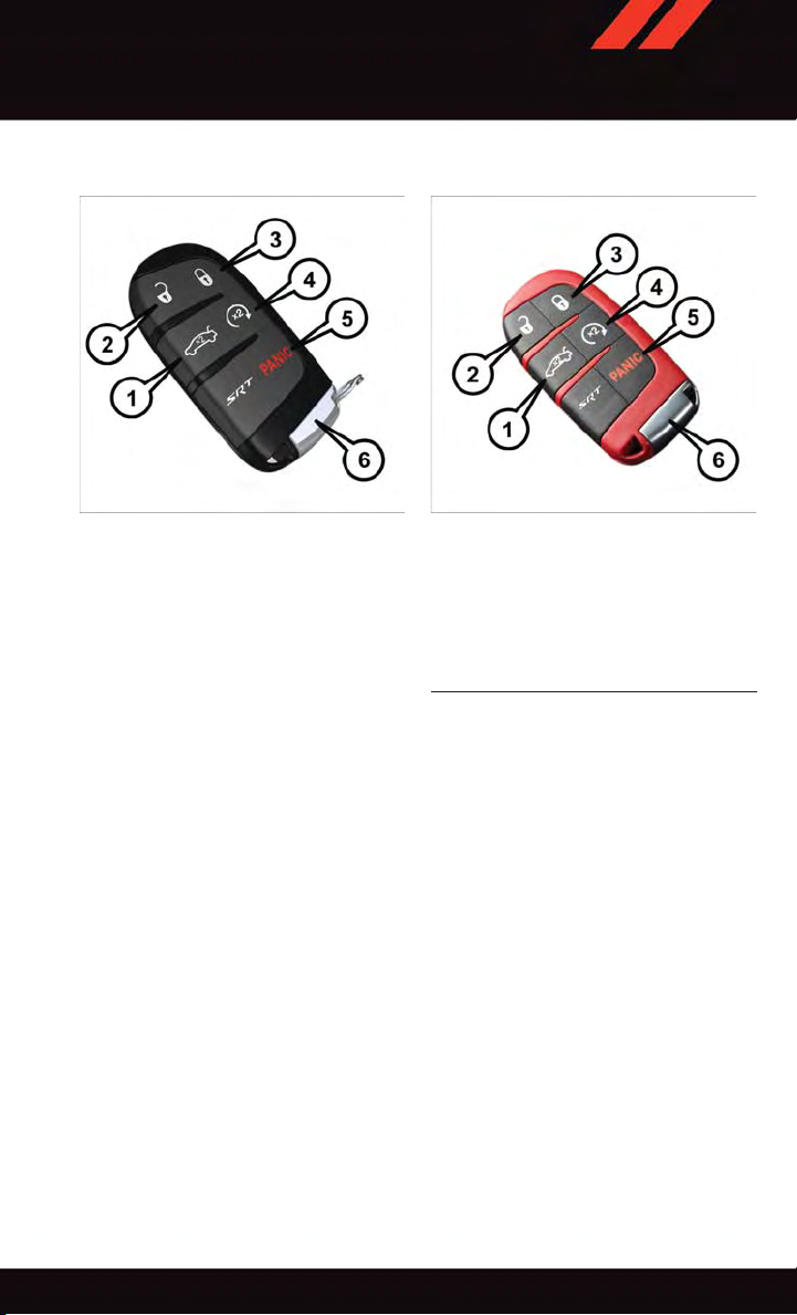
SRT Key Fobs
SRT 392 Key Fob SRT Hellcat Key Fob
1—Decklid
2—Unlock
3—Lock
4—RemoteStart
5—PanicAlarm
6—EmergencyKey
NOTE:
SRT vehicle equipped with the 6.2L Supercharged engine come with three key fobs (two
red and one black) that allow for different engine power levels. Please refer to the "Drive
Modes" in “SRT” section in this guide for further descriptions
11
Page 14
GETTING STARTED
Locking And Unlocking The Doors
Push and release the LOCK button on the RKE transmitter to lock all doors. The turn
signal lights will flash, and the horn will chirp to acknowledge the signal.
Push and release the UNLOCK
driver's door or twice within five seconds to unlock all doors. The turn signal lights will
flash to acknowledge the unlock signal. The illuminated entry system will also turn on.
1st Press Of Key Fob Unlocks
This feature lets you program the system to unlock either the driver's door or all doors on
the first push of the UNLOCK button on the RKE transmitter. To change the current
setting, refer to your “Uconnect
your Owner's Manual on the DVD for further information.
Opening The Trunk
Push the Trunk Release button on the transmitter two times within five seconds to open
the trunk.
Panic Alarm
1. Push the P ANIC button once to turn the panic alarm on.
2. Wait approximately three seconds and push the button a second time to turn the panic
alarm off.
button on the RKE transmitter once to unlock the
®
Settings” in “Understanding Your Instrument Panel” in
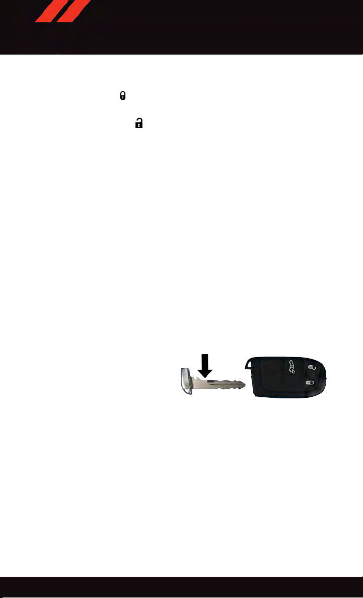
Emergency Key
Should the battery in the vehicle or the Key
Fob transmitter go dead, there is an emergency key located in the Key Fob.
•Toremovetheemergencykey,slidethe
button at the back of the Key Fob sideways with your thumb and then pull the
key out with your other hand.
The emergency key is also for locking the glove compartment.
12
Emergency Key
Page 15
GETTING STARTED
WARNING!
•NeverusethePARKpositionasasubstitutefortheparkingbrake.Alwaysapplythe
parking brake fully when parked to guard against vehicle movement and possible
injury or damage.
•Whenleavingthevehicle,alwaysmakesuretheKeylessIgnitionNodeisinthe
“OFF” mode and remove the Key Fob from the vehicle.
•Neverleavechildrenaloneinavehicle,orwithaccesstoanunlockedvehicle.
Allowing children to be in a vehicle unattended is dangerous for a number of
reasons. A child or others could be seriously or fatally injured. Children should be
warned not to touch the parking brake, brake pedal or the gear selector.
•DonotleavetheKeyFobinornearthevehicle,orinalocationaccessibleto
children, and do not leave the ignition of a vehicle equipped with Keyless
Enter-N-Go™ in the ACC or ON/RUN mode. A child could operate power windows,
other controls, or move the vehicle.
REMOTE START
x
•PushtheREMOTESTARTbutton
Pushing the REMOTE START button a third time shuts the engine off.
•Todrivethevehicle,pushtheUNLOCKbuttonandcycletheignitiontotheON/RUN
position.
With Remote Start, the engine will only run for 15 minutes (timeout) unless the ignition
is cycled to the ON/RUN position.
The vehicle must be cycled to the ON/RUN position after two consecutive timeouts.
2
on the Key Fob twice within five seconds.
WARNING!
•Donotstartorrunanengineinaclosedgarageorconfinedarea.Exhaustgas
contains Carbon Monoxide (CO) which is odorless and colorless. Carbon Monoxide
is poisonous and can cause you or others to be severely injured or killed when
inhaled.
•KeepKeyFobtransmittersawayfromchildren.OperationoftheRemoteStart
System, windows, door locks or other controls could cause you and others to be
severely injured or killed.
13
Page 16
GETTING STARTED
KEYLESS ENTER-N-GO™
The Keyless Enter-N-Go™ system is an enhancement to the vehicle's Key Fob. This
feature allows you to lock and unlock the vehicle's door(s) and trunk without having to
push the Key Fob lock or unlock buttons as well as starting and stopping the vehicle with
the push of a button.
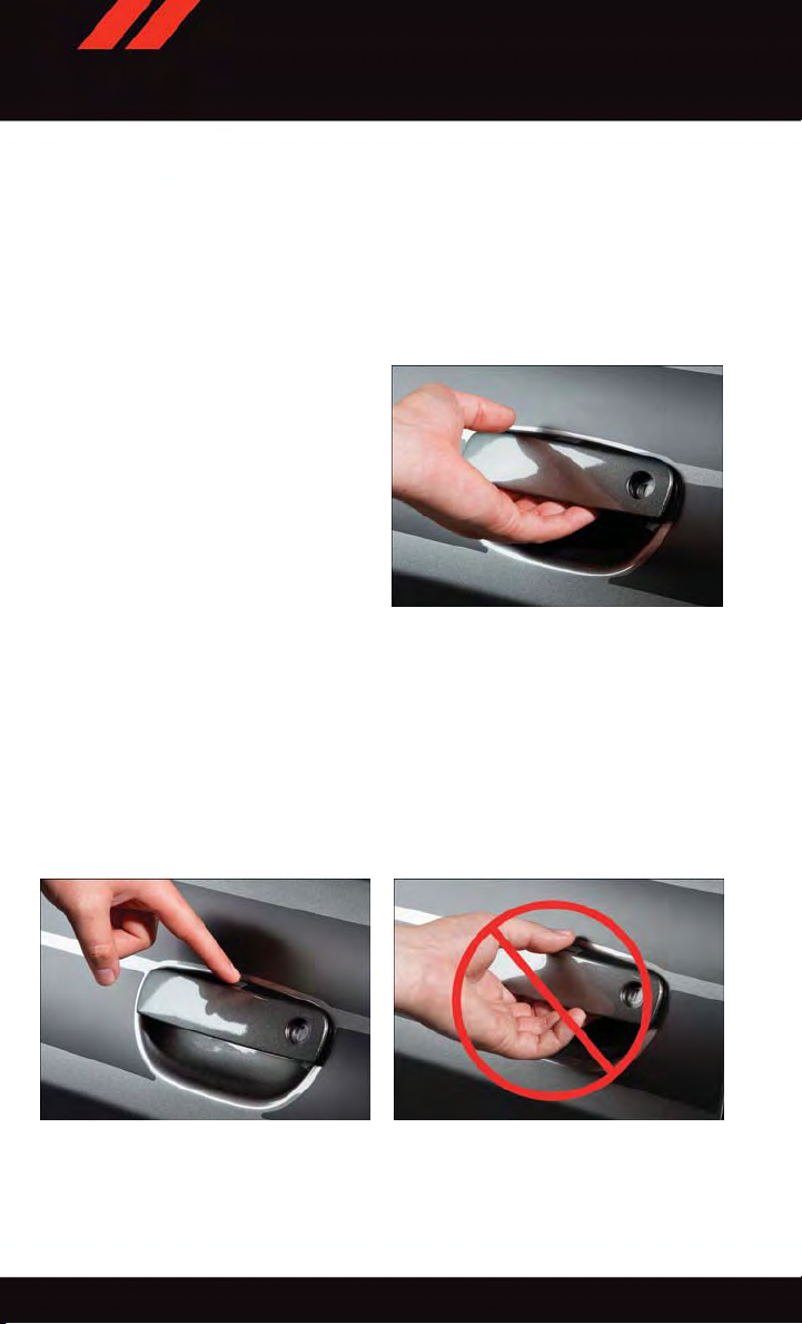
To Unlock From The Driver Or Passenger Side:
•WithavalidKeylessEnter-N-Go™Key
Fob located outside the vehicle and
within 5 ft (1.5 m) of the driver or passenger side door handle, lift either front
door handle to unlock the door
automatically.
Lift The Door Handle To Unlock
To Lock The Vehicle
•Bothfrontdoorhandleshavebuttonslocatedontheoutsideofthehandle.Withoneof
the vehicle's Keyless Enter-N-Go™ Key Fobs located outside the vehicle and within 5
ft (1.5 m) of the driver's or passenger front door handle, push the door handle button to
lock all four doors and trunk.
•DoNOTgrabthedoorhandlewhenpushingthedoorhandlelockbutton.Thiscould
unlock the door(s).
Push The Door Handle Button To Lock Do NOT Grab The Handle When Locking
14
Page 17
GETTING STARTED
NOTE:
If “Unlock All Doors 1st Press” is programmed, all doors will unlock when you grab hold
•
of the front driver's door handle. To select between “Unlock Driver Door 1st Press” and
“Unlock All Doors 1st Press,” refer to the “Uconnect
Manual on the DVD or “Programmable Features” in this guide for further information.
•IfaKeyFobisdetectedinthevehiclewhenlockingthevehicleusingthepowerdoor
lock switch, the doors will unlock and the horn will chirp three times. On the third
attempt, your Key Fob can be locked inside the vehicle.
•AfterpushingtheKeylessEnter-N-Go™LOCKbutton,youmustwaittwoseconds
before you can lock or unlock the vehicle using the door handle. This is done to allow
you to check if the vehicle is locked by pulling the door handle without the vehicle
reacting and unlocking.
•IfaKeylessEnter-N-Go™doorhandlehasnotbeenusedfor72hours,theKeyless
Enter-N-Go™ feature for that handle may time out. Pulling the deactivated front door
handle will reactivate the door handle's Keyless Enter-N-Go™ feature.
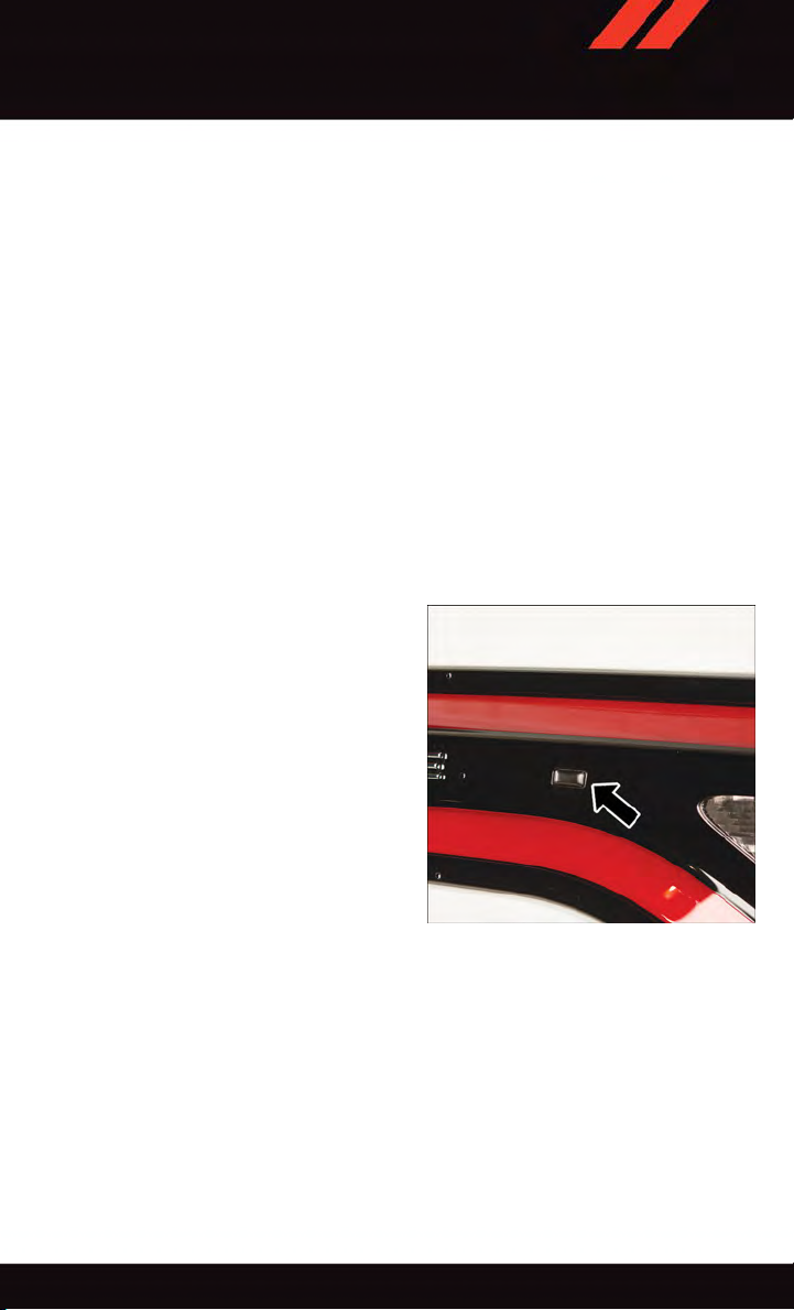
To Enter The Trunk
•WithavalidKeylessEnter-N-Go™Key
Fob located outside the vehicle and
within 5 ft (1.5 m) of the deck lid, push
the button on the right side of applique
which is located on the deck lid.
•Wheneverthevehicleisunlocked,you
can enter the trunk by pushing the button on the right side of the applique.
NOTE:
Refer to your Owner's Manual on the DVD
for further information.
®
Settings” in your vehicle's Owner's
Trunk Passive Entry Button
15
Page 18
GETTING STARTED
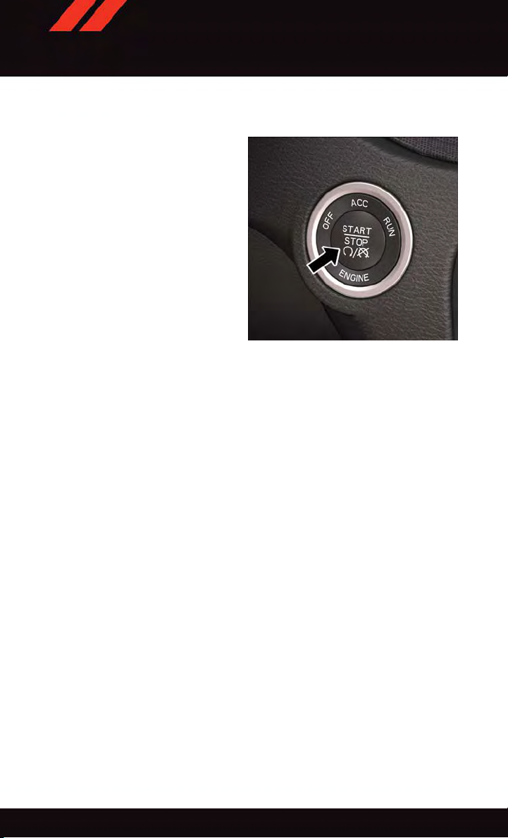
Engine Starting/Stopping
Starting
With a valid Keyless Enter-N-Go™ Key Fob
inside the vehicle:
1. Shift the transmission into P ARK or
NEUTRAL.
2. While pushing the brake pedal, push the
ENGINE STAR T/STOP button once. If
the engine fails to start, the starter will
disengage automatically after 10 seconds.
3. To stop the cranking of the engine prior
to the engine starting, push the button
again.
NOTE:
In case the ignition switch does not change with the push of a button, the RKE transmitter
(Key Fob) may have a low or dead battery . In this situation a back up method can be used
to operate the ignition switch. Put the nose side of the Key Fob (side opposite of the
Emergency Key) against the ENGINE START/STOP button and push to operate the
ignition switch.
Stopping
1. Bring the vehicle to a complete stop.
2. Shift the transmission to PARK (P).
3. Push the ENGINE STAR T/STOP button once. The ignition switch will return to the OFF
position.
NOTE:
If the transmission is not in P ARK and the vehicle is in motion, the ENGINE STAR T/
STOP button must be held for two seconds with the vehicle speed above 5 mph (8
km/h) before the engine will shut off.
Engine START/STOP Button
Accessory Positions With Engine Off
NOTE:
The following functions are with the driver’s foot off of the Brake Pedal (transmission in
PARK o r NEUTR AL).
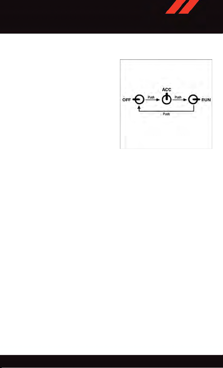
Beginning With The Ignition Switch In The OFF Position:
1. Push the ENGINE STAR T/STOP button once to cycle the ignition to the ACC position.
2. Push the ENGINE START/STOP button a second time to cycle the ignition to the
ON/RUN position.
16
Page 19
GETTING STARTED
3. Push the ENGINE START/STOP button a third time to return the ignition to the OFF
position.
NOTE:
If the ignition is left in the ACC or ON/RUN
(engine not running) position and the transmission is in PARK, the system will automatically time out after 30 minutes of inactivity, and the ignition is returned to the OFF
position.
Ignition Positions
TRUNK LOCK AND RELEASE
•ThetrunklidcanbereleasedfrominsidethevehiclebypushingtheTRUNKRELEASE
button located on the instrument panel to the left of the steering wheel.
NOTE:
The transmission must be in PARK before the button will operate.
•ThetrunklidcanbereleasedfromoutsidethevehiclebypushingtheTRUNKbutton
on the Remote Keyless Entry (RKE) transmitter twice within five seconds.
•WiththeignitionintheON/RUNposition,theTrunkOpensymbolwilldisplayinthe
instrument cluster indicating that the trunk is open. The odometer display will reappear
once the trunk is closed.
•WiththeignitionintheOFFpositionorthekeyremovedfromtheignitionswitch,the
Trun k O pen s ymbo l wil l d isp l ay un t il th e t run k is clo sed .
•RefertoyourOwner'sManualontheDVDforfurtherinformationontrunkoperation
with the Passive Entry feature.
17
Page 20
GETTING STARTED
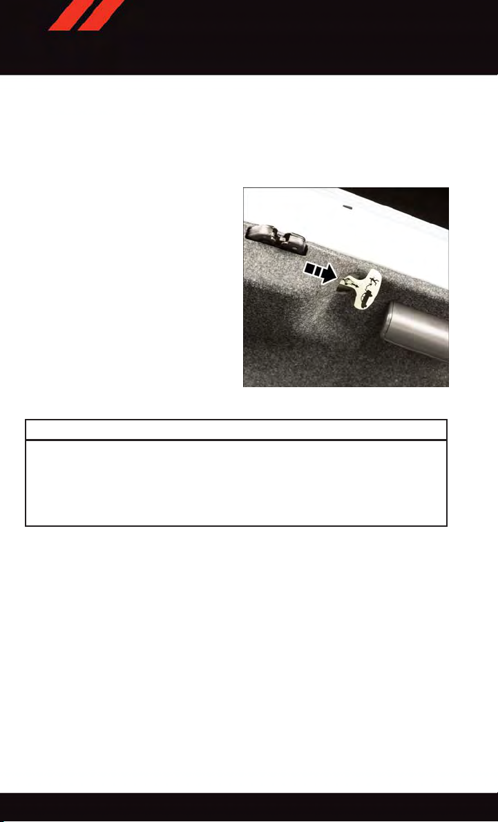
Trunk Emergency Release
As a security measure, a Trunk Internal Emergency Release lever is built into the trunk
latching mechanism. In the event of an individual being locked inside the trunk, the trunk
can be simply opened by pulling on the glow-in-the-dark handle attached to the trunk
latching mechanism.
Internal Emergency Trunk Release
WARNING!
Do not allow children to have access to the trunk, either by climbing into the trunk from
outside, or through the inside of the vehicle. Always close the trunk lid when your
vehicle is unattended. Once in the trunk, young children may not be able to escape,
even if they entered through the rear seat. If trapped in the trunk, children can die from
suffocation or heat stroke.
VEHICLE SECURITY ALARM
The Vehicle Security Alarm monitors the vehicle doors for unauthorized entry and the
Keyless Enter-N-Go™ START/STOP button for unauthorized operation. While the Vehicle
Security Alarm is armed, interior switches for door locks and decklid release are disabled.
If something triggers the alarm, the Vehicle Security Alarm will provide the following
audible and visible signals: the horn will pulse, the park lamps and/or turn signals will
flash, and the Vehicle Security Light in the instrument cluster will flash.
To Arm:
•PushtheKeylessEnter-N-Go™START/STOPbuttonuntiltheDriverInformation
Display (DID) indicates that the vehicle ignition is “OFF .” Push the power door lock
switch while the door is open, push the Key Fob LOCK button, or with one of the Key
Fobs located outside the vehicle and within 5 ft (1.5 m) of the driver's and passenger
front door handles, push the Keyless Enter-N-Go™ LOCK button located on the door
handle.
18
Page 21

GETTING STARTED
NOTE:
After pushing the Keyless Enter-N-Go™ LOCK button, you must wait two seconds before
you can lock or unlock the vehicle via the door handle.
To Disarm:
•PushtheKeyFobUNLOCKbuttonorwithoneoftheKeyFobslocatedoutsidethe
vehicle and within 5 ft (1.5 m) of the driver's and passenger front door handles, grab the
Keyless Enter-N-Go™ door handle and enter the vehicle, then push the Keyless
Enter-N-Go™ ST ART/STOP button (requires at least one valid Key Fob in the vehicle).
SEAT BELT SYSTEMS
Lap/Shoulder Belts
•Allseatingpositionsinyourvehicleareequippedwithlap/shoulderbelts.
•Besureeveryoneinyourvehicleisinaseatandusingaseatbeltproperly.
•Positionthelapbeltsothatitissnugandlieslowacrossyourhips,belowyour
abdomen. To remove slack in the lap belt portion, pull up on the shoulder belt. To loosen
the lap belt if it is too tight, tilt the latch plate and pull on the lap belt. A snug seat belt
reduces the risk of sliding under the seat belt in a collision.
•Positiontheshoulderbeltacrosstheshoulderandchestwithminimal,ifanyslackso
that it is comfortable and not resting on your neck. The retractor will withdraw any slack
in the shoulder belt.
Seat Belt Pretensioner
•Thefrontseatbeltsystemisequippedwithpretensioningdevicesthataredesignedto
remove slack from the seat belt in the event of a collision.
•Adeployedpretensioneroradeployedairbagmustbereplacedimmediately.
WARNING!
•Inacollision,youandyourpassengerscansuffermuchgreaterinjuriesifyouare
not properly buckled up. You can strike the interior of your vehicle or other
passengers, or you can be thrown out of the vehicle. Always be sure you and others
in your vehicle are buckled up properly.
•Ashoulderbeltplacedbehindyouwillnotprotectyoufrominjuryduringacollision.
You are more likely to hi t your head in a collisi on if you do not wear your shoulde r
belt. The lap and shoulder belt are meant to be used together.
•Aseatbeltthatistooloosewillnotprotectyouproperly.Inasuddenstop,youcould
move too far forward, increasing the possibility of injury. Wear your seat belt snugly.
•Afrayedortornseatbeltcouldripapartinacollisionandleaveyouwithno
protection. Inspect the seat belt system periodically, checking for cuts, frays, or
loose parts. Damaged parts must be replaced immediately. Do not disassemble or
modify the system. Seat belt assemblies must be replaced after a collision.
19
Page 22

GETTING STARTED
SUPPLEMENTAL RESTRAINT SYSTEM (SRS) — AIR BAGS
Air Bag System Components
Your v ehicle may be e quipped with the followi ng air bag system compon ents:
•OccupantRestraintController(ORC)
•AirBagWarningLight
•SteeringWheelandColumn
•InstrumentPanel
•KneeImpactBolsters
•AdvancedFrontAirBags
•SupplementalSideAirBags
•SupplementalKneeAirBags
•FrontandSideImpactSensors
•SeatBeltPretenioners
•SeatBeltBuckleSwitch
•SeatTrackPositionSensors
Advanced Front Air Bags
•ThisvehiclehasAdvancedFrontAirBagsforboththedriverandfrontpassengerasa
supplement to the seat belt restraint systems. The Advanced Front Air Bags will not
deploy in every type of collision.
•AdvancedFrontAirBagsaredesignedtoprovideadditionalprotectionbysupplementing the seat belts. Advanced Front Air Bags are not expected to reduce the risk of injury
in rear, side, or rollover collisions.
•TheAdvancedFrontAirBagswillnotdeployinallfrontalcollisions,includingsome
that may produce substantial vehicle damage — for example, some pole collisions,
truck underrides, and angle offset collisions.
•Ontheotherhand,dependingonthetypeandlocationofimpact,AdvancedFrontAir
Bags may deploy in crashes with little vehicle front-end damage but that produce a
severe initial deceleration.
•Becauseairbagsensorsmeasurevehicledecelerationovertime,vehiclespeedand
damage by themselves are not good indicators of whether or not an air bag should have
deployed.
•Seatbeltsarenecessaryforyourprotectioninallcollisions,andalsoareneededtohelp
keep you in position, away from an inflating air bag.
•Theairbagsmustbereadytoinflateforyourprotectioninacollision.TheOccupant
Restraint Controller (ORC) monitors the internal circuits and interconnecting wiring
associated with air bag system electrical components.
20
Page 23

GETTING STARTED
•TheORCturnsontheAirBagWarningLightintheinstrumentpanelforapproximately
four to eight seconds for a self-check when the ignition switch is first turned to the
ON/RUN position. After the self-check, the Air Bag Warning Light will turn off. If the
ORC detects a malfunction in any part of the system, it turns on the Air Bag Warning
Light, either momentarily or continuously. A single chime will sound to alert you if the
light comes on again after initial startup.
The ORC monitors the readiness of the electronic parts of the air bag system whenever the
•
ignition switch is in the START or ON/RUN position. If the ignition switch is in the OFF
position or in the ACC position, the air bag system is not on and the air bags will not inflate.
•
If the Air Bag Warning Light in the instrument panel is not on during the four to eight
seconds when the ignition switch is first turned to the ON/RUN position, stays on, or turns
on while driving, have the vehicle serviced by an authorized service center immediately.
NOTE:
If the speedometer, tachometer, or any engine related gauges are not working, the
Occupant Restraint Controller (ORC) may also be disabled. In this condition the air bags
may not be ready to inflate for your protection. Have an authorized dealer service the air
bag system immediately.
•Afteranycollision,thevehicleshouldbetakentoanauthorizeddealerimmediately.
•Donotdriveyourvehicleaftertheairbagshavedeployed.Ifyouareinvolvedinanother
collision, the air bags will not be in place to protect you.
•Ifitisnecessarytomodifytheairbagsystemforpersonswithdisabilities,contactyour
authorized dealer.
•RefertotheOwner'sManualontheDVDforfurtherdetailsregardingtheSupplemental
Restraint System (SRS).
Supplemental Knee Air Bags
This vehicle is equipped with a Supplemental Driver Knee Air Bag mounted in the
instrument panel below the steering column. The Supplemental Driver Knee Air Bag
provides enhanced protection during a frontal impact by working together with the seat
belts, pretensioners, and Advanced Front Air Bags.
WARNING!
•Relyingontheairbagsalonecouldleadtomoresevereinjuriesinacollision.The
air bags work with your seat belt to restrain you properly. In some collisions, the air
bags won't deploy at all. Always wear your seat belts even though you have air bags.
•BeingtooclosetothesteeringwheelorinstrumentpanelduringAdvancedFrontAir
Bag deployment could cause serious injury, including death. Air bags need room to
inflate. Sit back, comfortably extending your arms to reach the steering wheel or
instrument panel.
•Noobjectsshouldbeplacedoverorneartheairbagontheinstrumentpanelor
steering wheel because any such objects could cause harm if the vehicle is in a
collision severe enough to cause the air bag to inflate.
21
Page 24

GETTING STARTED
Supplemental Side Air Bags
•ThisvehicleisequippedwithSupplementalSeat-MountedSideAirBags(SABs)
located in the outboard side of the front seats. The SABs are marked with a SRS
AIRBAG or AIRBAG label sewn into the outboard side of the seats.
•ThisvehicleisequippedwithSupplementalSideAirBagInflatableCurtains(SABICs)
located above the side windows. The trim covering the SABICs is labeled SRS AIRBAG
or AIRBAG. The SABICs may help reduce the risk of partial or complete ejection of
vehicle occupants through side windows in certain side impact events.
•TheSABICsandSABs(“SideAirBags”)aredesignedtoactivateincertainside
impacts and certain rollover events. The Occupant Restraint Controller (“ORC”)
determines whether the deployment of the Side Air Bags in a particular side impact or
rollover event is appropriate, based on the severity and type of collision. Vehicle damage
by itself is not a good indicator of whether or not Side Air Bags should have deployed.
WARNING!
•SideAirBagsneedroomtoinflate.Donotleanagainstthedoororwindow.Sit
upright in the center of the seat.
•BeingtooclosetotheSideAirBagsduringdeploymentcouldcauseyoutobe
severely injured or killed.
•RelyingontheSideAirBagsalonecouldleadtomoresevereinjuriesinacollision.
The Side Air Bags work with your seat belt to restrain you properly. In some
collisions, Side Air Bags won’t deploy at all. Always wear your seat belt even though
you have Side Air Bags.
•
This vehicle is equipped with left and right Supplemental Side Air Bag Inflatable
Curtains (SABICs). Do not stack luggage or other cargo up high enough to block the
deployment of the SABICs. The trim covering above the side windows where the SABIC
and its deployment path are located should remain free from any obstructions.
•ThisvehicleisequippedwithSABICs.InorderfortheSABICstoworkasintended,
do not install any accessory items in your vehicle which could alter the roof. Do not
add an aftermarket sunroof to your vehicle. Do not add roof racks that require
permanent attachments (bolts or screws) for installation on the vehicle roof. Do not
drill into the roof of the vehicle for any reason.
•DonotuseaccessoryseatcoversorplaceobjectsbetweenyouandtheSideAir
Bags; the performance could be adversely affected and/or objects could be pushed
into you, causing serious injury.
22
Page 25
GETTING STARTED
CHILD RESTRAINTS
Children 12 years or younger should ride properly buckled up in a rear seat, if available.
According to crash statistics, children are safer when properly restrained in the rear seats
rather than in the front.
Every state in the United States and all Canadian provinces require that small children
ride in proper restraint systems. This is the law, and you can be prosecuted for ignoring it.
NOTE:
•Foradditionalinformation,refertowww.Seatcheck.orgorcall1-866-SEATCHECK.
•CanadianresidentsshouldrefertoTransportCanada’swebsiteforadditionalinformation: http://www.tc.gc.ca/eng/motorvehiclesafety/safedrivers-childsafety-index-53.htm
LATCH – Lower Anchors And Tethers For CHildren
•YourvehicleisequippedwiththechildrestraintanchoragesystemcalledLATCH,
which stands for Lower Anchors and Tethers for CHildren.
•Allrearseatingpositionshaveloweranchorsandtoptetheranchors.
LATCH System Weight Limit
You may use the LATC H anch orage syste m unti l th e comb ined weight of the c hild and t he
child restraint is 65 lbs (29.5 kg). Use the seat belt and tether anchor instead of the
LA TCH system once the combined weight is more than 65 lbs (29.5 kg).
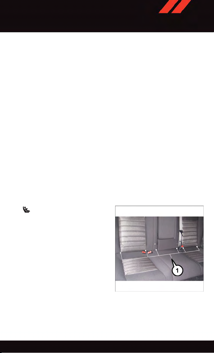
Locating LATCH Anchorages
The lower anchorages are round bars
that are found at the rear of the seat cushion
where it meets the seatback, below the
anchorage symbols on the seatback. They
are just visible when you lean into the rear
seat to install the child restraint. You will
easily feel them if you run your finger along
the gap between the seatback and seat
cushion.
LATCH Lower Anchors
23
Page 26
GETTING STARTED
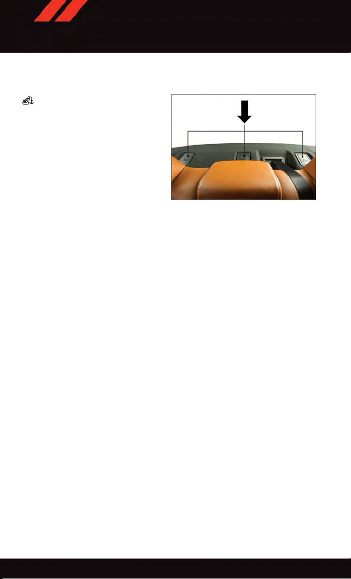
Locating Tether Anchorages
In addition, there are tether strap
anchorages behind each rear seating position located in the panel between the rear
seatback and the rear window. These tether
strap anchorages are under a plastic cover
with the tether anchorage symbol on it.
Center Seat LATCH
If a child restraint installed in the center
position blocks the seat belt webbing or
buckle for the outboard position, do not use
that outboard position. If a child seat in the
center position blocks the outboard LATCH anchors or seat belt, do not install a child seat
in that outboard position.
Installing The Child Restraint Using The LATCH Lower Anchors
NOTE:
Never “share” a LATCH anchorage with two or more child restraints.
1. Loosen the adjusters on the lower straps and on the tether strap of the child seat so that
you can more easily attach the hooks or connectors to the vehicle anchorages.
2. Attach the lower hooks or connectors of the child restraint to the lower anchorages in
the selected seating position.
3. If the child restraint has a tether strap, connect it to the top tether anchorage. See
below for directions to attach a tether anchor.
4. Tighten all of the straps as you push the child restraint rearward and downward into the
seat. Remove slack in the straps according to the child restraint manufacturer’s
instructions.
5. Test that the child restraint is installed tightly by pulling back and forth on the child
seat at the belt path. It should not move more than 1 inch (25.4 mm) in any direction.
Tether Anchorages
Installing The Child Restraint Using The Vehicle Seat Belts
The seat belts in the passenger seating positions are equipped with a Switchable
Automatic Locking Retractor (ALR) that is designed to keep the lap portion of the seat belt
tight around the child restraint. Any seat belt system will loosen with time, so check the
belt occasionally, and pull it tight if necessary.
Tether Anchorage Weight Limit
Always use the tether anchor when using the seat belt to install a forward facing child
restraint, up to the recommended weight limit of the child restraint.
24
Page 27

GETTING STARTED
To Install A Child Seat Using An ALR:
1. Pull enough of the seat belt webbing from the retractor to pass it through the belt path
of the child restraint. Do not twist the belt webbing in the belt path.
2. Slide the latch plate into the buckle until you hear a “click.”
3. Pull on the webbing to make the lap portion tight against the child seat.
4. To lock the seat belt, pull down on the shoulder part of the belt until you have pulled
all the seat belt webbing out of the retractor. Then, allow the webbing to retract back
into the retractor. As the webbing retracts, you will hear a clicking sound. This means
the seat belt is now in the Automatic Locking mode.
5. Try to pull the webbing out of the retractor. If it is locked, you should not be able to pull
out any webbing. If the retractor is not locked, repeat the last step.
6. Finally, pull up on any extra webbing to tighten the lap portion around the child
restraint while you push the child restraint rearward and downward into the vehicle
seat.
7. If the child restraint has a top tether strap and the seating position has a top tether
anchorage, connect the tether strap to the anchorage and tighten the tether strap. See
below for directions to attach a tether anchor.
8. Test that the child restraint is installed tightly by pulling back and forth on the child
seat at the belt path. It should not move more than 1 inch (25.4 mm) in any direction.
Installing The Top Tether Strap (With Either Lower Anchors Or Vehicle Seat Belt):
When installing a forward-facing child restraint, always secure the top tether strap, up to
the tether anchor weight limit, whether the child restraint is installed with the lower
anchors or the vehicle seat belt.
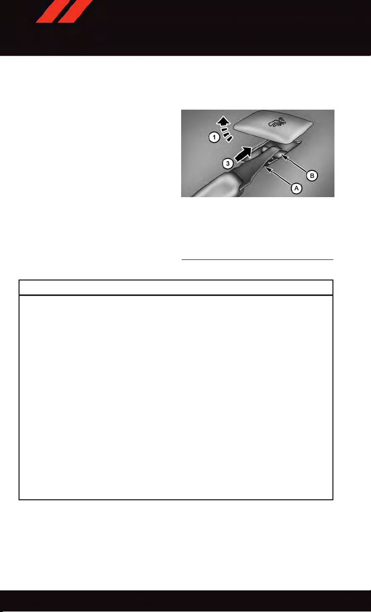
Tether Strap Installation
1. Rotate or lift the cover to access the anchor directly behind the seat where you are
placing the child restraint.
2. Route the tether strap to provide the most direct path for the strap between the anchor
and the child seat.
3. If your vehicle is equipped with adjustable rear head restraints, raise the head
restraint, and where possible, route the tether strap under the head restraint and
between the two posts. If not possible, lower the head restraint and pass the tether
strap around the outboard side of the head restraint.
25
Page 28
GETTING STARTED
4. Attach the tether strap hook of the child restraint to the top tether anchorage and
remove slack in the tether strap according to the child restraint manufacturer’s
instructions.
Tether Strap Mounting
1—Cover
3—AttachingStrap
A—TetherStrapHook
B—TetherAnchor
WARNING!
•Inacollision,anunrestrainedchild,evenatinybaby,canbecomeaprojectile
inside the vehicle. The force required to hold even an infant on your lap could
become so great that you could not hold the child, no matter how strong you are.
The child and others could be severely injured or killed. Any child riding in your
vehicle should be in a proper restraint for the child's size.
•Rearward-facingchildseatsmustneverbeusedinthefrontseatofavehiclewith
afrontpassengerairbag.Anairbagdeploymentcouldcausesevereinjuryordeath
to infants in this position.
•Onlyusearearward-facingchildrestraintinavehiclewitharearseat.
•ImproperinstallationofachildrestrainttotheLATCHanchoragescanleadto
failure of an infant or child restraint. The child could be severely injured or killed.
Follow the manufacturer’s directions exactly when installing an infant or child
restraint.
•Anincorrectlyanchoredtetherstrapcouldleadtoincreasedheadmotionand
possible injury to the child. Use only the anchor positions directly behind the child
seat to secure a child restraint top tether strap.
•Ifyourvehicleisequippedwithasplitrearseat,makesurethetetherstrapdoesnot
slip into the opening between the seatbacks as you remove slack in the strap.
26
Page 29
GETTING STARTED
HEAD RESTRAINTS
Head restraints are designed to reduce the risk of injury by restricting head movement in
the event of a rear impact. Head restraints should be adjusted so that the top of the head
restraint is located above the top of your ear.
WARNING!
The head restraints for all occupants must be properly adjusted prior to operating the
vehicle or occupying a seat. Head restraints should never be adjusted while the vehicle
is in motion. Driving a vehicle with the head restraints improperly adjusted or removed
could cause serious injury or death in the event of a collision.
Reactive Head Restraints — Front Seats
The front driver and passenger seats are equipped with Reactive Head Restraints (RHR).
In the event of a rear impact the RHRs will automatically extend forward minimizing the
gap between the back of the occupants head and the RHR.
The RHRs will automatically return to their normal position following a rear impact. If the
RHRs do not return to their normal position see your authorized dealer immediately.
To ra ise t he h ead r est rai n t, p ull u pwa r d o n the h ead res t rai nt. To low er t h e he ad r e str ain t ,
press the adjustment button, located at the base of the head restraint, and push
downward on the head restraint.
NOTE:
To re m ove t he h e ad r est r ain t , ra i se i t as f a r as i t can g o th e n pu s h th e rel e ase b utt on a n d
the adjustment button at the base of each post while pulling the head restraint up. To
reinstall the head restraint, put the head restraint posts into the holes and push
downward. Then adjust the head restraint to the appropriate height.
WARNING!
•Alooseheadrestraintthrownforwardinacollisionorhardstopcouldcauseserious
injury or death to occupants of the vehicle. Always securely stow removed head
restraints in a location outside the occupant compartment.
•ALLtheheadrestraintsMUSTbereinstalledinthevehicletoproperlyprotectthe
occupants. Follow the re-installation instructions above prior to operating the
vehicle or occupying a seat.
•DonotplaceitemsoverthetopoftheReactiveHeadRestraint,suchascoats,seat
covers or portable DVD players. These items may interfere with the operation of the
Reactive Head Restraint in the event of a collision and could result in serious injury
or death.
27
Page 30
GETTING STARTED
Rear Head Restraints
The center head restraint has two adjustable positions, up or down. When the center seat
is being occupied the head restraint should be in the raised position. When there are no
occupants in the center seat the head restraint can be lowered for maximum visibility for
the driver.
To ra ise t he h ead r est rai n t, p ull u pwa r d o n the h ead res t rai nt. To low er t h e he ad r e str ain t ,
press the adjustment button, located at the base of the head restraint, and push
downward on the head restraint.
NOTE:
•Theheadrestraintshouldonlyberemovedbyqualifiedtechnicians,forservice
purposes only. If the center rear head restraints requires removal, see your authorized
dealer.
•Theoutboardheadrestraintsarenotadjustable.
FRONT SEATS
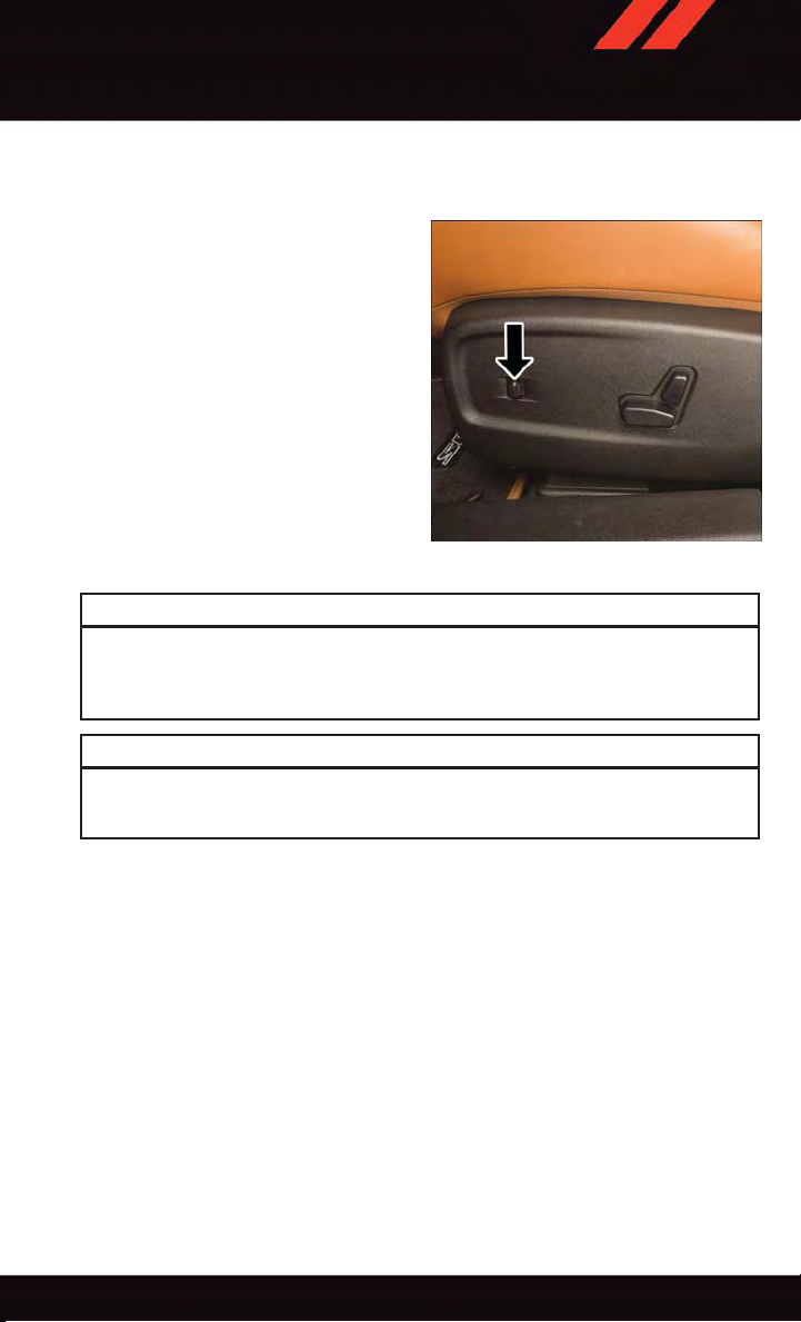
Power Seats
The power seat switches are located on the
outboard side of the front seat cushions.
The power seat switch controls forward/
back, up/down and tilt adjustment. The
recline switch controls the angle of the
seatback.
•
Press the switch forward or rearward and
the seatback will move in either direction.
28
Power Seat Switches
1—ReclineSwitch
2—PowerSeatSwitch
Page 31

GETTING STARTED
Power Lumbar
•Pushtheswitchforwardtoincreasethe
lumbar support. Push the switch rearward to decrease the lumbar support.
•Pushingupwardordownwardonthe
switch will raise and lower the position of
the support.
Memory Seat
The memory seat feature allows you to set
two different driver seating positions (excluding lumbar position), outside mirrors,
radio station preset settings and tilt/
telescoping steering column position (if
equipped). The memory seat buttons are
located on the driver's door panel.
To set a me m ory p o sit ion:
1. Cycle the vehicles ignition to the ON
position.
2. Adjust all memory profile settings.
3. Press and release the S (SET) button.
4. Press and release the 1 or 2 button
within five seconds.
NOTE:
Before programming your RKE transmitters
you must select the feature through the
Uconnect
Settings ” in “Understanding Your Instrument Panel” in the Owner's Manual on the
DVD for further details.
To pro g ram a K e y Fob t o t he me m ory p o sit ion :
1. Cycle the vehicles ignition to the OFF position.
2. Select the desired memory profile 1 or 2.
3. Press and release the S (SET) button on the memory switch, then within five seconds
4. Press and release the LOCK button on the RKE transmitter within 10 seconds.
•Torecallthesavedpositions,press1or2onthememoryswitchorpressUNLOCKon
®
system. Refer to “Uconnect
press and release the 1 or 2 button accordingly.
the programmed RKE transmitter.
®
Power Lumbar Switch
Driver’s Memory Buttons
29
Page 32

GETTING STARTED
Easy Entry/Exit Feature
The memory seat has an Easy Entry/Exit feature. This feature provides automatic driver
seat positioning to enhance driver mobility when entering and exiting the vehicle.
NOTE:
The Easy Entry/Exit feature is not enabled when the vehicle is delivered from the factory.
To ena ble ( or la t er d i sab le) t his f eat u re y o u mus t sel e ct “ E asy E xit S eat s ” in “ E ngi ne Of f
Options” through the programmable features in the Uconnect
®
•Referto“Uconnect
Guide.
•Forfurtherdetailsreferto“Uconnect
Panel” in the Owner's Manual on the DVD.
Customer Programmable Features” in “Electronics” of this User
®
Settings” in “Understanding Your Instrument
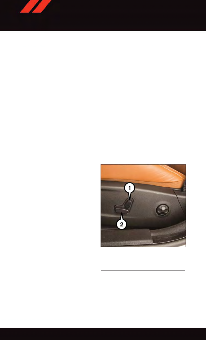
Manual Seat Adjustments
Forward/Rearward
•Liftupontheadjustingbarlocatedat
the front of the seat near the floor and
release it when the seat is at the desired
position. Then, using body pressure,
move forward and backward on the seat
to be sure that the seat adjusters have
latched.
Recliner
•Leanforwardintheseatandliftthe
recliner lever , then lean back to the desired position and release the lever.
•Liftthelevertoreturntheseatbacktoan
upright position.
1—ReclinerLever
2—AdjustmentBar
®
system.
Manual Seat Adjustment
CAUTION!
Do not place any article under a power seat or impede its ability to move as it may cause
damage to the seat controls. Seat travel may become limited if movement is stopped
by an obstruction in the seat’s path.
30
Page 33

GETTING STARTED
WARNING!
•Adjustingaseatwhilethevehicleismovingisdangerous.Thesuddenmovementof
the seat could cause you to lose control. The seat belt might not be properly
adjusted, and you could be severely injured or killed. Only adjust a seat while the
vehicle is parked.
•Donotridewiththeseatbackreclinedsothattheseatbeltisnolongerresting
against your chest. In a collision, you could slide under the seat belt and be severely
injured or killed. Use the recliner only when the vehicle is parked.
REAR SEATS
Folding Rear Seatback
•Pullontheloops,locatedneartheouter
top of the seatbacks, to fold down either
or both seatbacks. These loops can be
tucked away when not in use.
•Whentheseatbackisraisedtotheupright position, make sure it is latched by
strongly pulling on the top of the seatback above the seat loop.
Rear Seat Loop
WARNING!
•Becertainthattheseatbackissecurelylockedintoposition.Iftheseatbackisnot
securely locked into position, the seat will not provide the proper stability for child
seats and/or passengers. An improperly latched seat could cause you and others to
severely injured or killed.
•Thecargoareaintherearofthevehicle(withtherearseatbacksinthelocked-upor
folded-down position) should not be used as a play area by children when the
vehicle is in motion. They could be severely injured or killed in a collision. Children
should be seated and using the proper restraint system.
31
Page 34

GETTING STARTED
HEATED/VENTILATED SEATS
Heated Seats
On some models, the front and rear seats may be equipped with heaters in both the seat
cushions and seatbacks.
The front driver and passenger heated seats are operated using the Uconnect
WARNING!
•Personswhoareunabletofeelpaintotheskinbecauseofadvancedage,chronic
illness, diabetes, spinal cord injury, medication, alcohol use, exhaustion or other
physical condition must exercise care when using the seat heater. It may cause
burns even at low temperatures, especially if used for long periods of time.
•Donotplaceanythingontheseatorseatbackthatinsulatesagainstheat,suchas
ablanketorcushion.Thismaycausetheseatheatertooverheat.Sittinginaseat
that has been overheated could cause serious burns due to the increased surface
temperature of the seat.
Front Heated Seats
The front heated seats control buttons are located within the climate or controls screen of
the touchscreen.
You ca n choose fr om HI , LO or OFF h eat sett ings. The indi cator li ghts in each switch
indicate the level of heat in use. T wo indicator lights will illuminate for HI, one for LO and
none for OFF.
•Presstheheatedseatbutton
•Presstheheatedseatbutton
•Presstheheatedseatbutton
If the HI-level setting is selected, the system will automatically switch to LO-level after
approximately 60 minutes of continuous operation. At that time, the display will change
from HI to LO, indicating the change. The LO-level setting will turn OFF automatically
after approximately 45 minutes.
NOTE:
•Onceaheatsettingisselected,heatwillbefeltwithintwotofiveminutes.
•Theenginemustberunningfortheheatedseatstooperate.
Vehicles Equipped With Remote Start
On models that are equipped with remote start, the heated seats can be programed to
come on during a remote start.
This feature can be programmed through the Uconnect
Settings” in “Understanding Your Instrument Panel” in the Owner's Manual on the DVD.
32
once to turn the HI setting ON.
asecondtimetoturntheLOsettingON.
athirdtimetoturntheheatingelementsOFF.
®
system. Refer to “Uconnect
®
System.
®
Page 35

GETTING STARTED
Rear Heated Seats
On some models, the two outboard seats are equipped with heated seats. The heated seat
switches for these seats are located on the rear of the center console. There are two heated
seat switches
You ca n choo se fr om HI , LO or OFF heat se ttings. The indicato r ligh ts in ea ch sw itch
indicate the level of heat in use. Two indicator lights will illuminate for HI, one for LO and
none for OFF.
•Presstheheatedseatbutton
•Presstheheatedseatbutton
•Presstheheatedseatbutton
NOTE:
•Onceaheatsettingisselected,heatwillbefeltwithintwotofiveminutes.
•Theenginemustberunningfortheheatedseatstooperate.
When the HI-level setting is selected, the heater will provide a boosted heat level during
the first four minutes of operation. Then, the heat output will drop to the normal HI-level.
If the HI-level setting is selected, the system will automatically switch to LO-level after
approximately 60 minutes of continuous operation. At that time, the number of illuminated LEDs changes from two to one, indicating the change. The LO-level setting will turn
OFF automatically after approximately 45 minutes.
Front Ventilated Seats
Located in the seat cushion and seat back are small fans that draw the air from the
passenger compartment and move air through fine perforations in the seat cover to help
keep the driver and front passenger cooler in higher ambient temperatures. The fans
operate at two speeds, HI and LO.
The front ventilated seats control buttons are located within the Uconnect
can gain access to the control buttons through the climate screen or the controls screen.
•Presstheventilatedseatbutton
•Presstheventilatedseatbutton
•Presstheventilatedseatbutton
NOTE:
The engine must be running for the ventilated seats to operate.
Vehicles Equipped With Remote Start
On models that are equipped with remote start, the ventilated seats can be programed to
come on during a remote start.
This feature can be programmed through the Uconnect
Settings” in “Understanding Your Instrument Panel” in the Owner's Manual on the DVD.
that allow the rear passengers to operate the seats independently.
once to select HI-level heating.
asecondtimetoselectLO-levelheating.
athirdtimetoturntheheatingelementsOFF.
®
system. You
once to choose HI.
asecondtimetochooseLO.
athirdtimetoturntheventilatedseatOFF.
®
system. Refer to “Uconnect
®
33
Page 36
GETTING STARTED
HEATED STEERING WHEEL
The steering wheel contains a heating element that heats the steering wheel to one
temperature setting.
The heated steering wheel control button is located within the Uconnect
gain access to the control buttons through the climate screen or the controls screen.
•Presstheheatedsteeringwheelbutton
•Presstheheatedsteeringwheelbutton
OFF.
Once the heated steering wheel has been turned on, it will operate for up to 80 minutes
before automatically shutting off. The heated steering wheel can shut off early or may not
turn on when the steering wheel is already warm.
Vehicle Equipped With Remote Start
On models that are equipped with remote start, this feature can be programmed to come
on during a remote start through the Uconnect
in “Understanding Your Instrument Panel” in the Owner's Manual on the DVD.
once to turn the heating element ON.
asecondtimetoturntheheatingelement
®
system. Refer to “Uconnect®Settings”
WARNING!
•Personswhoareunabletofeelpaintotheskinbecauseofadvancedage,chronic
illness, diabetes, spinal cord injury , medication, alcohol use, exhaustion, or other
physical conditions must exercise care when using the steering wheel heater. It may
cause burns even at low temperatures, especially if used for long periods.
•Donotplaceanythingonthesteeringwheelthatinsulatesagainstheat,suchasa
blanket or steering wheel covers of any type and material. This may cause the
steering wheel heater to overheat.
®
system. You can
34
Page 37
GETTING STARTED
ADJUSTABLE PEDALS
The adjustable pedal switch is located on
the front side of the driver’s seat cushion
side shield.
•Presstheswitchforwardtomovethe
pedals forward (toward the front of the
vehicle).
•Presstheswitchrearwardtomovethe
pedals rearward (toward the driver).
NOTE:
The pedals cannot be adjusted when the
vehicle is in REVERSE or when the Electronic Speed Control is set.
Adjustable Pedals Switch
CAUTION!
Do not place any article under the adjustable pedals or impede its ability to move, as
it may cause damage to the pedal controls. Pedal travel may become limited if
movement is stopped by an obstruction in the adjustable pedal's path.
WARNING!
Do not adjust the pedals while the vehicle is moving. Y ou could lose control and have
acollision.Alwaysadjustthepedalswhilethevehicleisparked.
35
Page 38

GETTING STARTED
TILT/TELESCOPING STEERING COLUMN
Manual Tilt/Telescoping Steering Column
•Thetilt/telescopingcontrolhandleislocated below the steering wheel at the end
of the steering column.
•Tounlockthesteeringcolumn,pushthe
lever downward (toward the floor).
•Totiltthesteeringcolumn,movethe
steering wheel upward or downward as
desired.
•Tolengthenorshortenthesteeringcolumn, pull the steering wheel outward or
push it inward as desired.
•Tolockthesteeringcolumninposition,
push the lever upward until fully
engaged.
Manual Tilt/Telescoping Control Handle
36
Page 39

GETTING STARTED
Power Tilt/Telescoping Steering Column
•Thepowertilt/telescopingsteeringcontrol is located below the turn signal/
wiper/washer/high beam lever on the
steering column.
•Totiltthesteeringcolumn,movethe
power tilt/telescoping control up or down
as desired. To lengthen or shorten the
steering column, pull the control toward
you or push the control away from you as
desired.
Power Tilt/Telescoping Steering Control
WARNING!
•Donotadjustthesteeringwheelwhiledriving.Thetilt/telescopingadjustmentmust
be locked while driving. Adjusting the steering wheel while driving or driving
without the tilt/telescoping adjustment locked could cause the driver to lose control
of the vehicle. Failure to follow this warning may result in you and others being
severely injured or killed.
•Movingthesteeringcolumnwhilethevehicleismovingisdangerous.Withouta
stable steering column, you could lose control of the vehicle and have a collision.
Adjust the column only while the vehicle is stopped.
37
Page 40

OPERATING YOUR VEHICLE
ENGINE BREAK-IN RECOMMENDATIONS
For vehicles equipped with the 3.6L or 5.7L use the following engine break-in recommendations:
Alongbreak-inperiodisnotrequiredforthedrivetrain(engine,transmission,clutch,and
rear axle) in your new vehicle.
Drive moderately during the first 300 mi (500 km). After the initial 60 mi (100 km),
speeds up to 50 or 55 mph (80 or 90 km/h) are desirable.
While cruising, brief full-throttle acceleration within the limits of local traffic laws
contributes to a good break-in. However, wide-open throttle acceleration in low gear can
be detrimental and should be avoided.
The engine oil, transmission fluid, and axle lubricant installed at the factory is high-quality
and energy-conserving. Oil, fluid, and lubricant changes should be consistent with
anticipated climate and conditions under which vehicle operations will occur. For the
recommended viscosity and quality grades, refer to “Maintenance Procedures” in “Maintaining Your Vehicle”.
CAUTION!
Never use Non-Detergent Oil or Straight Mineral Oil in the engine or damage may
result.
NOTE:
Anewenginemayconsumesomeoilduringitsfirstfewthousandmiles(kilometers)of
operation. This should be considered a normal part of the break-in and not interpreted as
an indication of difficulty. Please check your oil level with the engine oil indicator often
during the break in period. Add oil as required.
For vehicles equipped with the 6.4L use the following engine break-in recommendations:
Despite modern technology and World Class manufacturing methods, the moving parts of
the vehicle must still wear in with each other.This wearing in occurs mainly during the first
500 miles (805 km) and continues through the first oil change interval.
It is recommended for the operator to observe the following driving behaviors during the
new vehicle break-in period:
0to100miles(0to161km):
•Donotallowtheenginetooperateatidleforanextendedperiodoftime.
•Depresstheacceleratorpedalslowlyandnotmorethanhalfwaytoavoidrapid
acceleration.
•Avoidaggressivebraking.
•Drivewiththeenginespeedlessthan3,500RPM.
•Maintainvehiclespeedbelow55mph(88km/h)andobservelocalspeedlimits.
38
Page 41

OPERATING YOUR VEHICLE
100 to 300 miles (161 to 483 km):
•Depresstheacceleratorpedalslowlyandnotmorethanhalfwaytoavoidrapid
acceleration in lower gears (1st to 3rd gears).
•Avoidaggressivebraking.
•Drivewiththeenginespeedlessthan5,000RPM.
•Maintainvehiclespeedbelow70mph(112km/h)andobservelocalspeedlimits.
300 to 500 miles (483 to 805 km):
•Exercisethefullenginerpmrange,shiftingmanually(paddlesorgearshift)athigher
rpms when possible.
•Donotperformsustainedoperationwiththeacceleratorpedalatwideopenthrottle.
•Maintainvehiclespeedbelow85mph(136km/h)andobservelocalspeedlimits.
For the first 1500 mi (2414 km):
•Donotparticipateintrackevents,sportdrivingschools,orsimilaractivitiesduringthe
first 1500 mi (2414 km).
NOTE:
Check engine oil with every refueling and add if necessary. Oil and fuel consumption may
be higher through the first oil change interval.
SRT Engine Break-In Recommendations
SRT Engine Break-In Recommendations: The following tips will be helpful in obtaining
optimum performance and maximum durability for your new SRT Vehicle.
Despite modern technology and World Class manufacturing methods, the moving parts of
the vehicle must still wear in with each other.This wearing in occurs mainly during the first
500 miles (805 km) and continues through the first oil change interval.
It is recommended for the operator to observe the following driving behaviors during the
new vehicle break-in period:
0to100miles(0to161km):
•Donotallowtheenginetooperateatidleforanextendedperiodoftime.
•Depresstheacceleratorpedalslowlyandnotmorethanhalfwaytoavoidrapid
acceleration.
•Avoidaggressivebraking.
•Drivewiththeenginespeedlessthan3,500RPM.
•Maintainvehiclespeedbelow55mph(88km/h)andobservelocalspeedlimits.
39
Page 42

OPERATING YOUR VEHICLE
100 to 300 miles (161 to 483 km):
•Depresstheacceleratorpedalslowlyandnotmorethanhalfwaytoavoidrapid
acceleration in lower gears (1st to 3rd gears).
•Avoidaggressivebraking.
•Drivewiththeenginespeedlessthan5,000RPM.
•Maintainvehiclespeedbelow70mph(112km/h)andobservelocalspeedlimits.
300 to 500 miles (483 to 805 km):
•Exercisethefullenginerpmrange,shiftingmanually(paddlesorgearshift)athigher
rpms when possible.
•Donotperformsustainedoperationwiththeacceleratorpedalatwideopenthrottle.
•Maintainvehiclespeedbelow85mph(136km/h)andobservelocalspeedlimits.
For the first 1500 mi (2414 km):
•Donotparticipateintrackevents,sportdrivingschools,orsimilaractivitiesduringthe
first 1500 mi (2414 km).
NOTE:
Check engine oil with every refueling and add if necessary. Oil and fuel consumption may
be higher through the first oil change interval.
40
Page 43
OPERATING YOUR VEHICLE
TURN SIGNAL/WIPER/WASHER/HIGH BEAM LEVER
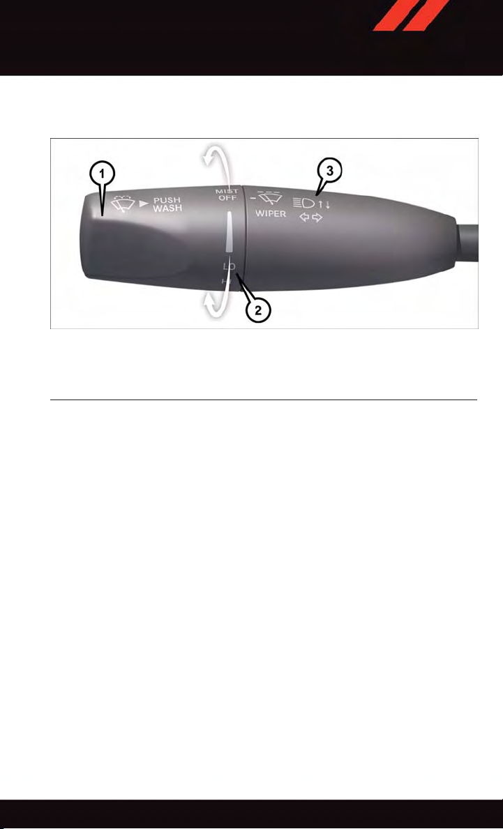
Multifunction Lever
1—PushForWasher
2—RotateDownwardForMist
3—PushLeverForHighBeams
Turn Signal/Lane Change Assist
Tap t h e le v er u p or d o wn o nce a nd th e tur n sig nal ( righ t or l eft ) wil l fla s h th r ee t i mes a nd
automatically turn off.
Front Wipers
Intermittent, Low And High Operation
Rotate the end of the lever to the first detent position for one of four intermittent settings,
the second detent for low wiper operation and the third detent for high wiper operation.
Mist
Rotate the end of the lever rearward when a single wipe is desired.
NOTE:
The mist feature does not activate the washer pump; therefore, no washer fluid will be
sprayed on the windshield. The wash function must be activated in order to spray the
windshield with washer fluid.
Washer Operation
Push the end of the lever inward and hold for as long as spray is desired.
41
Page 44

OPERATING YOUR VEHICLE
Rain Sensing Wipers
This feature senses moisture on the vehicle's windshield and automatically activates the
wipers for the driver when the switch is in the intermittent position. Rotate the end of the
lever to one of four settings to activate this feature and adjust sensitivity.
Rain Sensing can be turned on and off using the Uconnect
Manual on the DVD for further details.
High Beam Operation
Push the lever forward to activate the high beams. Pull the lever toward you for flash to
pass.
NOTE:
For safe driving, turn off the high beams when oncoming traffic is present to prevent
headlight glare and as a courtesy to other motorists.
HEADLIGHT SWITCH
Automatic Headlights/Parking Lights/Headlights
•Rotatetheheadlightswitch,locatedon
the instrument panel to the left of the
steering wheel, to the first detent from
the off position for parking light
and to the second detent for headlight
.
•Withtheparkinglightsorlowbeam
headlights on, press the headlight switch
for front fog lights. Pressing the switch a
second time will deactivate the front fog
lights. Turning the headlight switch off
will also deactivate the front fog lights.
•Rotatetheheadlightswitchto“AUTO”
for AUTO headlights.
•WhensettoAUTO,thesystemautomatically turns the headlights on or off based on ambient light levels.
1—AutomaticHeadlights
2—RotateHeadlightSwitch
3—RotateDimmer
4—RotateAmbient
®
System, refer to the Owner's
Headlight Switch
Automatic High Beams
The Automatic High Beams system provides increased forward lighting at night by
automating high beam control through the use of a digital camera mounted above the
inside rearview mirror. This camera detects vehicle specific light and automatically
switches from high beams to low beams until the approaching vehicle is out of view. This
feature is programmable through the Uconnect
in “Understanding Your Instrument Panel” in the Owner's Manual on the DVD for further
details.
®
system. Refer to “Uconnect®Settings”
42
Page 45

OPERATING YOUR VEHICLE
Instrument Panel Dimmer
•Rotatethedimmercontroltotheextremebottompositiontofullydimtheinstrument
panel lights and prevent the interior lights from illuminating when a door is opened.
•Rotatethedimmercontroluptoincreasethebrightnessoftheinstrumentpaneland
cupholders when the parking lights or headlights are on.
•Rotatethedimmercontroluptothenextdetentpositiontofullybrightentheodometer
and radio when the parking lights or headlights are on.
•Rotatethedimmercontroluptothelastdetentpositiontoturnontheinteriorlighting.
•Ifyourvehicleisequippedwithatouchscreen,thedimmingisprogrammablethrough
the Uconnect
ment Panel” in the Owner's Manual on the DVD for further details.
Ambient Light Dimmer
•Rotatetheambientlightcontrolupordowntoincreaseordecreasethebrightnessof
the release handle, map pocket (if equipped), overhead and floor lighting when the
parking lights or headlights are on.
•Rotatetoextremebottompositiontoturnoff.
ELECTRONIC SPEED CONTROL
The Electronic Speed Control switches are located on the right side of the steering wheel.
Cruise ON/OFF
•PushtheON/OFFbutton
the Electronic Speed Control.
CRUISE CONTROL READY will appear in
the Driver Information Display (DID) to indicate the Electronic Speed Control is on.
•PushtheON/OFFbutton
time to turn the system off.
CRUISE CONTROL OFF will appear in the
Driver Information Display (DID) to indicate
the Electronic Speed Control is off.
®
system. Refer to “Uconnect®Settings” in “Understanding Your Instru-
to activate
asecond
Electronic Speed Control Switches
1—PushCancel
2—PushSet+/Accel
3—PushResume
4—PushOn/Off
5—PushSet-/Decel
43
Page 46

OPERATING YOUR VEHICLE
SET
•WiththeElectronicSpeedControlon,pushandreleasetheSET+orSET-buttontoset
adesiredspeed.
Once a speed has been set a message CRUISE CONTROL SET TO MPH/KM will appear
indicating what speed was set. An indicator CRUISE will also appear and stay on in the
Driver Information Display (DID) when the speed is set.
Accel/Decel
To Increase Speed
•WhentheElectronicSpeedControlisset,youcanincreasespeedbypushingtheSET
+ button.
The drivers preferred units can be selected through the instrument panel settings if
equipped. Refer to “Understanding Your Instrument Panel” in the Owner’s Manual on the
DVD for more information. The speed increment shown is dependant on the speed of U.S.
(mph) or Metric (km/h) units:
U.S. Speed (mph)
•PressingtheSET+ button once will result in a 1 mph increase in set speed. Each
subsequent tap of the button results in an increase of 1 mph.
•Ifthebuttoniscontinuallypressed,thesetspeedwillcontinuetoincreaseuntilthe
button is released, then the new set speed will be established.
Metric Speed (km/h)
•PressingtheSET+ button once will result in a 1 km/h increase in set speed. Each
subsequent tap of the button results in an increase of 1 km/h.
•Ifthebuttoniscontinuallypressed,thesetspeedwillcontinuetoincreaseuntilthe
button is released, then the new set speed will be established.
To Decrease Speed
•WhentheElectronicSpeedControlisset,youcandecreasespeedbypushingtheSET
- button.
The drivers preferred units can be selected through the instrument panel settings if
equipped. Refer to “ Understanding Your Instrument Panel” in the Owner’s Manual on the
DVD for more information. The speed decrement shown is dependant on the speed of U.S.
(mph) or Metric (km/h) units:
U.S. Speed (mph)
•PressingtheSET- button once will result in a 1 mph decrease in set speed. Each
subsequent tap of the button results in a decrease of 1 mph.
•Ifthebuttoniscontinuallypressed,thesetspeedwillcontinuetodecreaseuntilthe
button is released, then the new set speed will be established.
44
Page 47

OPERATING YOUR VEHICLE
Metric Speed (km/h)
•PressingtheSET- button once will result in a 1 km/h decrease in set speed. Each
subsequent tap of the button results in a decrease of 1 km/h.
•Ifthebuttoniscontinuallypressed,thesetspeedwillcontinuetodecreaseuntilthe
button is released, then the new set speed will be established.
Resume
•
To res ume a p r evi ousl y sel e cte d set s p eed i n mem o ry, pu s h the R ES bu t ton a nd re l eas e .
Cancel
•PushtheCANCELbutton,orapplythebrakestocancelthesetspeedandmaintainthe
set speed memory.
•PushtheON/OFFbuttontoturnthesystemoffanderasethesetspeedmemory.
WARNING!
Leaving the Electronic Speed Control system on when not in use is dangerous. You
could accidentally set the system or cause it to go faster than you want. You could lose
control and have an accident. Always leave the system OFF when you are not using it.
ADAPTIVE CRUISE CONTROL (ACC)
If your vehicle is equipped with adaptive
cruise control the controls operate exactly
the same as the electronic speed control
with only a couple of differences. With this
option you can set a specified distance you
would like to maintain between you and the
vehicle in front of you.
If the ACC sensor detects a vehicle ahead,
ACC will apply limited braking or acceleration automatically to maintain a preset following distance, while matching the speed
of the vehicle ahead.
If the sensor does not detect a vehicle
ahead of you, ACC will maintain a fixed set
speed.
1—
2—DistanceSetting–Decrease
3—DistanceSetting–Increase
Adaptive Cruise Switches
Adaptive Cruise Control (ACC) On/Off
45
Page 48

OPERATING YOUR VEHICLE
ACC ON/OFF
•PushandreleasetheAdaptiveCruiseControl(ACC)ON/OFFbutton.
ACC READY will appear in the Driver Information Display (DID) to indicate the ACC is on.
•PushandreleasetheAdaptiveCruiseControl(ACC)ON/OFFbuttonasecondtimeto
turn the system off.
Adaptive Cruise Control (ACC) Off will appear in the Driver Information Display (DID) to
indicate the ACC is off.
To Vary The Speed Setting
To Increase Speed
While ACC is set, you can increase the set speed by pressing the SET + button.
The drivers preferred units can be selected through the instrument panel settings if
equipped. Refer to “ Understanding Your Instrument Panel” in the Owner’s Manual on the
DVD for more information. The speed increment shown is dependant on the speed of U.S.
(mph) or Metric (km/h) units:
U.S. Speed (mph)
•PressingtheSET+ button once will result in a 1 mph increase in set speed. Each
subsequent tap of the button results in an increase of 1 mph.
•
If the button is continually pressed, the set speed will continue to increase in 5 mph
increments until the button is released. The increase in set speed is reflected in the DID.
Metric Speed (km/h)
•PressingtheSET+ button once will result in a 1 km/h increase in set speed. Each
subsequent tap of the button results in an increase of 1 km/h.
•
If the button is continually pressed, the set speed will continue to increase in 10 km/h
increments until the button is released. The increase in set speed is reflected in the DID.
To Decrease Speed
While ACC is set, the set speed can be decreased by pressing the SET - button.
The drivers preferred units can be selected through the instrument panel settings if
equipped. Refer to “ Understanding Your Instrument Panel” in the Owner’s Manual on the
DVD for more information. The speed increment shown is dependant on the speed of U.S.
(mph) or Metric (km/h) units:
U.S. Speed (mph)
•PressingtheSET- button once will result in a 1 mph decrease in set speed. Each
subsequent tap of the button results in a decrease of 1 mph.
•
If the button is continually pressed, the set speed will continue to decrease in 5 mph
decrements until the button is released. The decrease in set speed is reflected in the DID.
46
Page 49

OPERATING YOUR VEHICLE
Metric Speed (km/h)
•PressingtheSET- button once will result in a 1 km/h decrease in set speed. Each
subsequent tap of the button results in a decrease of 1 km/h.
If the button is continually pressed, the set speed will continue to decrease in 10 km/h
•
decrements until the button is released. The decrease in set speed is reflected in the DID.
NOTE:
•WhenyouoverrideandpushtheSET+ button or SET - buttons, the new Set Speed will
be the current speed of the vehicle.
•WhenyouusetheSET- button to decelerate, if the engine’ s braking power does not
slow the vehicle sufficiently to reach the set speed, the brake system will automatically
slow the vehicle.
•TheACCsystemappliesthebrakedowntoafullstopwhenfollowingatargetvehicle.
If an ACC host vehicle follows a target vehicle to a standstill, the host vehicle will release
the vehicle brakes two seconds after coming to a full stop.
•TheACCsystemmaintainssetspeedwhendrivinguphillanddownhill.However,a
slight speed change on moderate hills is normal. In addition, downshifting may occur
while climbing uphill or descending downhill. This is normal operation and necessary
to maintain set speed. When driving up hill and down hill, the ACC system will cancel
if the braking temperature exceeds normal range (overheated).
Distance Setting (ACC Only)
The specified following distance for ACC can be set by varying the distance setting
between four bars (longest), three bars (long), two bars (medium) and one bar (short).
Using this distance setting and the vehicle speed, ACC calculates and sets the distance
to the vehicle ahead. This distance setting displays in the DID.
•Toincreasethedistancesetting,presstheDistanceSetting—Increasebuttonand
release. Each time the button is pressed, the distance setting increases by one bar
(longer).
•Todecreasethedistancesetting,presstheDistanceSetting—Decreasebuttonand
release. Each time the button is pressed, the distance setting decreases by one bar
(shorter).
Changing Modes (ACC Only)
If desired, the Adaptive Cruise Control mode can be turned off and the system can be
operated as a normal (Fixed Speed) Speed Control mode. When in the normal (Fixed
Speed) Speed Control mode the distance setting feature will be disabled and the system
will maintain the speed you set.
•Tochangebetweenthedifferentcruisecontrolmodes,presstheADAPTIVECRUISE
CONTROL (ACC) ON/OFF button which turns the ACC and the normal (Fixed Speed)
Speed Control OFF.
47
Page 50

OPERATING YOUR VEHICLE
•Pressingthenormal(FixedSpeed)SPEEDCONTROLON/OFFbuttonwillresultin
turning ON (changing to) the normal (Fixed Speed) Speed Control mode.
Refer to your Owner's Manual on the DVD for further information.
WARNING!
Adaptive Cruise Control (ACC) is a convenience system. It is not a substitute for active
driving involvement. It is always the driver’s responsibility to be attentive of road,
traffic, and weather conditions, vehicle speed, distance to the vehicle ahead; and, most
importantly, brake operation to ensure safe operation of the vehicle under all road
conditions. Your complete attention is always required while driving to maintain safe
control of your vehicle. Failure to follow these warnings can result in a collision and
death or serious personal injury.
The ACC system:
•Doesnotreacttopedestrians,oncomingvehicles,andstationaryobjects(e.g.,a
stopped vehicle in a traffic jam or a disabled vehicle).
•Cannottakestreet,traffic,andweatherconditionsintoaccount,andmaybelimited
upon adverse sight distance conditions.
•Doesnotalwaysfullyrecognizecomplexdrivingconditions,whichcanresultin
wrong or missing distance warnings.
•Willbringthevehicletoacompletestopwhilefollowingatargetvehicleandhold
the vehicle for 2 seconds in the stop position. If the target vehicle does not start
moving within two seconds the ACC system will display a message that the system
will release the brakes and that the brakes must be applied manually. An audible
chime will sound when the brakes are released.
You shou ld sw itch of f the ACC system:
•Whendrivinginfog,heavyrain,heavysnow,sleet,heavytraffic,andcomplex
driving situations (i.e., in highway construction zones).
•Whenenteringaturnlaneorhighwayofframp;whendrivingonroadsthatare
winding, icy, snow-covered, slippery, or have steep uphill or downhill slopes.
•Whentowingatrailerupordownsteepslopes.
•Whencircumstancesdonotallowsafedrivingataconstantspeed.
The Cruise Control system has two control modes:
•AdaptiveCruiseControlmodeformaintaininganappropriatedistancebetween
vehicles.
•Normal(fixedspeed)electronicspeedcontrolmodeforcruisingataconstant
preset speed. For additional information, refer to “Normal (Fixed Speed) Cruise
Control Mode” in this section.
Normal (fixed speed) electronic speed control will not react to preceding vehicles.
Always be aware of the mode selected.
You can chan ge the mode by us ing the C ruise Co ntrol butt ons. The tw o contro l m odes
function differently. Always confirm which mode is selected.
48
Page 51

OPERATING YOUR VEHICLE
FORWARD COLLISION WARNING (FCW) WITH MITIGATION
The Forward Collision Warning (FCW) system with mitigation provides the driver with
audible warnings, visual warnings (within the DID), and may apply a brake jerk to warn the
driver when it detects a potential frontal collision. The warnings and limited braking are
intended to provide the driver with enough time to react, avoid or mitigate the potential
collision.
NOTE:
FCW monitors the information from the forward looking sensors as well as the Electronic
Brake Controller (EBC), to calculate the probability of a forward collision. When the
system determines that a forward collision is probable, the driver will be provided with
audible and visual warnings and may provide a brake jerk warning. If the driver does not
take action based upon these progressive warnings, then the system will provide a limited
level of active braking to help slow the vehicle and mitigate the potential forward collision.
If the driver reacts to the warnings by braking and the system determines that the driver
intends to avoid the collision by braking but has not applied sufficient brake force, the
system will compensate and provide additional brake force as required.
Turning FCW ON Or OFF
NOTE:
The default status of FCW is “On”, this allows the system to warn you of a possible
collision with the vehicle in front of you when you are farther away and it applies limited
braking. This gives you the most reaction time to avoid a possible collision.
The forward collision button is on the switch panel that is located in the center of the
instrument panel.
•ToturntheFCWsystemOFF,presstheforwardcollisionbuttononce(LEDturnson).
•ToturntheFCWsystembackON,presstheforwardcollisionbuttonagain(LEDturns
off).
Changing FCW Status
The FCW feature has two settings and can be changed within the Uconnect
Screen:
•Far
•Near
NOTE:
The FCW and active braking settings can only be changed when the vehicle is in PARK.
®
System
49
Page 52

OPERATING YOUR VEHICLE
Far
The default status of FCW is the “Far” setting.
The far setting provides warnings for potential collisions more distant in front of the
vehicle, allowing the driver to have the most reaction time to avoid a collision.
This setting is designed to provide early warnings per NHTSA (National Highway Traffic
Safety Administration) recommendations.
More cautious drivers that do not mind frequent warnings may prefer this setting.
NOTE:
This setting gives you the most reaction time.
Near
Changing the FCW status to the “Near” setting, allows the system to warn you of a
potential frontal collision when you are much closer.
This setting provides less reaction time than the “Far” setting, which allows for a more
dynamic driving experience.
More dynamic or aggressive drivers that want to avoid frequent warnings may prefer this
setting.
Off
Changing the FCW status to “Off” prevents the system from warning you of a possible
collision with the vehicle in front of you.
Turning Active Braking ON Or OFF
The Active Braking feature has two settings and can be changed within the Uconnect
System Screen:
•On
•Off
Changing the Active Braking status to “Off” prevents the system from providing limited
autonomous braking, or additional brake support if the driver is not braking adequately in
the event of a potential frontal collision.
NOTE:
If FCW is set to “Off”, “FCW OFF” will be displayed in the DID.
Refer to the Owner's Manual on the DVD for further details.
®
WARNING!
Forward Collision Warning (FCW) is not intended to avoid a collision on its own, nor can
FCW detect every type of potential collision. The driver has the responsibility to avoid
acollisionbycontrollingthevehicleviabrakingandsteering.Failuretofollowthis
warning could lead to serious injury or death.
50
Page 53

LANESENSE
OPERATING YOUR VEHICLE
The LaneSense system can be enabled and disabled with the LaneSense button, located
on the switch panel below the Uconnect
•PresstheLaneSensebuttontoturnthesystemON(LEDturnsoff).
The LaneSense system is operational at speeds above 37 mph (60 km/h) and below
112 mph (180 km/h). The LaneSense system uses a forward looking camera to detect
lane markings and measure vehicle position within the lane boundaries.
When both lane markings are detected and the driver unintentionally drifts out of the lane
(no turn signal applied), the LaneSense system provides a haptic warning in the form of
torque applied to the steering wheel to prompt the driver to remain within the lane
boundaries. If the driver continues to unintentionally drift out of the lane, the LaneSense
system provides a visual warning through the Driver Information Display (DID) to prompt
the driver to remain within the lane boundaries.
The driver may manually override the haptic warning by applying torque into the steering
wheel at any time.
When only a single lane marking is detected and the driver unintentionally drifts across
the lane marking (no turn signal applied), the LaneSense system provides a visual warning
through the Driver Information Display (DID) to prompt the driver to remain within the
lane. When only a single lane marking is detected, a haptic (torque) warning will not be
provided.
Refer to your Owner's Manual on the DVD for further details.
NOTE:
When operating conditions have been met, the LaneSense system will monitor if the
driver’s hands are on the steering wheel and provides an audible warning to the driver
when the driver’s hands are not detected on the steering wheel. The system will cancel if
the driver does not return their hands to the wheel.
®
display.
51
Page 54

OPERATING YOUR VEHICLE
BLIND SPOT MONITORING
The Blind Spot Monitoring (BSM) system uses two radar-based sensors, located inside the
rear bumper fascia, to detect Highway licensable vehicles (automobiles, trucks, motorcycles etc.) that enter the blind spot zones from the rear/front/side of the vehicle.
The Blind Spot Monitoring (BSM) system warning light, located in the outside mirrors, will
illuminate if a vehicle moves into a blind spot zone.
The BSM system can also be configured to sound an audible (chime) alert and mute the
radio to notify you of objects that have entered the detection zones.
Refer to your Owner's Manual on the DVD for further details.
EIGHT-SPEED AUTOMATIC TRANSMISSION
The transmission gear range (PRNDM) is displayed both on the shift lever and in the Driver
Information Display (DID).
To s ele c t a gea r ra nge , pr e ss the loc k bu t ton on the shi f t l eve r an d mo v e t he l eve r r e arw a rd
or forward. You must also press the brake pedal to shift the transmission out of P ARK, or
to shift from NEUTRAL into DRIVE or REVERSE when the vehicle is stopped or moving at
low speeds (refer to “Brake/Transmission Shift Interlock System” in this section). Select
the DRIVE range for normal driving.
The electronically-controlled transmission
provides a precise shift schedule. The
transmission electronics are selfcalibrating; therefore, the first few shifts on
anewvehiclemaybesomewhatabrupt.
This is a normal condition, and precision
shifts will develop within a few hundred
miles (kilometers).
Only shift from DRIVE to PARK or REVERSE when the accelerator pedal is released and the vehicle is stopped. Be sure
to keep your foot on the brake pedal when
shifting between these gears.
The transmission shift lever has P ARK, REVERSE, NEUTRAL, DRIVE, and MANUAL
(Autostick) shift positions. Manual shifts
can be made using the Autostick shift control (refer to “AutoStick” in this section for
further information). Toggling the shift lever
forward (-) or rearward (+) while in the MANUAL (AutoStick) position (beside the DRIVE
position) will manually select the transmission gear, and will display the current gear in
the instrument cluster as M1, M2, M3, etc.
1—LockButton
2—ShiftLever
Transmission Shift Lever
52
Page 55

OPERATING YOUR VEHICLE
NOTE:
If the shift lever cannot be moved to the PARK, REVERSE, or NEUTRAL position (when
pushed forward) it is probably in the MANUAL (AutoStick, +/-) position (beside the DRIVE
position). In MANUAL (AutoStick) mode, the transmission gear is displayed in the
instrument cluster (as M1, M2, M3, etc.). Move the shift lever to the right (into the DRIVE
[D] position) for access to PARK, REVERSE, and NEUTRAL.
NOTE:
For more information refer to Automatic Transmission in you Owners Manual on your DVD.
STEERING WHEEL MOUNTED PADDLE SHIFTERS
•AutoStick®is a driver-interactive transmission feature that offers manual gear
shifting to provide you with more control
of the vehicle. AutoStick
maximize engine braking, and improve
overall vehicle performance.
•Thissystemcanalsoprovideyouwith
more control during passing, city driving,
cold slippery conditions, mountain driving, trailer towing, and many other
situations.
Operation
When the shift lever is in the DRIVE (D) position, the transmission will operate automatically,shifting between the eight available gears. To activate AutoStick, move the shift lever
into the MANUAL (M) position (beside the DRIVE position). The current transmission gear
will be displayed in the instrument cluster, along with a highlighted "M" (Manual)
indication. When the shift lever is in the MANUAL (M) position, tap the shift lever forward
(-) (or tap the (-) shift paddle on the steering wheel, if equipped) to downshift the
transmission to the next lower gear, or tap the lever rearward (+) (or tap the (+) shift
paddle, if equipped) to command an upshift.
NOTE:
Tapp ing one of the st e eri n g w hee l-m o unt e d s hif t p a ddl es (+/- ), if e qui ppe d , w hil e t h e s hif t
lever is in DRIVE, will activate a temporary AutoStick mode. Tapping (-) to enter AutoStick
mode will downshift the transmission to the next lower gear, while using (+) to enter
AutoStick mode will retain the current gear. The current gear will be displayed in the
instrument cluster, but the "M" will not be highlighted. The transmission will revert back
to normal operation (if the shift lever remains in DRIVE) after a period of time, depending
on accelerator pedal activity .
®
allows you to
1—(–)ShiftPaddle
2—(+)ShiftPaddle
53
Page 56

OPERATING YOUR VEHICLE
In AutoStick mode, the transmission will shift up or down when (+/-) is manually selected
by the driver (using the shift lever, or the shift paddles [if equipped]), unless an engine
lugging or overspeed condition would result. It will remain in the selected gear until
another upshift or downshift is chosen, except as described below.
•IntemporaryAutoStickmode(shiftleverinDRIVE),thetransmissionwillautomatically
shift up when maximum engine speed is reached. If the accelerator is fully depressed,
the transmission will downshift when possible (based on current vehicle speed and
gear, except 6.4L models). Lack of accelerator pedal activity will cause the transmission to revert to automatic operation.
•IfnormalAutoStickmodeisengaged(shiftleverinMANUALposition),manualgear
selection will be maintained until the shift lever is returned to DRIVE, or as described
below. The transmission will not upshift automatically at redline in this mode, nor will
downshifts be obtained if the accelerator pedal is pressed to the floor.
•Thetransmissionwillautomaticallydownshiftasthevehicleslows(topreventengine
lugging) and will display the current gear .
•Thetransmissionwillautomaticallydownshifttofirstgearwhencomingtoastop.After
astop,thedrivershouldmanuallyupshift(+)thetransmissionasthevehicleis
accelerated.
•Youcanstartout,fromastop,infirstorsecondgear.Tapping(+)(atastop)willallow
starting in second gear. Starting out in second gear can be helpful in snowy or icy
conditions.
•Ifarequesteddownshiftwouldcausetheenginetoover-speed,thatshiftwillnotoccur.
•Thesystemwillignoreattemptstoupshiftattoolowofavehiclespeed.
•Holdingthe(-)paddledepressed(ifequipped),orholdingtheshiftleverinthe(-)
position, will downshift the transmission to the lowest gear possible at the current
speed.
•TransmissionshiftingwillbemorenoticeablewhenAutoStickisengaged.
•Thesystemmayreverttoautomaticshiftmodeifafaultoroverheatconditionis
detected.
To dise nga g e Aut o Sti c k mod e , retu rn the s h ift lev er to th e D R IVE p o sit i on, o r p ress a n d
hold the (+) shift paddle (if equipped, and the shift lever is already in DRIVE) until “D” is
once again indicated in the instrument cluster. You can shift in or out of the AutoStick
mode at any time without taking your foot off the accelerator pedal.
WARNING!
Do not downshift for additional engine braking on a slippery surface. The drive wheels
could lose their grip and the vehicle could skid, causing a collision or personal injury.
54
Page 57

OPERATING YOUR VEHICLE
SPORT MODE — WITHOUT PERFORMANCE CONTROL
Your v ehicle is equipped with a S port Mode feature . This mode is a con figuratio n s et up
for typical enthusiast driving. The engine, transmission (when equipped with automatic
transmission), and steering systems are all set to their SPORT settings. Sport Mode will
provide improved throttle response and modified shifting for an enhanced driving
experience, as well the greatest amount of steering feel. This mode may be activated and
deactivated by pressing the Sport button on the instrument panel switch bank.
For vehicles equipped with Drive Modes, Refer to “Performance Control — If Equipped”
within “Uconnect Settings” in “Understanding Your Instrument Panel” chapter on your
DVD or in the “Drive Mode Supplement” within your Owners information kit for further
information.
MANUAL CLIMATE CONTROLS
Uconnect® 5.0 Manual Climate Controls
1—MAXA/CButton
2—A/CButton
3—AirRecirculationButton
4—FrontDefrosterButton
5—RearDefrosterButton
6—ModeControlButton
7—ClimateControlButton
8—OFFButton
9—SyncButton
10 — Temperature Control Button
11 — Blower Control Button
55
Page 58

OPERATING YOUR VEHICLE
Manual Climate Control Knobs
1—FRONTDefrosterButton
2—DriverTemperatureUp
3—BlowerControlKnob
4—PassengerTemperatureUp
5—A/CButton
6—AirRecirculationButton
7—PassengerTemperatureDown
8—OffButton
9—DriverTemperatureDown
10 — REAR Window Defroster Button
SYNC Temperature Button
•Pressthe“SYNC”buttononcetocontroldriverandpassengertemperaturessimultaneously.
•Pressthe“SYNC”buttonasecondtimetocontrolthetemperaturesindividually.
Air Recirculation
•UseRecirculationformaximumA/Coperation.
•Forwindowdefogging,turntheRecirculationbuttonoff.
•Recirculationisallowedinfloormodeanddefrost/floor(mixmode)forapproximately
five minutes.
Heated Mirrors
The mirrors are heated to melt frost or ice. This feature is activated whenever you turn on
the rear window defroster.
56
Page 59

OPERATING YOUR VEHICLE
AUTOMATIC TEMPERATURE CONTROLS (ATC)
Uconnect® 8.4 Automatic Climate Controls
1—MAXA/CButton
2—A/CButton
3—AirRecirculationButton
4—AUTOButton
5—FRONTDefrosterButton
6—REARDefrosterButton
7—PassengerTemperatureUp
8—PassengerTemperatureDown
9—SYNCButton
10 — Blower Control Buttons
11 — Mode Control Buttons
12 — OFF Button
13 — Driver Temperature Down
14 — Driver Temperature Up
57
Page 60

OPERATING YOUR VEHICLE
Automatic Climate Control Knobs
1—FRONTDefrosterButton
2—DriverTemperatureUp
3—BlowerControlKnob
4—PassengerTemperatureUp
5—A/CButton
6—AirRecirculationButton
7—PassengerTemperatureDown
8—OffButton
9—AUTOButton
10 — Driver Temperature Down
11 — REAR Window Defroster Button
Automatic Operation
The climate system will automatically adjust settings to achieve and maintain comfort.
•PresstheAUTObutton.
•SelectthedesiredtemperaturebypushingtheTemperatureControlsforthedriver
and/or passenger.
Air Conditioning (A/C)
If the air conditioning button is pressed while in AUTO mode, the system will exit AUTO
mode and stay in A/C. The mode and blower will be set at the closest mode and blower
position that the system was operating in AUTO.
58
Page 61

OPERATING YOUR VEHICLE
MAX A/C
MAX A/C sets the control for maximum cooling performance.
•PressandreleasetotogglebetweenMAXA/Candthepriorsettings.Thebuttononthe
touchscreen illuminates when MAX A/C is ON.
In MAX A/C, the blower level and mode position can be adjusted to desired user settings.
Pressing other settings will cause the MAX A/C operation to switch to the prior settings and
the MAX A/C indicator will turn off.
SYNC Temperature Button
•Pressthe“SYNC”buttononcetocontroldriverandpassengertemperaturessimultaneously.
•Pressthe“SYNC”buttonasecondtimetocontrolthetemperaturesindividually.
Air Recirculation
•UseRecirculationformaximumA/Coperation.
•Forwindowdefogging,turntheRecirculationbuttonoff.
•IftheRecirculationbuttonispushedwhileintheAUTOmode,theindicatorlightmay
flash three times to indicate the cabin air is being controlled automatically. The
Recirculation button will be greyed out in these conditions.
Heated Mirrors
The mirrors are heated to melt frost or ice. This feature is activated whenever you turn on
the rear window defroster.
59
Page 62

OPERATING YOUR VEHICLE
POWER SUNROOF
The power sunroof switch is located on the overhead console.
Opening Sunroof
Express Open
Press the switch rearward and release it
within one-half second. The sunroof will
fully open and stop automatically.
Manual Open
Press and hold the switch rearward to open
the sunroof. Any release of the switch will
stop the movement, and the sunroof will
remain in a partially open position until the
switch is pressed again.
Venting Sunroof
Press and release the button and the sunroof will open to the vent position.
This is called “Express Vent” and will occur
regardless of sunroof position. During Express Vent operation, any movement of the
switch will stop the sunroof.
1—OpeningSunroof
2—VentingSunroof
3—ClosingSunroof
Power Sunroof Switch
Closing Sunroof
Express Closing
Press the switch forward and release it within one-half second. The sunroof will fully close
automatically from any position.
Manual Closing
Press and hold the switch forward to close the sunroof. Any release of the switch will stop
the movement, and the sunroof will remain in a partially closed position until the switch
is pressed again.
Pinch Protection Feature
This feature will detect an obstruction in the opening of the sunroof during Express Close
operation. If an obstruction in the path of the sunroof is detected, the sunroof will
automatically retract. Remove the obstruction if this occurs. Next, press the switch
forward and release to Express Close.
NOTE:
If three consecutive sunroof close attempts result in Pinch Protect reversals, the fourth
close attempt will be a Manual Close movement with Pinch Protect disabled.
60
Page 63

OPERATING YOUR VEHICLE
WARNING!
•Donotletchildrenplaywiththesunroof.Neverleavechildrenunattendedina
vehicle, or with access to an unlocked vehicle. Do not leave the Key Fob in or near
the vehicle, and do not leave the ignition of a vehicle equipped with Keyless
Enter-N-Go™ in the ACC or ON/RUN mode. Occupants, particularly unattended
children, can become entrapped by the power sunroof while operating the power
sunroof switch. Such entrapment may result in serious injury or death.
•Inacollision,thereisagreaterriskofbeingthrownfromavehiclewithanopen
sunroof. You could also be severely injured or killed. Always fasten your seat belt
properly and make sure all passengers are properly secured.
•Donotallowsmallchildrentooperatethesunroof.Neverallowyourfingers,other
body parts, or any object to project through the sunroof opening. Injury may result.
WIND BUFFETING
Wind buffeting can be described as a helicopter-type percussion sound. If buffeting
occurs with the rear windows open, adjust the front and rear windows together.
If buffeting occurs with the sunroof open, adjust the sunroof opening, or adjust any
window. This will minimize buffeting.
61
Page 64

ELECTRONICS
YOUR VEHICLE'S SOUND SYSTEM
1. Uconnect®Phone Button pg. 133
®
2. Uconnect
3. Phone Hang Up Button
4. Steering Wheel Audio Controls (Left) pg. 143
5. Steering Wheel Audio Controls (Right) pg. 143
6. Volume Knob/Mute Button
62
Voice Command Button pg. 104
Page 65

ELECTRONICS
7. Uconnect®Radio pg. 64
8. Back Button
9. Tune/Scroll Knob/Browse/Enter Button
10. Power Outlet pg. 152
11. Media Hub: Audio Jack / USB Port/ SD Card (located inside the center console)
pg. 83
63
Page 66

ELECTRONICS
IDENTIFYING YOUR RADIO
Uconnect® 5.0
•5”Touchscreen
•Threebuttonsonthefaceplatesoneither side of the display
Uconnect® 8.4A
•8.4”Touchscreen
•Climatebuttononthetouchscreenin
lower menu bar
•HDButtonwillNOTbevisibleonright
side of screen when viewing AM or FM
•SiriusXMTravelLinkfeatureNOTlisted
within Apps
Uconnect® 5.0
Uconnect® 8.4AN
•8.4”Touchscreen
•Climatebuttononthetouchscreenin
lower menu bar
•HDButtonwillbevisibleonrightsideof
screen when viewing AM or FM
•SiriusXM Travel Link feature listed
within Apps
64
Uconnect® 8.4A
Uconnect® 8.4AN
Page 67

ELECTRONICS
Uconnect® ACCESS
Uconnect® Access — If Equipped (Available On Uconnect® 8.4A/8.4AN — U.S. Residents Only)
WARNING!
ALWAYS drive safely with your hands on the steering wheel. You have full responsibility
®
and assume all risks related to the use of the Uconnect
®
this vehicle. Only use Uconnect
when it is safe to do so. Failure to do so may result in
features and applications in
an accident involving serious injury or death.
Uconnect
vehicle with a built-in cellular connection. With Uconnect
®
Access enhances your ownership and driving experience by connecting your
®
Access, you can:
•Placeacalltoalocal9-1-1Operatorforemergencyassistance.
•Remotelylock/unlockyourdoorsandstartyourvehiclefromvirtuallyanywhere,using
®
the Uconnect
Mopar Owner Connect, or by calling Uconnect
Access App from your smartphone. You can also do so by logging into
®
Care. (Vehicle must be within the
United States and have network coverage).
•TurnyourvehicleintoaWiFiHotspotandconnectyourdevicestotheinternet.
•Receivetextoremailnotificationsifyourvehicle'stheftalarmgoesoff.
•Receivestolenvehicleassistance,usingGPStechnologytohelpauthoritieslocateyour
vehicle if it is stolen.
•Listentoyourtextmessagesorsendfree-formtextmessageswithyourvoicewhile
keeping your hands on the wheel, using the Voice Texting feature. Requires a cell phone
that supports Bluetooth Message Access Profile (MAP).
®
•Searchforplacestoeat,shop,relaxandplaywithYelp
menu. Then navigate to them (navigation standard on Uconnect
®
Uconnect
8.4A).
,usingyourvoiceoron-screen
®
8.4AN, optional on
•GetoperatorassistanceusingtheASSISTbuttononyourinteriorrearviewmirror.
Before you drive, familiarize yourself with the easy-to-use Uconnect® Access.
1. The ASSIST and 9-1-1 buttons are located on your rearview mirror . The ASSIST button
®
is used for contacting Roadside Assistance, Vehicle Care and Uconnect
Care. The
9-1-1 button connects you to emergency services.
NOTE:
Vehicles sold in Canada and Mexico DO NOT have 9-1-1 Call system capabilities. 9-1-1
or other emergency line operators in Canada and Mexico may not answer or respond to
9-1-1 system calls.
2. The Uconnect
®
“Apps” button on the menu bar at the bottom right corner of the radio
touchscreen. This is where you can begin your registration process, manage your Apps
and purchase WiFi on demand.
65
Page 68

ELECTRONICS
3. The Uconnect®Voice Command and Uconnect®Phone buttons are located on the left
side of your steering wheel. These buttons let you use your voice to give commands,
make phone calls, send and receive text messages hands-free, enter navigation
destinations, and control your radio and media devices.
Included Trial Period For New Vehicles
Your ne w ve hicle may co me w ith an inclu ded tr ial period for u se o f the Ucon nect
Services starting at the date of vehicle purchase (date based on vehicle sales notification
from your dealer). To activate the trial, you must first register with Uconnect® Access.
After the trial period, if you wish to continue your Uconnect
®
Access Services you can
choose to purchase a subscription.
Features And Packages
•Afterthetrialperiod,youcansubscribetocontinueyourservicebyvisitingthe
®
Uconnect
Store located within the Mopar Owner Connect website
moparownerconnect.com. If you need assistance, U.S. residents can call Uconnect
Care at 1-855-792-4241.
•Forthelatestinformationonpackagesandpricinginformation:U.S.residentsvisit
DriveUconnect.com.
Uconnect® Access Registration (Uconnect® 8.4A/8.4AN, U.S. 48 Contiguous States, Alaska And Hawaii)
To u n loc k th e ful l po t ent ial o f U c onn ect®Access in your vehicle, you first need to register
with Uconnect
1. From the parked vehicle with the radio touchscreen powered on, select the “Apps”
button located near the bottom right-hand corner of the radio touchscreen.
NOTE:
Should you require assistance anytime during the registration process, simply call
Uconnect
2. Press “Start” on the reminder screen or select “Uconnect Registration” under the “All
Apps” or “Favorites Apps” tab on the Apps list.
3. The Uconnect
tions to start your registration.
4. Enter your email address into the radio touchscreen.
5. A message will display on the touchscreen indicating your email submission was
accepted. In a few minutes, you will receive an email which will allow you to register
your vehicle for Uconnect
Uconnect
6. Check for an email from Uconnect
tion link. If you don't see it, check your spam or junk mail folder. Open the email and
click on the link to continue registering.
®
Access.
®
Care at 1-855-792-4241.
®
Access Registration App will open and display step-by-step instruc-
®
®
Access registration within 72 hours.
Access. You should open this email and begin your
®
Access that contains your personalized registra-
66
®
Access
®
Page 69

ELECTRONICS
NOTE:
For security reasons, this link is valid for 72 hours from the time you’ve submitted your
email address into the radio touchscreen. If the link has expired, simply re-enter your
email address into the Uconnect
another link. The secured registration link will take you through the Uconnect
registration process step by step.
7. Tounlock the full potential of Uconnect
or validate an existing Mopar Owner Connect account previously (Owner Center).
Uconnect
®
along with Mopar Owner Connect have joined forces to create one
destination to manage all of your vehicle needs, from managing your Uconnect
Access account, to tracking service history and finding recommended accessories for
your vehicle. If you already have a Mopar Owner Connect account, log in to the website
with your existing username/email and password. For assistance with this web based
registration process, call Uconnect
Once you are logged in to your Mopar Owner Connect account, you will create a personal
8.
Uconnect
®
Security PIN. The Uconnect®Security PIN will be required to authenticate you
when accessing your account via Uconnect
Remote Door Lock/Unlock, Remote Horn & Lights or Starting and Stopping the engine.
9. If your vehicle qualifies for a trial package it will be presented. Simply agree to the
Uconnect
®
Term s o f Ser vice ( che c kbo x ) and t h en se lec t t he “St art S e rvi c e” b u tto n .
At this point your vehicle is registered with Uconnect
Mobile. Apps will be downloaded the next time you start your vehicle. If the Apps have not
appeared after 24 hours, please contact Uconnect
®
Registration App on the radio touchscreen to receive
®
Access in your vehicle, you will need to create
®
Care at 1-855-792-4241.
®
Care or performing any remote services such as
®
Access. Continue to set up Via
®
Care.
®
Access
®
Download The Uconnect® Access App
The Uconnect®Access smartphone app allows you to remotely lock or unlock your doors,
start your engine (if equipped) and activate your horn and lights from virtually anywhere.
The smartphone app also features Via Mobile (if equipped) which uses your smartphone’s
data plan to access your personal Pandora
®
,iHeartRadio,SlackerRadioandAha™by
HARMAN accounts and control them using your vehicle touchscreen.
The Uconnect
®
Access app is only compatible with select iPhone®and Android smartphones. Visit UconnectPhone.com or call 1-877-855-8400 to confirm that your smartphone is compatible with Uconnect
compatible, Android and iPhone
®
.Onceyou’veconfirmedyoursmartphoneis
®
users should visit their respective app store and search
for “Uconnect Access” to download the app.
Set Up Your Via Mobile Profile — If Equipped
Setting up your Via Mobile profile means entering your login information for each App so that
they can work in your vehicle. Complete your Via Mobile Profile online during registration of
your Uconnect
account (
®
Access system. Access this page by logging into your Mopar Owner Connect
moparownerconnect.com), going to Edit Profile, then Via Mobile Profile.
If you already have an account with these Apps, scroll down and press the “Link” button
to enter your information. If you do not have an account, you can create a new one.
67
Page 70

ELECTRONICS
Aha™ by HARMAN (www.aharadio.com)
•EnteryouremailaddressandpasswordforAha™,orcreateanewAha™account.
•YoucanlinkyourFacebook,TwitterorSlackeraccountsontheAha™website.
iHeartRadio (www.iHeartRadio.com)
•EnteryouremailaddressandpasswordforiHeartRadio,orcreateanewiHeartRadio
account.
•Select“Activate”tocontinue,
•Select“Close”tocompleteactivation.
Pandora® (www.pandora.com)
®
•EnteryourPandora
•CreateanewPandora
Slacker Radio (www.slacker.com)
•EnteryourSlackerusername/emailaddressandpassword,thenclick“Save.”
•CreateanewSlackerRadioaccount.
Invite family and friends to use the Via Mobile Apps in your vehicle by setting up their own
Via Mobile profile.
Renewing Subscriptions And Purchasing WiFi Hotspot (Uconnect® 8.4A/8.4AN, U.S. 48 Contiguous States And Alaska)
Subscriptions, and WiFi Hotspot, can be purchased from the Uconnect®Store within your
vehicle, and online at Mopar Owner Connect. If you need help push the ASSIST button on
the rearview mirror, then select Uconnect
Purchasing Online
You c an renew your subscri ption to a packag e or p urchase WiFi fr om t he M opar Owne r
Connect website. You must first set up a Uconnect
into moparownerconnect.com
1. Log In to the Mopar Owner Connect website (moparownerconnect.com) with your
username/email and password.
2. Click on the “Shop” tab, then click on the Uconnect
3. From the Uconnect
4. This will launch the selected item into purchase mode along with providing additional
information.
5. The Uconnect
financial details of your purchase. Click the “Purchase” key to continue.
6. The Uconnect
method on file in your Payment Account. Click the “Complete” key to continue.
username/email address and password, then click “Save.”
®
account.
®
Care (or dial 1-855-792-4241).
®
Access Payment Account online. Log
®
Store.
®
Store, select the item you wish to purchase.
®
Store will display a “Purchase Overview” message confirming the
®
Store will ask you to “Confirm Payment” using your default payment
68
Page 71

ELECTRONICS
7. The Uconnect®Payment Account will then ask for your “Payment Account PIN,”
which you established when setting up your Uconnect
®
payment account. After
entering this four digit PIN, click the “Complete” key to make the purchase.
8. You will receive a confirmation message that your purchase has been submitted. Click
the “OK” button to end the process.
Purchasing WiFi Hotspot While In Your Vehicle
You must set up a Ucon nect
moparownerconnect.com, go to Edit Profile, then Uconnect
®
Access Payment Account online (log in to
®
Payment Account, to set up
and manage your Payment Account).
1. To purchase WiFi while in your vehicle, ensure the vehicle is running and in Park. Press
the “Apps” button on the touchscreen, then select WiFi within the “Apps” menu.
Follow the on-screen instructions. When asked for your payment PIN, use the 4-digit
PIN you established when setting up your payment account on Mopar Owner Connect.
NOTE:
This may be different than the Uconnect
®
Security PIN you established for using features
such as Remote Vehicle Start. After purchasing WiFi, it may take up to 30 minutes (with
the vehicle running) before the WiFi will be active in your vehicle.
2. Select WiFi again, then note the hotspot name. Select this network when connecting
devices to the hotspot. Also click on View/Edit Passphrase, then note the security
passphrase you will need to connect to the network on each device.
If your devices cannot see the WiFi Hotspot network after 30 minutes, please contact
Uconnect
®
Care by pushing the ASSIST button on the rearview mirror, or by calling
1-855-792-4241.
Using Uconnect® Access
Getting Started With Apps
Applications (Apps) and features in your Uconnect
are customized for the driver and are certified by Chrysler Group, LLC. Two different types
are:
1. Built-In Features —usethebuilt-in3GCellularNetworkonyourUconnect
8.4AN radio.
2. Uconnect® Access Via Mobile (if equipped) — Via Mobile uses the Uconnect
app and your smartphone's data plan to access your personal Pandora
Aha™ by HARMAN and Slacker Radio accounts from the vehicle and control them
using the vehicle touchscreen. Customer’s data plan charges will apply. Available on
Uconnect
®
8.4A and 8.4AN Radios (if equipped).
®
Access system deliver services that
®
®
Access
®
,iHeartRadio,
8.4A/
69
Page 72

ELECTRONICS
Get started with your Uconnect®Access apps by pressing the Uconnect®“Apps” button
on the menu bar at the bottom right corner of the radio touchscreen. Available apps and
features are organized by the tabs on the left of the screen:
Favorite Apps —
touchscreen, and is a good place to put the apps you use most frequently. To make an App a
“favorite”, press the star button next to the app name and confirm the prompt with “yes."
All Apps —OrganizesyourUconnect®Access apps (when available).
Running Apps —Pressthistabtoseewhichappsarecurrentlyrunning.
This is the default screen when you first press the “Apps” button on the
Favorite Apps
1—CategoryTabs 2—AppsButton
70
Page 73

ELECTRONICS
Maintaining Your Uconnect® Access Account
Reinstalling An App (Uconnect® 8.4A/8.4AN)
You can easily correc t many Applic ation re lated issues y ou may be expe riencin g by
resetting the App back to the factory setting. From the vehicle’s radio touchscreen,
complete the following steps:
1. Press the Uconnect
2. In My Apps, select “Settings,” then “Reinstall App.” Press “Continue.”
3. Your Apps have been successfully re-installed.
Canceling Your Subscription
Should you want to cancel your subscription, you can remove your account information
using the same procedure contained in the Selling Your Vehicle section.
Selling Your Vehicle
When you sell your vehicle, we recommend that you remove your Uconnect
Account information from the vehicle. You can do this using the radio touchscreen in the
vehicle or on the Mopar Owner Connect website (moparownerconnect.com). Removing
your account information cancels your subscription and makes your vehicle factory-ready
for a new owner/subscriber.
1. From your vehicle’s radio touchscreen, select “Uconnect
2. Select “My Apps,” then “Settings.” Press “Remove Uconnect
3. Enter your Uconnect
For additional information on Uconnect
•U.S.residents-visitDriveUconnect.comorcall1-877-855-8400.
•CanadianResidents-visitDriveUconnect.caorcall,1-800-465-2001(English)or
1-800-387-9983 (French).
®
“Apps” button and open the Uconnect®Store. Go to My Apps.
®
Access
®
Store” from the Apps Menu.
®
Account.”
®
Security PIN, and select “Continue.”
®
:
71
Page 74

ELECTRONICS
Built-In Features (Uconnect® 8.4A/8.4AN)
CAUTION!
•Ignoringtherearviewmirrorlightcouldmeanyoumaynothave9-1-1Callservice
if needed. If the rearview mirror light is illuminated, have an authorized dealer
service the 9-1-1 Call system immediately.
•TheOccupantRestraintController(ORC)turnsontheAirBagWarningLightonthe
instrument panel if a malfunction is detected in any part of the air bag system. If the
Air Bag Warning Light is illuminated, the air bag system may not be working
properly and the 9-1-1 system may not be able to send a signal to a 9-1-1 operator.
If the Air Bag Warning Light is illuminated, have an authorized dealer service your
vehicle immediately.
•Ifanyoneinthevehiclecouldbeindanger(e.g.,fireorsmokeisvisible,dangerous
road conditions or location), do not wait for voice contact from a 9-1-1 operator. All
occupants should exit the vehicle immediately and move to a safe location.
•Donotaddanyaftermarketelectricalequipmenttothevehicle’selectricalsystem.
This may prevent your vehicle from sending a signal to initiate an emergency call.
To a v oid i n ter fer e nce t hat c a n cau s e t h e 9 - 1-1 C a ll s yst em t o f ail , nev e r a d d
aftermarket equipment (e.g., two-way mobile radio, CB radio, data recorder, etc.) to
your vehicle’s electrical system or modify the antennas on your vehicle. IF YOUR
VEHICLE LOSES BATTER Y POWER FOR ANY REASON (INCLUDING DURING OR
AFTER AN ACCIDENT), THE UCONNECT
AMONG OTHERS, WILL NOT OPERATE.
®
FEA TURES, APPS AND SERVICES,
1. Assist Call –TherearviewmirrorcontainsanASSISTpushbuttonwhich(once
registered) automatically connects the vehicle occupants to one of these predefined
destinations for immediate support:
• Roadside Assistance Call —Ifyou
get a flat tire, or need a tow, you’ll be
connected to someone who can help
anytime. Additional fees may apply .
Additional information in this section.
• Uconnect® Access Care —Invehicle
support for Uconnect
tem, Apps and Features.
• Vehicle Care —Totalsupportforyour
Chrysler Group LLC vehicle.
®
Access Sys-
ASSIST/9-1-1 Buttons
1—ASSISTButton
2—9-1-1Button
72
Page 75

ELECTRONICS
2. Emergency 9-1-1 Call (If Equipped) —Therearviewmirrorcontainsa9-1-1button
that, when pressed, may place a call from your vehicle to a local 9-1-1 operator to
request help from local police, fire or ambulance personnel. If this button is accidentally pushed, you will have 10 seconds to stop the call. To cancel, push the 9-1-1 Call
button again or press the “cancel” button shown on the touchscreen. After 10 seconds
has passed, the 9-1-1 call will be placed and only the 9-1-1 operator can cancel it. The
LED light on the rearview mirror will turn green once a connection to a 9-1-1 operator
has been made. The green LED light will turn off once the 9-1-1 call is terminated.
Have an authorized dealer service the vehicle if the rearview mirror light is continuously red. On equipped vehicles, this feature requires a functioning electrical system
and wireless coverage to function properly. If a connection is made between a 9-1-1
operator and your vehicle, you understand and agree that 9-1-1 operators may, like
any other 9-1-1 call, record conversations and sounds in and near your vehicle upon
connection.
3. Roadside Assistance (If Equipped) —Ifyourvehicleisequippedwiththisfeatureand
within wireless range, you may be able to connect to Roadside Assistance by pushing
the “ASSIST” button on the rearview mirror. You will be presented with Assist Care
options. Make a selection by pressing the prompts displayed on the radio. If Roadside
Assistance is provided to your vehicle, you agree to be responsible for any additional
roadside assistance service costs that you may incur. T o provide Uconnect
you, we may record and monitor your conversations with Roadside Assistance,
Uconnect
Uconnect
share information obtained through such recording and monitoring in accordance with
regulatory requirements. You acknowledge, agree and consent to any recording,
monitoring or sharing of information obtained through any such call recordings.
4. Yelp® —Customershavetheabilitytosearchfornearbydestinationsorapointof
interest (POI) either by category or custom search by using keywords (for example,
“Italian restaurant”). Searching can be done by either voice or by using the touchscreen keypad. Using the touchscreen, launch Yelp
press the “All Apps” tab, and then press “Yelp.” Using voice recognition, push the
Voice Command (VR) button on the steering wheel and say “Launch Yelp
5. Security Alarm Notification —TheSecurityAlarmNotificationfeaturenotifiesyouvia
email or text (SMS) message when the vehicle’s factory-installed security alarm system
has been set-off. There are a number of reasons why your alarm may have been
triggered, one of which could be that your vehicle was stolen. If so, please see the
details of the Stolen Vehicle Assistance service below. When you register, Security
Alarm Notification is automatically set to send you an email at the mail address you
provide should the alarm go off. You may also opt to have a text message sent to your
mobile device.
®
Care or Vehicle Care, whether such conversations are initiated through the
®
Services in your vehicle, or via a landline or mobile telephone, and may
®
by selecting the “Apps” icon,
®
Services to
®
.”
73
Page 76

ELECTRONICS
6. Stolen Vehicle Assistance —Ifyourvehicleisstolen,contactlocallawenforcement
immediately to file a stolen vehicle report. Once this report has been filed, Uconnect
®
care can help locate your vehicle. The Uconnect®Care agent will ask for the stolen
vehicle report number issued by local law enforcement. Then, using GPS technology
and the built-in wireless connection within your vehicle, the Uconnect
®
Care agent will
be able to locate the stolen vehicle and work with law enforcement to help recover it.
(Vehicle must be within the United States, have network coverage and must be
registered with Uconnect
®
Access with an active subscription that includes the
applicable feature).
7. WiFi Hotspot —WiFiHotspotison-demandWiFi3Gconnectivitythat'sbuilt-inand
®
ready to go whenever you are. Once your vehicle is registered for Uconnect
you can purchase a Wifi Hotspot subscription at the Uconnect
®
Store. After you've
Access,
made your purchase, turn on your signal and connect your passengers devices. It's
never been easier to bring your home or office with you.
NOTE:
Your vehic le m ust have a wo rking ele ctrical s ystem for a ny o f the in vehi cle Uconn ect
®
features to operate.
Uconnect® Access Remote Features
If you own a compatible iPhone®or Android®powered device, the Uconnect®Access App
allows you to remotely lock or unlock your doors, start your engine or activate your horn and
lights from virtually anywhere (Vehicle must be within the United States and have network
coverage). You can download the App from Mopar Owner Connect or from the App Store
(iPhone) or Google Play store. Visit UconnectPhone.com to determine if your device is
compatible. For Uconnect
compatible.
U.S. residents - visit UconnectPhone.com or call 1-877-855-8400
Remote Start —Thisfeatureprovidestheabilitytostarttheengineonyourvehicle,
without the keys and from virtually any distance. You can send a request to your vehicle in
one of two ways:
1. Using the Uconnect
2. From the Mopar Owner Connect website.
•After15minutesifyouhavenotenteredyourvehiclewiththekey,theenginewill
shut off automatically.
•Youcanalsosendacommandtoturn-offanenginethathasbeenremotestarted.
•Thisremotefunctionrequiresyourvehicletobeequippedwithafactory-installed
Remote Start system. To utilize this feature after the Uconnect
downloaded, login with your user name and password.
®
Phone customer support and to determine if your device is
®
Access App from a compatible smartphone.
®
Access App is
74
Page 77

ELECTRONICS
NOTE:
Your f our d igit Uconnect
®
Security PIN is required to confirm the request.
•You can set-upnotifications for your account to receive an email or text (SMS)
message every time a command is sent. Login to Mopar Owner Connect
(moparownerconnect.com) and click on Edit Profile to manage Uconnect
Notifications.
Remote Door Lock/Unlock —Thisfeatureprovidestheabilitytolockorunlockthedooron
your vehicle, without the keys and from virtually any distance. You can send a request to
your vehicle in one of three ways:
®
1. Using the Uconnect
Access App from a compatible smartphone.
2. From the Mopar Owner Connect website.
®
3. By contacting the Uconnect
To us e thi s f eat ure a fte r the U con n ect
name and password. Y ou will need your four digit Uconnect
request. Press the “closed lock” icon on your Uconnect
Care on the phone.
®
Access App is downloaded, login using your user
®
Security PIN to confirm the
®
Access App to lock the doors,
and press the “open Lock” icon to unlock the driver’s door.
You can set-up notif ications for your accoun t to re ceive an e mail or text (SMS) messa ge
every time a command is sent. Login to Mopar Owner Connect (moparownerconnect.com)
and click on Edit Profile to manage Uconnect
®
Notifications.
Remote Horn And Lights —It’seasytolocateavehicleinadark,crowdedornoisyparking
area by activating the horn and lights. It may also help if you need to draw attention to your
vehicle for any reason. You can send a request to your vehicle in one of three ways:
1. Using the Uconnect
®
Access App from a compatible smartphone.
2. From the Mopar Owner Connect website.
®
3. By contacting the Uconnect
To us e thi s f eat ure a fte r the U con n ect
name and password. Y ou will need your four digit Uconnect
Care on the phone.
®
Access App is downloaded, login using your user
®
Security PIN to confirm the
request. You can set-up notifications for your account to receive an email or text (SMS)
message every time a command is sent. Login to Mopar Owner Connect
(moparownerconnect.com) and click on Edit Profile to manage Uconnect
Voice Texting —Wanttodictateapersonalmessage?RegisterwithUconnect
®
Notifications.
®
Access to
take advantage of a new, cloudbased Voice T exting service, an enhancement to Voice T ext
Reply.
Voice Texting allows you to compose a new text or reply to an incoming text message.
Before you attempt to use the Voice Texting feature, check to ensure you have the
following:
1. A paired, Bluetooth
Bluetooth
®
®
enabled phone with the Message Access Profile (MAP). Not all
enabled phones support MAP, including all iPhones®(Apple iOS). Visit
UconnectPhone.com for system and device compatibility information.
75
®
Page 78

ELECTRONICS
2. An active Uconnect®Access trial or paid subscription. Press the “Apps” button on the
lower right hand corner of the touchscreen to begin the registration process.
3. Accept the “Allow MAP” profile request on your smart phone. (Please refer to device
manufacturer instructions for details).
To Send A Text Message:
1. Push the Uconnect
2. Wait for the beep.
3. Say “Text.”
4. Uconnect
®
contact you want to send a message to.”
5. Wait for the beep and say a contact that is in your phonebook, or a mobile phone
number that you would like to send the message to.
6.
Uconnect®will prompt you “Please say the message that you would like to send.” (If you
do not hear this prompt, you may not have an active subscription with Uconnect
7. Wait for the beep, and then dictate any message up to 140 characters. If you exceed
140 characters, you will hear the following prompt: “Message was too long; your
message will be truncated.”
8. Uconnect
9. Uconnect
®
®
current message and start over, say “Start Over”; to send the current message, say
“Send”; to hear the message again, say “Repeat”.
10. If you are happy with your message and would like to send it, wait for the beep and
say “Send”.
11. Uconnect
Sample Commands For Voice Text Reply And Voice Texting
Example Command Action
“T ext John Smith”
“T ext 123 456 7890”
“Show messages”
“Listen to/view (message number four, for
“Forward text/message to “John Smith”
“Forward text/message to “123 456 7890”
®
Phone Button on the steering wheel.
will prompt you “Say the phone number, or full name and phone type of the
®
Access).
will then repeat the message back to you.
will prompt you: “To add to your message, say “Continue”; To delete the
®
will then say “Sending your message.”
Send a message to specific contact in ad-
Send 123 456 7890 a message from your
See recent text messages listed by number
Hear messages or read it on Uconnect
example)”
“Reply” Send a voice text reply to a current message
Forward current text to specific contact in
Forward current text to specific phone
dress book
phonebook
on Uconnect
screen
address book
number
®
screen
®
76
Page 79

ELECTRONICS
Uconnect® Access Via Mobile — If Equipped (Available On Uconnect®
8.4A/8.4AN)
Via Mobile uses the Uconnect®Access app and your smartphone's data plan to access
your personal Pandora
from the vehicle and control them using the vehicle touchscreen. Customer’s data plan
charges will apply.
To get s tar t ed us i ng V ia Mo b ile a p ps, f irs t r egi ster y our U c onn ect
you'll be guided through the setup of your Via Mobile (requires a compatible Android or
®
iPhone
smartphone). Please refer to “Uconnect®Access Registration” for more infor-
mation.
The Uconnect
®
Visit UconnectPhone.com to confirm that your smartphone is compatible with
Uconnect
®
.Onceyou’veconfirmedyoursmartphoneiscompatible,pairittothevehicle
touchscreen via Bluetooth
also supported for the data connection.
Launch the Uconnect
and password that was set up during registration, (this is your moparownerconnect.com
login). Accept the Terms and Conditions.
•EnsurethatViaMobiledatahasbeen
turned on under “Settings” in the
Uconnect
®
•AgreenindicatornexttothewordsVia
Mobile will show when it is ready to
provide data to the radio (a blue indicator
when data is being sent). A red indicator
means that it is not ready to provide data.
•Onandroidphones,anorange/yellowin-
dicator signals the phone is connected to
the appropriate servers however,
Bluetooth
®
phone.
®
,iHeartRadio,Aha™byHARMANandSlackerRadioaccounts
®
Access system where
Access app is compatible with select iPhone®and Android smartphones.
®
to use Via Mobile apps. If using an iPhone®,aUSBcableis
®
Access App on your smartphone, and login with your username
Access App.
is turned off on their mobile
Via Mobile Data Enabled
77
Page 80
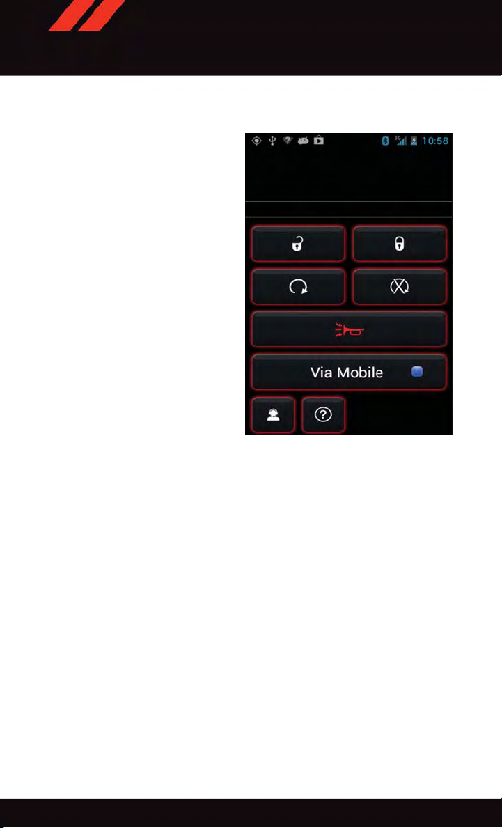
ELECTRONICS
Each time you want to use a Via Mobile app in your vehicle, the Uconnect®Access App
must be running on your smartphone and the smartphone must be paired via Bluetooth
Data Being Sent
®
.
78
Page 81

ELECTRONICS
If equipped, the Via Mobile apps can be found by selecting the “Apps” button on the
touchscreen in the lower right corner of the radio touchscreen. Via Mobile apps are listed
under the “All Apps” tab. The words “Via Mobile” will appear after the app name
indicating it is a Via Mobile app.
All Apps
1—CatagoryTabs 2—AppsButton
79
Page 82

ELECTRONICS
Via Mobile apps can also be launched through Voice Recognition by pressing the VR
button on the steering wheel and stating “launch” and then the name of the app. For
example, you can say “launch Aha Via Mobile.”
NOTE:
For detailed information on how to use Via Mobile apps visit the Mopar Owner Connect
website (moparownerconnect.com) and login using the username and password you set
up when registering for Uconnect
AmessagewillbedisplayedtoremindyouthatViaMobileappsutilizethedataplanon
your connected smartphone to provide content. Many smartphones have a limit to how
much data they can utilize before incurring additional charges. The amount of data being
used varies by smartphone device, cellular service provider and specific app. Check your
mobile phone service plan for more details.* Press “OK” to continue or the “X” to exit.
(*Additional smartphone data usage charges may apply.)
Via Mobile Apps — If Equipped
• Aha™ by HARMAN —Aha™byHARMANmakesiteasytoinstantlyaccessyour
favorite Web content on the go. Choose from over 40,000+ stations spanning internet
radio, personalized music, news, entertainment, hotels, weather, audiobooks,
Facebook
• iHeartRadio —iHeartRadioprovidesinstantaccesstomorethan1,500liveradio
stations from across the country and allows listeners to create custom music stations
inspired by their favorite artists or songs.
• Pandora® —Pandora
anywhere. Personalized stations launch instantly, with the input of a favorite artist,
track, comedian, or genre.
• Slacker Radio —Enjoymillionsofsongsandhundredsofhandcraftedstations.
NOTE:
For detailed information on how to use Via Mobile apps visit the Mopar Owner Connect
website (moparownerconnect.com) and log in using the username and password you set
up when registering for Uconnect
®
,Twitter®,andmore.
®
Access.
®
gives people the music and comedy they love anytime,
®
Access.
80
Page 83

Uconnect® 5.0
ELECTRONICS
Uconnect® 5.0
1—RadioModeButton
2—PresetButtons
3—CompassInformationButton
4—ClimateFunctionsButton
5—+MOREFunctionsButton
6—AudioButton
7—InfoButton
8—DirectTuneButton
9—AM/FM/SXMButton
10 — SEEK Up Button
11 — SEEK Down Button
12 — Uconnect
13 — Media Mode Button
®
Phone Button
Clock Setting
To sta r t the c l ock s e tti ng pr o ced u re:
1. Push the + MORE button on the faceplate. Next press the “Settings” button on the
touchscreen and then press the “Clock and Date” button on the touchscreen.
2. Press the “Set T ime” button on the touchscreen.
3. Press the “Up” or “Down” arrows to adjust the hours or minutes, then select the “AM”
or “PM” button on the touchscreen. You can also select 12hr or 24hr format by
pressing the desired button on the touchscreen.
Once the time is set press the “Done” button on the touchscreen to exit the time screen.
4.
NOTE:
In the Clock Setting Menu you can also select Display Clock. Display Clock turns the clock
display in the status bar on or off.
81
Page 84

ELECTRONICS
Equalizer, Balance And Fade
To adj u st th e A udi o s ett ing s :
1. Push the + MORE button on the faceplate, then press the “Settings” button on the
touchscreen.
2. Scroll down and press the “Audio” button on the touchscreen to open the Audio menu.
The Audio Menu shows the following options for you to customize your audio settings.
Equalizer
•Pressthe“Equalizer”buttononthetouchscreentoadjusttheBass,MidandTreble.
Use the “+” or “–” button on the touchscreen to adjust the equalizer to your desired
settings. Press the “back arrow” button on the touchscreen when done.
Balance/Fade
•Pressthe“Balance/Fade”buttononthetouchscreentoadjustthesoundfromthe
speakers. Use the “arrow” button on the touchscreen to adjust the sound level from the
front and rear or right and left side speakers. Press the Center “C” button on the
touchscreen to reset the balance and fade to the factory setting. Press the “back arrow”
button on the touchscreen when done.
Speed Adjustable
•Pressthe“SpeedAdjustedVolume”buttononthetouchscreentoselectbetweenOFF,
1, 2 or 3. This will decrease the radio volume relative to a decrease in vehicle speed.
Press the “back arrow” button on the touchscreen when done.
Loudness
•Pressthe“Loudness”buttononthetouchscreentoselecttheLoudnessfeature.When
this feature is activated it improves sound quality at lower volumes. Press the “back
arrow” button on the touchscreen when done.
Radio Operation
Seek Up /Seek Down
•PresstoseekthroughradiostationsinAM,FMorSXMbands.
•Holdeitherbuttontobypassstationswithoutstopping.
Store Radio Presets
When you are receiving a station that you wish to commit into memory , press and hold the
desired numbered button on the touchscreen for more that two seconds or until you hear
aconfirmationbeep.
The Radio stores up to 12 presets in each of the Radio modes. Four presets are visible at
the top of the radio screen. Pressing the “All” button on the touchscreen on the radio
home screen will display all of the preset stations for that mode.
82
Page 85

ELECTRONICS
SiriusXM Premier Over 160 channels
Get every channel available on your satellite radio, and enjoy all you want, all in one place.
Hear commercial-free music plus sports, news, talk and entertainment. Get all the
premium programming, including Howard Stern, every NFL game, Oprah Radio
®
MLB
and NHL®game, every NASCAR®race, Martha Stewart and more. And get 20+
extra channels, including SiriusXM Latino, offering 20 channels of commercial free
music, news, talk, comedy, sports and more dedicated to Spanish language programming.
•ToaccessSiriusXM™SatelliteRadio,pushthe“RADIO”buttononthefaceplateand
then the “SXM” button on the touchscreen.
SiriusXM services require subscriptions, sold separately after the 12-month trial included
with the new vehicle purchase. If you decide to continue your service at the end of your
trial subscription, the plan you choose will automatically renew and bill at then-current
rates until you call SiriusXM at 1-866-635-2349 for U.S. residents and 1-888-539-7474
for Canadian residents to cancel. See SiriusXM Customer Agreement for complete terms
at www.siriusxm.com for U.S. residents and www.siriusxm.ca for Canadian residents. All
fees and programming subject to change. Our satellite service is available only to those at
least 18 and older in the 48 contiguous USA and D.C. Our Sirius satellite service is also
available in PR (with coverage limitations). Our Internet radio service is available
throughout our satellite service area and in AK and HI. © 2014 Sirius XM Radio Inc.
Sirius, XM and all related marks and logos are trademarks of Sirius XM Radio Inc.
MEDIA HUB — iPod®/USB/MP3/SD Card
USB/iPod®
®
•USB/iPod
the USB port or by pushing the MEDIA button located left of the display. Once in Media
Mode, press the “source” button on the touchscreen and select “USB/iPod.”
•PushtheMEDIAbuttononthefaceplatethenpressthe“source”buttononthe
touchscreen. Select “USB/iPod” to change the mode to the USB device if the device is
connected, allowing the music from your portable device to play through the vehicle's
speakers.
Mode is entered by either inserting a USB Jump Drive or iPod®cable into
®
,every
83
Page 86

ELECTRONICS
Audio Jack (AUX)
The AUX allows a portable device, such as an MP3 player or an iPod
the radio and utilize the vehicle’s audio system, using a 3.5 mm stereo audio cable, to
amplify the source and play through the vehicle speakers.
•PushtheMEDIAbuttononthefaceplate,thenpressthe“source”buttononthe
touchscreen and select “AUX” to change the mode to auxiliary device if the audio jack
is connected, allowing the music from your portable device to play through the vehicle's
speakers.
The functions of the portable device are controlled using the device buttons, not the
buttons on the radio. The volume may be controlled using the radio or portable device.
Bluetooth®
If using a Bluetooth
vehicle's sound system.
•PushtheMEDIAbuttononthefaceplate,thenpressthe“source”buttononthe
touchscreen. Select “Bluetooth” to change the mode to Bluetooth
paired, allowing the music from your portable device to play through the vehicle's
speakers.
SD Card
SD Card Mode allows you to play music that has been saved to your SD Card through your
vehicle’s sound system.
•YoucanenterSDCardModebyeitherinsertingaSDCardintotheSDCardslotorby
pushing the “SD Card” button on the left side of the display while in media mode.
For further information refer to your Radio Supplement.
®
-equippeddevice,youmayalsobeabletostreammusictoyour
®
,tobepluggedinto
®
if the device is
84
Page 87

ELECTRONICS
Uconnect® 5.0 VOICE RECOGNITION QUICK TIPS
Introducing Uconnect®
Start using Uconnect®Voice Recognition with these helpful quick tips. It provides the key
Voice Commands and tips you need to know to control your Uconnect
Key Features:
•5”touchscreen
•Threebuttonsoneithersideofthedisplay
®
5.0 system.
Uconnect® 5.0
85
Page 88

ELECTRONICS
Get Started
1. Visit UconnectPhone.com to check mobile device and feature compatibility and to find
phone pairing instructions.
2. Reduce background noise. Wind and passenger conversations are examples of noise
that may impact recognition.
3. Speak clearly at a normal pace and volume while facing straight ahead. The micro-
phone is positioned on the rearview mirror and aimed at the driver.
4. Each time you give a Voice Command, you must first push either the VR or Phone
button, wait until after the beep, then say your Voice Command.
5. You can interrupt the help message or system prompts by pushing the VR or Phone
button and saying a Voice Command from current category .
®
All you need to control your Uconnect
steering wheel.
system with your voice are the buttons on your
Uconnect® VR/Phone Buttons
1—PushToInitiateOrToAnswerAPhoneCall,SendOrReceiveAText
2—PushToBeginRadioOrMediaFunctions
3—PushToEndCall
86
Page 89

ELECTRONICS
Basic Voice Commands
The basic Voice Commands below can be given at any point while using your Uconnect
system.
Push the VR button
• Cancel to stop a current voice session
• Help to hear a list of suggested Voice Commands
• Repeat to listen to the system prompts again
Notice the visual cues that inform you of your voice recognition system’s status. Cues
appear on the touchscreen.
.Afterthebeep,say:
®
Uconnect® 5.0 Visual Cues
87
Page 90

ELECTRONICS
Radio
Use your voice to quickly get to the AM, FM or SiriusXM™ Satellite Radio®stations you
would like to hear. (Subscription or included SiriusXM™ Satellite Radio trial required.)
Push the VR button
• Tune to ninety-five-point-five FM
• Tune to Satellite Channel Hits 1
TIP: At any time, if you are not sure of what to say or want to learn a Voice Command, push
the VR button
commands.
.Afterthebeep,say:
and say “Help.” The system will provide you with a list of
88
Uconnect® 5.0 Radio
Page 91

ELECTRONICS
Media
Uconnect®offers connections via USB, SD, Bluetooth®and auxiliary ports (If Equipped).
Voice operation is only available for connected USB and iPod
player optional and not available on all vehicles.)
Push the VR button
follow the prompts to switch your media source or choose an artist.
• Change source to Bluetooth
• Change source to iPod
• Change source to USB
• Play artist Beethoven; Play album Greatest Hits; Play song Moonlight Sonata; Play
genre Classical
TIP: Press the Browse button on the touchscreen to see all of the music on your iPod
USB device. Y our Voice Command must match exactly how the artist, album, song and
genre information is displayed.
.Afterthebeep,sayoneofthefollowingcommandsand
®
®
®
devices. (Remote CD
®
or
Uconnect® 5.0 Media
89
Page 92

ELECTRONICS
Phone
Making and answering hands-free phone calls is easy with Uconnect®.Whenthe
Phonebook button is illuminated on your touchscreen, your system is ready .
U.S. residents can visit UconnectPhone.com to check mobile device and feature compatibility and to find phone pairing instructions.
Push the Phone button
• Call John Smith
• Dial 123-456-7890 and follow the system prompts
• Redial (call previous outgoing phone number)
• Call back (call previous incoming phone number)
TIP: When providing a VoiceCommand, push the Phone button
pronounce the name exactly as it appears in your phone book. When a contact has
multiple phone numbers, you can say “Call John Smith work.”
.Afterthebeep,sayoneofthefollowingcommands…
and say “Call,” then
90
Uconnect® 5.0 Phone
Page 93

ELECTRONICS
Additional Information
©2014ChryslerGroupLLC.Allrightsreserved.Mopar,MoparOwnerConnectand
Uconnect are registered trademarks of Chrysler Group LLC. Android is a trademark of
Google Inc. SiriusXM and all related marks and logos are trademarks of SiriusXM Radio
Inc. Yelp, Yelp logo, Yelp burst and related marks are registered trademarks of Yelp.
Uconnect
•U.S.residentsvisitDriveUconnect.comorcall:1-877-855-8400
•CanadianresidentsvisitDriveUconnect.caorcall:1-800-465-2001(English)or
Mon. – Fri., 7:00 am – 12:00 am, ET
Sat., 8:00 am – 10:00 pm, ET
Sun., 9:00 am – 5:00 pm, ET
Uconnect
Security PIN ready when you call.
®
System Support:
1-800-387-9983 (French)
®
Access Services Support 1-855-792-4241. Please have your Uconnect
®
91
Page 94

ELECTRONICS
Uconnect® 8.4A
Uconnect® 8.4A — If Equipped
At A Glance
Uconnect® 8.4A
1—StatusBar
2—MenuBar
3—Uconnect
4—Uconnect
Displaying The Time
If the time is not currently displayed on the radio or player main page:
1. Press the “Controls” button on the touchscreen or the “Apps” button on the touch-
screen, then the “Settings” button on the touchscreen.
2. In the Settings list, press the “Clock” button on the touchscreen.
®
Apps Button
®
Phone Button
5—ClimateButton
6—ControlsButton
7—MediaButton
8—RadioButton
92
Page 95

ELECTRONICS
Setting The Time
Model 8.4AN synchronizes time automatically via GPS, so it should not require any time
adjustment. If you do need to set the time manually, follow the instructions below for
Model 8.4A.
1. Turn the unit on, then press the “Time Display” at the top of the screen. Press “Yes.”
NOTE:
If the time is not displayed at the top of the screen, press the “Controls” or the “Apps”
button on the touchscreen, then the “Settings” button on the touchscreen. In the Settings
screen, press the “Clock” button on the touchscreen.
2. Press “+” or “–” next to Set T ime Hours and Set Time Minutes to adjust the time.
3. If these features are not available, uncheck the Sync with GPS box.
4. Press “X” to save your settings and exit out of the Clock Setting screen.
Audio Settings
To adj u st th e A udi o s ett ing s :
1. Press the “Media” or “Radio” button on the touchscreen.
2. Press the “Audio” button on the touchscreen to activate the Audio settings screen to
adjust Balance/Fade, Equalizer and Speed Adjusted Volume.
3. You can return to the Radio screen by pressing the “X” located at the top right.
Balance/Fade
To adj u st th e B ala nce / Fad e s ett ing s :
1. Press the “Media” or “Radio” button on the touchscreen.
2. Press the “Audio” button on the touchscreen to activate the Audio settings screen to
adjust Balance/Fade, Equalizer and Speed Adjusted Volume.
3. Press the “Balance/Fade” button on the touchscreen to Balance audio between the
front speakers or fade the audio between the rear and front speakers.
4. Pressing the “Front,” “Rear,” “Left” or “Right” button on the touchscreens or press
and drag the Speaker Icon to adjust the Balance/Fade.
Equalizer
To adj u st th e e qua liz e r set t ing s:
1. Press the “Media” or “Radio” button on the touchscreen.
2. Press the “Audio” button on the touchscreen to activate the Audio settings screen to
adjust Balance/Fade, Equalizer and Speed Adjusted Volume.
93
Page 96

ELECTRONICS
3. Press the “Equalizer” button on the touchscreen to activate the Equalizer screen.
4. Press the “+” or “–” button on the touchscreens, or by pressing and dragging over the
“level bar” for each of the equalizer bands. The level value, which spans between plus
or minus 9, is displayed at the bottom of each of the Bands.
Speed Adjusted Volume
To adj u st th e s pee d a dju ste d v olu m e set tin g s:
1. Press the “Media” or “Radio” button on the touchscreen.
2. Press the “Audio” button on the touchscreen to activate the Audio settings screen to
adjust Balance/Fade, Equalizer and Speed Adjusted Volume.
3. Press the “Speed Adjusted Volume” button on the touchscreen to activate the Speed
Adjusted Volume screen. The Speed Adjusted Volume is adjusted by pressing the
“volume level” indicator. This alters the automatic adjustment of the audio volume
with variation to vehicle speed.
Surround Sound
To tur n s urr ound s oun d O n/O f f:
1. Press the “Media” or “Radio” button on the touchscreen.
2. Press the “Audio” button on the touchscreen to activate the Audio settings screen to
adjust Balance/Fade, Equalizer and Speed Adjusted Volume.
3. Press the “Surround Sound” button on the touchscreen, select On or Off followed by
pressing the “back arrow” button on the touchscreen. When this feature is activated,
it provides simulated surround sound mode.
94
Page 97

RADIO
1—RadioStationPresets
2—ToggleBetweenPresets
3—AudioSetting
4—SeekUp
ELECTRONICS
Uconnect® 8.4A Radio
5—DirectTuneToARadioStation
6—SeekDown
7—BrowseAndManagePresets
8—ChooseRadioBand
To acc e ss th e R adi o m ode :
•Pressthe“Radio”buttonatthelowerleftofthetouchscreen.
Selecting Radio Stations
•Pressthedesiredradioband(AM,FMorSXM)buttononthetouchscreen.
Seek Up
•Pressthe“Seekarrow”buttononthetouchscreenforlessthantwosecondstoseek
through radio stations.
•Pressandholdeither“Seekarrow”buttononthetouchscreenformorethantwo
seconds to bypass stations without stopping. The radio will stop at the next listenable
station once the “arrow” button on the touchscreen is released.
/Seek Down
95
Page 98

ELECTRONICS
Direct Tune
•Tunedirectlytoaradiostationbypressingthe“Tune”buttononthescreen,and
entering the desired station number.
Store Radio Presets
Your radio c an stor e 36 total preset st ations, 1 2 presets per band ( AM, FM an d SXM). T hey
are shown at the top of your radio screen.
•Toseethe12presetstationsperband,pressthe“arrow”buttononthetouchscreenat
the top right of the screen to toggle between the two sets of six presets.
•Tosetastationintomemorypressandholdthedesirednumberedbuttononthe
touchscreen for more than two seconds or until you hear a confirmation beep.
SiriusXM Premier Over 160 Channels
Get every channel available on your satellite radio, and enjoy all you want, all in one place.
Hear commercial-free music plus sports, news, talk and entertainment. Get all the premium
programming, including Howard Stern, every NFL game, Oprah Radio
®
NHL
game, every NASCAR®race and more. And get 20+ Xtra channels, including SiriusXM
Latino, a selection of channels dedicated to Spanish language programming.
•ToaccessSiriusXMSatelliteRadio,pressthe“SXM”buttononthetouchscreenonthe
main Radio screen.
The following describes features that are available when in SiriusXM Satellite Radio mode.
Seek Up /Seek Down
•Pressthe“Seekarrow”buttononthetouchscreenforlessthantwosecondstoseek
through channels in SXM mode.
•Pressandholdeither“Seekarrow”buttononthetouchscreenformorethantwo
seconds to bypass channels without stopping. The radio will stop at the next listenable
channel once the arrow button on the touchscreen is released.
Direct Tune
•TunedirectlytoaSXMchannelbypressingthe“Tune”buttononthetouchscreen,and
entering the desired station number.
Jump
Jump automatically tells you when Traffic & Weather for a favorite city is available, and
gives you the option to switch to that channel.
•Press“Jump”toactivatethefeature.AfterlisteningtoTrafficandWeather,press
“Jump” again to return to the previous channel.
®
,everyMLB®and
96
Page 99
ELECTRONICS
Fav
Activates the favorites menu. You can add up to 50 favorite artists or songs.
•JustpressAddFavArtistorAddFavSongwhilethesongisplaying.Youwillthenbe
alerted any time one of these songs, or works by these artists, is playing on other
SiriusXM channels.
SiriusXM Parental Controls
You can skip or hi de ce rt ain channels from view if you do not want access to th em.
•Pressthe“Apps”buttononthetouchscreen,thenthe“Settings”buttononthe
touchscreen. Next press the “Sirius Setup” button on the touchscreen, and select
“Channel Skip”. Press the box next to the channel you want skipped. They will not show
up in normal usage.
SiriusXM also offers the option to permanently block selected channels. Call
(1-888-601-6297 for U.S. customers, 1-877-438-9677 for Canadian customers) and
request the Family-Friendly Package.
Browse
Lets you browse the SiriusXM channel listing or Genre listing. Favorites, Game Zone,
Weather and Jump settings also provide a way to browse the SiriusXM channel list.
Browse
Sub-Menu
All Shows the channel listing.
Genre Provides a list of all genres, and lets you jump to a channel within the selected
Presets Lets you scroll the list of Preset satellite channels. Press the channel, or press
Favorites Lets you manage artists and songs in the Favorites list and configure Alert
Game Zone Provides alerts when your favorite sports teams are starting a game which is
Jump Lets you select your favorite cities for Traffic & Weather information, which is
Sub-Menu Description
genre.
Enter on the Tune knob, to go to that channel. Press the trash can icon to
delete a preset. Your presets are also shown at the top of the main Satellite
Radio screen.
Settings to let you know when favorite songs or artists are playing on other
channels. Also, view a list of channels airing any of your Favorites.
being aired on other SiriusXM channels, or when their game score is announced. You can select and manage your T eams list here, and configure
alerts.
used by the Jump feature on the main satellite radio screen.
97
Page 100

ELECTRONICS
Replay
Lets you replay up to 44 minutes of the content of the current SiriusXM channel.
Replay Option
Play/Pause Press to Pause content playback. Press Pause/Play again to resume playback.
Rewind/RW Rewinds the channel content in steps of five seconds. Press and hold to
Fast
Forward/FW
Replay Time Displays the amount of time in the upper center of the screen by which your
Live Resumes playback of Live content at any time while replaying rewound
SiriusXM services require subscriptions, sold separately after the 12-month trial included
with the new vehicle purchase. If you decide to continue your service at the end of your
trial subscription, the plan you choose will automatically renew and bill at then-current
rates until you call SiriusXM at 1-866-635-2349 for U.S. residents and 1-888-539-7474
for Canadian residents to cancel. See SiriusXM Customer Agreement for complete terms
at www.siriusxm.com for U.S. residents and www.siriusxm.ca for Canadian residents. All
fees and programming subject to change. Our satellite service is available only to those at
least 18 and older in the 48 contiguous USA and D.C. Our Sirius satellite service is also
available in PR (with coverage limitations). Our Internet radio service is available
throughout our satellite service area and in AK and HI. © 2014 Sirius XM Radio Inc.
Sirius, XM and all related marks and logos are trademarks of Sirius XM Radio Inc.
Option Description
rewind continuously, then release to begin playing content at that point.
Forwards the content, and works similarly to Rewind/RW. However, Fast
Forward/FW can only be used when content has been previously rewound.
content lags the Live channel.
content.
MEDIA HUB — iPod®/USB/MP3/SD Card
There are many ways to play music from iPod®/MP3 players or USB devices through your
vehicle's sound system.
•Pressyour“Media”buttononthetouchscreen to begin.
USB Port
®
Connect your iPod
using a USB cable into the USB Port. USB
Memory sticks with audio files can also be
used. Audio from the device can be played
on the vehicle's sound system while providing metadata (artist, track title, album, etc.)
information on the radio display.
When connected, the iPod
USB device can be controlled using the
radio or Steering Wheel Audio Controls to play, skip to the next or previous track, browse,
and list the contents.
or compatible device
®
/compatible
Uconnect® Media Hub
1—AUXPort
2—USBPort
3—SDCardSlot
98
 Loading...