

Page 1
CHALLENGER
USER GUIDE
2013
Includes SRT8
Page 2
If you are the first registered retail owner of your vehicle, you
may obtain a complimentary printed copy of the Owner’s
Manual, Navigation/Uconnect® Manuals or Warranty Booklet
by calling 1-800-423-6343 (U.S.) or 1-800-387-1143 (Canada)
or by contacting your dealer.
IMPORTANT
This User Guide is intended to familiarize you with the important features of your vehicle.
The DVD enclosed contains your Owner’s Manual, Navigation/Uconnect
Booklets, Tire Warranty and Roadside Assistance (new vehicles purchased in the U.S.) or
Roadside Assistance (new vehicles purchased in Canada) in electronic format. We hope you
find it useful. Replacement DVD kits may be purchased by visiting www.techauthority.com.
Copyright 2013 Chrysler Group LLC.
The driver ’s primary responsibility is the safe operation of the vehicle. Driving while distracted
can result in loss of vehicle control, resulting in a collision and personal injury. Chrysler Group
LLC strongly recommends that the driver use extreme caution when using any device or feature
that may take their attention off the road. Use of any electrical devices such as cell phones,
computers, portable radios, vehicle navigation or other devices by the driver while the vehicle
is moving is dangerous and could lead to a serious collision. Texting while driving is also
dangerous and should never be done while the vehicle is moving. If you find yourself unable
to devote your full attention to vehicle operation, pull off the road to a safe location and stop
your vehicle. Some States or Provinces prohibit the use of cellular telephones or texting while
driving. It is always the driver ’s responsibility to comply with all local laws.
®
Manuals, Warranty
Page 3

TABLE OF CONTENTS
INTRODUCTION/WELCOME
WELCOME FROM CHRYSLER GROUP LLC . . . 2
CONTROLS AT A GLANCE
DRIVER COCKPIT ................4
INSTRUMENT CLUSTER .............6
GETTING STARTED
KEY FOB . . . . . . . . . . . . . . . . . . . . . 8
REMOTE START .................9
KEYLESS ENTER-N-GO™ ...........10
THEFT ALARM .................14
SEAT BELT . . . . . . . . . . . . . . . . . . . 15
SUPPLEMENTAL RESTRAINT SYSTEM (SRS) —
AIR BAGS . . . . . . . . . . . . . . . . . . . . 16
CHILD RESTRAINTS ..............17
FRONT SEATS .................19
REAR SEAT . . . . . . . . . . . . . . . . . . . 21
HEATED SEATS . . . . . . . . . . . . . . . . 22
TILT/TELESCOPING STEERING COLUMN . . . 23
OPERATING YOUR VEHICLE
ENGINE BREAK-IN RECOMMENDATIONS . . . 24
TURN SIGNAL/WIPER/WASHER/HIGH BEAM
LEVER ......................25
HEADLIGHT SWITCH ..............26
SPEED CONTROL ................27
AUTOSTICK® ..................28
SPORT MODE – IF EQUIPPED .........29
MANUAL TRANSMISSION 1 TO 4 SKIP SHIFT . . . 29
MANUAL CLIMATE CONTROLS ........30
AUTOMATIC TEMPERATURE
CONTROLS (ATC) ................31
POWER SUNROOF ...............32
WIND BUFFETING ...............33
ELECTRONICS
YOUR VEHICLE'S SOUND SYSTEM ......34
Uconnect® 130 .................36
Uconnect® 130 WITH SiriusXM SATELLITE
RADIO . . . . . . . . . . . . . . . . . . . . . . 38
Uconnect® 430/430N .............40
Uconnect® 730N ................50
SiriusXM SATELLITE RADIO/TRAVEL LINK . . 61
STEERING WHEEL AUDIO CONTROLS ....64
Uconnect® Phone ...............64
Uconnect® VOICE COMMAND .........67
Bluetooth® STREAMING AUDIO ........69
iPod®/USB/MP3 CONTROL ..........70
ELECTRONIC VEHICLE INFORMATION CENTER
(EVIC) . . . . . . . . . . . . . . . . . . . . . . 71
PROGRAMMABLE FEATURES .........72
UNIVERSAL GARAGE DOOR OPENER
(HomeLink®) ..................73
POWER OUTLETS ...............76
UTILITY
TRAILER TOWING WEIGHTS (MAXIMUM
TRAILER WEIGHT RATINGS) . . . . . . . . . . 7 7
RECREATIONAL TOWING (BEHIND
MOTORHOME, ETC.) ..............77
SRT8
AUTOSTICK® ..................79
ELECTRONIC CONTROL DAMPING
SYSTEM .....................80
PERFORMANCE FEATURES ..........81
SUMMER/THREE-SEASON TIRES .......82
WHAT TO DO IN EMERGENCIES
ROADSIDE ASSISTANCE ............83
INSTRUMENT CLUSTER WARNING LIGHTS . . 83
IF YOUR ENGINE OVERHEATS .........88
JACKING AND TIRE CHANGING ........89
BATTERY LOCATION ..............95
TIREFIT KIT ..................95
JUMP-STARTING ...............101
SHIFT LEVER OVERRIDE ...........103
TOWING A DISABLED VEHICLE .......103
FREEING A STUCK VEHICLE .........105
EVENT DATA RECORDER (EDR) ........106
MAINTAINING YOUR VEHICLE
OPENING THE HOOD .............107
ENGINE COMPARTMENT ...........108
FLUIDS AND CAPACITIES - NON SRT8 ....111
MAINTENANCE SCHEDULE ..........114
FUSES .....................122
TIRE PRESSURES ...............125
WHEEL AND WHEEL TRIM CARE ......125
EXTERIOR BULBS ..............126
CONSUMER ASSISTANCE
CHRYSLER GROUP LLC CUSTOMER
CENTER ....................127
CHRYSLER CANADA INC. CUSTOMER
CENTER ....................127
ASSISTANCE FOR THE HEARING
IMPAIRED . . . . . . . . . . . . . . . . . . . 127
PUBLICATIONS ORDERING ..........127
REPORTING SAFETY DEFECTS IN THE UNITED
STATES . . . . . . . . . . . . . . . . . . . . 128
MOPAR ACCESSORIES
AUTHENTIC ACCESSORIES BY MOPAR® . . 129
FAQ (How To?)
FREQUENTLY ASKED QUESTIONS ......130
INDEX
....................132
Page 4

INTRODUCTION/WELCOME
WELCOME FROM CHRYSLER GROUP LLC
Congratulations on selecting your new Chrysler Group LLC vehicle. Be assured that it
represents precision workmanship, distinctive styling, and high quality - all essentials that
are traditional to our vehicles.
Your n e w Chr y s l e r Group LLC vehicle h as characteristics to e n h a n c e the driver's c o n t r o l
under some driving conditions. These are to assist the driver and are never a substitute for
attentive driving. They can never take the driver's place. Always drive carefully.
Your new vehicle ha s m a n y f e a t u r e s f o r t h e c o m f o r t a n d c o n v e n i e n c e of y o u a n d yo u r
passengers. Some of these should not be used when driving because they take your eyes
from the road or yourattention from driving. Never text while driving or take your eyes more
than momentarily off the road.
This guide illustrates and describes the operation of featuresand equipmentthat areeither
standard or optional on this vehicle. This guide may also include a description of features
and equipment that are no longer available or were not ordered on this vehicle. Please
disregard any features and equipment described in this guide that are not available on this
vehicle. Chrysler Group LLC reserves the right to make changes in design and specifications and/or make additions to or improvements to its products without imposing any
obligation upon itself to install them on products previously manufactured.
This User Guide has been prepared to help you quickly become acquainted with the
important features of your vehicle. It contains most things you will need to operate and
maintain the vehicle, including emergency information.
The DVD includes a computer application containing detailed owner's information which
can be viewed on a personalcomputer orMAC computer.The multimediaDVD alsoincludes
videos which can be played on any standard DVD player (including the Uconnect® TouchScreen Radios). Additional DVD operational information is located on the back of the DVD
sleeve.
For complete owner information, referto your Owner's Manual on the DVDin the owner’s
kit provided at the time of new vehicle purchase. For your convenience, the information
contained on the DVD may also be printed and saved for future reference.
Chrysler Group LLC is committed to protecting our environment and natural resources. By
converting frompaper toelectronic delivery for the majority ofthe user information foryour
vehicle, together we greatly reduce the demand for tree-based products and lessen the
stress on our environment.
2
Page 5
INTRODUCTION/WELCOME
VEHICLES SOLD IN CANADA
With respect to any vehicles sold in Canada, the name Chrysler Group LLC shall be deemed
to be deleted and the name Chrysler Canada Inc. used in substitution.
WARNING!
• Pedals that cannot move freely can cause loss of vehicle control and increase the
risk of serious personal injury.
•Alwaysmakesurethatobjectscannotfallintothedriverfootwellwhilethevehicleis
moving. Objects can become trapped under the brake pedal and accelerator pedal
causing a loss of vehicle control.
• Failure to properly follow floor mat installation or mounting can cause interference
with the brake pedal and accelerator pedal operation causing loss of control of the
vehicle.
• Never use the ‘PARK’ position as a substitute for the parking brake. Always apply the
parking brake fully when parked to guard against vehicle movement and possible
injury or damage.
•RefertoyourOwner'sManualontheDVDforfurtherdetails.
USE OF AFTERMARKET PRODUCTS (ELECTRONICS)
The use of aftermarket devices including cell phones, MP3 players, GPS systems, or
chargers may affect the performance of on-board wireless features including Keyless
Enter-N-Go™ and Remote Start range. If you are experiencing difficulties with any of your
wireless features, try disconnecting your aftermarket devices to see if the situation improves. If your symptoms persist, please see an authorized dealer.
CHRYSLER, DODGE, JEEP, RAM TRUCK, SRT, ATF+4, MOPAR and Uconnect are registered
trademarks of Chrysler Group LLC.
COPYRIGHT ©2013 CHRYSLER GROUP LLC
3
Page 6
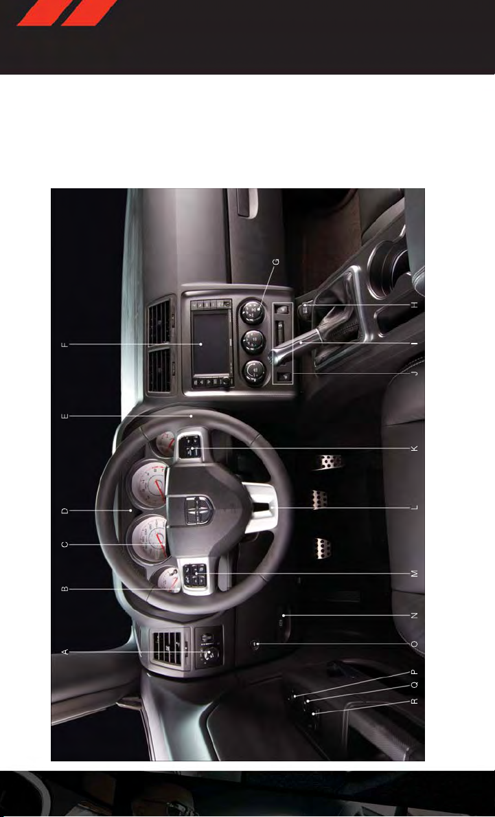
CONTROLS AT A GL ANCE
DRIVER COCKPIT
4
Page 7

CONTROLS AT A GL ANCE
M. EVIC Controls pg. 7 1
N. Parking Brake Pedal
O. Trunk Release Button
P. Po we r M i r r o r s
Q. Power Door Locks
R. Power Windows
F. Au di o S y st e m (t o uc h- s c re e n ra d io
A. Headlight Switch pg. 26
shown) pg. 34
B. Turn Signal/Wiper/Washer/High Beams
G. Climate Controls pg. 30
Lever (behind steering wheel) pg. 25
H. Power Outlet pg. 76
(EVIC) Display (behind steering wheel)
C. Electronic Vehicle Information Center
• Heated Seat Switches pg. 22
• Hazard Switch
• Electronic Stability Control pg. 83
I. Transmission Shift Lever
J. SWITCH PANEL
Transmission pg. 12
pg. 71
D. Instrument Cluster pg. 6
•Engine Starting/Stopping - Automatic
Button (behind steering wheel)
E. Ignition Switch/Keyless Enter-N-Go™
base of instrument panel) pg. 107
K. Speed Control pg. 27
L. Hood Release (below steering wheel at
Transmission pg. 12
•Engine Starting/Stopping - Manual
5
Page 8
CONTROLS AT A GL ANCE
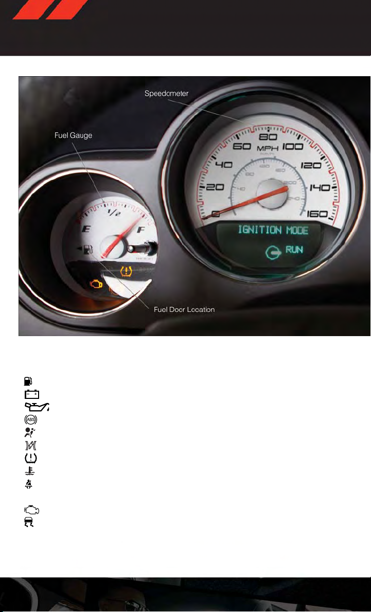
INSTRUMENT CLUSTER
Warning Lights
- Low Fuel Warning Light
- Charging System Light**
- Oil Pressure Warning Light**
-Anti-LockBrake(ABS)Light**
- Air Bag Warning Light**
- Electronic Throttle Control (ETC) Light
-TirePressureMonitoringSystem(TPMS)Light
- Engine Temperature Warning Light
- Seat Belt Reminder Light
BRAKE
(See page 83 for more information.)
6
- Brake Warning Light**
-MalfunctionIndicatorLight(MIL)**
-ElectronicStabilityControl(ESC)Activation/MalfunctionIndicatorLight*
Page 9
CONTROLS AT A GL ANCE
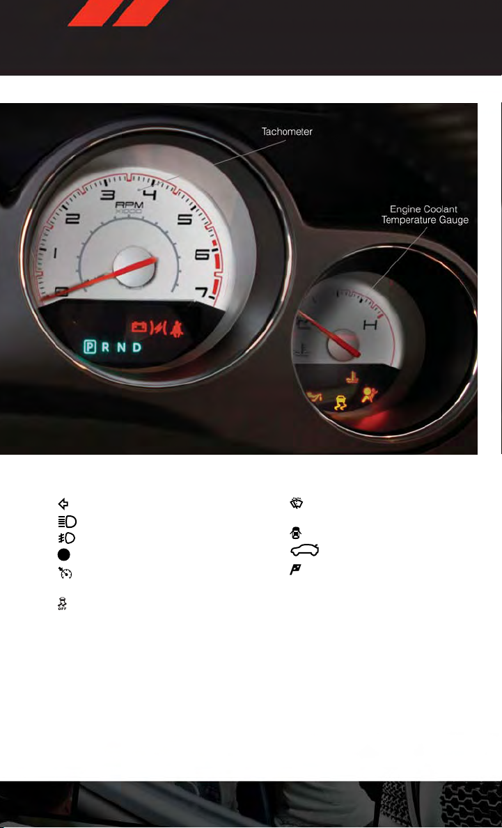
Indicators
-TurnSignalIndicators
-HighBeamIndicator
-FrontFogLightIndicator
-VehicleSecurityIndicator*
- Electronic Speed Control
Set
- Electronic Stability Control
(ESC) Off Indicator*
* If equipped
** Bulb Check with Key On
***On vehicles equipped with a Premium Instrument Cluster, this display shows the Electronic Vehicle Information Center (EVIC) messages when the appropriate conditions exist.
- Windshield Washer Fluid
Low Indicator***
-DoorAjarIndicator***
-DecklidAjarIndicator***
-SportModeIndicator
7
Page 10
GETTING STARTED
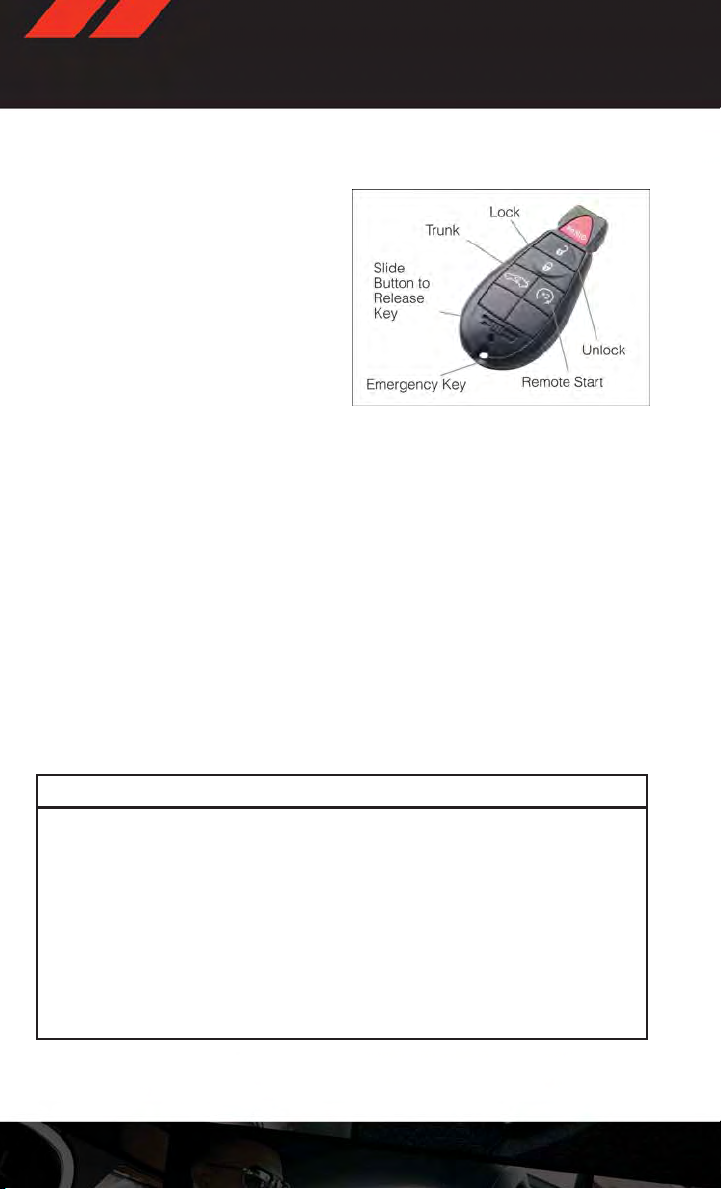
KEY FOB
Locking And Unlocking The Doors
•PressandreleasetheUNLOCKbuttonon
the RKE transmitter once to unlock the
driver’s door (EVIC can be setup for driver
door first, otherwise this will unlock all
doors), or press the unlock button twice
within five seconds to unlock all doors.
The turn signal lights will flash to acknowledge the unlock signal. The illuminated entry system will also turn on.
•Alldoorscanbeprogrammedtounlock
on the first press of the UNLOCK button. Refer to Programmable Features in this guide.
Opening The Trunk
•PresstheTRUNKbuttontwotimeswithinfivesecondstoopenthetrunk.
Panic Alarm
•PressthePANICbuttononcetoturnthepanicalarmon.
•Waitapproximatelythreesecondsandpressthebuttonasecondtimetoturnthepanic
alarm off.
Emergency Key
• Should the battery in the vehicle or the Key Fob transmitter go dead, there is an
emergency key located in the Key Fob that can be used for locking and unlocking the
doors. To remove the emergency key, slide the button at the top of the Key Fob sideways
with your thumb and then pull the key out with your other hand.
CAUTION!
• If your vehicle battery becomes low or dead, your Key Fob will become locked in the
ignition.
•DonotattempttoremovetheKeyFobwhileinthiscondition,damagecouldoccurto
the Key Fob or ignition module. Only remove the emergency key for locking and
unlocking the doors.
•LeavetheKeyFobintheignitionandeither:
• Jump Start the vehicle.
• Charge the battery.
•ContactyourauthorizeddealerforassistanceonhowtoremovetheKeyFob
using the manual override method.
8
Page 11
GETTING STARTED
WARNING!
•Neverleavechildrenaloneinavehicle,orwithaccesstoanunlockedvehicle.
Allowing children to be in avehicle unattendedis dangerousfor anumber ofreasons.
Achildorotherscouldbeseverelyinjuredorkilled.Childrenshouldbewarnednotto
touch the parking brake, brake pedal, or the shift lever.Do notleave theKey Fob inside
the vehicle, or in a location accessible to children. A child could start the vehicle,
operate power windows, other controls, or move the vehicle.
•Donotleavechildrenoranimalsinsideparkedvehiclesinhotweather.Interiorheat
build-up may cause them to be severely injured or killed.
•KeepKeyFobtransmittersawayfromchildren.OperationoftheRemoteStart
System, windows, door locks or other controls could cause serious injury or death.
REMOTE START
x
•PresstheREMOTESTARTbutton
the REMOTE START button a third time shuts the engine off.
•Todrivethevehicle,presstheUNLOCKbutton,inserttheKeyFobintheignitionandturn
to the ON/RUN position.
• With remote start, the engine will onlyrun for15 minutes(timeout) unlessthe ignitionKey
Fob is placed in the ON/RUN position.
• The vehicle must be started with the Key Fob after two consecutive timeouts.
2
on the Key Fob twice within five seconds. Pressing
WARNING!
• Do not start or run an engine in a closed garage or confined area. Exhaust gas
contains Carbon Monoxide (CO) which is odorless and colorless. Carbon Monoxide is
poisonous and can cause you or others to be severelyinjured or killed when inhaled.
•KeepKeyFobtransmittersawayfromchildren.OperationoftheRemoteStart
System, windows, door locks or other controls could cause you and others to be
severely injured or killed.
9
Page 12
GETTING STARTED
KEYLESS ENTER-N-GO™
•TheKeylessEnter-N-Go™systemisanenhancementtothevehicle'sKeyFob.This
feature allows you to lock and unlock the vehicle's door(s) and trunk without having to
press the Key Fob lockor unlock buttons, as well as starting and stopping thevehicle with
the press of a button.
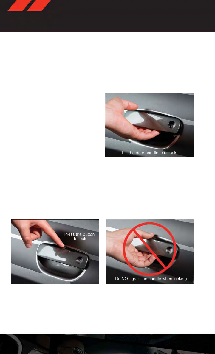
To Unlock From The Driver or Passenger Side:
•WithavalidKeylessEnter-N-Go™KeyFob
located outside the vehicle and within 5 ft
(1.5 m) of the driveror passengerside door
handle, grab either front door handle to
unlock the door automatically.
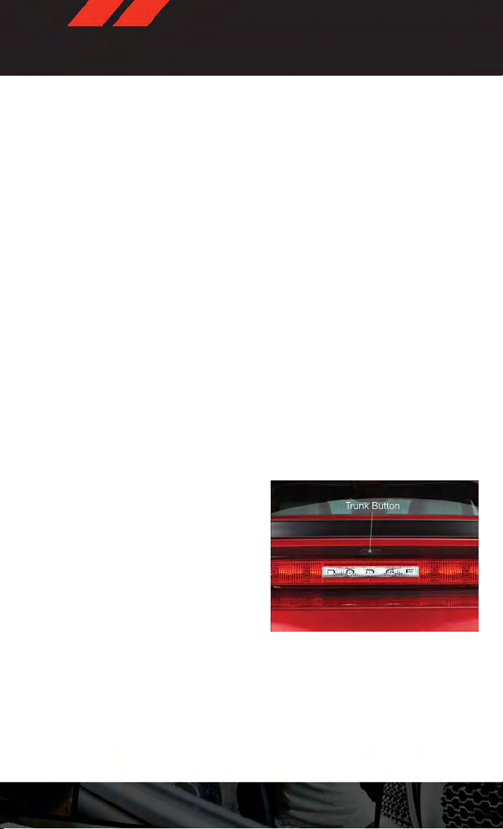
To Lock the Vehicle:
Both front door handles have LOCK buttons located on the outside of the handle. With one of
•
the vehicle's Keyless Enter-N-Go™ Key Fobs located outside the vehicle and within 5 ft (1.5 m)
of the driver's or passenger front door handle, press the door handle LOCK button to lock all
four doors and trunk.
•DONOTgrabthedoorhandle,whenpressingthedoorhandlelockbutton.Thiscould
unlock the door(s).
10
Page 13
GETTING STARTED
NOTE:
•If“UnlockAllDoors1stPress”isprogrammedalldoorswillunlockwhenyougrabholdof
the front driver's door handle. To select between “Unlock Driver Door 1st Press” and
“Unlock All Doors 1st Press”, refer to the Electronic Vehicle Information Center (EVIC) in
your vehicle's Owner's Manual on the DVD or Programmable Features in this guide for
further information.
•If“UnlockAllDoors1stPress”isprogrammedalldoorsandtrunkwillunlockwhenyou
press the trunk button. If “Unlock Driver Door 1st Press”is programmed only the trunk will
unlock whenyou press the trunk button.Toselect between“Unlock Driver Door 1st Press”
and “Unlock All Doors 1st Press”, refer to the Electronic VehicleInformation Center (EVIC)
in your vehicle's Owner's Manual on the DVD or Programmable Features in this guide for
further information.
• If a Key Fob is detected in the vehicle when locking the vehicle using the power door lock
switch, the doors and trunk will unlock and the horn will chirp three times. On the third
attempt, your Key Fob can be locked inside the vehicle.
•AfterpressingtheKeylessEnter-N-Go™LOCKbutton,youmustwait2secondsbefore
you can lock or unlock the vehicle using the door handle. This is done to allow you to
check if the vehicle is lockedby pulling the door handle, without the vehicle reacting and
unlocking.
•IfaKeylessEnter-N-Go™doorhandlehasnotbeenusedfor72hours,theKeyless
Enter-N-Go™ feature for that handle may time out. Pulling the deactivated front door
handle will reactivate the door handle's Keyless Enter-N-Go™ feature.
To En t e r t h e Trun k
•WithavalidKeylessEnter-N-Go™KeyFob
located outside the vehicle and within 3 ft
(1.0 m) of the deck lid, press the button
located on the center of the light bar
which is located on the deck lid above the
license plate.
NOTE:
Refer to your Owner's Manual on the DVD for
further information.
11
Page 14
GETTING STARTED
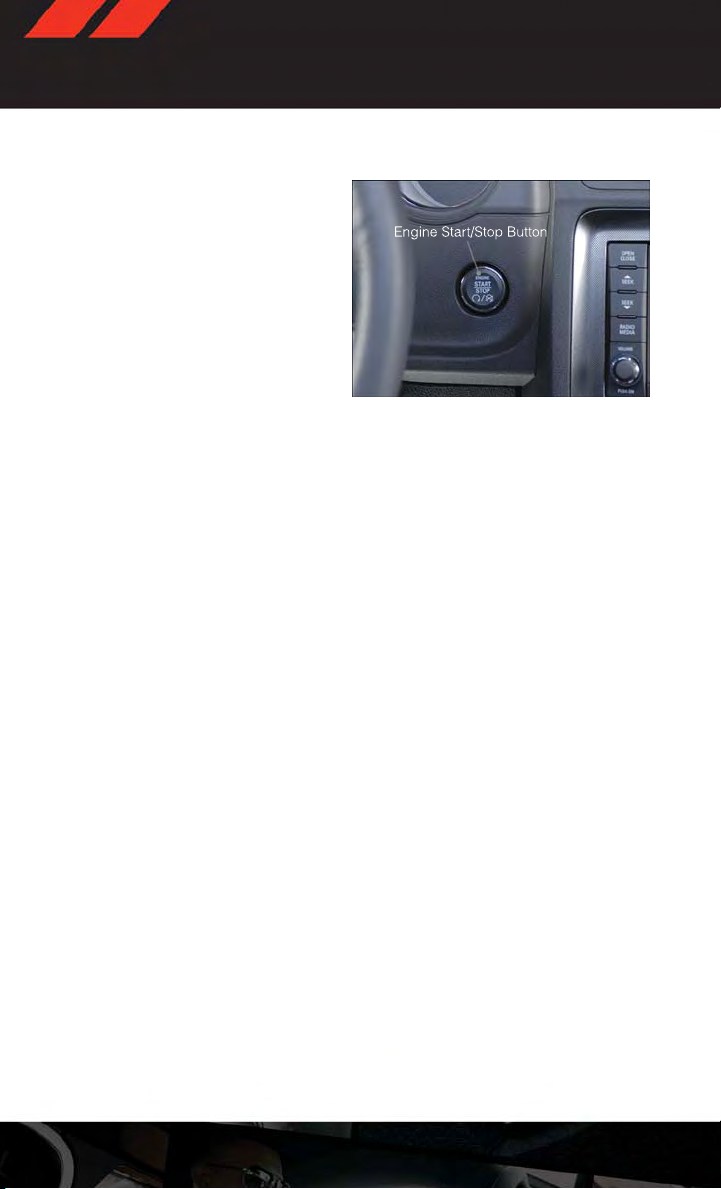
Engine Starting/Stopping - Automatic Transmission
Starting
• Place the shift lever in PARKor NEUTRAL.
• While pressing the brake pedal, press the
ENGINE START/STOP button once. If the
engine failsto start, the starter will disengage automatically after 10 seconds.
•Tostopthecrankingoftheenginepriorto
the engine starting, press the button
again.
Stopping
• Place the shift lever in PARK.
•PresstheENGINESTART/STOPbuttononce.TheignitionswitchwillreturntotheOFF
position.
• If the shift lever is not in PARK, the ENGINE START/STOP button must be held for two
seconds and vehicle speed must be above 5 mph (8 km/h) before the engine will shut
off.
NOTE:
If the ignition switch is left in the ACC or RUN (engine not running) position and the
transmission is in PARK, the system will automatically time out after 30 minutes of
inactivity and the ignition will switch to the OFF position.
Engine Starting/Stopping - Manual Transmission
Starting
• Press and hold the clutch pedal while pressing and holding the ENGINE START/STOP
button. Release the button when the engine starts. If the engine fails to start within 15
seconds, release the button, wait 10 to 15 seconds, then repeat.
•Tostopthecrankingoftheenginepriortotheenginestarting,releasethebutton.
12
Page 15
GETTING STARTED
Stopping
•Withthevehiclestopped,placetheshiftleverinNEUTRAL.
•PresstheENGINESTART/STOPbuttononce.TheignitionswitchwillreturntotheOFF
position.
• If the vehiclespeed is above 5 mph (8 km/h), the ENGINE START/STOP button must be
held for two seconds before the engine will shut off. The ignition switch position will
remain in the ACC position until the vehicle is stopped and the button is pressed twice
to the OFF position.
NOTE:
If the ignition switch is left in the ACC position, the system will automatically time out after
60 minutes of inactivity and the ignition will switch to the OFF position.
Additional Functions
NOTE:
The following functions are with the driver’s foot OFF the Brake Pedal/Clutch Pedal (Transmission in PARK or NEUTRAL Position).
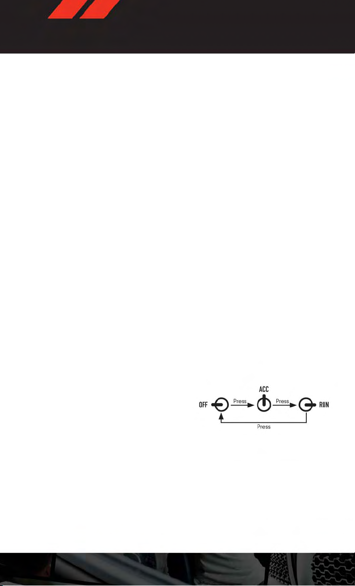
Starting With The Ignition Switch In The OFF Position:
•PresstheENGINESTART/STOPbuttononcetochangetheignitionswitchtotheACC
position.
•PresstheENGINESTART/STOPbuttonasecondtimetochangetheignitionswitchtothe
RUN position.
•PresstheENGINESTART/STOPbuttonathirdtimetoreturntheignitionswitchtotheOFF
position.
13
Page 16

GETTING STARTED
THEFT ALARM
To Arm
• Keyless Enter-N-Go™ button installed: Press the Keyless Enter-N-Go™ Start/Stop button until the Electronic Vehicle Information Center (EVIC) indicates that the vehicle
ignition is “OFF”. Press the power door lock switch while the door is open, press the Key
Fob LOCK button, or with one of the Key Fobs located outside the vehicle and within 5 ft
(1.5 m) of the driver's and passenger front door handles, press the Keyless Enter-N-Go™
LOCK button located on the door handle.
• Keyless Enter-N-Go™ button not installed: Tu rn the i g ni t io n sw i t ch t o the “ O FF ” posi tion. Press the power door lock switch while the door is open, press the Key Fob LOCK
button, or with one of the Key Fobs located outside the vehicle and within 5 ft (1.5 m) of
the driver's and passenger front door handles, press the Keyless Enter-N-Go™ LOCK
button located on the door handle.
NOTE:
After pressing the Keyless Enter-N-Go™ LOCK button, you must wait two seconds before
you can lock or unlock the vehicle via the door handle.
To Disarm
• Keyless Enter-N-Go™ button installed: Press the Key Fob UNLOCK button or with one of
the Key Fobs located outside the vehicle and within 5 ft (1.5 m) of the driver's and
passenger front door handles, grab the Keyless Enter-N-Go™ door handle and enter the
vehicle, then press the Keyless Enter-N-Go™ Start/Stop button (requires at least one
valid Key Fob in the vehicle).
• Keyless Enter-N-Go™ button not installed: Press the Key Fob UNLOCK button or with
one of the Key Fobs located outside the vehicle and within 5 ft (1.5 m) of the driver's and
passenger front door handles, grab the Keyless Enter-N-Go™ door handle and enter the
vehicle, then turn the ignition to the ON/RUN position.
14
Page 17
GETTING STARTED
SEAT BELT
• Be sure everyone in your vehicle is in a seat and using a seat belt properly.
• Position the lap belt across your thighs, below your abdomen. Toremove slack in the lap
portion, pull up a bit on the shoulder belt. To loosen the lap belt if it is too tight, tilt the
latch plate and pull on the lap belt. A snug belt reduces the risk of sliding under the belt
in a collision.
• Position the shoulder belt on your chest so that it is comfortable and not resting on your
neck. The retractor will withdraw any slack in the belt.
• A shoulder belt placed behind you will not protect you from injury during a collision. You
are more likely to hit your head in a collisionif you do not wear your shoulder belt.The lap
and shoulder belt are meant to be used together.
•Abeltthatistooloosewillnotprotectyouproperly.Inasuddenstopyoucouldmovetoo
far forward, increasing the possibility of injury. Wear your seat belt snugly.
•Afrayedortornbeltcouldripapartinacollisionandleaveyouwithnoprotection.Inspect
the belt system periodically, checking for cuts, frays,or looseparts. Damaged parts must
be replaced immediately. Do not disassemble or modify the system. Seat belt assemblies must be replaced after a collision if they have been damaged (bent retractor, torn
webbing, etc.).
• The seat belts for both front seating positions are equipped with pretensioning devices
that are designed to remove slack from the seat belt in the event of a collision.
• A deployed pretensioner or a deployed air bag must be replaced immediately.
WARNING!
In a collision, you and your passengers can suffer much greater injuries if you are not
buckled up properly. You can strike the interior of your vehicle or other passengers, or you
can be thrown out of the vehicle. Always be sure you and others in your vehicle are
buckled up properly.
15
Page 18
GETTING STARTED
SUPPLEMENTAL RESTRAINT SYSTEM (SRS) — AIR BAGS
• This vehicle has Advanced Front Air Bags forboth the driverand right front passenger as
asupplementtotheseatbeltrestraintsystem.TheAdvancedFrontAirBagswillnot
deploy in every type of collision.
•AdvancedFrontAirBagsaredesignedtoprovideadditionalprotectionbysupplementing
the seat belts in certain frontal collisions depending on several factors, including the
severity and type of collision. Advanced Front Air Bags are not expected to reduce the
risk of injury in rear, side, or rollover collisions.
•ThisvehicleisequippedwithSupplementalSideAirBagInflatableCurtainstoprotect
the driver, front and rear passengers sitting next to a window.
•ThisvehicleisequippedwithSupplementalSeat-MountedSideAirBagstoprovide
enhanced protection to help protect an occupant during a side impact.
• If the Air Bag Warning Light
driving, have the vehicle serviced by an authorized service center immediately.
•RefertotheOwner'sManualontheDVDforfurtherdetailsregardingtheSupplemental
Restraint System (SRS).
•Relyingontheairbagsalonecouldleadtomoresevereinjuriesinacollision.Theair
bags work with your seat belt to restrain you properly.In some collisions, the air bags
won't deploy at all. Always wear your seat belts even though you have air bags.
•BeingtooclosetothesteeringwheelorinstrumentpanelduringAdvancedFrontAir
Bag deployment could cause serious injury, including death. Air bags need room to
inflate. Sit back, comfortably extending your arms to reach the steering wheel or
instrument panel.
•SupplementalSideAirBagInflatableCurtainsandSupplementalSeat-MountedSide
Air Bags need room to inflate. Do not lean against the door or window. Sit upright in
the center of the seat.
•BeingtooclosetotheSupplementalSideAirBagInflatableCurtainand/orSeatMounted Side Air Bag during deployment could cause you to be severely injured or
killed.
•Donotdriveyourvehicleaftertheairbagshavedeployed.Ifyouareinvolvedin
another collision, the air bags will not be in place to protect you.
•Afteranycollision,thevehicleshouldbetakentoanauthorizeddealerimmediately.
is not on during starting, stays on, or turns on while
WARNING!
16
Page 19
GETTING STARTED
CHILD RESTRAINTS
•Children12yearsandundershouldrideproperlybuckledupinarearseat,ifavailable.
According to crash statistics, children are safer when properly restrained in the rear
seats rather than in the front.
• Every state in the United States and all Canadian provinces require that small children
ride inproper restraintsystems. Thisis the law, andyou can be prosecuted for ignoring it.
NOTE:
• For additional information, refer to www.seatcheck.org or call 1–866–SEAT-CHECK
(1–866–732–8243).
• Canadian residents, should refer to Transport Canada’s website for additional information: http://www.tc.gc.ca/eng/roadsafety/safedrivers-childsafety-index-53.htm.
Installing The LATCH-Compatible Child Restraint System
•Yourvehicle'ssecondrowpassengerseatsareequippedwiththechildrestraintanchorage system called LATCH, which stands for Lower Anchors and Tether for CHildren.
LATCH child restraint anchorage systems are installed at allthreerearseating positions.
•Bothrearoutboardseatingpositionsandtherearcenterseatingpositionhavelower
anchors and top tether anchors.
• Child seats with flexible or fixed rigid attachments can be installed in all rear seating
positions. Child seats canbe installed using the L ATCH system in either or bothoutboard
seating positions or the center position, but not all three at the same time. If a child seat
is installed in an outboard seating position using the lower anchors, then the vehicle
seatbelt must be used for the center position.
• Never install LATCH-compatible child seats such that two seats share a common lower
anchorage.
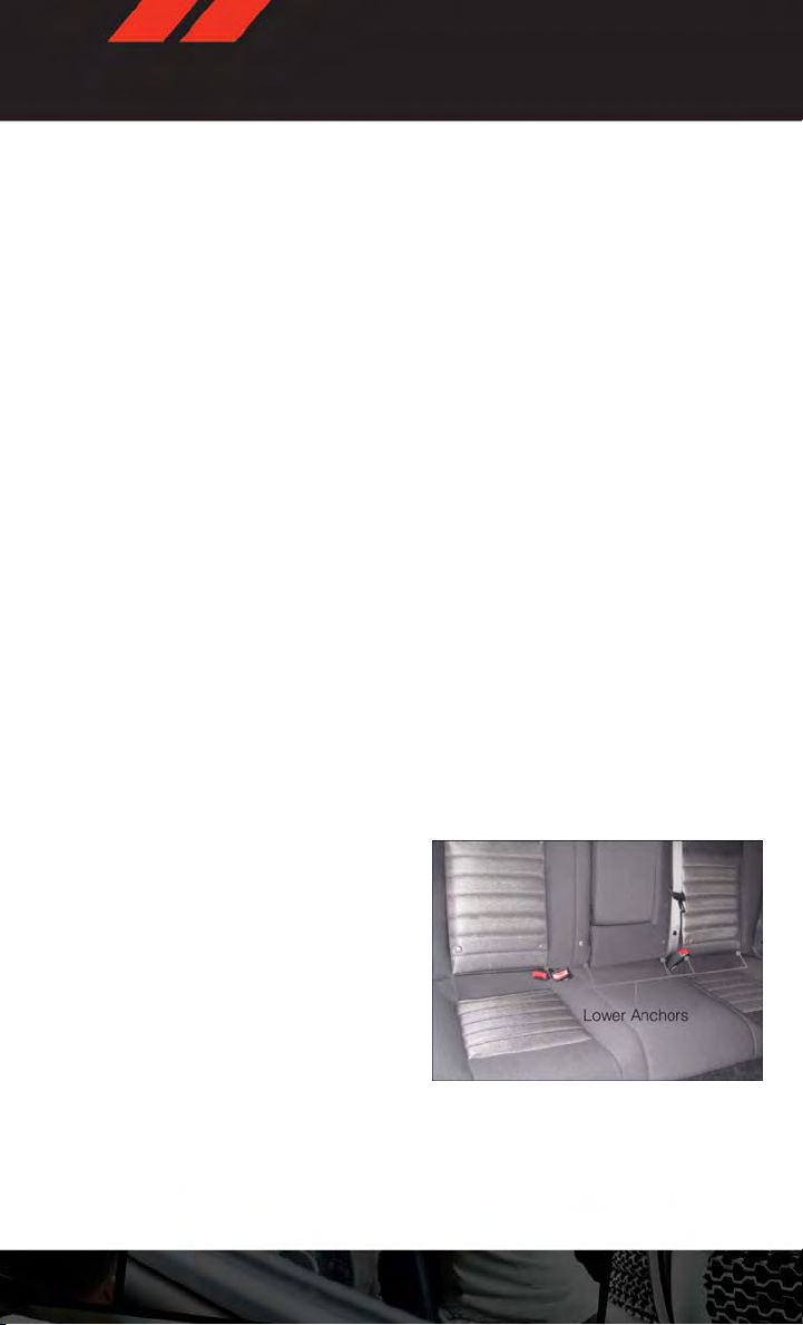
• The rear seat lower anchorages are round
bars, located at the rear of the seat cushion where it meets the seatback. They are
just visible when you lean into the rear
seat to install the child restraint. You will
easily feel them if you run your finger
along the intersection of the seatback
and seat cushion surfaces.
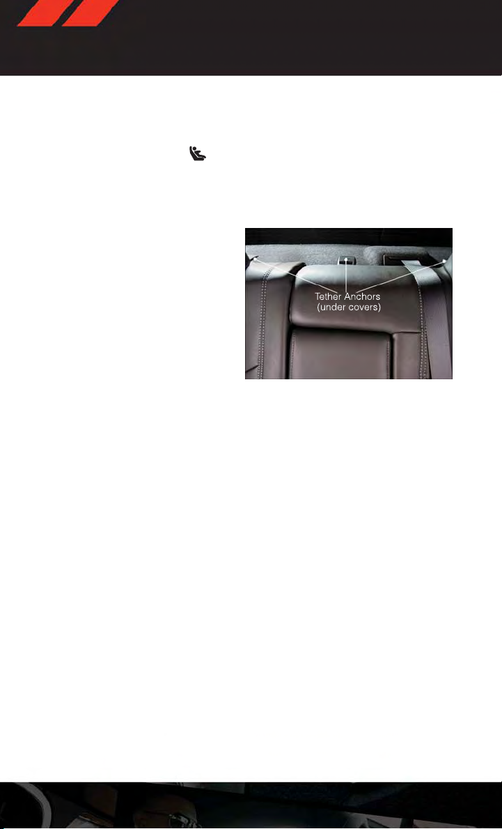
•Inaddition,therearetetherstrapanchorages behind each rear seating position
located in the panel between the rear
seatback and the rear window. These
tether strap anchorages are under a plastic cover.
•Loosenthechildseatadjustersonthelowerstrapsandtetherstrapssothatyoucan
attach the hook or connector to the lower and tether anchorages more easily.
17
Page 20
GETTING STARTED
•Attachthelowerhooksorconnectorsoverthetopoftheanchoragebars,pushingaside
the seat cover material. The rear seat lower anchorages are round bars, located at the
rear of the seat cushion where it meets the seatback. The rear seat lower anchors can be
readily identified by the symbol
ages and are just visible when you lean into the rear seat to install the child restraint.
• Then rotatethe tetheranchorage coverdirectly behind the seat whereyou areplacing the
child restraint and attach the tether strap to the anchorage, being careful to route the
tether strap to provide the most direct path between the anchor and the child restraint.
• Tighten all three straps as you push the
child restraint rearward and downward
into the seat.
Installing The Child Restraint Using The Vehicle Seat Belts
•Toinstallachildrestraint,first,pullenoughoftheseatbeltwebbingfromtheretractorto
route it through the belt path of the child restraint and slide the latch plate into the
buckle.
•Next,extractalltheseatbeltwebbingoutoftheretractorandthenallowthebeltto
retract into the retractor. Finally , pull on any excess webbing to tighten the lap portion
around the child restraint. Any seat belt system will loosen with time, so check the belt
occasionally, and pull it tight if necessary.
• Rotate the cover over the anchor directly behind the seat where you are placing the child
restraint. These tether strap anchorages are under a plastic cover.
•Routethetetherstraptoprovidethemostdirectpathforthestrapbetweentheanchor
and the child seat.
•Attachthetetherstraphookofthechildrestrainttotheanchorandremoveslackinthe
tether strap according to the child restraint manufacturer’s instructions.
located on the seatback directly above the anchor-
18
Page 21
GETTING STARTED
WARNING!
• In a collision, an unrestrained child, even a tiny baby, can become a projectile inside
the vehicle. The force required to hold even an infant on your lap could become so
great that you could not hold the child, no matter how strong you are. The child and
others could be severely injured or killed. Any child riding in your vehicle should be in
a proper restraint for the child's size.
• Rearward-facing child seats must never be used in the front seat of a vehicle with a
front passenger air bag. An air bag deployment could cause severe injury or death to
infants in this position.
•ImproperinstallationofachildrestrainttotheLATCHanchoragescanleadtofailure
of an infant or child restraint. The child could be severely injured or killed. Follow the
manufacturer’s directions exactly when installing an infant or child restraint.
•Anincorrectlyanchoredtetherstrapcouldleadtoincreasedheadmotionand
possible injury to the child. Use only the anchor positions directly behind the child
seat to secure a child restraint top tether strap.
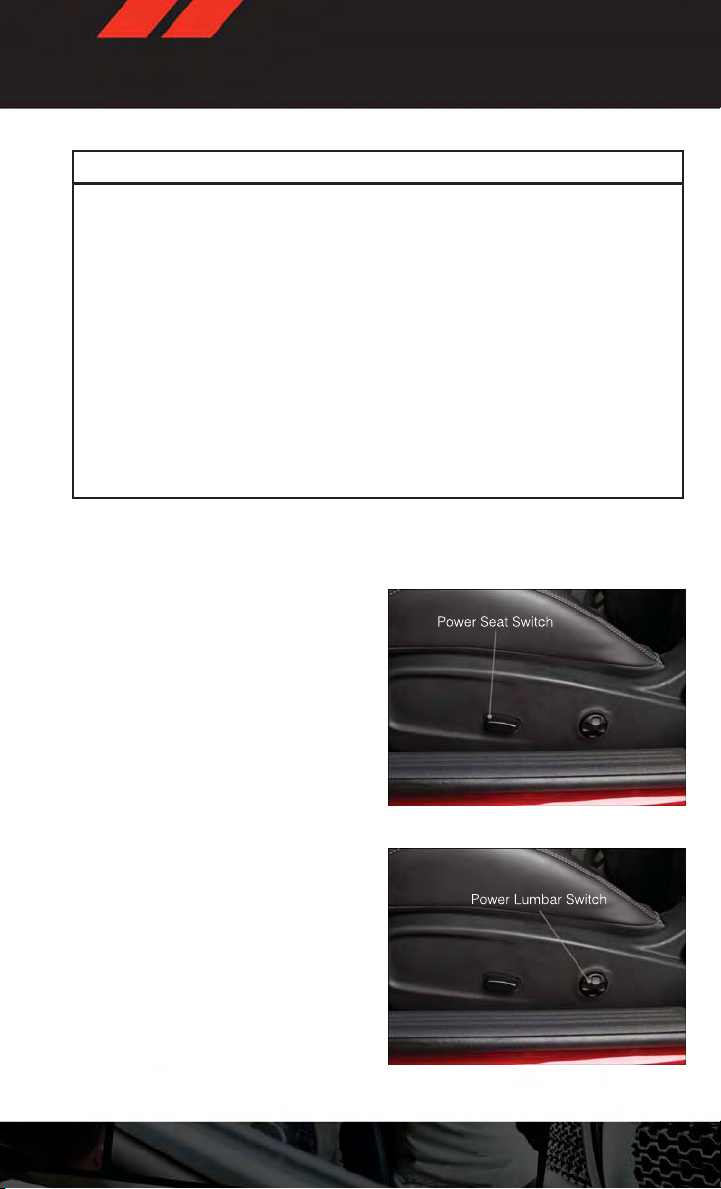
FRONT SEATS
Power Seats
•
The power seat switches are located on the
outboard side of the front seat cushions.
•
The seat switch, controls forward/
backward and up/down.
Power Lumbar
• Push the switch forward to increase the
lumbar support. Pushthe switch rearward
to decrease the lumbar support.
• Pushing upward or downward on the
switch will raise and lower the position of
the support.
19
Page 22
GETTING STARTED
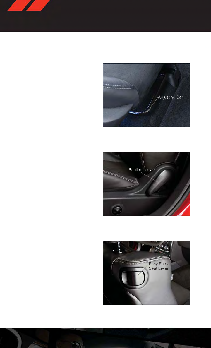
Manual Seat Adjustment
Forward/Rearward
• Lift up on the adjusting bar located at the
front of the seat near the floor and release
it when the seat is at the desired position.
Then, using body pressure, move forward
and backward on the seat to be sure that
the seat adjusters have latched.
Recliner
• Lean forward in the seat and lift the recliner lever, then lean back to the desired
position and release the lever.
•Liftthelevertoreturntheseatbacktoan
upright position.
Easy Entry Seats
• Pull forward on the lever, located on the
side of the seatback, to dump the seatback forward and slide the seat forward.
You can also temporarily remove the seat
belt from the guide loop on the seat and
allow the seat belt to retract out of the
way. This allows for easier access to the
rear seat.
20
Page 23
GETTING STARTED
CAUTION!
Do not place any article under a power seat or impede its ability to move as it may cause
damage to the seat controls.Seat travel may become limited if movement is stopped by
an obstruction in the seat's path.
WARNING!
•
Adjusting a seat while the vehicle is moving is dangerous. The sudden movement of the
seat could cause youto lose control. The seat belt mightnot be properly adjusted, and you
could be severely injured or killed. Only adjust a seat while the vehicle is parked.
• Do not ride with the seatback reclined so that the seat belt is no longer resting
against your chest. In a collision, you could slide under the seat belt and be severely
injured or killed. Use the recliner only when the vehicle is parked.
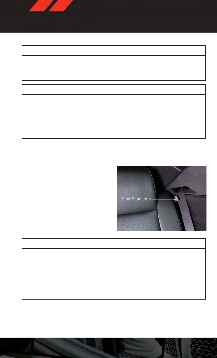
REAR SEAT
Folding Rear Seatback
• Pull on the loops, located near the outer
top of the seatbacks, to fold down either
or both seatbacks. These loops can be
tucked away when not in use.
•Whentheseatbackisraisedtotheupright
position, make sure it is latched by
strongly pulling on the top of the seatback
above the seat loop.
WARNING!
•Becertainthattheseatbackissecurelylockedintoposition.Iftheseatbackisnot
securely locked into position, the seat will not provide the proper stability for child
seats and/or passengers. An improperly latched seat could cause serious injury.
• The cargo area in the rear of the vehicle (with the rear seatbacks in the locked-up or
folded-down position) should not be used as a play area by children when the vehicle
is in motion.They could be seriously injured in a collision. Childrenshould be seated
and using the proper restraint system.
21
Page 24
GETTING STARTED
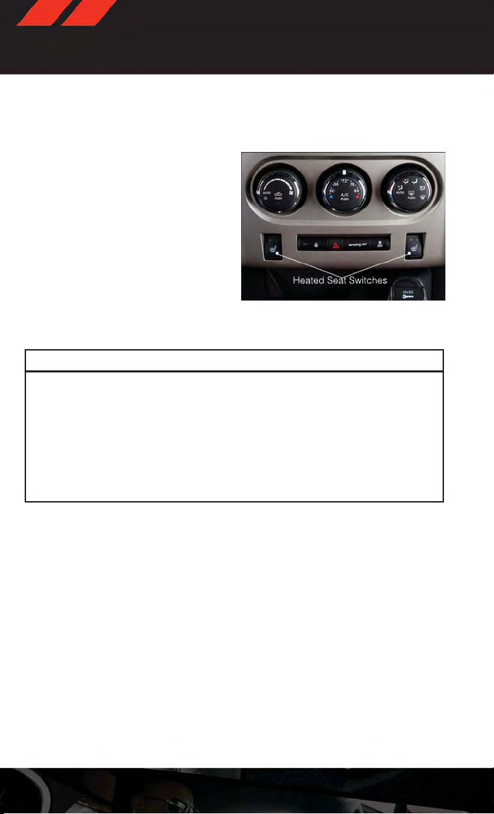
HEATED SEATS
Front Heated Seats
• The controls for front heated seats are
located on the center instrument panel
below the climate controls.
•PresstheswitchoncetoselectHigh-level
heating. Press the switch a second time
to select Low-level heating. Press the
switch a third time to shut the heating
elements Off.
• If the High-level setting is selected, the
system will automatically switch to Lowlevel after approximately 60 minutes. The
Low-level setting will turn Off automatically after approximately 45 minutes.
WARNING!
•Personswhoareunabletofeelpaintotheskinbecauseofadvancedage,chronic
illness, diabetes, spinal cord injury, medication, alcohol use, exhaustion or other
physical conditions must exercise care when using the seat heater. It may cause
burns even at low temperatures, especially if used for long periods of time.
• Do not place anything on the seat that insulates against heat, such as a blanket or
cushion. This may cause the seat heater to overheat. Sitting in a seat that has been
overheated could cause serious burns due to the increased surface temperature of
the seat.
22
Page 25
GETTING STARTED
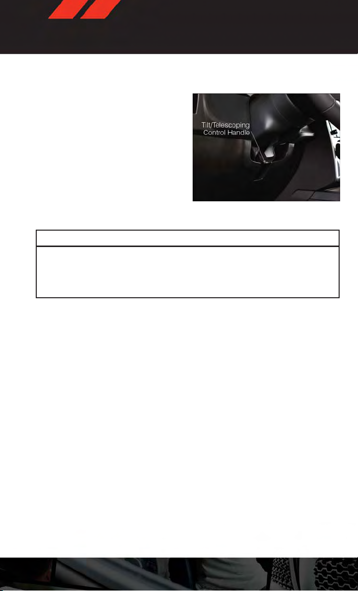
TILT/TELESCOPING STEERING COLUMN
• The tilt/telescoping control handle is located below the steering wheel at the end
of the steering column.
• To unlock the steering column, push the
lever downward (toward the floor).
• To tilt the steering column, move the
steering wheel upward or downward as
desired. To lengthen or shorten the steering column, pull the steering wheel outward or push it inward as desired.
• To lock the steering column in position,
push the lever upward until fully engaged.
WARNING!
Do not adjust the steering wheel while driving. The tilt/telescoping adjustment must be
locked while driving. Adjusting the steering wheel while driving or driving without the
tilt/telescoping adjustment locked could cause the driver to lose control of the vehicle.
Failure to follow this warning may result in you and others being severely injured or killed.
23
Page 26
OPERATING YOUR VEHICLE
ENGINE BREAK-IN RECOMMENDATIONS
• A long break-in period is not requiredfor thedrivetrain (engine, transmission, clutch, and
rear axle) in your new vehicle.
•Drivemoderatelyduringthefirst500mi(800km).Aftertheinitial60mi(100km),speeds
up to 50 or 55 mph (80 or 90 km/h) are desirable.
• While cruising, brief full-throttle acceleration within the limits of local traffic laws
contributes to a good break-in. However, wide-open throttle acceleration in low gear can
be detrimental and should be avoided.
•Theengineoil,transmissionfluid,andaxlelubricantinstalledatthefactoryishighquality and energy-conserving. Oil, fluid, and lubricant changes should be consistent
with anticipated climate and conditions under which vehicle operations will occur. For
the recommended viscosity and quality grades, refer to “Maintaining Your Vehicle”.
NOTE:
Anewenginemayconsumesomeoilduringitsfirstfewthousandmiles(kilometers)of
operation. This should be considered a normal part of the break-in and not interpretedas an
indication of difficulty.
CAUTION!
Never use Non-Detergent Oil or Straight Mineral Oil in the engine or damage may result.
Engine Break-In Recommendation — SRT8 Version
• A long break-in period is not required for the drivetrain (engine, transmission, and rear
axle) in your new vehicle.
•Drivemoderatelyduringthefirst500miles(800km).Aftertheinitial60miles(100km),
speeds up to 50 or 55 mph (80 or 90 km/h) are desirable.
• While cruising, brief full-throttle acceleration within the limits of local traffic laws
contributes to a good break-in. However, wide-open throttle acceleration in low gear can
be detrimental and should be avoided.
•Theengineoilisahighperformancesyntheticlubricant,thetransmissionfluid,andaxle
lubricant installed at the factory is high-quality and energy-conserving. Oil, fluid, and
lubricant changes should be consistent with anticipated climate and conditions under
which vehicle operations will occur. For the recommended viscosity and quality grades,
refer to “Maintaining Your Vehicle”.
NOTE:
Anewenginemayconsumesomeoilduringitsfirstfewthousandmiles(kilometers)of
operation. This should be considered a normal part of the break-in and not interpretedas an
indication of difficulty.
CAUTION!
Never use Non-Detergent Oil or Straight Mineral Oil in the engine or damage may result.
24
Page 27
OPERATING YOUR VEHICLE
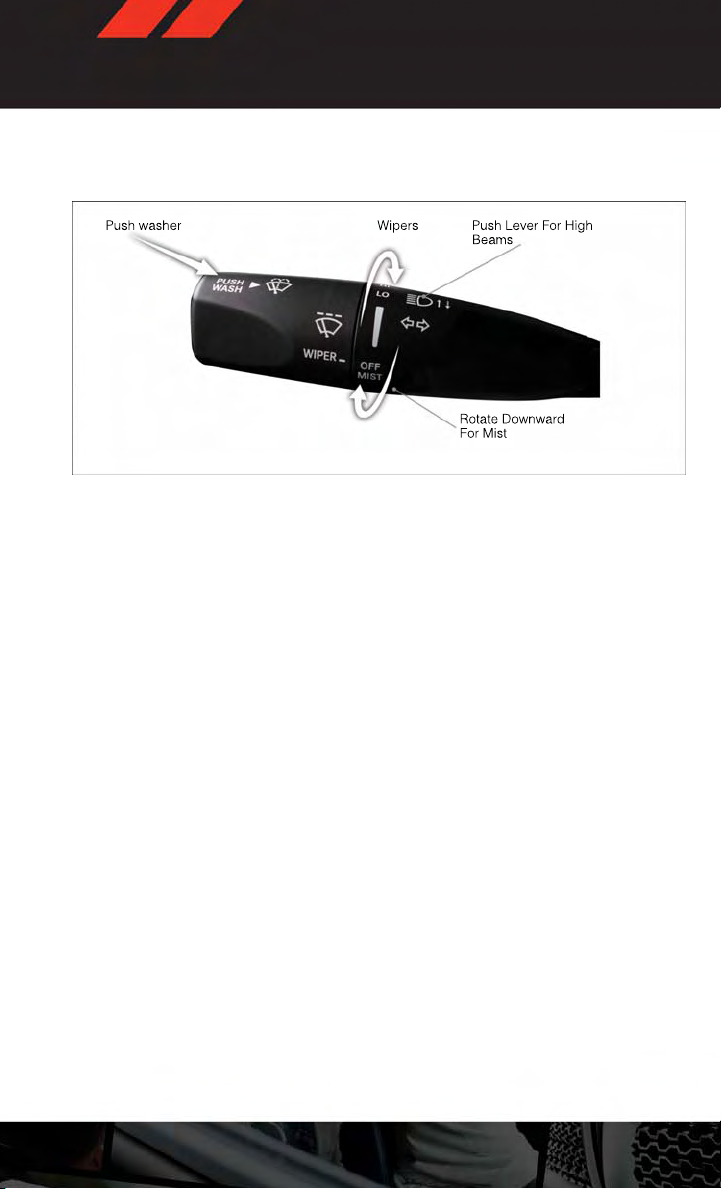
TURN SIGNAL/WIPER/WASHER/HIGH BEAM LEVER
Turn Signal/Lane Change Assist
• Tap the lever up or down once and the turn signal (right or left) will flash three times and
automatically turn off.
Front Wipers
Intermittent, Low And High Operation
•Rotatetheendofthelevertothefirstdetentpositionforoneoffiveintermittentsettings,
the second detent for low wiper operation and the third detent for high wiper operation.
Mist
• Rotate the end of the lever downward when a single wipe is desired.
NOTE:
The mist feature does not activate the washer pump; therefore, no washer fluid will be
sprayed on the windshield. The wash function must be activated in order to spray the
windshield with washer fluid.
Washer Operation
• Push the end of the lever inward and hold for as long as spray is desired.
High Beam Operation
•Pushtheleverforwardtoactivatethehighbeams.Pullthelevertowardyouforflashto
pass.
NOTE:
For safe driving, turn off the high beams when oncoming traffic is present to prevent
headlight glare and as a courtesy to other motorists.
25
Page 28
OPERATING YOUR VEHICLE
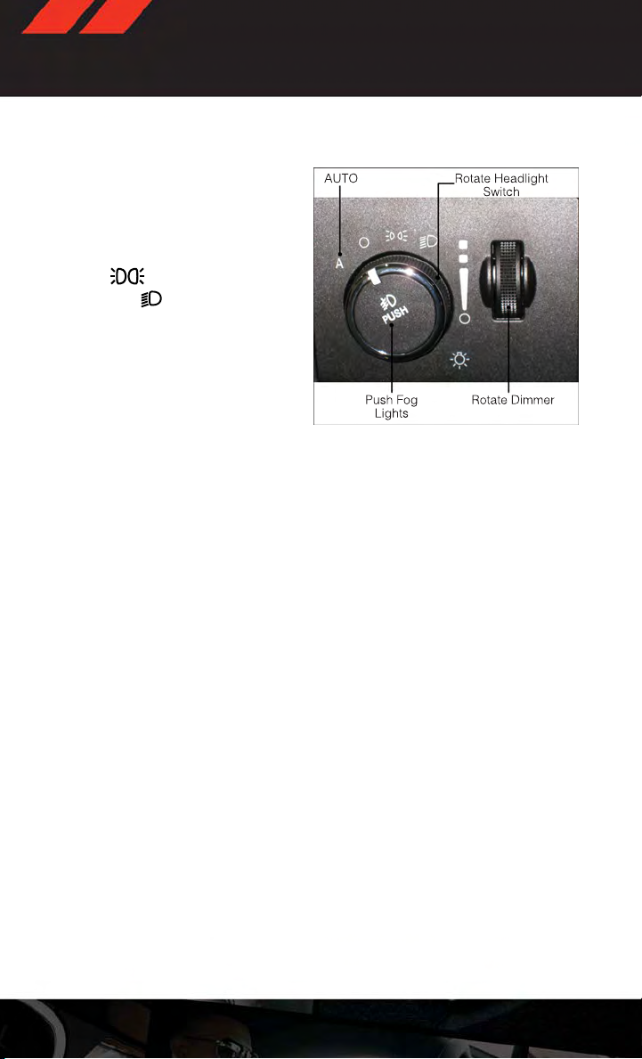
HEADLIGHT SWITCH
Automatic Headlights/Parking Lights/Headlights
• Rotate the headlight switch, located on
the instrument panel to the left of the
steering wheel, to thefirst detentfor park-
ing lights
for headlights
• With the parking lights or low beam headlights on, push the headlight switch once
for fog lights.
•Rotatetheheadlightswitchto“A”for
AUTO headlights.
•Whensetto“A”(AUTO),thesystemautomatically turns the headlights on or off
based on ambient light levels.
Fog Lights
•Turntheheadlightsorparkinglightsonandpushtheheadlightswitchoncetoturnthe
fog lights on. Push the switch a second time to turn the fog lights off. Fog lights will not
operate when high beams are on.
•Afoglightsymbolwillilluminateintheclustertoindicatethefoglightsareon.
Instrument Panel Dimmer
•Rotatethedimmercontroltotheextremebottompositiontofullydimtheinstrument
panel lights and prevent the interior lights from illuminating when a door is opened.
•Rotatethedimmercontroluptoincreasethebrightnessoftheinstrumentpanelwhen
the parking lights or headlights are on.
•Rotatethedimmercontroluptothenextdetentpositiontofullybrightentheodometer
and radio when the parking lights or headlights are on. Refer to your Uconnect®/Radio
User Manual on the DVD for display dimming.
•Rotatethedimmercontroluptothelastdetentpositiontoturnontheinteriorlighting.
and to the seconddetent
.
26
Page 29
OPERATING YOUR VEHICLE
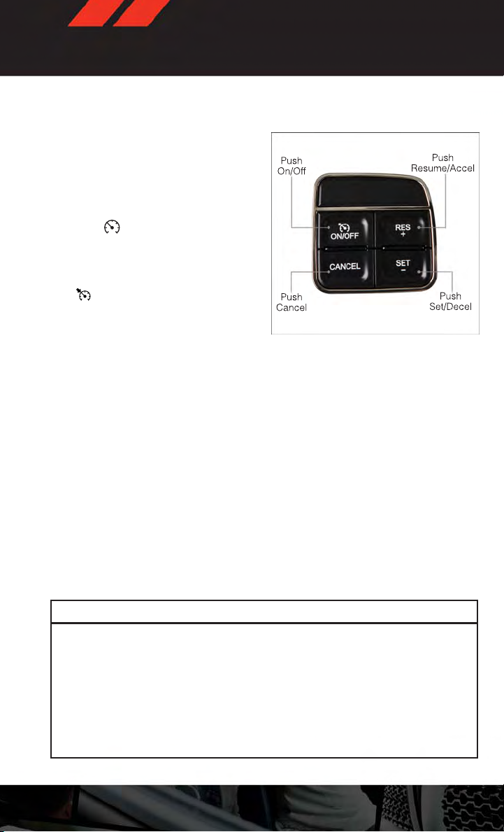
SPEED CONTROL
• The Speed Control switches are located
on the steering wheel.
Cruise ON/OFF
•PushtheON/OFFbuttontoactivatethe
Speed Control.
CRUISE will appear on the instrument
•
cluster to indicate the Speed Control is on.
•PushtheON/OFFbuttonasecondtimeto
turn the system off.
SET
•
With theSpeed Control on, push and release
the SET – button to set a desired speed.
Accel/Decel
•Onceaspeedisset,pushingtheRES+buttononceortheSET–buttononcewillincrease
or decrease the set speed approximately 1 mph (2 km/h).
•PushandholdtheRES+buttontoacceleratein5mph(8km/h)incrementsorpushand
hold the SET – button to decelerate in 5 mph (8 km/h) increments; release the button to
save the new set speed.
Resume
•Toresumeapreviouslyselectedsetspeedinmemory,pushtheRES+buttonand
release.
Cancel
•PushtheCANCELbutton,orapplythebrakestocancelthesetspeedandmaintainthe
set speed memory.
•PushtheON/OFFbuttontoturnthesystemoffanderasethesetspeedmemory.
WARNING!
•LeavingtheElectronicSpeedControlsystemonwhennotinuseisdangerous.You
could accidentally set the system or cause it to go faster than you want. You could
lose control and have a collision. Always leave the Electronic Speed Control system
off when you are not using it.
•ElectronicSpeedControlcanbedangerouswherethesystemcannotmaintaina
constant speed. Your vehicle could go too fastfor the conditions, and you could lose
control. A collision could be the result. Do not use Electronic Speed Control in heavy
traffic or on roads that are winding, icy, snow-covered or slippery.
27
Page 30
OPERATING YOUR VEHICLE
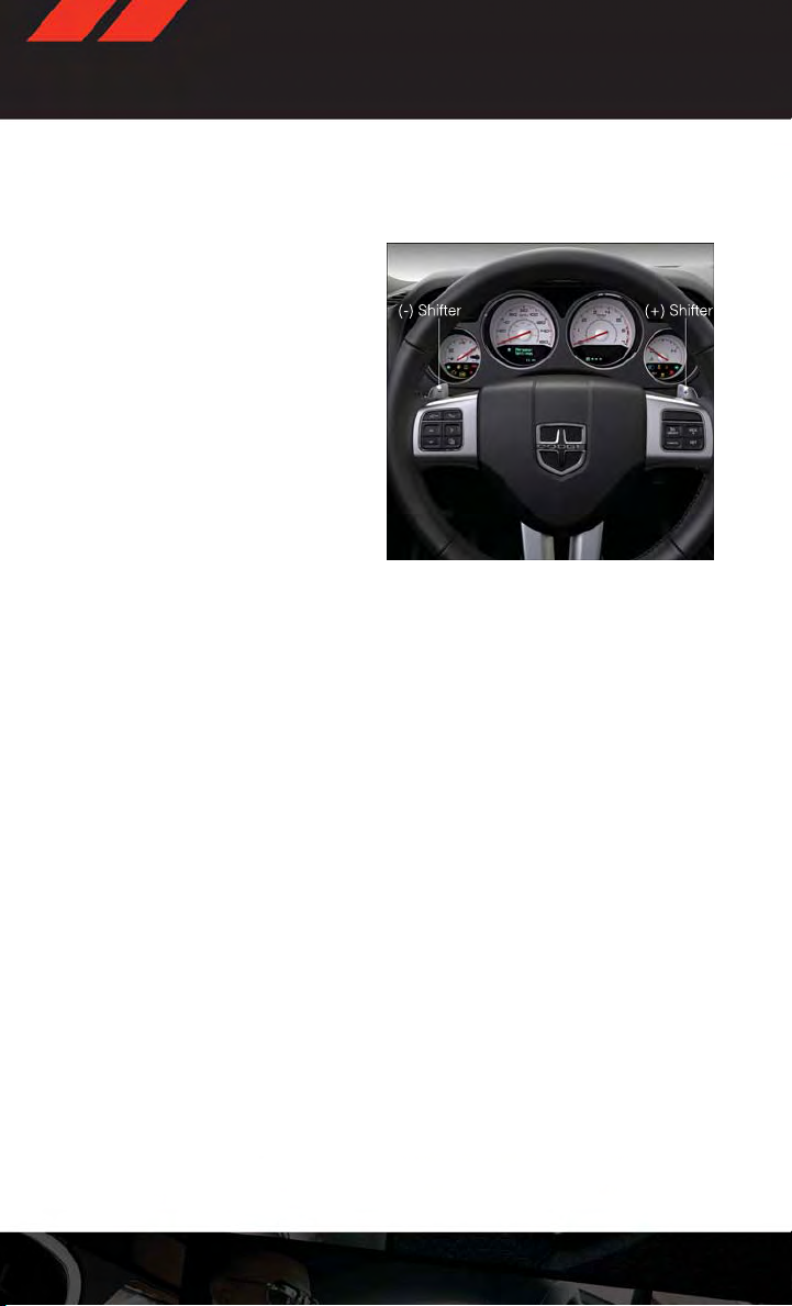
AUTOSTICK®
Steering Wheel Mounted Paddle Shifters Or Console Mounted Shifter
•AutoStick®isadriver-interactivetransmission feature that offers manual gear
shifting to provide you with more control
of the vehicle. AutoStick® allows you to
maximize engine braking, and improve
overall vehicle performance.
This system can also provide you with more
•
control during passing, city driving, cold
slippery conditions, mountain driving,
trailer towing, and many other situations.
Operation
• When the shift lever is in the DRIVE position, the transmission will operate automatically, shifting between the five available gears. To engage AutoStick®, simply
move the shift lever to the right or left (+/-) while in the DRIVE position, orpress one of the
steering wheel mounted shift paddles (+/-). When AutoStick® is active, the current
transmission gear is displayed in the Electronic Vehicle Information Center (EVIC) portion of the instrument cluster. In AutoStick® mode, the transmission will shift when
manually selected by the driver (using the shift lever, or the shift paddles), unless an
engine lugging or overspeed condition would result. It will remain in the selected gear
until another upshift or downshift is chosen, except as described below:
•Thetransmissionwillautomaticallydownshiftasthevehicleslows(topreventengine
lugging) and will display the current gear.
•Thetransmissionwillautomaticallydownshifttofirstgearwhencomingtoastop.
•Youcanstartoutinfirstorsecondgear.Tapping(+)(atastop)willallowstartingin
second gear. Starting out in second gear is helpful in snowy or icy conditions.
•Thesystemwillignoreattemptstoupshiftattoolowofavehiclespeed.
•TransmissionshiftingwillbemorenoticeablewhenAutoStick®isengaged.Todisengage AutoStick® mode, hold the shift lever to the right or press and hold the (+) shift
paddle until “D” is once again displayed in the instrument cluster. You can shift in or
out of the AutoStick® mode at any time without taking your foot off the accelerator
pedal.
28
Page 31

OPERATING YOUR VEHICLE
SPORT MODE – IF EQUIPPED
•Thismodealtersthetransmission'sautomaticshiftscheduleforsportierdriving.Upshift
speeds are increased to make full use of available engine power. Sport Mode is enabled/
disable by pressing the sport mode button on the center instrument panel below the
climate controls. When SPORT mode is enabled, a “SPORT” message will display in the
instrument cluster.
MANUAL TRANSMISSION 1 TO 4 SKIP SHIFT
• Skip Shift is enabled when vehicle speed is between 19 MPH (30 km/h) and 21 MPH
(34 km/h) and the accelerator pedal is at 1/4 throttle or less.
• For optimal fuel economy, under low acceleration conditions, your vehicle will only allow
you to shift from first gear to fourth gear. Additionally, the skip shift message will appear
on the Electronic Vehicle Information Center.
•RefertoyourOwner'sManualontheDVDforfurtherinformation.
29
Page 32

OPERATING YOUR VEHICLE
MANUAL CLIMATE CONTROLS
Air Recirculation
• Use Recirculation for maximum A/C operation.
•Forwindowdefogging,turntherecirculationbuttonoff.
• Recirculation is allowed in floor mode.
• Recirculation is allowed in defrost/floor (mix modes) for approximately five minutes.
Heated Mirrors
•Themirrorsareheatedtomeltfrostorice.Thisfeatureisactivatedwheneveryouturnon
the rear window defroster.
30
Page 33

OPERATING YOUR VEHICLE
AUTOMATIC TEMPERATURE CONTROLS (ATC)
Automatic Operation
•TurntheModeandBlowerControlstotheAUTOposition.
• Select the desired temperature by rotating the Temperature Control.
•Thesystemwillmaintainthesettemperatureautomatically.
Air Conditioning (A/C)
•IftheairconditioningbuttonispressedwhileintheAUTOmode,theindicatorlightmay
flash three times to indicate the cabin air is being controlled automatically.
Air Recirculation
• Use Recirculation for maximum A/C operation.
•Forwindowdefogging,turntherecirculationbuttonoff.
•IftherecirculationbuttonispressedwhileintheAUTOmode,theindicatorlightmay
flash three times to indicate the cabin air is being controlled automatically.
Heated Mirrors
•Themirrorsareheatedtomeltfrostorice.Thisfeatureisactivatedwheneveryouturnon
the rear window defroster.
31
Page 34

OPERATING YOUR VEHICLE
POWER SUNROOF
• The power sunroof switch is located on the overhead console.
Opening Sunroof
Express
•Presstheswitchrearwardandrelease.Thesunroofwillfullyopenandstopautomatically.
Closing Sunroof
Express
•Presstheswitchforwardandrelease.Thesunroofwillcloseautomaticallyfromany
position.
Manual Open/Close
•Pressandholdtheswitchrearwardtoopenorforwardtoclosethesunroof.Anyrelease
of the switch will stop the movement, and the sunroof will remain in a partially open or
closed position until the switch is pressed again.
Venting Sunroof
•Pressandreleasethe"VENT"button,andthesunroofwillopentotheventposition.This
is called “Express Vent” and will occur regardless of sunroof position. During Express
Ven t operat ion, a ny movem ent of the switc h wi ll stop t he sunro of.
Pinch Protection Feature
• This featurewill detectan obstructionin the opening of the sunroof during Express Close
operation. If an obstruction in the path of the sunroof is detected, the sunroof will
automatically retract. Remove the obstruction if this occurs. Next, press the switch
forward and release to Express Close.
NOTE:
If three consecutive sunroof close attempts result in Pinch Protect reversals, the fourth
close attempt will be a Manual Close movement with Pinch Protect disabled.
WARNING!
•Neverleavechildrenunattendedinavehicle,anddonotleavethekeyintheignition
switch (or leave the ignition of a vehicle equipped with Keyless Enter-N-Go™ in the
ACC or ON/Run mode). Occupants, particularly unattended children, can become
entrapped by the power sunroof while operating the power sunroof switch. Such
entrapment may result in serious injury or death.
• In a collision, there is a greater risk of being thrown from a vehicle with an open
sunroof. You could also be severely injured or killed. Always fasten your seat belt
properly and make sure all passengers are properly secured.
•Donotallowsmallchildrentooperatethesunroof.Neverallowyourfingers,other
body parts, or any object to project through the sunroof opening. Injury may result.
32
Page 35

OPERATING YOUR VEHICLE
WIND BUFFETING
•Windbuffetingcanbedescribedasahelicopter-typepercussionsound.Ifbuffeting
occurs with the windows open, adjust the windows together.
•Ifbuffetingoccurswiththesunroofopen,adjustthesunroofopening,oradjustany
window. This will minimize buffeting.
33
Page 36

ELECTRONICS
YOUR VEHICLE'S SOUND SYSTEM
34
Page 37

ELECTRONICS
35
Page 38

ELECTRONICS
Uconnect® 130
NOTE:
Your r a d i o has m a n y features t h a t add t o the comfo r t and c o n v e n i e n c e of y o u and y o u r
passengers. Some of these radio features should not be used when driving because they
take your eyes from the road or your attention from driving.
Clock Setting
•Pressandholdthe“TIME”buttonuntilthehoursblink;turnthe“TUNE/SCROLL”control
knob to set the hours.
•Pressthe“TUNE/SCROLL”controlknobuntiltheminutesbegintoblink;turnthe“TUNE/
SCROLL” control knob to set the minutes.
•Pressthe“TUNE/SCROLL”controlknobtosavethetimechange.
•Toexit,pressanybutton/knoborwaitfiveseconds.
Equalizer, Balance And Fade
•Pressthe“TUNE/SCROLL”controlknobandBASS,MID,TREBLE,BALANCEandFADEwill
display. Rotate the “TUNE/SCROLL” control knob to select the desired setting.
36
Page 39

ELECTRONICS
Radio Operation
Seek Up/Down Buttons
•PresstoseekthroughradiostationsinAMorFMbands.
•Holdeitherbuttontobypassstationswithoutstopping.
Store Radio Presets
•Pressthe“SET/RND”buttononceandSET1willshowinthedisplay.Thenselectbutton
(1–6).
•Asecondstationmaybeaddedtoeachpushbutton.Pressthe“SET/RND”buttontwice
and SET 2 will show in the display. Then select button (1–6).
CD/DISC Operation
Seek Up/Down Buttons
•PresstoseekthroughCDtracks.
•Holdeitherbuttontobypasstrackswithoutstopping.
SET/RND Button (Random Play)
•PressthisbuttonwhiletheCDisplayingtoactivateRandomPlay.
•ThisfeatureplaystheselectionsontheCDinrandomordertoprovideaninteresting
change of pace.
Audio Jack Operation
•TheAUX/AudioJackprovidesameanstoconnectaportableaudiodevice,suchasan
MP3 player or an iPod®, to the vehicles sound system. This requires the use of a 3.5 mm
stereo audio patch cable.
•PressingtheAUXbuttonwillchangethemodetoauxiliarydeviceiftheAudioJackis
connected, allowing the music from your portable device to play through the vehicle's
speakers.
•Thefunctionsoftheportabledevicearecontrolledusingthedevicebuttons,notthe
buttons on the radio. However, the volume may be controlled using the radio or portable
device.
37
Page 40

ELECTRONICS
Uconnect® 130 WITH SiriusXM SATELLITE RADIO
NOTE:
• Your radio may not be equipped with the Uconnect® Voice Command and Uconnect®
Phone features.To determine if yourradio has these features, pressthe Voice Command
button on the radio.You willhear avoice promptif youhave thefeature, or see amessage
on the radio stating “Uconnect Phone not available” if you do not.
•Yourradiohasmanyfeaturesthataddtothecomfortandconvenienceofyouandyour
passengers. Someof these radio features should not beused when driving because they
take your eyes from the road or your attention from driving.
Clock Setting
•Pressandholdthe“TIME”buttonuntilthehoursblink;turnthe“TUNE/SCROLL”control
knob to set the hours.
•Pressthe“TUNE/SCROLL”controlknobuntiltheminutesbegintoblink;turnthe“TUNE/
SCROLL” control knob to set the minutes.
•Pressthe“TUNE/SCROLL”controlknobtosavethetimechange.
•Toexit,pressanybutton/knoborwaitfiveseconds.
Equalizer, Balance And Fade
•Pressthe“TUNE/SCROLL”controlknobandBASS,MID,TREBLE,BALANCEandFADEwill
display. Rotate the “TUNE/SCROLL” control knob to select the desired setting.
38
Page 41

ELECTRONICS
Radio Operation
Seek Up/Down Buttons
•PresstoseekthroughradiostationsinAM,FM,orSATbands.
•Holdeitherbuttontobypassstationswithoutstopping.
Store Radio Presets
•Pressthe“SET/RND”buttononceandSET1willshowinthedisplay.Thenselectbutton
(1–6).
•Asecondstationmaybeaddedtoeachpushbutton.Pressthe“SET/RND”buttontwice
and SET 2 will show in the display. Then select button (1–6).
Music Type
•Pressthe“MUSICTYPE”buttontoactivatethismode.Pressthe“MUSICTYPE”button
again or turn the “TUNE/SCROLL” control knob to select the desired music type (Adult
Hits, Country, Jazz, Oldies, Rock, etc.).
•Onceamusictypeischosenandtheiconisdisplayed,presseither“SEEK”buttonand
the radio will only search for stations with the selected music type.
NOTE:
The Music Type function only operates when in FM mode.
SETUP Button
•Pressingthe“SETUP”buttonallowsyoutoselectbetweenitemsthatareavailableinthat
particular mode.
•Turnthe“TUNE/SCROLL”controlknobtoscrollthroughtheentries.Pushthe“AUDIO/
SELECT” button to select an entry and make changes.
SiriusXM Satellite Radio
• SiriusXM Satellite Radio gives you over 130 channels, including 100% commercial-free
music from nearly every genre, plus all your favorite sports, news, talk andentertainment
channels–all with crystal clear, coast-to-coast coverage, all in one place and all at your
fingertips.
• To access SiriusXM Satellite Radio, press the “SAT” hard-key.
CD/DISC Operation
Seek Up/Down Buttons
•PresstoseekthroughCDtracks.
•Holdeitherbuttontobypasstrackswithoutstopping.
SET/RND Button (Random Play)
•PressthisbuttonwhiletheCDisplayingtoactivateRandomPlay.
•ThisfeatureplaystheselectionsontheCDinrandomordertoprovideaninteresting
change of pace.
39
Page 42

ELECTRONICS
LIST Button
•Pressthe“LIST”buttontobringupalistofallfoldersontheCD.Scrollupordownthelist
by turning the “TUNE/SCROLL” control knob.
• To select a folder from the list, press the “TUNE/SCROLL” control knob and the radio will
begin playing the files contained in that folder.
Audio Jack Operation
•TheAUX/AudioJackprovidesameanstoconnectaportableaudiodevice,suchasan
MP3 player or an iPod®, to the vehicles sound system. This requires the use of a 3.5 mm
stereo audio patch cable.
•PressingtheAUXbuttonwillchangethemodetoauxiliarydeviceiftheAudioJackis
connected, allowing the music from your portable device to play through the vehicle's
speakers.
The functions of the portable device are controlled using the device buttons, not the buttons
•
on the radio. However, the volume may be controlled using the radio or portable device.
Uconnect® 430/430N
NOTE:
• Your radio may not be equipped with the Uconnect® Voice Command and Uconnect®
Phone features.To determine if yourradio has these features, pressthe Voice Command
button on the radio.You willhear avoice promptif youhave thefeature, or see amessage
on the radio stating “Uconnect Phone not available” if you do not.
40
Page 43

ELECTRONICS
•Yourradiohasmanyfeaturesthataddtothecomfortandconvenienceofyouandyour
passengers. Someof these radio features should not beused when driving because they
take your eyes from the road or your attention from driving.
Clock Setting
•Turntheradioon,thentouchthescreenwherethetimeisdisplayed.
•Touchthe“USERCLOCK”soft-key(Navigationradioonly).
•Toadjustthehours,toucheitherthe“HOURFORWARD”or“HOURBACKWARD”soft-key.
•Toadjusttheminutes,toucheitherthe“MINUTEFORWARD”or“MINUTEBACKWARD”
soft-key.
•Tosavethenewtimesetting,touchthescreenwheretheword“Save”isdisplayed.
Menu
•Pressthe“MENU”hard-keytoaccesstheSystemSetupmenuandtheMyFilesmenu.
•Pressthe“MENU”hard-keyinanactivemode(SAT,CD,AUX,etc.)tochangemode
specific settings.
Equalizer, Balance And Fade
Audio Control Menu
• Press the “AUDIO” hard-key on the right
side of the radio.
• Use either the arrow soft-keys or the
cross-hair on the screen to change Balance and Fade. The “CENTER” soft-key
resets the settings.
Touch the “Equalizer” soft-key and use ei-
•
ther the arrow soft-keys or the sliders on the
screen to adjust BASS, MID, and/or TREBLE.
Display Settings
•Pressthe“MENU”hard-keyandtouchthe
“Display Settings” soft-key to access the
Display Settings menu.
•Selectthe“DaytimeColors”soft-keyto
switch to manual daytime mode and to
adjust the brightness of the display using
daytime colors.
•Selectthe“NighttimeColors”soft-keyto
switch to manual nighttime mode and to
adjust the brightness of the display using nighttime colors.
•Selectthe“AutoColorMode”soft-keytoswitchtoautomaticdaytime/nighttimemode
and to control the brightness of the display using the dimmer switch of the vehicle.
•Touchthe“EXIT”soft-keytosaveyoursettings.
41
Page 44

ELECTRONICS
Radio Operation
•ToaccessRadioMode,touchthe“RADIO”hard-keyontheleftsideofthefaceplate,then
touch the “AM,” “FM” or “SAT” soft-key at the top of the screen to select the band.
Seek Up/Seek Down
• Press the “Seek Up” or “Seek Down” soft-keys to seek through radio stations in AM, FM,
or SAT bands. Hold either Seek to bypass stations without stopping.
Store Radio Presets
•Selecttheradiobandbytouchingeitherthe“AM,”“FM,”or“SAT”soft-key.
•Findthestationtostorebyeitherpressingthe“SeekUp”or“SeekDown”soft-keys,
touching the “SCAN” soft-key, or by using the “DIRECT TUNE” soft-key.
•Oncethestationisfound,touchandholdoneofthe“PRESET”soft-keysinthelisttothe
right, until you hear a confirmation beep.
NOTE:
If the Presets are not visible on the right side of the screen, press the “Presets” soft-key.
42
Page 45

ELECTRONICS
CD/DVD Disc Operation
•Pressthe“MEDIA”hardkeytodisplaythemediasourcetabsatthetopofthescreen.
Select the source by touching the “HDD,” “DISC,” or “AUX” media source soft-key tab.
NOTE:
Your Tou c h - S c r e e n R a d i o w i l l u s u ally aut o m a t i c a l l y s w i t c h t o t h e a p propriate mo d e w h e n
something is first connected or inserted into the system.
Insert a CD/DVD Disc
• To insert a disc, press the “LOAD” hard-key.
•Withtheprintedsideupwards,insertthediscintothediscslotoftheradio.Theradio
pulls the disc in automatically and closes the flip screen. The radio selects the appropriate mode after the disc is recognized, and starts playing the first track. The display
shows “Reading...” during this process.
Seek Up/Seek Down
• Press the “Seek Up” or “Seek Down” soft-keys to seek through tracks in Disc Mode. Hold
either Seek to bypass tracks without stopping.
Audio Jack Operation
•TheAUX/AudioJackprovidesameanstoconnectaportableaudiodevice,suchasan
MP3 player or an iPod®, to the vehicles sound system. This requires the use of a 3.5 mm
stereo audio patch cable.
43
Page 46

ELECTRONICS
•Pressthe“MEDIA”hard-keythenthe“AUX”soft-keytochangethemodetoauxiliary
device if the Audio Jack is connected, allowing the music from your portable device to
play through the vehicle's speakers.
• The functions of the portable device are controlled using the device itself, not the
buttons on the radio. However, the volume may be controlled using the radio or portable
device.
Hard Disk Drive (HDD) Operation
•TheHardDiskDrive(HDD)modegivesyouaccesstotheaudiofilesontheinternalhard
disk drive.It functions similar to aCD player, with the exception that the internal HDD can
hold more tracks.
•Itisalsopossibletoimportdisplaypicturestotheinternalharddiskdrive.Thepictures
can be displayed on the right half of the radio screen.
•BeforeusingtheHDDmode,youwillneedtocopysongsandpicturestotheinternalhard
drive. Songs and picturescan be added to the hard driveby usinga CD or USB device(e.g.
thumb drive or memory stick).
NOTE:
•HDDsupportsonly.jpg/JPEGformatsforphotos.
•WMA/MP3FilesandSelectiveSongsfromaCDcanalsobeaddedtotheHDD.Seethe
Uconnect® 430/430N User's Manual for more information.
Copying Music From CD
• Press the “LOAD” hard-key.
• Insert a disc, then press the “MY FILES” hard-key and then select “MY MUSIC” soft-key.
•Touchthe“AddMusicFilestoHDD”soft-key,thentouchthe“Disc”soft-keyinthenext
screen to start the process.
NOTE:
•Youmightneedtoselectthefolderortitle
depending on the CD, then press “DONE”
to start the copy process.
• The copy progress is shown in the lower
left corner of the screen.
44
Page 47

ELECTRONICS
Copying Music From USB
•TheUSBportontheradiofaceplateallowsyoutocopyfilestoyourharddrive.Toaccess,
lift up on the cover.
• Insert a USB device (e.g.thumb drive or memory stick), then select “MY MUSIC soft-key.”
•Touchthe“AddMusicFilestoHDD”soft-key,thentouchthe“FrontUSB”soft-keyinthe
next screen.
•Selectthefoldersortitlesyouwouldlike
to copy, then touch the “DONE” soft-key
to start the copy process.
NOTE:
The copy progress is shown in the lower left
corner of the screen.
Copying Pictures To The HDD
• Insert either a CD or a USB device containing your pictures in JPEG format.
• Press the “MY FILES” hard-key.
•Touchthe“MyPictures”soft-keytogetanoverviewofthecurrentlystoredimages,then
touch the “Add” soft-key.
•Touchthe“Disc”or“USB”soft-key,thenselectthefoldersorpicturesyouwishtocopyto
the HDD. Use the “PAGE” soft-keys to page through the list of pictures.
• Touch the desired pictures or press the “All” soft-key for all pictures. Confirm your
selections by touching the “SAVE” soft-key.
NOTE:
The copy progress is shown in the lower left
corner of the screen.
Display A Picture On The Radio Screen
•Oncetheimportiscomplete,thepictureswillthenbeavailableinthe“MYPICTURES”
screen.
•Pressthe“MYFILES”hard-key,thentouchthe“MyPictures”soft-key.Touchthedesired
picture, then touch the “Set as Picture View” soft-key and then touch the “Exit” soft-key.
Lastly press the “MENU” hard-key and then touch the “Picture View” soft-key to display
the chosen picture on the radio screen.
NOTE:
• A check mark in the “My Pictures” screen indicates the currently used picture.
•Youcanalsodeletepicturesbytouchingthe“Delete”soft-key.
45
Page 48

ELECTRONICS
Playing Music From The HDD
•Pressthe“MEDIA”hard-keytodisplaythemediasourcetabsatthetopofthescreen.
Tou c h the “ HD D” soft - k ey tab . To uc h t he des i r ed tra c k sof t - ke y to p l ay or t o uc h t he
“SEARCH/BROWSE” soft-key to search by artist, by album, by song, by genre, from a
folder, or from Favorites.
Cleaning Your Touch-Screen Radio
• Do not spray any liquid or caustic chemicals directly on the screen. Use a clean and dry
micro fiber lens cleaning cloth to clean the touch-screen.
• If necessary, use a lint-free cloth dampened with a cleaning solution such as isopropyl
alcohol or an isopropyl alcohol and water solution ratio of 50:50. Always follow the
solvent manufacturer's precautions and directions.
Garmin® Navigation
•Uconnect®430NintegratesGarmin’sconsumer-friendlynavigationintoyourvehicle.
Garmin® Navigation includes a database with over 6 million points of interest.
•Touchthe“NAV”soft-keyintheupperrightcornerofthescreentoaccesstheNavigation
system.
46
Page 49

ELECTRONICS
Changing the Navigation Voice Prompt Volume
1. Program a destination.
2. While traveling on your route, touch the upper left area of the map screen where your
next turn is displayed.
3. The Navigation system will then repeat the distance to your next turn.
4. While the Navigation system is speaking, use the ON/OFF VOLUME rotary knob to adjust
the volume to a comfortable level. Please note the volume setting for Navigation Voice
Prompt is different than the audio system.
NOTE:
For your own safety and the safety of others, it is not possible to use certain features while
the vehicle is in motion.
Main Navigation Menu
Finding Points Of Interest
•FromthemainNavigationmenu,touchthe“WhereTo?”soft-key,thentouchthe“Points
of Interest” soft-key.
• Select a Category, then a subcategory, if
necessary.
•Selectyourdestinationandtouchthe
“Go” soft-key.
Finding A Place By Spelling The Name
•FromtheMainNavigationMenutouchthe“WhereTo?”soft-key.Next,touchthe“Points
of Interest” soft-key then touch the “Spell Name” soft-key.
• Enter the name of your destination.
• Touch the “Done” soft-key.
•Selectyourdestinationandtouchthe“Go”soft-key.
Entering A Destination Address
•FromthemainNavigationmenutouchthe“WhereTo?”soft-key,thentouchthe“Ad-
dress” soft-key.
•Followtheon-screenpromptstoentertheaddressthentouchthe“Go”soft-key.
Searching Near Another Location
•FromthemainNavigationmenutouchthe“WhereTo?”soft-key.Next,touchadestina-
tion then touch the “Near” soft-key.
•Selectanoptionfromtheavailablechoices.
47
Page 50

ELECTRONICS
Setting Your Home Location
•FromthemainNavigationmenutouchthe“WhereTo?”soft-key,thentouchthe“Go
Home” soft-key.
• You may enter your address directly, use your current location as your home address, or
choose from recently found locations.
Edit Home Location
•FromthemainNavigationmenutouchthe“WhereTo?”soft-key,thentouchthe“Favorites” soft-key.
•Nexttouchthelocationyouwouldliketoedit,touchthe“PressforMore”soft-key,then
the “Edit” soft-key.
Go Home
•AHomelocationmustbesavedinthesystem.FromtheMainNavigationmenu,touch
the “Where To?” soft-key, then touch the “Go Home” soft-key.
Following Your Route
• Yourroute is marked with a magenta lineon themap. Ifyou depart from theoriginal route,
your route is recalculated. A speed limit icon could appear as you travel on major
roadways.
48
Page 51

ELECTRONICS
Adding A Via Point
•Toaddastopbetweenthecurrentlocationandtheenddestination(ViaPoint)youmust
be navigating a route.
•Touchthe“backarrow”iconmultipletimestoreturntotheMainNavigationmenu.
•Touchthe“WhereTo?”soft-key,thensearchfortheadditionalstop.SelecttheViaPoint
you wish to add from the given search results.
•Touchthe“Go”soft-key,thentouchthe“AddtoCurrentRoute”soft-key.
Taking A De t o u r
•Totakeadetouryoumustbenavigatingaroute.
•Touchthe“backarrow”iconsoft-keymultipletimestoreturntotheMainNavigation
menu.
•Touchthe“Detour”soft-key.
NOTE:
If the route you are currently taking is the only reasonable option, the device might not
calculate a detour.
Acquiring Satellites
•TheGPSSatellitestrengthbarsindicatethestrengthofyoursatellitereception.
•Acquiringsatellitesignalscantakeafewminutes.Whenatleastoneofthebarsisgreen,
your device has acquired satellite signals.
• You may experience delays receiving satellite signals when in areas with an obstructed
view to the sky, such as garages, tunnels, or large cities with tall buildings.
49
Page 52

ELECTRONICS
Uconnect® 730N
NOTE:
Your r a d i o has m a n y features t h a t add t o the comfo r t and c o n v e n i e n c e of y o u and y o u r
passengers. Some of these radio features should not be used when driving because they
take your eyes from the road or your attention from driving.
Clock Setting
•Turntheradioon,thentouchthescreenwherethetimeisdisplayed.
• Touch the “USER CLOCK” soft-key.
•Toadjustthehours,toucheitherthe“HOURFORWARD”or“HOURBACKWARD”soft-key.
•Toadjusttheminutes,toucheitherthe“MINUTEFORWARD”or“MINUTEBACKWARD”
soft-key.
•Tosavethenewtimesetting,touchthescreenwheretheword“Save”isdisplayed.
Menu
•Pressthe“MENU”hard-keytoaccesstheSystemSetupmenuandtheMyFilesmenu.
•Pressthe“MENU”hard-keyinanactivemode(SAT,CD,AUX,etc.)tochangemode
specific settings.
50
Page 53

ELECTRONICS
Equalizer, Balance And Fade
Audio Control Menu
• Press the “MENU” hard-key on the right
side of the radio. Then press the “Audio
Control” soft-key to get to the audio control menu.
• Use either the arrow soft-keys or the
cross-hair on the screen to change Balance and Fade. The “CENTER” soft-key
resets the settings.
• Touch the “Equalizer” soft-key and use
either the arrow soft-keys or the sliders on the screen to adjust BASS, MID, and/or
TREBLE.
Display Settings
•Pressthe“MENU”hard-keyandtouchthe
“Display Settings” soft-key to access the
Display Settings menu.
•Selectthe“DaytimeColors”soft-keyto
switch to manual daytime mode and to
adjust the brightness of the display using
daytime colors.
•Selectthe“NighttimeColors”soft-keyto
switch to manual nighttime mode and to
adjust the brightness of the display using nighttime colors.
•Selectthe“AutoColorMode”soft-keytoswitchtoautomaticdaytime/nighttimemode
and to control the brightness of the display using the dimmer switch of the vehicle.
•Touchthe“EXIT”soft-keytosaveyoursettings.
51
Page 54

ELECTRONICS
Radio Operation
•ToaccessRadioMode,touchthe“RADIO/MEDIA”hard-keyontheleftsideofthe
faceplate repeatedly until AM/FM/SAT appears at the top of the screen, then touch the
“AM,” “ F M” o r “ S AT ” s o f t- k e y t o s e le c t t h e b an d .
Seek Up/Seek Down
• Press the “Seek Up” or “Seek Down” hard-keys to seek through radio stations in AM, FM,
or SAT bands. Hold either Seek to bypass stations without stopping.
Store Radio Presets
•Selecttheradiobandbytouchingeitherthe“AM,”“FM,”or“SAT”soft-key.
•Findthestationtostorebyeitherpressingthe“SeekUp”or“SeekDown”hard-keys,
touching the “SCAN” soft-key, or by using the “DIRECT TUNE” soft-key.
•Oncethestationisfound,touchandholdoneofthePRESETsoft-keysinthelisttothe
right, until you hear a confirmation beep.
NOTE:
If the Presets are not visible on the right side of the screen, press the “Presets” soft-key.
52
Page 55

ELECTRONICS
CD/DVD Disc Operation
•Pressthe“RADIO/MEDIA”hard-keyuntilthemediasourcetabsaredisplayedatthetop
of the screen. Select the source by touching the “HDD,” “DISC,” or “AUX” media source
soft-key tab.
NOTE:
Your Tou c h - S c r e e n R a d i o w i l l u s u ally aut o m a t i c a l l y s w i t c h t o t h e a p propriate mo d e w h e n
something is first connected or inserted into the system.
Insert a CD/DVD Disc
• To insert a disc, press the “OPEN/CLOSE” hard-key.
•Withtheprintedsideupwards,insertthediscintothediscslotoftheradio.Theradio
pulls the disc in automatically and closes the flip screen. The radio selects the appropriate mode after the disc is recognized, and starts playing the first track. The display
shows “Reading...” during this process.
Seek Up/Seek Down
• Press the “Seek Up” or “Seek Down” hard-keysto seek through tracks in Disc Mode. Hold
either Seek to bypass tracks without stopping.
53
Page 56

ELECTRONICS
Audio Jack Operation
•TheAUX/AudioJackprovidesameanstoconnectaportableaudiodevice,suchasan
MP3 player or an iPod®, to the vehicles sound system. This requires the use of a 3.5 mm
stereo audio patch cable.
•Pressthe“RADIO/MEDIA”hard-key,thenthe“AUX”soft-keytochangethemodeto
auxiliary device if the Audio Jack is connected, allowing the music from your portable
device to play through the vehicle's speakers.
• The functions of the portable device are controlled using the device itself, not the
buttons on the radio. The volume may be controlled using the radio or portable device.
Hard Disk Drive (HDD) Operation
•TheHardDiskDrive(HDD)modegivesyouaccesstotheaudiofilesontheinternalhard
disk drive.It functions similar to aCD player, with the exception that the internal HDD can
hold more tracks.
•Itisalsopossibletoimportdisplaypicturestotheinternalharddiskdrive.Thepictures
can be displayed on the right half of the radio screen.
•BeforeusingtheHDDmode,youwillneedtocopysongsandpicturestotheinternalhard
drive. Songs and picturescan be added to the hard driveby usinga CD or USB device(e.g.
thumb drive or memory stick).
NOTE:
•HDDsupportsonly.jpg/JPEGformatsforphotos.
•WMA/MP3FilesandSelectiveSongsfromaCDcanalsobeaddedtotheHDD.Seethe
Uconnect® 730N User's Manual for more information.
54
Page 57

ELECTRONICS
Copying Music From CD
• Press the “OPEN/CLOSE” hard-key.
• Insert a disc, then press the “MENU” hard-key.
• Touch the “MY FILES” soft-key, then select “MY MUSIC.”
•Touchthe“AddMusicFilestoHDD”softkey, then touch the “From Disc” soft-key
in the next screen to start the process.
NOTE:
•Youmightneedtoselectthefolderortitle
depending on the CD, then press “Done”
to start the copy process.
• The copy progress is shown in the lower
left corner of the screen.
Copying Music From USB
•TheUSBportontheradiofaceplateallowsyoutocopyfilestoyourharddrive.Toaccess,
lift up on the cover.
• Insert a USB device (e.g. thumb drive or memory stick), then select “MY FILES.”
•Touchthe“MYMUSIC”soft-key,thentouchthe“AddMusicFiles”toHDDsoft-key.
• Touch the “From USB” soft-key, then select the folders or titles you would like to
copy, and then touch the “SAVE” soft-key
to start the copy process.
NOTE:
The copy progress is shown in the lower left
corner of the screen.
55
Page 58

ELECTRONICS
Copying Pictures To The HDD
• Insert either a CD or a USB device containing your pictures in JPEG format.
•Pressthe“MENU”hard-keytoaccesstheSettingsMenu,thentouchthe“MyFiles”
soft-key.
•Touchthe“MyPictures”soft-keytogetanoverviewofthecurrentlystoredimages,then
touch the “Add” soft-key.
• Touch the “From Disc” or “From USB”
soft-key, then select the folders or pictures you wish to copy to the HDD. Use the
“PAGE” soft-keys to page through the list
of pictures.
• Touch the desired pictures or press the
“All” soft-key forall pictures.Confirm your
selections by touching the “SAVE”
soft-key.
NOTE:
The copy progress is shown in the lower left corner of the screen.
Display A Picture On The Radio Screen
•Oncetheimportiscomplete,thepictureswillthenbeavailableinthe“MYPICTURES”
screen.
•Pressthe“MENU”hard-keytoaccesstheSettingsMenu,thentouchthe“MyFiles”
soft-key and then touchthe “My Pictures” soft-key. Touch thedesired picture, then touch
the “Set as Picture View” soft-key and then touch the “Exit” soft-key. Lastly press the
“MENU” hard-key and then touch the “Picture View” soft-key to display the chosen
picture on the radio screen.
NOTE:
• A check mark in the My Pictures screen indicates the currently used picture.
•Youcanalsodeletepicturesbytouchingthe“Delete”soft-key.
56
Page 59

ELECTRONICS
Playing Music From The HDD
•Pressthe“RADIO/MEDIA”hard-keyuntilthemediasourcetabsaredisplayedatthetop
of the screen. Touch the “HDD” soft-key tab. Touch the desired track soft-key to play or
touch the “SEARCH/BROWSE” soft-key to search by artist, by album, by song, by genre,
from a folder, or from Favorites.
Cleaning Your Touch-Screen Radio
• Do not spray any liquid or caustic chemicals directly on the screen. Use a clean and dry
micro fiber lens cleaning cloth to clean the touch-screen.
• If necessary, use a lint-free cloth dampened with a cleaning solution such as isopropyl
alcohol or an isopropyl alcohol and water solution ratio of 50:50. Always follow the
solvent manufacturer's precautions and directions.
NAVIGATION
•YournavigationsystemreceivesGPSsignals from up to 16 satellites to display the
position of your vehicle. Map and database information is supplied through a
hard disk drive.
• Touch the “NAV” hard-key on the radio
face plate to access the Navigation system and the NAV – Main Menu.
57
Page 60

ELECTRONICS
Changing the Navigation Guidance Prompt Volume
1. From the Navigation Map screen, touch the Menu hard-key and then touch the Guidance
Prompts soft-key.
2. Select and adjust the navigation guidance prompt volume using the left and right
arrows.
3. Touch the “SAMPLE VOL” soft-key to lis-
ten to the current volume setting.
4. Once satisfied withthe volume,touch the
“SAVE” soft-key to save the settings.
Tou c h t h e “C A NC EL” s o f t- k ey to ex i t t h e
menu without saving the settings.
NOTE:
For your own safety and the safety of others,
it is not possible to use the certain features while the vehicle is in motion.
Main Navigation Menu
Finding Points Of Interest
•FromtheNAVmainmenu,touchthe“PointsofInterest”soft-key.
• Select a Category and then a subcategory, if necessary.
•Selectyourdestinationandtouch“GO.”
58
Page 61

ELECTRONICS
Finding A Place By Entering The Street Address
•FromtheNAVmainmenu,touch“NewDestination,”thentouch“StreetAddress.”
NOTE:
If the State and/or Country displayed are incorrect, touch the corresponding soft-key to
make the correction.
• Once the Country and State are set and the Street Address screen is displayed, begin
spelling the street name in the speller. In the upper right corner the number of possible
roads decreases.
•Touchthe“LIST”soft-keytodisplayalistofpossiblestreetnames.Selectthecorrect
street name.
• Next input the number.
•IntheConfirmRoutescreenthenavigationradiodisplaysthecompleteaddress,amap
of the destination area, and the current routing method for you to verify.
•Touchthe“GO”soft-keytoactivatetherouteguidance.
Entering Your Home Location
• Press the “NAV” hard-key on the right side of the radio.
•FromtheNav–MainMenu,touch“GuideMeHome”toenteryourhomeaddress.Ifno
home address has been set, touch “YES” to access the Enter Home Address menu.
•Touch“StreetAddress”toenteryouraddress.Touchthesoft-keywithyourstate’sname
and enter your street name into the speller.
•Oncethestreetnamehasbeeninput,touch“CONTINUE”toconfirm.Enterthehouse
number intothe next screen. If more thanone city has this address, youwill then need to
select your city from a list.
•Oncetheaddressisenteredcompletely,thesystemshowsamapofyourhomeaddress
area. Touch “SAVE” to confirm the address. The system will then ask if you want to go
there. Touch the “Yes” or “No” soft-key.
Change Home Address
• This procedure will allow you to change your Home Address if one has already been
entered.
•Pressthe“MENU”hard-key,touch“MyFiles”andthentouch“MyAddressBook.”
•Touch“Home,”thentouch“EditContacts”andthen“ChangeAddress.”
•Touchthesoft-keywithyourstate’snameandenteryourstreetnameintothespeller.
•Oncethestreetnamehasbeeninput,touch“CONTINUE”toconfirm.
•Enterthehousenumberintothenextscreen.Ifmorethanonecityhasthisaddress,you
will then need to select your city from a list.
•Touchthe“SAVE”soft-keytoconfirmtheaddress.
Go Home
•FromtheNAVmainmenu,touch“GuideMeHome”whenyouwanttoroutetoyourhome
destination.
59
Page 62

ELECTRONICS
Where Am I Now?
•FromtheNAVmainmenu,touch“WhereAmINow?”TheWhereAmINow?menu
displays location information for the current vehicle position.
•Touchthe“NEARBYPOI”soft-keytosearchforalocalPointofInterest.
•Touchthe“SAVELOCATION”soft-keytosavethecurrentlocationintheSavedLocations
memory.
Route Guidance
•Afterstartingrouteguidance,thesystemcalculatestherouteandannounces:“Follow
the arrows on the display.” You will receive navigation recommendations by voice messages and screen displays.
Route Options
•Afterpressingthe“OPTIONS”soft-keyintheRouteGuidanceMenu,thefollowinginformation is displayed:
• In the left half of the screen, the current position and the current routing method are
displayed.
•“TakeDetour”willallowyoutocalculateadifferentroute.
•“FindNearbyPOI”tosearchforalocalPOI.
• “Destination Info” displays destination information.
• “View Turn List” lists streets utilized for the current route.
•“SaveDestination”tosavethedestinationaddress.
• “Change Method” will allow you to change the routing method.
60
Page 63

ELECTRONICS
SiriusXM SATELLITE RADIO/TRAVEL LINK
•SiriusXMTravelLinkrequiresasubscription,soldseparatelyafterthe1yeartrialsubscription included with your vehicle purchase.
•SiriusXMTravelLinkisonlyavailableintheUnitedStates.
• The following describes features that are available when in SiriusXM Satellite Radio
mode.
•ToaccessSiriusXMSatelliteRadio,pressthe“RADIO/MEDIA”or“RADIO”andthentouch
the “SAT” soft-key tab.
Info
•Touchthe“i”soft-keytoviewdetailedinformationaboutthecurrentSiriusXMSatellite
channel.
SiriusXM Parental Controls
•SiriusXMofferstheoptiontopermanentlyblockselectedchannels.Call1-888-539-7474
and request the Family Package.
• Uconnect® 430/430N and 730N: Press the “MENU” hard-key while in SiriusXM Satellite
Radio Mode, then touch the “Channel Lock” to enable and/or disable desired channels.
The SEEK and SCAN function will then only display channels without Channel lock.
Search/Browse
•Touchthe“magnifyingglass”soft-keytosearch/browsetheSiriusXMchannellistingby
Favorites and Categories such as Song, Artist and Channel Name. The Search/Browse
also allows you manage your Favorites.
SiriusXM Satellite Radio Favorites (SAT Favorites)
•Youcansave50favoritesongsand50favoriteartists.
•Touchthe“AddFavorite”soft-keytoadd
either the song or the artist of the currently playing program to the SAT Favorites list. The favorite star will appear in the
upper right corner, below the “SAT” softkey.
61
Page 64

ELECTRONICS
•Youwillseeafavoritestarindicatorintheupperrightsideofthescreenbelowthe“SAT”
soft-keyand apop upwill alertyou thata favoritesong or artist is currently playing on one
of the SiriusXM satellite radio channels.
NOTE:
Refer to your Uconnect® 730N or 430/430N
User's Manual for more information.
Display SAT Favorites List
•Touchthe“Search/Browse”soft-keyandselect“Favorites”fromtheSATBrowsescreen.
•Touchthedesiredfavoritessoft-keyto
switch the SATtuner to the corresponding
channel.
•Youmayusethe“LIST”soft-keytotoggle
between:
•FavoriteSongs
•FavoriteArtists
• Currently playing favorites
Replay
• While you are in SAT mode, you can replay 44 minutes of the current SiriusXM channel
(when the channel is changed, this audio buffer is erased). Press the REPLAY button to
listen to the stored audio.
•Youcantouchtheon-screencontrolsto
pause and rewind audio playback, touch
the SCAN button to preview each of the
tracks stored in the buffer, or select a
track from the list.
• The time displayed below the bar indicates how much time is present between
the current buffer play position and the
live broadcast.
62
Page 65

ELECTRONICS
Replay
Option
Play/Pause
Rewind/RW Rewinds the channel content in steps of five seconds. Touch and hold to
Fast
Forward/FW
Replay Time Displays the amount of time in the upper center of the screen by which your
Live Resumes playback oflive content at any timewhile replaying rewoundcontent.
Option Description
Touc h to pau s e c o n te n t p l a yb a ck . To u c h P a u se / Pl a y a g a in t o res u m e p l a yb a ck .
rewind continuously, then release to begin playing content at that point.
Forwards the content, and works similarly to Rewind/RW. However, Fast
Forward/FW can only be used when content has been previously rewound.
content lags the live channel.
SiriusXM Travel Link (Uconnect® 730N & Uconnect® 430N Only)
NOTE:
•SiriusXMTravelLinkrequiresasubscription,soldseparatelyafterthe1yeartrialsubscription included with your vehicle purchase.
•SiriusXMTravelLinkisonlyavailableintheUnitedStates.
•SiriusXMTravelLinkbringsawealthofusefulinformationintoyourvehicleandrightto
your fingertips.
•ToaccessTravelLink,presstheMENUhard-key,thentheTravelLinksoft-key.
1–Favorites
2–Forecast
3 – Ski Info
4 – Fuel Prices
5 – Movies
6–Sports
View and store your favorite location, theater and sport teams for quick access.
View detailed weather conditions, forecasts and ski/snowboarding condi-
tions at resorts.
View ski and snowboarding conditions at ski resorts.
View detailed price information for fuel stations.
View information on movies that are playing at theaters.
View sports scores and upcoming events for all major sports.
63
Page 66

ELECTRONICS
STEERING WHEEL AUDIO CONTROLS
• The steering wheel audio controls are located on the rear surface of the steering
wheel.
Right Switch
•Presstheswitchupordowntoincreaseor
decrease the volume.
•Pressthebuttoninthecentertochange
modes AM/FM/CD/SXM.
Left Switch
•Presstheswitchupordowntosearchfor
the next listenable station or select the next or previous CD track.
•Pressthebuttoninthecentertoselectthenextpresetstation(radio)ortochangeCDsif
equipped with a CD Changer.
Uconnect® Phone
• To determine if your vehicle is equipped with Uconnect® Phone, press the “Uconnect®
Phone” button
will hear a voice prompt. If not, you will see a message on the radio “Uconnect phone not
available.”
• The Uconnect® Phone is a voice-activated, hands-free, in-vehicle communications
system with Voice Command Capability (see Voice Command section).
located on the radio faceplate. If your vehicle has this feature, you
NOTE:
To a c c es s t he tu to ri al , p re s s t he “Uc o n ne ct ® P ho n e” but t o n
“tutorial.” Press any hard-key/button or touch the display (Touch-Screen radio) to cancel
the “tutorial.”
• The Uconnect® Phone allows you to dial a phone number with your mobile phone using
simple voice commands.
•RefertoyourvehicleOwner'sManualontheDVDforfurtherdetails.
NOTE:
The Uconnect® Phone requires a mobile phone equipped with the Bluetooth® Hands-Free
Profile, Version 1.0 or higher. For Uconnect® Customer Support: U.S. residents - visit
www.UconnectPhone.com or call 1–877–855–8400. Canadian residents - visit
www.UconnectPhone.com or call, 1-800-465–2001 (English) or 1-800-387-9983 (French).
This site will provide specific instructions based on the type of mobile phone being paired.
. After the BEEP, say
64
Page 67

ELECTRONICS
Phone Pairing
NOTE:
Pairing is a one - time initial setup before using the phone. Prior to starting the pairing
procedure ensure all additional phones within the vehicle have their Bluetooth® disabled.
• Press the “Phone”
•Waitforthe“ready”promptandBEEP.
• After the BEEP, say ”setup” or “Uconnect device setup.”
• After the BEEP, say “device pairing.”
•AftertheBEEP,say“pairadevice.”
• Follow the audible prompts.
•Youwillbeaskedtosayafour-digitPersonal Identification Number (PIN), which
you will later need to enter into your mobile phone. You cansay any four-digit PIN.
You will n o t ne e d to re m e m b e r th i s PI N
after the initial pairing process.
•Youwillthenbepromptedtogivethephonepairinganame(eachphonepairedshould
have a unique name).
•Nextyouwillbeaskedtogivethisnewpairingapriorityof1through7(uptosevenphones
may be paired); 1 is the highest and 7 is the lowest priority. The system will only connect
to the highest priority phone that exists within the proximity of the vehicle.
•Youwillthenneedtostartthepairingprocedureonyourcellphone.Followthe
Bluetooth® instructions in yourcell phoneOwner's Manualto complete the phone pairing
setup.
button to begin.
Phonebook
Phonebook Download – Automatic Phonebook Transfer From Mobile Phone
•Ifequippedandspecificallysupportedbyyourphone,Uconnect®Phoneautomatically
downloads names (text names) and number entries from your mobile phone’s phonebook. Specific Bluetooth® Phones with Phone Book Access Profile may support this
feature. Automatic T ransfer is indicated by a green arrow at the bottom of the screen. See
www.UconnectPhone.com for supported phones.
•Automaticdownloadandupdate,ifsupported, begins as soon as the Bluetooth®
wireless phone connection is made to the
Uconnect® Phone. For example, after you
start the vehicle.
65
Page 68

ELECTRONICS
NOTE:
The mobile phone may require authorization prior to download.
• A maximum of 1000 entries per phone will be downloaded and updated every time a
phone is connected to the Uconnect® Phone.
• Depending on the maximum number of entries downloaded, there may be a short delay
before the latest downloaded names can be used. Until then, if available, the previously
downloaded phonebook is available for use.
• Only the phonebook of the currently connected mobile phone is accessible.
• Only the mobile phone’s phonebook is downloaded. The SIM card phonebook is not part
of the Mobile phonebook.
• This downloaded phonebook cannot be edited or deleted on the Uconnect® Phone.
These canonly be edited on the mobile phone. The changes are transferred and updated
to Uconnect® Phone on the next phone connection.
Making A Phone Call
•Pressthe“Phone”button
• After the BEEP, say “dial” (or “call” a name).
• After the BEEP, say number (or name).
Receiving A Call – Accept (And End)
•Whenanincomingcallrings/isannouncedonUconnect®,pressthePhonebutton
•Toendacall,pressthePhonebutton
.
.
.
Mute (Or Unmute) Microphone During Call
•Duringacall,pressthe“VoiceCommand”button
•AftertheBEEP,say“mute”(or“muteoff”).
Transfe r On g o i ng Ca l l B e t w ee n H a n d se t A n d Ve hi c l e
•Duringacall,pressthe“VoiceCommand”button
• After the BEEP, say “transfer call.”
Changing The Volume
•Startadialoguebypressingthe“Phone”button
normal call.
•UsetheradioON/OFFVOLUMErotaryknobtoadjustthevolumetoacomfortablelevel
while the Uconnect® system is speaking. Please note the volume setting for Uconnect®
is different than the audio system.
.
.
, then adjust the volume during a
66
Page 69

ELECTRONICS
WARNING!
•Anyvoicecommandedsystemshouldbeusedonlyinsafedrivingconditionsfollowing applicable laws regarding phone use. Your attention should be focused on safely
operating the vehicle. Failure todo somay resultin acollision causingyou and others
to be severely injured or killed.
• In an emergency, to use Uconnect® Phone, your mobile phone must be:
• turned on,
•pairedtoUconnect®Phone,
•andhavenetworkcoverage.
Uconnect® VOICE COMMAND
Voice Command Operation
•TheUconnect®VoiceCommandsystemallowsyoutocontrolyourAM,FMradio,satellite
radio, disc player, HDD, Uconnect® Phone, a memo recorder, and supported portable
media devices.
•Whenyoupressthe“VoiceCommand”button
steering wheel, you will heara beep. The beep is your signal to give a command. If you do
not say a command within a few seconds, the system will present you with a list of
options. If you ever wish to interrupt the system while it lists options, press the “Voice
Command” button
NOTE:
Visit http://www.driveuconnect.com/features/voiceCommand/ for more info on which
voice command features apply to your vehicle.
•Startadialoguebypressingthe“VoiceCommand”button
The beep is your signal to give a command. Below are a list of voice commands for each
of the different modes.
, listen for the BEEP, and say your command.
located on the radio faceplate or
, you will hear a beep.
67
Page 70

ELECTRONICS
Common Voice Commands (Examples)
While In: Voice Comma nd Example :
“Radio AM” (to switch to the AM radio mode)
“Radio FM” (to switch to the FM radio mode)
“Satellite Radio” (to switch to the Satellite radio mode)
Main Menu
Radio Mode
SiriusXM Satellite
Radio Mode
Disc Mode
Memo Mode
“Bluetooth Streaming” (to switch to the Bluetooth Streaming mode)
“Channel Number” (to change the channel by its spoken number)
"Channel Name" (to change the channel by its spoken name)
To sw it c h t o t h e vo i c e r e c or d e r m o d e, s a y “ M e m o.” Th e fo l l ow i ng ar e
common voice commands for this mode: “New Memo” (to record a new
memo) — During the recording, you may press the Voice Command button
—“PlayMemos”(toplaypreviouslyrecordedmemos)—Duringtheplay-
back you may press the Voice Command button
memos. You proceed by saying one of the following commands:
“Disc” (to switch to the disc mode)
“USB” (to switch to the USB mode)
“Memo” (to switch to the memo recorder)
“System Setup” (to switch to system setup)
“Frequency” (to change the frequency)
“Next Station” (to select the next station)
“Previous Station” (to select the previous station)
“Radio Menu” (to switch to the radio menu)
“Main Menu” (to switch to the main menu)
“Next Channel” (to select the next channel)
“Previous Channel” (to select the previous channel)
“List Channel” (to hear a list of available channels)
“Select Name” (to say the name of a channel)
“Radio Menu” (to switch to the radio menu)
“Main Menu” (to switch to the main menu)
“Track” (#) (to change thetrack)
“Next Track” (to play the next track)
“Previous Track” (to play the previous track)
“Main Menu” (to switch to the main menu)
to stop recording. You proceed by saying one of the follow-
ing commands:
—“Save”(tosavethememo)
—“Continue”(tocontinuerecording)
—“Delete”(todeletetherecording)
—“Repeat”(torepeatamemo)
—“Next”(toplaythenextmemo)
—“Previous”(toplaythepreviousmemo)
—“Delete”(todeleteamemo)
—“DeleteAll”(todeleteallmemos)
to stop playing
68
Page 71

ELECTRONICS
Voice Text Reply
• If equipped with Uconnect® Voice Command, your Uconnect® 430N, 730N & 731N radios
may be able to play incoming Short Message Service (SMS) messages (text messages)
through the vehicle's sound system.
• It also allows you to respond by selecting from various pre - defined phrases.
• Not all phones are compatible with this feature. Refer to the phone compatibility list at
www.UconnectPhone.com. Connected mobile phones must be bluetooth-compatible
and paired with your radio.
•Pressthe“VoiceCommand”button
NOTE:
To a cc es s th e t u to ri al , pr e s s t h e “ Voi c e C om m an d” b u tt on
“tutorial.” Press any hard-key/button or touch the display (Touch-Screen radio) to cancel
the tutorial.
Any voice commanded system should be used only in safe driving conditions following
applicable laws regarding phone use. Your attention should be focused on safely operating the vehicle. Failure to do so may result in a collision causing you and others to be
severely injured or killed.
Bluetooth® STREAMING AUDIO
• If equipped with Uconnect® Voice Command, your Bluetooth-equipped iPod®
devices, cell phones or other media players, may also be able to stream music to
your vehicles speakers. Your connected
device must be Bluetooth-compatible,
and paired with yourradio (seeUconnect®
Phone for pairing instructions).
• Non-Touch-Screen Radios: Press the
“AUX” b u tt o n o n th e r ad i o fa c e pl at e u nt i l "B T " o r “Au d io S t re a mi n g” i s d is p la ye d o n the
radio screen.
• Touch-Screen-Radios: Press the “RADIO/MEDIA” or “MEDIA” hard-key and then touch
the “AUX” soft-key tab.
and after the BEEP, say “SMS” toget started.
. After the BEEP, say
WARNING!
69
Page 72

ELECTRONICS
iPod®/USB/MP3 CONTROL
•TherearemanywaystoplaymusicfromiPod®/MP3playersorUSBdevicesthroughyour
vehicle's sound system.
•TheremoteUSBport,locatedwithinthecenterconsole,allowsyoutopluganiPod®into
the vehicle's sound system.
NOTE:
If equipped with the Uconnect® 730N, the
USB port on the faceplate allows the same
functions as the remote USB port.
• Non-Touch-Screen Radios: To hear audio
from devices connected to the USB port,
press the “AUX” button on the radio faceplate
• Touch-Screen Radios: To hear audio from
devices connected to the USB port, press
the “MEDIA” hard-key, then touch the
“AUX” or “iPod®” soft-key.
•Whenconnectedtothisfeature:
• The iPod® can be controlled using the
radio buttons to Play, Browse, and List
the iPod® or external devices contents.
• The iPod® battery charges when
plugged into the USBport (if supported
by the specific audio device).
• Compatible iPod® devices may also be
controllable using voice commands.
Refer to the Owner's Manual on the DVD for details.
NOTE:
The USB port supports certain Mini, Classic, Nano, Touch, and iPhone® devices. The USB
port also supports playing music from compatible external USB Mass Storage Class
memory devices. For supported audio file formats, refer to the USB Port section in the
Owner's Manual on the DVD. Refer to www.UconnectPhone.com for a list of tested iPod®s.
Some iPod® software versions may not fully support the USB port features. Please visit
Apple’s website for iPod® software updates.
WARNING!
Do not plug in or remove the iPod® or external device while driving. Failure to follow this
warning could result in a collision.
70
Page 73

ELECTRONICS
ELECTRONIC VEHICLE INFORMATION CENTER (EVIC)
• The EVIC features a driver interactive display that is located in the instrument
cluster. Pressing the controls on the left
side of the steering wheel allows the
driver to select vehicle information and
Personal Settings. For additional information, refer to Programmable Features
in this guide.
• Press and release the MENU
access the main menu, or to return to the
main menu from the sub menus.
• Press and release the UP
scroll upward through the main menus and sub menus.
• Press and release the DOWN
sub menus.
• Press and release the SELECT
select a personal setting in the setup menu. Press and hold the SELECT button for two
seconds to reset features.
Compass Calibration
•Thiscompassisself-calibrating,whicheliminatestheneedtosetthecompassmanually. When the vehicle is new, the compass may appear erratic and the EVIC will display
“CAL” until the compass is calibrated.
• You may also calibrate the compass by completing one or more 360 degree turns (in an
area free from large metal or metallic objects) until the “CAL” message displayed in the
EVIC turns off.The compass will now function normally.
ECO
• The ECO message will appear in your EVIC display whenever you are driving in a fuel
efficient manner.
•Thisfeatureallowsyoutomonitorwhenyouaredrivinginafuelefficientmanner,andit
can be used to modify driving habits in order to increase fuel economy.
button to
button to
button to scroll downwardthrough the main menusand
button for access to main menus, sub menus or to
71
Page 74

ELECTRONICS
PROGRAMMABLE FEATURES
Electronic Vehicle Information Center (EVIC) – If Equipped
•TheEVICcanbeusedtoprogramthefollowingPersonalSettings.Pressandreleasethe
MENU
DOWN
the setting.
• Language • Hill Start Assist (HSA)
•UnlockDoorsAutomaticallyonExit •TurnHeadlightsOnwithRemoteKey
• Remote Key Unlock • Delay Power Off to Accessories Until Exit
•RemoteStartComfortSys. •Turn-by-TurnNavigation
• Sound Horn with Remote Key Lock • Display ECO Mode
•FlashLightswithRemoteKeyLock •KeylessEnter-N-Go™
•HeadlampsOnwithWipers(Availablewith
• Delay Turning Headlights Off • Display Units of Measure In
•LockDoorsAutomatically •ParkAssistSoundAndDisplay
Key Fob Programmable Features
• The following features may also be programmed by using the Key Fob transmitter or the
ignition switch and driver's door lock switch.
button until Personal Settings displays, then press the UP or
buttons to scroll through the settings. Press the SELECT button tochange
Unlock
Auto Headlamps Only)
•Enable/DisableTheRearParkAssist
System
NOTE:
Pressing the LOCK button while you are inside the vehicle will activate the Vehicle Security
Alarm. Opening a door with the Vehicle Security Alarm activated will cause the alarm to
sound. Press the UNLOCK button to deactivate the Vehicle Security Alarm.
Unlock On First Press
•Tounlockeitherthedriver'sside,oralldoors,onthefirstpressoftheUNLOCKbutton:
•PressandholdtheLOCKbuttonforatleastfourseconds,butnolongerthan10seconds. Then, press and hold the UNLOCK button while still holding the LOCK button.
•Releasebothbuttonsatthesametime.
Auto Unlock Doors On Exit
•Tohaveallofthevehicledoorsunlockwhenanydoorisopened:
•Enteryourvehicleandcloseallthedoors,andfastenyourseatbelt.
• Cycle the ignition switch between the LOCK and ON position four times, ending in the
LOCK position (do not start the engine).
•PressthepowerdoorUNLOCKswitchtounlockthedoors.Asinglechimewillindicate
that programming is complete.
72
Page 75

ELECTRONICS
Sound Horn With Lock
•Toturnthehornchirponoroffwhenthedoorsarelocked:
•PresstheLOCKbuttonforatleastfourseconds,butnolongerthan10seconds.Then,
press the PANIC button while still holding the LOCK button.
•Releasebothbuttonsatthesametime.
Flashing Lights With Lock
•Theturnsignallightsflashing,whenthedoorsarelockedorunlocked,featurecanbe
turned on or off. To turn this feature on or off:
•PressandholdtheUNLOCKbuttonforatleastfourseconds,butnolongerthan10
seconds. Then, press andhold the LOCK button while still holdingthe UNLOCK button.
•Releasebothbuttonsatthesametime.
UNIVERSAL GARAGE DOOR OPENER (HomeLink®)
•HomeLink®replacesuptothreehand-heldtransmittersthatoperatedevicessuchas
garage door openers, motorized gates, lighting or home security systems. The
HomeLink® unit is powered by your vehicles 12 Volt battery.
•TheHomeLink®buttonsthatarelocatedintheoverheadconsoleorsunvisordesignate
the three different HomeLink® channels.
•TheHomeLink®indicatorislocatedabovethecenterbutton.
Before You Begin Programming HomeLink®
• Ensure that yourvehicle is parked outside
of the garage before you begin programming.
• For efficient programming and accurate
transmission of the radio-frequency signal it is recommended that a new battery
be placed in the hand-held transmitter of
the device that is being programmed to
the HomeLink® system.
• Erase all channels before you begin programming. To erase the channels, place the
ignition switch into the ON/RUN position, then press and hold the two outside
HomeLink® buttons (I and III) for up to 20 seconds. The Electronic Vehicle Information
Center (EVIC) will display “CLEARING CHANNELS”. Release the buttons when the EVIC
displays “CHANNELS CLEARED”.
NOTE:
• Erasing all channels should only be performed when programming HomeLink® for the
first time. Do not erase channels when programming additional buttons.
•Ifyouhaveanyproblems,orrequireassistance,pleasecalltoll-free1–800–355–3515or,
on the Internet at www.HomeLink.com for information or assistance.
73
Page 76

ELECTRONICS
Programming A Rolling Code
•
For programming Garage Door Openers that were manufactured after 1995. These Garage
Door Openers can be identified by the “LEARN” or “TRAIN” button located where the hanging
antenna is attached to the Garage Door Opener. It is NOT the button that is normally used to
open and close the door. The name and color of the button may vary by manufacturer.
1. Place the ignition switch into the ON/RUN position.
2. Place the hand-held transmitter 1 to 3 in(3 to8 cm)away fromthe HomeLink® button you
wish to program while keeping the HomeLink® indicator light in view.
3. Simultaneously press and hold both the Homelink® button you want to program and the
hand-held transmitter button.
4. Continue to hold buttons until theEVIC displaychanges from“CHANNEL # TRAINING” to
“CHANNEL # TRAINED”, then release both buttons.
NOTE:
If the EVIC displays “DID NOT TRAIN” repeat from Step 2.
5. At the garage door opener motor (in the garage), locate the “LEARN” or “TRAINING”
button. This can usually be found where the hanging antenna wire is attached to the
garage door opener motor. Firmly press and release the “LEARN” or “TRAINING” button.
NOTE:
You have 3 0 s e c o n ds i n wh ich t o initiate the n e x t st e p after the L E A R N button h a s b e e n
pressed.
6. Return to the vehicle and press the programmed HomeLink® button twice (holding the
button fortwo secondseach time). The EVIC willdisplay “CHANNEL # TRANSMIT”. If the
garage door opener/device activates, programming is complete.
NOTE:
If the device does not activate, press the button a third time (for two seconds) to complete
the training.
7. To program the remaining two HomeLink® buttons, repeat each step for each remaining
button. DO NOT erase the channels.
Programming A Non-Rolling Code
•ForprogrammingGarageDoorOpenersmanufacturedbefore1995.
1. Turn the ignition switch to the ON/RUN position.
2. Place the hand-held transmitter 1 to 3 in(3 to8 cm)away fromthe HomeLink® button you
wish to program while keeping the HomeLink® indicator light in view.
3. Simultaneously press andhold both the HomeLink® button you want to program andthe
hand-held transmitter button.
4. Continue to hold buttons until theEVIC displaychanges from“CHANNEL # TRAINING” to
“CHANNEL # TRAINED”, then release both buttons.
5. Press and hold the programmed HomeLink® button and observe the indicator light.
74
Page 77

ELECTRONICS
NOTE:
• If the EVIC displays “DID NOT TRAIN” repeat from Step 2.
•ToprogramthetworemainingHomeLink®buttons,repeateachstepforeachremaining
button. DO NOT erase the channels.
Using HomeLink®
•Tooperate,pressandreleasetheprogrammedHomeLink®button.Activationwillnow
occur for the programmed device (i.e., garage door opener, gate operator, security
system, entry door lock, home/office lighting, etc.,). The hand-held transmitter of the
device may also be used at any time.
WARNING!
•Yourmotorizeddoororgatewillopenandclosewhileyouareprogrammingthe
universal transceiver. Do not program the transceiverif people or pets are in the path
of the door or gate.
• Do not run your vehicle in a closed garage or confined area while programming the
transceiver. Exhaust gas from your vehicle contains Carbon Monoxide (CO) which is
odorless and colorless. Carbon Monoxide is poisonous when inhaled and can cause
you and others to be severely injured or killed.
75
Page 78

ELECTRONICS
POWER OUTLETS
• There are two 12 Volt electrical outlets on
this vehicle.
• The outlet on the front console has power
available only when the ignition is in the
ON/RUN position. If desired, this outlet
can be converted by your authorized
dealer to provide power with the ignition
switch in the LOCK position.
• The second outletin the center console is
powered directly from the battery (power
available at all times). Items plugged into
this outlet may discharge the battery
and/or prevent engine starting.
NOTE:
• Do not exceed the maximum power of 160 Watts (13 Amps) at 12 Volts. If the 160 Watt
(13 Amp) power rating is exceeded, the fuse protecting the system will need to be
replaced.
• Power outlets are designed foraccessory plugs only. Do not insert any other object in the
power outlet as this will damage the outlet and blow the fuse. Improper use of the power
outlet can cause damage not covered by your new vehicle warranty.
76
Page 79

UTILITY
TRAILER TOWING WEIGHTS (MAXIMUM TRAILER WEIGHT RATINGS)
Engine/
Transmission
3.6L Automatic
5.7L Automatic
Refer to local laws for maximum trailer towing speeds
RECREATIONAL TOWING (BEHIND MOTORHOME, ETC.)
Towing This Vehicle Behind Another Vehicle
Towing Co n d i t i o n
Flat Tow None
Dolly Tow
On Trailer All OK OK
NOTE:
When recreationallytowing yourvehicle, always follow applicable state and provinciallaws.
Contact state and provincial Highway Safety offices for additional details.
Automatic Transmission — If Equipped
Recreational towing (with rear wheels on the ground) is NOT ALLOWED. The only acceptable
method for towing this vehicle (behind another vehicle) is on a vehicle trailer with all four
wheels OFF the ground.
Use of a towing dolly (with rear wheels on the ground) is NOT ALLOWED, as severe
transmission damage will occur. Use of a towing dolly (with front wheels on the ground) is
not recommended, as vehicle damage may occur.
Frontal Area Max. GTW
12 sq ft (1.11 sq m) 1,000 lbs (454 kg) 100 lbs (45 kg)
12 sq ft (1.11 sq m) 1,000 lbs (454 kg) 100 lbs (45 kg)
Wheels OFF The
Ground
Front
Rear
(Gross Trailer Wt.)
Manual
Transmission
NOT ALLOWED NOT ALLOWED
NOT ALLOWED NOT ALLOWED
NOT RECOMMENDED NOT RECOMMENDED
Max. Tongue Wt.
Automatic
Transmission
CAUTION!
Towing this vehicle in violation of the above requirements can cause severe transmission damage. Damage from improper towing is not covered under the New Vehicle
Limited Warranty.
77
Page 80

UTILITY
Manual Transmission — If Equipped
Recreational towing (with rear wheels on the ground) is NOT ALLOWED. The only acceptable
method for towing this vehicle (behind another vehicle) is on a vehicle trailer with all four
wheels OFF the ground.
Use of a towing dolly (with rear wheels on the ground) is NOT ALLOWED, as severe
transmission damage will occur. Use of a towing dolly (with front wheels on the ground) is
not recommended, as vehicle damage may occur.
CAUTION!
Towing this vehicle in violation of the above requirements can cause severe transmission damage. Damage from improper towing is not covered under the New Vehicle
Limited Warranty.
78
Page 81

SRT8
AUTOSTICK®
Steering Wheel Mounted Paddle Shifters Or Console Mounted Shifter
•AutoStick®isadriver-interactivetransmission feature that offers manual gear
shifting to provide you with more control
of the vehicle. AutoStick® allows you to
maximize engine braking, and improve
overall vehicle performance.
This system can also provide you with more
•
control during passing, city driving, cold
slippery conditions, mountain driving,
trailer towing, and many other situations.
Operation
• When the shift lever is in the DRIVE position, the transmission will operate automatically, shifting between the five available gears. To engage AutoStick®, simply
move the shift lever to the right or left (+/-) while in the DRIVE position, orpress one of the
steering wheel mounted shift paddles (+/-). When AutoStick® is active, the current
transmission gear is displayed in the Electronic Vehicle Information Center (EVIC) portion of the instrument cluster. In AutoStick® mode, the transmission will shift when
manually selected by the driver (using the shift lever, or the shift paddles), unless an
engine lugging or overspeed condition would result. It will remain in the selected gear
until another upshift or downshift is chosen, except as described below:
•Thetransmissionwillautomaticallydownshiftasthevehicleslows(topreventengine
lugging) and will display the current gear.
•Thetransmissionwillautomaticallydownshifttofirstgearwhencomingtoastop.
•Youcanstartoutinfirstorsecondgear.Tapping(+)(atastop)willallowstartingin
second gear. Starting out in second gear is helpful in snowy or icy conditions.
The system will ignore attempts to upshift at too low of a vehicle speed.
•
•TransmissionshiftingwillbemorenoticeablewhenAutoStick®isengaged.Todisengage AutoStick® mode, hold the shift lever to the right or press and hold the (+) shift
paddle until “D” is once again displayed in the instrument cluster. You can shift in or
out of the AutoStick® mode at any time without taking your foot off the accelerator
pedal.
79
Page 82

SRT8
ELECTRONIC CONTROL DAMPING SYSTEM
•Thisvehiclemaybeequippedwithanelectroniccontrolleddampeningsystem.This
system reduces body roll and pitch in many driving situations including cornering,
acceleration and braking. There are three modes of operation:
Automatic (Auto) Mode
•Thisisthedefaultpositionwhenvehicleignitionisfirstturnedon.Automodewillgivea
sporty, but comfortable ride. Within this mode, the suspension will adapt to the vehicle
inputs, including road surfaces, vehicle speed, steering inputs, braking, and acceleration.
•IfAutoStick®isengagedwhilein“Auto”mode,thetransmissionwillautomaticallyshift
up if maximum engine speed is reached.
•Heavilypressingtheacceleratorpedalmaygenerateanautomaticdownshiftforimproved acceleration.
• This mode should be used for most driving situations.
Sport Mode
• This mode is driver selectable when the vehicle is placed in SPORT mode (press the
SPORT button on the center console). This mode will set suspension for maximum
performance handling and is intended for spirited driving.
• When SPORT mode is enabled, a
“SPORT” message will display in the instrument cluster.
NOTE:
The SPORT setting will provide a firmer
ride.
SPORT
Track Mode (Aut o m a ti c Tra n s m is s i on On l y )
•ThismodeisselectedwhentheSPORTbuttonispushedasecondtime.Thismode
combines maximum per formance suspension and aggressivetransmission calibration.
•WhenTrackmodeisenabledandthetransmissionisinAutoStick®thetransmissionwill
not automaticallyupshift at maximum engine speed.It will remain in gear until the driver
selects an upshift. When slowing to a stop it will automatically down shift to prevent
engine lugging.
• When Track mode is enabled a “Track” message will display in the instrument cluster.
80
Page 83

SRT8
PERFORMANCE FEATURES
Electronic Vehicle Information Center (EVIC)
•TheEVICcanbeusedtoprogramthefollowing Performance Features. Press and
release the MENU
mance Features displays, then press the
UP
or DOWN button buttons to
scroll through the settings. Press the SELECT
setting.
•0-60mph(0-100km/h) •InstantaneousG-Force
•BrakingDistance •PeakG-Force
• 1/8 Mile • Digital Speedometer
• 1/4 Mile
0-60 mph (0-100 km/h)
•Whenselected,thisscreendisplaysthetimeittakesforthevehicletogofrom0to
60 mph (0 to 100 km/h) within 10 seconds.
Braking Distance
• When selected, this screen displays the vehicle's braking distance and the speed at
which the brake pedal was depressed.
1/8 Mile, 1/4 Mile
•Whenselected,thisscreendisplaysthetimeittakesthevehicletotravel1/8mile
(1/4 mile) within 30 seconds and the vehicle's speed when it reaches 1/8 mile (1/4 mile).
Instantaneous G-Force
•Whenselected,thisscreendisplaysthecurrentG-Force(lateralandlongitudinal)along
with a friction circle that displays the directions of the forces.
Peak G-Force
•Whenselected,thisscreendisplaysallfourG-Forcevalues(twolateralandtwo
longitudinal).
Digital Speedometer
•Whenselected,thisscreendisplaysvehiclespeedandrecordstopspeed.
button to change or reset the
button until Perfor-
81
Page 84

SRT8
WARNING!
Measurement of vehicle statistics with the Performance Features is intended for offhighway or off-road use only and should not be done on any public roadways. It is
recommended that these features be used in a controlled environment and within the
limits of the law. The capabilities of the vehicle as measured by the performance pages
must never be exploited in a reckless or dangerous manner, which can jeopardize the
user’s safety or the safety of others. Only a safe, attentive, andskillful driver can prevent
accidents.
SUMMER/THREE-SEASON TIRES
•Thisvehiclemaybeequippedwithwheelsandtirestoenhancetractioninbothwetand
dry conditions.
•Summertiresarenotintendedtobedriveninsnoworonice.
• Use summer tires only in sets of four.
NOTE:
Summer tireswill not contain the allseason designation or mountain/snowflake symbol on
the sidewall of the tire.
WARNING!
Do not use summer tires in snow/ice conditions. You could lose control, resulting in
severe injury or death.
82
Page 85

WHAT TO DO IN EMERGENCIES
ROADSIDE ASSISTANCE
•Dialtoll-free1-800-521-2779forU.S.Residentsor1-800-363-4869forCanadianResidents.
• Provide your name, vehicle identification number, license plate number, and your location, including the telephone number from which you are calling.
• Briefly describe the nature of the problem and answer a few simple questions.
• You will be given the name of the service provider and an estimated time of arrival. If you
feel you are in an “unsafe situation”, please let us know. With your consent, we will
contact local police or safety authorities.
INSTRUMENT CLUSTER WARNING LIGHTS
-ElectronicStabilityControl(ESC)Activation/MalfunctionIndicatorLight
•The“ESCActivation/MalfunctionIndicatorLight”intheinstrumentclusterwillcomeon
when the ignition switch is turned to the ON/RUN position. It should go out with the
engine running. If the “ESC Activation/Malfunction Indicator Light” comes on continuously with the engine running, a malfunction has been detected in the ESC system.
• If this light remains on after several ignition cycles, and the vehicle has been driven
several miles (kilometers) at speeds greaterthan 30 mph (48 km/h), we recommend you
drive to the nearest service center and have the vehicle serviced immediately.
-TirePressureMonitoringSystem(TPMS)Light
• Each tire, including the spare (if provided), should be checked monthly, when cold and
inflated to the inflation pressure recommended by the vehicle manufacturer on the
vehicle placard or tire inflation pressure label. (If your vehicle has tires of a different size
than the size indicated on the vehicle placard or tire inflation pressure label, you should
determine the proper tire inflation pressure for those tires.)
• As an added safety feature, your vehicle has been equipped with a Tire Pressure Monitoring System (TPMS) that illuminates a low tire pressure telltale when one or more of
your tires is significantly under-inflated. Accordingly, when the low tire pressure telltale
illuminates, you should stop and check your tires as soon as possible, and inflate them to
the proper pressure. Driving on a significantly under-inflated tire causes the tire to
overheat and can lead to tirefailure. Under-inflation also reduces fuel efficiency and tire
tread life, and may affect the vehicle’s handling and stopping ability.
• IF THE LIGHT STARTSFLASHING INDICATINGA LOW TIRE PRESSURE,ADJUST THE AIR
PRESSURE IN THE LOW TIRE TO THE AIR PRESSURE SHOWN ON THE VEHICLE PLACARD OR TIRE INFLATION PRESSURE LABEL LOCATED ON THE DRIVER'S DOOR.
83
Page 86

WHAT TO DO IN EMERGENCIES
NOTE:
AFTER INFLATION, THE VEHICLE MAY NEED TO BE DRIVEN FOR 20 MINUTES BEFORE THE
FLASHING LIGHT WILL TURN OFF.
• Please note that the TPMS is not a substitute for proper tire maintenance, and it is the
driver’s responsibility to maintain correct tire pressure, even if under-inflation has not
reached the level to trigger illumination of the TPMS low tire pressure telltale.
•YourvehiclehasalsobeenequippedwithaTPMSmalfunctionindicatortoindicatewhen
the system is not operating properly. The TPMS malfunction indicator is combined with
the low tire pressure telltale. When the system detects a malfunction, the telltale will
flash for approximately one minute and then remain continuously illuminated. This
sequence will continue each time the vehicle is restarted as long as the malfunction
exists.
•Whenthemalfunctionindicatorisilluminated,thesystemmaynotbeabletodetector
signal low tire pressure as intended. TPMS malfunctions may occur for a variety of
reasons, including the installation of replacement or alternate tires or wheels on the
vehicle that prevent the TPMS from functioning properly. Always check the TPMS malfunction telltale after replacing one or more tires orwheels onyour vehicle,to ensurethat
the replacement or alternate tires and wheels allow the TPMS to continue to function
properly.
NOTE:
Tire pressures change by approximately 1 psi (7 kPa) per 12° F (7° C) of air temperature
change. Keep this in mind when checking tire pressure inside a garage, especially in the
Winter. Example: If garage temperature is 68°F (20°C) and the outside temperature is 32°F
(0°C), then the cold tire inflation pressure should be increased by3 psi (21 kPa), which equals
1 psi (7 kPa) for every 12°F (7°C) for this outside temperature condition.
CAUTION!
The TPMS has been optimized for the original equipment tires and wheels. TPMS
pressures and warning have been established for the tire size equipped on your vehicle.
Undesirable system operation or sensor damage may result when using replacement
equipment that is not of thesame size,type, and/or style.Aftermarket wheelscan cause
sensor damage. Do not use tire sealant from a can, or balance beads if your vehicle is
equipped with a TPMS, as damage to the sensors may result.
- Engine Temperature Warning Light
• This light warns of an overheated engine condition.
•Ifthelightturnsonorflashescontinuouslywhiledriving,safelypulloverandstopthe
vehicle. If the A/C system is on, turn it off.Also, shift the transmission into NEUTRAL and
idle the vehicle. If the temperaturereading does not return to normal, turn the engine off
immediately.
•Werecommendthatyoudonotoperatethevehicleorenginedamagewilloccur.Havethe
vehicle serviced immediately.
84
Page 87

WHAT TO DO IN EMERGENCIES
WARNING!
Ahotenginecoolingsystemisdangerous.Youorotherscouldbebadlyburnedbysteam
or boiling coolant. You may want to call an authorized dealer for service if your vehicle
overheats.
BRAKE
• The Brake Warning light illuminates when there is either a system malfunction or the
•Pleasehaveyourvehicleservicedimmediately.
- Brake Warning Light
parking brakeis applied. Ifthe light ison and theparking brake is not applied, it indicates
a possible brake hydraulic malfunction, brake booster problem or an Anti-Lock Brake
System problem.
WARNING!
Driving a vehicle with the red brake light on is dangerous. Part of the brake system may
have failed. It will take longer to stop the vehicle. You could have a collision. Have the
vehicle checked immediately.
-MalfunctionIndicatorLight(MIL)
• Certain conditions, such as a loose or missing gas cap, poor fuel quality, etc., may
illuminate the MIL after engine start. The vehicle should be serviced if the light stays on
through several typical driving cycles. In most situations, the vehicle will drive normally
and not require towing.
• If the MIL flashes when the engine is running, serious conditions may exist that could
lead to immediate loss of power or severe catalytic converter damage. We recommend
you do not operate the vehicle. Have the vehicle serviced immediately.
-ElectronicStabilityControl(ESC)OFFIndicatorLight
• This light indicates the Electronic Stability Control (ESC) is off.
– Sport Shifting
• This light will illuminate when Track mode is selected. This mode provides performance
based transmission shifting in either Auto or Manual mode.
-ChargingSystemLight
•Thislightshowsthestatusoftheelectricalchargingsystem.Ifthechargingsystemlight
remains on, it means that the vehicle is experiencing a problem with the charging
system.
•Werecommendyoudonotcontinuedrivingifthechargingsystemlightison.Havethe
vehicle serviced immediately.
85
Page 88

WHAT TO DO IN EMERGENCIES
- Oil Pressure Warning Light
•Thislightindicateslowengineoilpressure.Ifthelightturnsonwhiledriving,stopthe
vehicle and shut off the engine as soon as possible. A chime will sound when this light
turns on.
•Werecommendyoudonotoperatethevehicleorenginedamagewilloccur.Havethe
vehicle serviced immediately.
-Anti-LockBrake(ABS)Light
•ThislightmonitorstheAnti-LockBrakeSystem(ABS).
• If thelight isnot onduring starting, stays on,or turnson whiledriving, werecommend you
drive to the nearest authorized dealer immediately and have the vehicle serviced
immediately.
-ElectronicThrottleControl(ETC)IndicatorLight
•Thislightinformsyouofaproblemwiththesystem.
• If a problem is detected, the light will come on while the engine is running. Cycle the
ignition when the vehicle has completely stopped and the shift lever is placed in the
PARK position; the light should turn off.
• If the light remains lit with the engine running, your vehicle will usually be drivable;
however, see an authorized dealer immediately. If the light is flashing when the engine is
running, immediate service is required and you may experience reduced performance,
an elevated/rough idle or engine stall and your vehicle may require towing.
- Air Bag Warning Light
•Ifthelightisnotonduringstarting,stayson,orturnsonwhiledriving,havethevehicle
serviced by an authorized dealer immediately.
Fuel Cap/Loose Gas Cap Message
•Ifa“gascap”message(shownasgASCAP)appears,tightenthegascapuntila“clicking”
sound is heard.
•Presstheodometerresetbuttontoturnthemessageoff.
•Ifthemessagecontinuestoappearformorethanthreedaysaftertighteningthegascap,
see your authorized service center.
Oil Change Indicator
•Yourvehicleisequippedwithanengineoilchangeindicatorsystem.The“OilChange
Due” message will flash in the EVIC display for approximately 10 seconds after a single
chime has sounded, to indicate the next scheduled oil change interval. The engine oil
change indicator system is duty cyclebased, which means the engine oil changeinterval
may fluctuate, dependent upon your personal driving style
86
Page 89

WHAT TO DO IN EMERGENCIES
•Unlessreset,thismessagewillcontinuetodisplayeachtimeyouturntheignitionswitch
to the ON/RUN position or cycle the ignition to the ON/RUN position if equipped with
Keyless Enter-N-Go™. To turn off the message temporarily, press and release the MENU
button. To reset the oil change indicator system (after performing the scheduled maintenance) refer to the following procedure.
Vehicles Equipped Wit h Keyless Enter-N-Go™
1. Without pressing the brake pedal, cycle the ignition to the ON/RUN position (Do not start
the engine).
2. Fully depress the accelerator pedal, slowly, three times within 10 seconds.
3. Cycle the ignition to the OFF/LOCK position.
Vehicles Not Equipped Wit h Keyless Enter-N-Go™
1. Turn the ignition switch to the ON/RUN position (Do not start the engine).
2. Fully depress the accelerator pedal, slowly, three times within 10 seconds.
3. Turn the ignition switch to the OFF/LOCK position.
NOTE:
If the indicator message illuminates when you start the vehicle, the oil change indicator
system did not reset. If necessary, repeat this procedure.
Resetting The Light After Servicing
Vehicles Equipped Wit h Keyless Enter-N-Go™
•Withoutpressingthebrakepedal,pushtheENGINESTART/STOPbuttonandcyclethe
ignition to the ON/RUN position (Do not start the engine.)
•Fullydepresstheacceleratorpedal,slowly,threetimeswithin10seconds.
•Withoutpressingthebrakepedal,pushtheENGINESTART/STOPbuttononcetoreturn
the ignition to the OFF/LOCK position.
Vehicles Not Equipped Wit h Keyless Enter-N-Go™
•TurntheignitionswitchtotheON/RUNposition(Donotstarttheengine.)
•Fullydepresstheacceleratorpedal,slowly,threetimeswithin10seconds.
•TurntheignitionswitchtotheOFF/LOCKposition.
NOTE:
If the indicator message illuminates when you start the vehicle, the oil change indicator
system did not reset. If necessary, repeat this procedure.
87
Page 90

WHAT TO DO IN EMERGENCIES
IF YOUR ENGINE OVERHEATS
• In any of the following situations, you can reduce the potential for overheating by taking
the appropriate action.
• On the highways — slow down.
•Incitytraffic—whilestopped,placethetransmissioninNEUTRAL,butdonotincrease
engine idle speed.
NOTE:
There are steps that you can take to slow down an impending overheat condition:
•Ifyourairconditioner(A/C)ison,turnitoff.TheA/Csystemaddsheattotheengine
cooling system and turning the A/C off can help remove this heat.
•Youcanalsoturnthetemperaturecontroltomaximumheat,themodecontroltofloor
and the blower control to high. This allows the heater core to act as a supplement to the
radiator and aids in removing heat from the engine cooling system.
CAUTION!
Driving with a hot cooling system could damage your vehicle. If the temperature gauge
reads HOT (H), pull over and stop the vehicle. Idle the vehicle with the air conditioner
turned off until the pointer drops back into the normal range. If the pointer remains on
HOT (H), and you hear continuous chimes, turn the engine off immediately, and call for
service.
WARNING!
You o r others c a n be b a d l y burned b y hot e ngine co o l a n t (antifreeze) o r steam f r o m yo u r
radiator. If you see or hear steam coming fromunder thehood, donot openthe hooduntil
the radiator has had time to cool. Never try to open a cooling system pressure cap when
the radiator or coolant bottle is hot.
88
Page 91

WHAT TO DO IN EMERGENCIES
JACKING AND TIRE CHANGING
Jack Location/Spare Tire Stowage
•Thejackandsparetirearebothstowedunderanaccesscoverinthetrunk.Followthese
steps to access the jack and spare tire.
NOTE:
The spare tire must be removed in order to access the jack.
1. Open the trunk.
2. Lift the access cover using the pull strap. To hold the cover up and into place, hang the
hook that is located on the end of the strap over the trunk upper weather strip located in
the channel below the rear window.
89
Page 92

WHAT TO DO IN EMERGENCIES
3. Remove the fastener securing the spare tire.
4. Remove the spare tire.
5. Remove the fastener securing the jack.
6. Remove the scissors jack and lug wrench
from the spare wheel as an assembly.
Turn the j ac k s c r ew to t he le f t t o loo s e n
the lug wrench, and remove the wrench
from the jack assembly.
90
Page 93

WHAT TO DO IN EMERGENCIES
Preparations For Jacking
1. Park the vehicle on a firm, level surface as far from the edge of the roadway as possible.
Avoid icy or slippery areas.
2. Turn on the Hazard Warning flasher.
3. Set the parking brake.
4. Place the shift lever into PARK.
5. Turn OFF the ignition.
Block the front and rear of the wheel diagonally opposite of the jacking position. For
example, if changing the right front tire,
block the left rear wheel.
NOTE:
Passengers should not remain in the vehicle
when the vehicle is being jacked.
Jacking And Changing A Tire
1. Remove the spare tire, jack, and lug
wrench.
2. If equipped with aluminum wheels where
the center cap covers the lug nuts, use
the lug wrench to pry the center cap off
carefully before raising the vehicle.
3. Before raising the vehicle, use the lug
wrench toloosen, but not remove, the lug
nuts on the wheel with the flat tire. Turn
the lug nuts counterclockwise one turn
while the wheel is still on the ground.
4. Place the jack underneath the lift area that is closest to the flat tire. Turn the jack screw
clockwise to firmly engage the jack saddle with the lift area of the sill flange.
91
Page 94

WHAT TO DO IN EMERGENCIES
NOTE:
If the vehicle is too low for jack placement, slide the jack on its side and rotate it up into
position.
5. Raise the vehicle just enough to remove
the flat tire and install the spare tire.
6. Remove the lug nuts and tire.
7. Mount the spare tire.
NOTE:
• For vehicles so equipped, do not at-
tempt to install a center cap or wheel
cover on the compact spare.
•Referto“CompactSpareTire”andto
“Limited-Use Spare” under “Tires—
General Information” in “Starting and
Operating” in the Owner's Manual on
the DVD for additional warnings, cautions, and informationabout the spare
tire, its use, and operation.
8. Install the lug nuts with the cone shaped
end of the lug nut toward the wheel.
Lightly tighten the lug nuts.
9. Lower the vehicle to the ground by turning the jack handle counterclockwise.
10. Finish tightening the lug nuts. Push
down on the wrench while at the end of
the handle for increased leverage.
Tighten the lug nuts in a star pattern
until each nut has been tightened twice.
The correct tightness of each lug nut is
110 ft-lb. (150 N·m). If in doubt about the
correct tightness, have them checked
with a torque wrench by your authorized
dealer or at a service station.
11. Stow the jack, tools and flat tire. Make
sure the base of the jack faces the front
of thevehicle beforetightening down the
fastener.
92
Page 95

WHAT TO DO IN EMERGENCIES
Road Tire Installation
1. Mount the road tire on the axle.
2. Install the remaining lug nuts with the cone shaped end of the nut toward the wheel.
Lightly tighten the lug nuts.
3. Lower the vehicle to the ground by turning the jack handle counterclockwise.
4. Finish tightening the lug nuts. Pushdown onthe wrenchwhile at the end of the handle for
increased leverage. Tighten the lug nuts in a star pattern until each nut has been
tightened twice. The correct tightness of each lug nut is 110 ft-lbs (150 N·m). If in doubt
about the correct tightness,have themchecked with a torque wrench by your authorized
dealer or service station.
5. After 25 miles (40 km) check the lug nut torquewith atorque wrenchto ensure that all lug
nuts are properly seated against the wheel.
CAUTION!
Do not attempt to raise the vehicle by jacking on locations other than those indicated in
the Jacking Instructions for this vehicle.
93
Page 96

WHAT TO DO IN EMERGENCIES
WARNING!
•Donotattempttochangeatireonthesideofthevehicleclosetomovingtraffic.Pull
far enough off the road to avoid the danger of being hit when operating the jack or
changing the wheel.
• Being under a jacked-up vehicle is dangerous. The vehicle could slip off the jack and
fall on you. Youcould be crushed. Never put any part of your body under a vehicle that
is on a jack.
•Neverstartorruntheenginewhilethevehicleisonajack.Ifyouneedtogetundera
raised vehicle, take it to a service center where it can be raised on a lift.
•Thejackisdesignedtobeusedasatoolforchangingtiresonly.Thejackshouldnot
be used to liftthe vehiclefor service purposes. The vehicle should be jacked on a firm
level surface only. Avoid ice or slippery areas.
•Aloosetireorjackthrownforwardinacollisionorhardstopcouldendangerthe
occupants of the vehicle. Always stow the jack parts and the spare tire in the places
provided.
•Carefullyfollowthesetirechangingwarningstohelppreventpersonalinjuryor
damage to your vehicle:
• Always park on a firm, level surface as far from the edge of the roadway as possible
before raising the vehicle.
• Turn on the Hazard Warning flasher.
•Blockthewheeldiagonallyoppositethewheeltoberaised.
•SettheparkingbrakefirmlyandsetanautomatictransmissioninPARK;amanual
transmission in REVERSE.
• Do not let anyone sit in the vehicle when it is on a jack.
• Do not get under the vehicle when it is on a jack.
• Only use the jack in the positions indicated and for lifting this vehicle during a tire
change.
•Ifworkingonorneararoadway,beextremelycarefulofmotortraffic.
• Raising the vehicle higher than necessary can make the vehicle less stable. It could
slip off the jack and hurt someone near it. Raise the vehicle only enough to remove
the tire.
• To avoid the risk of forcing the vehicle off the jack, do not fully tighten the wheel nuts
until the vehicle has been lowered. Failure to follow this warning may result in
personal injury.
•Aloosetireorjackthrownforwardinacollisionorhardstopcouldendangerthe
occupants of the vehicle. Always stow the jack parts and the spare tire in the places
provided.
• The limited-use spare tires are for emergency use only. Installation of this limiteduse spare tire affects vehicle handling. With this tire, do not drive more than 60 mph
(100 km/h). Keep inflated to the cold tire inflation pressure listed on either your tire
placard or limited-use spare tire and wheel assembly. Replace (or repair) the original
tire at the first opportunity and reinstall iton yourvehicle. Failureto do so couldresult
in loss of vehicle control.
94
Page 97

WHAT TO DO IN EMERGENCIES
BATTERY LOCATION
•Thebatteryisstoredunderanaccesscoverinthetrunk.Remotebatterypostsare
located on the right side of the engine compartment for jump-starting.
TIREFIT KIT
•Smallpuncturesupto1/4in(6mm)inthetiretreadcanbesealedwithTIREFIT.Foreign
objects (e.g., screws or nails) shouldnot be removed from the tire.TIREFIT can be used in
outside temperatures down to approximately -4°F (-20°C).
•Thiskitwillprovideatemporarytireseal,allowingyoutodriveyourvehicleupto
100 miles (160 km) with a maximum speed of 55 mph (88 km/h).
TIREFIT Storage
• The TIREFIT kit is located in the trunk.
TIREFIT Kit Components And Operation
1. Sealant Bottle 5. Mode Select Knob
2. Deflation Button 6. Sealant Hose (Clear)
3. Pressure Gauge 7. Ai r P u mp H os e ( Bl ack )
4. Power Button 8. Power Plug
Using The Mode Select Knob And Hoses
•YourTIREFITkitisequippedwiththefollowingsymbolstoindicatetheairorsealant
mode.
Selecting Air Mode
•TurntheModeSelectKnob(5)tothispositionforairpumpoperationonly.UsetheBlack
Air Pump Hose (7) when selecting this mode.
Selecting Sealant Mode
•TurntheModeSelectKnob(5)tothispositiontoinjecttheTIREFITSealantandtoinflate
the tire. Use the Sealant Hose (clear hose) (6) when selecting this mode.
95
Page 98

WHAT TO DO IN EMERGENCIES
Using The Power Button
•PushandreleasethePowerButton(4)oncetoturnOntheTIREFITkit.Pushandrelease
the Power Button (4) again to turn Off the TIREFIT kit.
Using The Deflation Button
•PresstheDeflationButton(2)toreducetheairpressureinthetireifitbecomes
over-inflated.
TIREFIT Usage Precautions
•ReplacetheTIREFITSealantBottle(1)andSealantHose(6)priortotheexpirationdate
(printed on the bottlelabel) to assure optimum operation of thesystem. Referto “Sealing
a Tire with TIREFIT” section (F) “Sealant Bottle and Hose Replacement”.
• The Sealant Bottle (1) and Sealant Hose (6) are a one tire application use. After each use,
always replace these components immediately at an authorized dealer.
• When the TIREFIT sealant is in a liquid form, clean water, and a damp cloth will remove
the material from the vehicleor tireand wheelcomponents. Oncethe sealantdries, itcan
easily be peeled off and properly discarded.
• For optimumperformance, makesure the valve stem on the wheel is freeof debrisbefore
connecting the TIREFIT kit.
•YoucanusetheTIREFITairpumptoinflatebicycletires.Thekitalsocomeswithtwo
needles, locatedin the Accessory StorageCompartment (on thebottom of theair pump)
for inflating sport balls, rafts, or similar inflatable items. However, use only the Air Pump
Hose (7) and make sure the Mode Select Knob (5) is in the Air Mode when inflating such
items to avoid injecting sealant into them. The TIREFIT Sealant is only intended to seal
punctures less than 1/4 in (6 mm) diameter in the tread of your vehicle.
• Do not lift or carry the TIREFIT kit by the hoses.
Sealing A Tire With TIREFIT
(A) Whenever You Stop To Use TIREFIT:
1. Pull over to a safe location and turn on the vehicle’s Hazard Warning flashers.
2. Verify that the valve stem (on the wheel with the deflated tire) is in a position that is near
to the ground. This will allow the TIREFIT Hoses (6) and (7) to reach the valve stem and
keep the TIREFIT kit flat on the ground. This will provide the best positioning of the kit
when injecting the sealant into the deflated tire and running the air pump. Move the
vehicle as necessary to place the valve stem in this position before proceeding.
3. Place the transmission in PARK (auto transmission) or in Gear (manual transmission)
and cycle the ignition to the OFF position.
4. Set the parking brake.
96
Page 99

WHAT TO DO IN EMERGENCIES
(B) Setting Up To Use TIREFIT:
1. Turn the Mode Select Knob (5) to the Sealant Mode position.
2. Uncoil the Sealant Hose (6) and then remove the cap from the fitting at the end of the
hose.
3. Place the TIREFIT kit flat on the ground next to the deflated tire.
4. Remove the cap from the valve stem and then screw the fitting at the end of the Sealant
Hose (6) onto the valve stem.
5. Uncoil the Power Plug (8) and insert the plug into the vehicle’s 12 Volt power outlet.
6. Do not remove foreign objects (e.g., screws or nails) from the tire.
(C) Injecting TIREFIT Sealant Into The Deflated Tire:
• Always start the engine before turning ON the TIREFIT kit.
NOTE:
Manual transmission vehicles must have the parking brake engaged and the shift lever in
NEUTRAL.
•AfterpressingthePowerButton(4),thesealant(whitefluid)willflowfromtheSealant
Bottle (1) through the Sealant Hose (6) and into the tire.
NOTE:
Sealant may leak out through the puncture in the tire.
• If the sealant (white fluid) does not flow within0–10seconds through the Sealant
Hose (6):
1. Press thePower Button(4) toturn Offthe TIREFIT kit. Disconnect the Sealant Hose(6)
from the valve stem. Make sure the valve stem is free of debris. Reconnect the
Sealant Hose (6) to the valve stem. Check that the Mode Select Knob (5) is in the
Sealant Mode position and not Air Mode. Press the Power Button (4) to turn On the
TIREFIT kit.
2. Connect the Power Plug (8) to a different 12 Volt power outlet in your vehicle or
another vehicle, if available. Make sure the engine is running before turning ON the
TIREFIT kit.
3. The Sealant Bottle (1) may be empty due to previous use. Call for assistance.
NOTE:
If the Mode Select Knob (5) is on Air Mode and the pump is operating, air will dispense from
the Air Pump Hose (7) only, not the Sealant Hose (6).
97
Page 100

WHAT TO DO IN EMERGENCIES
• If the sealant (white fluid) does flow through the Sealant Hose (6):
1. Continue to operate the pump until sealant is no longer flowing through the hose
(typically takes 30 - 70 seconds). As the sealant flows through the Sealant Hose (6),
the Pressure Gauge (3) can read as high as 70 psi (5 kPa). The Pressure Gauge (3) will
decrease quickly from approximately 70 psi (5 kPa) to the actual tire pressure when
the Sealant Bottle (1) is empty.
2. The pump will start to inject air into the tire immediately after the Sealant Bottle (1)
is empty. Continue to operate the pump and inflate the tire to the pressure indicated
on the tire pressure label on the driver-side latch pillar (recommended pressure).
Check the tire pressure by looking at the Pressure Gauge (3).
• If the tire does not inflate to at least 26 psi (1.8 kPa) pressure within 15 minutes:
•Thetireistoobadly damaged.Donot attempttodrivethevehiclefurther. Callfor
assistance.
NOTE:
If the tire becomes over-inflated, press the Deflation Button to reduce the tire pressure to
the recommended inflation pressure before continuing.
• If the tire inflates to the recommended pressure or isat least 26 psi (1.8 Bar) pressure
within 15 minutes:
1. Press the Power Button (4) to turn off the TIREFIT kit.
2. Remove the Speed Limit sticker from the top of the Sealant Bottle (1) and place the
sticker on the instrument panel.
3. Immediately disconnect the Sealant Hose (6) from the valve stem, reinstall the cap
on the fitting at the end of the hose, and place the TIREFIT kit in the vehicle storage
location. Quickly proceed to (D) “Drive Vehicle”.
(D) Drive Vehicle:
• Immediately after injecting sealant and inflating the tire, drive the vehicle 5 miles (8 km)
or 10 minutes to ensure distribution of the TIREFIT Sealant within the tire. Do not exceed
55 mph (88 km/h).
(E) After Driving:
•Pullovertoasafelocation.Referto“WheneverYouStoptoUseTIREFIT”before
continuing.
1. Turn the Mode Select Knob (5) to the Air Mode position.
2. Uncoil the Air Pump Hose (7) (black in color) and screw the fitting at the end of hose (7)
onto the valve stem.
3. Uncoil the power plug and insert the plug into the vehicles 12 Volt power outlet.
4. Check the pressure in the tire by reading the Pressure Gauge (3).
98
 Loading...