


&KDUJHU
2:1(5·60$18$/
6833/(0(17
32/,&(

INSTALLATION OF RADIO TRANSMITTING
EQUIPMENT
Special design considerations are incorporated into this
vehicle’s electronic system to provide immunity to radio
frequency signals. Mobile two-way radios and telephone
equipment must be installed properly by trained personnel.
The following must be observed during installation.
The positive power connection should be made directly to
the battery and fused as close to the battery as possible.
The negative power connection should be made to body
sheet metal adjacent to the negative battery connection.
This connection should not be fused.
Antennas for two-way radios should be mounted on the roof
or the rear area of the vehicle. Care should be used in
mounting antennas with magnet bases. Magnets may affect
the accuracy or operation of the compass on vehicles so
equipped.
The antenna cable should be as short as practical and
routed away from the vehicle wiring when possible. Use
only fully shielded coaxial cable.
Carefully match the antenna and cable to the radio to
ensure a low Standing Wave Ratio (SWR).
Mobile radio equipment with output power greater than
normal may require special precautions.
All installations should be checked for possible interference between the communications equipment and the
vehicle’s electronic systems.

SECTION PAGE
TABLE OF CONTENTS
1
2
3
4
5
6
7
8
INTRODUCTION
THINGS TO KNOW BEFORE STARTING YOUR VEHICLE
UNDERSTANDING THE FEATURES OF YOUR VEHICLE
UNDERSTANDING YOUR INSTRUMENT PANEL
STARTING AND OPERATING
WHAT TO DO IN EMERGENCIES
MAINTAINING YOUR VEHICLE
INDEX
....................................................................53
............................................................3
...................................29
.................................................33
..............................................39
...............................................49
..............................5
............................. 19
1
2
3
4
5
6
7
8


INTRODUCTION
CONTENTS
䡵 Introduction ...........................4
1

4 INTRODUCTION
INTRODUCTION
This booklet is a supplement to the Owner’s Manual
prepared with the assistance of service and engineering
specialists, and is intended to aid the operators of police
or fleet vehicles (used in severe duty, high-mileage operations) in understanding the operation and required
maintenance procedures for such vehicles. It covers
maintenance procedures for vehicles equipped with
heavy-duty packages. However, other vehicles operated
under the conditions listed below are also considered
“severe service” vehicles, and should be serviced and
maintained as prescribed in this booklet. This supplement applies to rear-wheel drive passenger cars only. You
are urged to read this publication and the Owner’s
Manual carefully.
Refer to the Police Upfitter’s Guide provided with your
vehicle, prior to the addition of any aftermarket equipment.
Following the instructions and recommendations provided herein, will help assure safe and reliable operation
of your vehicle. After you have read the booklet, it should
be stored in the vehicle for convenient reference and
remain with the vehicle when sold.

THINGS TO KNOW BEFORE STARTING YOUR VEHICLE
CONTENTS
䡵 Modified Rear Door – Locks, Levers, And
Window Switches — If Equipped ............. 6
䡵 Occupant Restraints ......................7
2
▫ Air Bag Deployment Zones ...............8

6 THINGS TO KNOW BEFORE STARTING YOUR VEHICLE
MODIFIED REAR DOOR – LOCKS, LEVERS, AND
WINDOW SWITCHES — IF EQUIPPED
The emergency rear door lock knob is located on the front
portion of each rear door panel, visible when the front
door is opened. Pull the knob out to unlock the door. The
rear doors can be locked from the outside of the vehicle
by pushing the knob in.
Emergency Door Lock Knob
Both rear passenger doors are inoperable from the rear
seat position, inside of the vehicle. There are three ways
to operate the rear door locks:
•
The emergency rear door lock knob on the front
portion of each rear door panel

•
Either front door lock switch
•
The remote keyless entry transmitter
The rear windows are inoperable from the rear door
switches. Rear windows are only operable by the driver
door master switch.
OCCUPANT RESTRAINTS
Driver/passenger air bags affect the way police equipment can be safely mounted in police vehicles.
Any surface that could come into contact with an air bag,
once it has been deployed, must not damage the air bag
or alter its deployment path.
The addition of the supplemental equipment (such as
radios, weapons, mounting brackets, cage, etc.), must be
installed such that it will not interfere or come in contact
with a deploying air bag. Air bag deployment zones are
described below. Sharp edges, corners or protrusions on
THINGS TO KNOW BEFORE STARTING YOUR VEHICLE 7
supplemental equipment, could damage the nylon air
bag material and reduce the effectiveness of the air bag
during a deployment.
WARNING!
•
Vehicles equipped with left and right-side curtain
air bags must use police cages, which have been
approved by the equipment manufacturer, for use
in the vehicle.
•
The area where the side-curtain air bag is located
should remain free from any obstructions.
(Continued)
2

8 THINGS TO KNOW BEFORE STARTING YOUR VEHICLE
WARNING! (Continued)
•
If your vehicle is equipped with left and right side
curtain air bags, care must be taken when installing any type of roof equipment. Drilling and
installation of fasteners or other equipment that
may interfere with the side-curtain air bags and air
bag wiring harness, is not permitted. Furthermore,
make sure that no equipment or fasteners are
located in the air bag deployment zone.
•
Do not place objects or mount equipment in front
of the air bag module cover, or in front of the seat
areas that may come in contact with a deploying
air bag.
•
Dash, tunnel or console-mounted equipment
should not be placed outside of the specified zone.
•
Failure to follow these instructions could result in
personal injury.
Air Bag Deployment Zones
There are four zones to be aware of:
1. Driver Air Bag Deployment Zone (Fig. 1), and Driver
Air Bag/Steering Wheel Specifications (Fig. 2)
2. Passenger Air Bag Deployment Zone (Fig. 3) and (Fig.
4)
3. Supplemental Side Air Bag Inflatable Curtain (SABIC)
Deployment Zone (Fig. 5)
4. Supplemental Seat-Mounted Side Air Bag (SAB) Deployment Zone (Fig. 6)

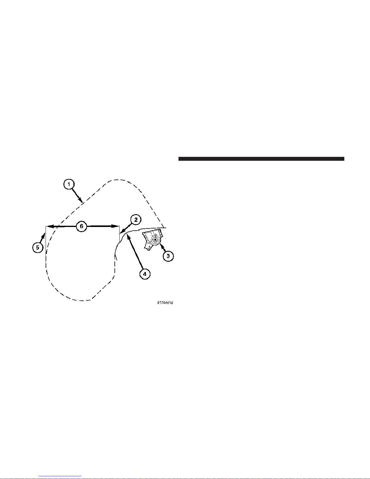
Figure 1
THINGS TO KNOW BEFORE STARTING YOUR VEHICLE 9
Figure 1 - Driver Air Bag Deployment Zone, depicts the
following.
1. Vertical Plane Passing Through Center of Steering
Wheel
2. 18.5 in (47 cm)
3. Vertical Plane Passing Through Maximum Rearward
Point that the Driver Air Bag Cushion Reaches
4. Steering Wheel
5. Driver Air Bag Retainer/Housing
6. Driver Air Bag Cushion
2

10 THINGS TO KNOW BEFORE STARTING YOUR VEHICLE
DRIVER AIR BAG/STEERING COLUMN SPECIFICATIONS
DRIVER AIR BAG CUSHION POSITION
DAB Diameter When Deployed (Full)
DAB Depth When Deployed (Full)
26.5 in (67 cm)
15 in (38 cm)
Maximum Rearward Displacement During De-
18.5 in (47 cm)
ployment (Fill)
STEERING COLUMN TILT POSITION RANGE
+/– 2.7 Degrees from Steering Column Tilt Pivot
Point
21.0 Degrees from Vertical is the Nominal Position

Figure 2
THINGS TO KNOW BEFORE STARTING YOUR VEHICLE 11
Figure 2 - Driver Air Bag Lateral Deployment Zone,
depicts the following.
1. Driver Seating Reference
2
2. Driver Air Bag Cushion Lateral Deployment Zone,
28 in (71 cm).
12 THINGS TO KNOW BEFORE STARTING YOUR VEHICLE
Figure 3
Figure 3 - Passenger Air Bag Deployment Zone, depicts
the following.
1. Passenger Air Bag Cushion
2. Vertical Plane from Point of Instrument Panel
3. Passenger Air Bag Module
4. Instrument Panel
5. Vertical Plane Passing Through the Maximum Rearward Point that the Passenger Air Bag Cushion Reaches
6. 18.5 in (47 cm)

Figure 4
THINGS TO KNOW BEFORE STARTING YOUR VEHICLE 13
Figure 4 - Passenger Air Bag Lateral Deployment Zone,
depicts the following.
1. 2.75 in (7 cm)
2
2. Passenger Air Bag Cushion Deployment Zone
3. 20 in (52 cm)
4. Reference Point
14 THINGS TO KNOW BEFORE STARTING YOUR VEHICLE
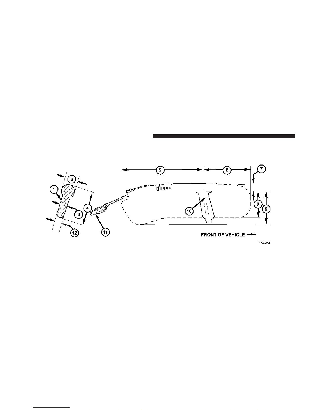
Figure 5

Figure 5 - Supplemental Side Air Bag Inflatable Curtain
Air Bag Deployment Zone, depicts the following.
1. Cross-Sectional Area Side View
2. 8.7 in (22 cm)
3. 3.5 in (9 cm)
4. 17.7 in (45 cm)
5. 40.7 in (103.5 cm)
6. 19.8 in (50.5 cm)
THINGS TO KNOW BEFORE STARTING YOUR VEHICLE 15
7. 3.5 in (9 cm)
8. 14.5 in (37 cm)
9. 16 in (40.5 cm)
10. B-Pillar Trim
11. Side-Curtain Air Bag Inflator Module
12. 3.5 in (9 cm)
2

16 THINGS TO KNOW BEFORE STARTING YOUR VEHICLE
Figure 6
 Loading...