

Page 1

Sprinter
OWNER’S MANUAL
2008
2008 Sprinter
Page 2

VEHICLES SOLD IN CANADA
With respect to any Vehicles Sold in Canada, the name
Chrysler LLC shall be deemed to be deleted and the
name Chrysler Canada Inc. used in substitution therefor.
DRIVING AND ALCOHOL
Drunken driving is one of the most frequent causes of
accidents.
Your driving ability can be seriously impaired with blood
alcohol levels far below the legal minimum. If you are
drinking, don’t drive. Ride with a designated non-drinking
driver, call a cab, a friend, or use public transportation.
WARNING!
Driving after drinking can lead to an accident. Your
perceptions are less sharp, your reflexes are slower,
and your judgment is impaired when you have been
drinking. Never drink and then drive.
This manual illustrates and describes the operation of
features and equipment that are either standard or optional on this vehicle. This manual may also include a
description of features and equipment that are no longer
available or were not ordered on this vehicle. Please
disregard any features and equipment described in this
manual that are not on this vehicle.
Chrysler LLC reserves the right to make changes in
design and specifications, and/or make additions to or
improvements to its products without imposing any
obligation upon itself to install them on products previously manufactured.
Copyright © 2007 Chrysler LLC
Page 3

Thank you for choosing the new
Sprinter Vehicle.
Before your first journey , please famili arize yourself with y our vehi cle an d how it
operates, as well as its driving, control
and convenience functions.
Before you drive off, read these Operating Instructions. This will help you get
the most out of your vehicle and avoid
endangering yourself and others.
Since the scope of delivery is base d on
the sales order, your vehicle’s equip-
Country-specific vehicle equipment, limited availability of items of special equipment or different product labeling i s
possible in some countries.
Chrysler Vans LLC reserves the right to
introduce changes in design, equipment
and technical features. You cannot,
therefore, base any claims on the data,
illustrations or descriptions contained in
these Operating Instructions.
Your nearest authorized Sprinter Dealer
will be happy to assist you further if you
have any other questions.
vehicle. For this r eason, you should always keep them in the vehicle and pass
them on to the new owner if you sell the
vehicle.
The technical documentation team at
ChryslerVans LLC wishes you safe and
pleasant driving.
nf_BA.book Page 1 Friday, January 25, 2008 3:53 PM
Page 4

Symbols Trademarks
ESP® is a registered trademark of
Chrysler Vans LLC.
* Optional equipment
G
Warning
H
Environmental no te
!
Caution
i
Tip
Action required
Sequence of actions (several )
Continuation symbol
nf_BA.book Page 2 Friday, January 25, 2008 3:53 PM
Page 5

Contents
Introduction
At a glance1
Safety2
Controls in detail3
Operation
4
Practical hints5
............................5
............................17
.....................................33
..................81
............................301
....................429
nf_BA.book Page 3 Friday, January 25, 2008 3:53 PM
Page 6

nf_BA.book Page 4 Friday, January 25, 2008 3:53 PM
Page 7

Introduction
Environmental protection
Introduction
Environmental protection
Environmental note H
Chrysler’s declared policy is one of comprehensive environmental protection.
The objectives ar e for the natur al resources which form the basis of our existence
on this planet to be used sparingly and in
a manner which takes the requirements
of both nature and humanity into ac-
Fuel consumption and engine, transmission, brake and tire wear depend on the
two following factors:
Operating conditions of your vehicle
Your personal dr iving style
You can influence both factors.
Observe the following notes:
Operating conditions
Do not carry any unn ecessary weight
in/on the vehicle.
Keep an eye o n th e ve hicle ’s f uel con-
sumption.
Remove roof racks once you no long-
er need them.
A regularly serviced vehicle will con-
tribute to environmental protection.
You should therefore adhere to the
specified service intervals.
nf_BA.book Page 5 Friday, January 25, 2008 3:53 PM
Page 8

Introduction
Environmental protection
In this manual, whenever you see instructions to discard materials, you
should first attempt to reclaim and recycle them. To preserv e our environment,
follow appropriate environmental rules
and regulations when disposing of materials.
Personal driving style
Do not depr ess the a cce lera tor pe dal
when starting the engine.
Do not warm up the engine when the
vehicle is stationary.
Adopt an anticipatory style of driving
and keep a sufficient distance from
other vehicles.
Avoid frequent, sudden acceleration.
Switch off the engine in stationary
traffic.
Environmental concerns and
recommendations
nf_BA.book Page 6 Friday, January 25, 2008 3:53 PM
Page 9

Introduction
Operating safety
Operating safety
Warning G
Engine exhaust, some of its constituents,
and certain vehicle components contain
or emit chemicals known to the State of
California to cause cancer and birth defects or other reproductive harm.
In addition, certain fluids contained in vehicles, and certain products of component wear, contain chemica ls known to
Warning G
Work carried out incorrectly on electronic
equipment and its software co uld cause
the equipment to stop working. The electronic systems are networked with each
other via interfaces. Tampering with the
electronic systems may also cause malfunctions in systems that have not been
modified. These malfunctions, however,
Warning (Continued) G
Other work carried out incorrectly or
modifications to th e vehicle could also
jeopardize operating safe ty.
Some safety systems only function while
the engine is running. Therefore, you
should not switch off the engine while
driving.
nf_BA.book Page 7 Friday, January 25, 2008 3:53 PM
Page 10

Introduction
Operating safety
Warning G
Always have maintenance work carried
out at an authorized Sprinter Dealer which
has the necessary specialist knowledge
and tools to carry out the work required.
The manufa c t urer recommends tha t yo u
use an authorized Sprinter Dealer for this
purpose.
In particular, work relevant to safety or on
safety-related systems must be carried
Warning G
A heavy impa ct to th e un der body , tir es or
wheels, for exa mp l e when bottoming out
on rough terrain or driving over an obstacle at high speed, could damage your vehicle. This also applies to vehicles
equipped with underbody protection.
In this case, have your vehi cle checked at
an authorized Sprinter Dealer which has
the necessary specialist knowledge and
Warning (Continued) G
In particular, work relevant to safety or on
safety-related systems must be carried
out at an authorized Sprinter Dealer.
nf_BA.book Page 8 Friday, January 25, 2008 3:53 PM
Page 11

Introduction
Operating safety
The manufacturer warrants to the original and each subsequent owner of a
Mercedes-Benz heavy-duty on highway
diesel engine th at:
(1) the engine was designed, built and
equipped so as to conform at the
time of sale with the applicable regulations adopted by the Federal Environmental Protection Agency, and
(2) the emission control system of such
years or 100000 miles (160000 km)
or 3000 hours of engine operation,
whichever occurs first.
The Owner’s Warranty Information Book
contains detailed information about the
warranties covering your Sprinter Vehicle.
The manufacturer may instruct its authorized Sprinter Dealer to carry out
technical inspections on ce rtain vehicles
thorized Sprinter Dealer, there is a
possibility that your vehicle has not been
registered in your na me with the manufacturer. The man ufacturer will only be
able to inform you about vehicle inspections if the manufacturer is in possession of your registration data.
It is advisable to have your vehicle registered at an authorized Sprinter Dealer.
Inform the manufacturer as soon as possible if your address has changed or
Service and warranty information
Registering your vehicle
nf_BA.book Page 9 Friday, January 25, 2008 3:53 PM
Page 12

Introduction
Operating safety
Do not allow the electronically stored total distan ce covered by your v ehicle to
be modified as a result of tampering with
the electron ics system.
This type of modification or failing to inform the buyer when selling th e vehicle
could constitute an offense punishable
by law, depending on the country concerned.
Having the engine power output of your
vehicle increa sed by ta mperin g with th e
electronic engine management system
will invalidate the vehicle’s general operating permit and insurance coverage, as
well as your warranty and warranty en titlement.
Modifications to the output of the engine
must be reported to the insurance pro-
Tampering with the electronic engine
management system modifies emission
values and it will not be possible to guarantee the operating safety of the engine
in every case. Increases in performance
may lead to malfunctions and con sequential damage to other assembli es.
If you sell the veh icle, failing to inform
the buyer of the modified engine power
output could constitute an offense punishable by law, depending on the country
concerned.
Digital speedometer and total
distance recorder
Modifying the engine power output
nf_BA.book Page 10 Friday, January 25, 2008 3:53 PM
Page 13

Introduction
Operating safety
The manufact urer recommends the use
of genuine Sprinter parts and conversion
parts as well as accessories that have
been expressly approved for your vehicle model (
page 600).
These parts have been subjected to special tests in order to determine th eir
safety, reliabil ity and suitability.
Body builder guideline
If you intend on making any alterations
to the vehicle, we strongly recommend
that you select one o f the following options in order to obtain all necessary information:
Contact the authorized Sprinter
Dealer nearest you to obtain a copy
of the Sprinter Body Builder Guideline.
Call Chrysler Vans LLC at telephone
(800) 992-1997 to request a copy of
Chrysler Vans LLC
P.O. Box 21-8004
Auburn Hills, MI 48321-8004
United States of America
Vehicle alterations
nf_BA.book Page 11 Friday, January 25, 2008 3:53 PM
Page 14

Introduction
Operating safety
Body builders and dealers who make any
modifications which may af fect the final
certification of the engine, vehicle or
equipment assume the sole responsibility for the vehicle, including labeling and
documentation, affected by their modifications.
It is their responsibility to certify that the
altered vehicle conforms to all applicable standards and regulations affected
by the vehicle alteration or continues to
comply with the motor vehicle safety
The manufacture r is not responsible for
any final certification or claims regarding product liability, or warranty claims,
which result from any component, assembly, or system being altered, or
which cause non-compliance with any of
the emission control standards or motor
vehicle safety standards, or which would
otherwise cause the vehicle to be or become defective or unsafe.
The manufacturer does not assume the
responsibility as the final stage manu-
Warning G
Any modifications or alterations of the
Sprinter vehicle not in compliance with
the Sprinter Body Builder Guideline and
the Sprinter Operator’s Manual may seriously inhibit its roadworthiness and safety and may lead to an accident resulting
in serious personal injury or death.
Consult the Sprinter Body Builder Guideline and the Sprinter Operator’s Manual
nf_BA.book Page 12 Friday, January 25, 2008 3:53 PM
Page 15

Introduction
Operating safety
Observe the following information when
using your vehicle:
The safety notes in this manual
Stickers and warning labels
If you should experi ence a p roblem w ith
your vehicle, particularly one that you
believe may affect its safe operation, we
urge you to immedi ately contact an authorized Sprinter Dealer to have the
problem diagnosed and corrected if required.
If the matter is not handled to your satisfaction, pl ease discuss the problem
with the Sprinter Dealer management,
Correct use
Warning G
Be sure to read the Operating Instructions.
Otherwise, yo u ma y no t b e awa re o f ce rta in
risks and could inju re y ourse lf or oth ers.
Warning G
Various wa rning la bels a re aff ixed to your
vehicle. These warning labels are intend ed to make you and others aware of various risks. You should not remove any of
these warning labels unless explicitly instructed to do so by information on the label itself. Removal of any of these labels
may cause you and ot hers to be u nawar e
Problems with your vehicle
nf_BA.book Page 13 Friday, January 25, 2008 3:53 PM
Page 16

Introduction
Operating safety
In the USA:
Chrysler Vans LLC Customer Center
P.O. Box 21-8004
Auburn Hills, MI 48321-8001
United States of America
Telephone: 800-992-1997
In Canada:
Chrysler Canada, Inc. Customer Center
P.O. Box 1621
Windsor, Ontario N9A 4H6
Telephone: (800) 465-2001
nf_BA.book Page 14 Friday, January 25, 2008 3:53 PM
Page 17

Introduction
REPORTING SAFETY DEFECTS
REPORTING SAFETY DEFECTS
In the 50 United States and Washington D.C.: If you believe that your vehicle has a defect, which could cause a crash or cause
injury or death, you should immediately inform the National Highway Traffic Safety Administration (NHTSA) in addition to notifying the manufacturer.
If the NHTSA receives similar complaints, it may open an investiga t ion, and if it finds that a safety defect exists in a group of
vehicles, it may order a recall and remedy campaign. However, NHTSA can not become inv olved in in divid ual p roble ms be tween
you, your dealer, and the manufacturer.
To contact NHTSA, you may either call the Auto Safety Hotline toll free at 1–888–327–4236 (T TY: 1-800-424-9153),
or go to http://www.safercar.gov; or write to: Administrator, NHTSA, 400 Seventh Street, SW., Washington DC 20590. You can
also obtain other information about motor vehicle safety from http://www.safercar.gov.
In Canada:
nf_BA.book Page 15 Friday, January 25, 2008 3:53 PM
Page 18

Introduction
Information regarding electronic recording devices
Information regarding electronic recording devices
(Including notice pursuant to California Code § 9951)
Please note that your vehicle is equipped with devices that can record vehicle systems data.
This informatio n helps, for example, to diagnose vehicle systems after a collision and to continuously improve vehicle safety.
Chrysler Vans LLC may acce ss the information and share it with others
for safety research or vehicle dia gnosis purposes
with the consent of the vehicle owner or lessee
in response to an official request by law enforcement or other government agency
for use in dispute r esolution involving Chrysle r Vans LL, its affiliates or sa les/service organization and/or
nf_BA.book Page 16 Friday, January 25, 2008 3:53 PM
Page 19

At a glance
1
At a glance
Cockpit............. 18
Instrument cluster............. 20
Steering wheel with buttons*............. 25
Center console............. 26
Overhead control panel*............. 27
Switch units............. 28
Door control panel............. 31
nf_BA.book Page 17 Friday, January 25, 2008 3:53 PM
Page 20

At a glance
Cockpit
1
Cockpit
N68.10-2287-31
nf_BA.book Page 18 Friday, January 25, 2008 3:53 PM
Page 21

At a glance
Cockpit
1
Function Page
1 Door control panel 31
2 Ligh t switch 130
3 Comb ination switch
Turn signals
High-beam head-
lamps
Windshield wipers
Rear window wiper*
135
131
210
212
4 Cruise control lever* 249
Function Page
7 Instrument cluster 20,
142
8 Storage compartment
9 Storage compartment
with interior lamp
137
Overhead control panel* 27
a Rear-view mirror * 208
b Rear view camera moni-
tor*
261
Function Page
e Jack and vehicle tool kit 515
f Glove box 288
g Center console 26
h Selector lever (automatic
transmission)
185
j Ignition lock 111
k Addition al switch unit 29
l Handbrake 191
nf_BA.book Page 19 Friday, January 25, 2008 3:53 PM
Page 22

At a glance
Instrument cluster
1
Instrument cluster
nf_BA.book Page 20 Friday, January 25, 2008 3:53 PM
Page 23

At a glance
Instrument cluster
1
Function Page
1 Instrument cluster on ve-
hicles without steering
wheel buttons
142
2 Instrument cluster on ve-
hicles with steering wheel
buttons*
142
3 On vehicles without
steering wheel buttons:
Changes the
4 On vehicles with
steering wheel buttons*:
Checks the engine
oil level
157
5 Reset button 142
6 Speedometer with: 145
Indicator and warning
lamps
22
Function Page
Function Page
8 Display on vehicles with-
out steering wheel buttons
148
9 Display on vehicles with
steering wheel buttons*
157
a Tachometer with: 145
Indicator and warning
lamps
22
b Instrument lighting
144
nf_BA.book Page 21 Friday, January 25, 2008 3:53 PM
Page 24

At a glance
Instrument cluster
1
Function Page
c Fuel gauge with:
Reserve fuel warning
lamp
Fuel filler flap location
indicator
Ö: Fuel filler flap is
on the lefthand side
145
475
i
Vehicles without steering wheel
buttons:
Display
8 contains a digital fuel
gauge.
Vehicles with steering wheel but-
tons*:
The tachometer contains an analog
fuel gauge.
Indicator and Warning Lamps
Page
v ESP
®
warning lamp 72
468
ASR warning lamp 73
74
465
/ Coolant level too low 474
D Coolant temperature
too high
475
1 Restraint sy stems
469
nf_BA.book Page 22 Friday, January 25, 2008 3:53 PM
Page 25

At a glance
Instrument cluster
1
Brake fluid level too
low
463
EBV malfunction 462
Malfunction in trailer's
brake booster
464
N Engine oil level warning as47
1
± Engine diagnostic
indicator lamp
477
Indicator and Warning Lamps
Page
Indicator and warning lamps Page
X Combination low tire
pressure/TPMS m alfunction telltale, USA
only
478
Low tire pressure telltale, Canada only
478
J Windshield washer/
headlamp cleaning system* washer fluid level
too low
482
Turn signal, rig ht 135
- ABS malfunction 466
k ASR malfunction 465
BAS malfunction 465
# ESP
®
malfunction 468
‰ Air cleaner dirty 477
A Reserve fuel 475
Fuel filler flap open 476
Indicator and warning lamps Page
nf_BA.book Page 23 Friday, January 25, 2008 3:53 PM
Page 26

At a glance
Instrument cluster
1
Indicator and warning lamps Page
Water in the fuel 482
# Battery charge mal-
function
469
. Defective bulb 483
Handbrake applied 191
B Low-beam headlamps
on
131
™ Operating spee d gov-
ernor on*
273
i
Vehicles with steering wheel buttons:
Corresponding messages may also
be shown in display
9
(
page 157).
nf_BA.book Page 24 Friday, January 25, 2008 3:53 PM
Page 27

At a glance
Steering wheel with buttons*
1
Steering wheel with buttons*
N46.10-2074-31
Function Page
1 Display 151
Controlling the operating system
2 To select a submenu or
adjust the volume
151
+
-
Up/increases the
volume
Down/decreases
t Ends a call/
rejects an incom-
ing call
4 To jump from one menu
to another
151
è
·
Forward
Backward
5 To jump from one
151
Function Page
nf_BA.book Page 25 Friday, January 25, 2008 3:53 PM
Page 28

At a glance
Center console
1
Center console
N68.10-2288-31
Function Page
1 Storage compartment 290
2 Radio* or COMAND*,
see the separate operating instructions
3 Air-conditioning control
panel
218
4 Center console switch
unit
28
Function Page
5 Storage compart-
ment or
CD changer*,
see the separate
operating instructions
6 Cup holder with
Ashtray
Cigarette lighter
291
294
nf_BA.book Page 26 Friday, January 25, 2008 3:53 PM
Page 29

At a glance
Overhead control panel*
1
Overhead control panel*
Function Page
1 Hands-free microphone
for telephone*
2 Switches the right-hand
reading lamp
on/off
137
3 Switches the automatic
interior lighting
on/off
137
Function Page
4 Eyeglass
compartment or
Anti-theft alarm sys-
tem (ATA)*
290
77
5 Switches the interior
lighting
on/off
137
6 Switches the left-hand
reading lamp
137
nf_BA.book Page 27 Friday, January 25, 2008 3:53 PM
Page 30

At a glance
Switch units
1
Switch units
Center console switch unit
N54.25-2915-31
Function Page
Opens/closes th e lefthand electric sliding
door*
92
&
Switches the left/right
seat heating*
on/off
122
Switches the rear win-
214
Activates/deactivates
ASR
74
Switches the hazard
warning flashers on/off
136
Central locking
Interior/rear
compartment
104
! Switches the Parktronic
system (PTS)*
on/off
253
nf_BA.book Page 28 Friday, January 25, 2008 3:53 PM
Page 31
At a glance
Switch units
1
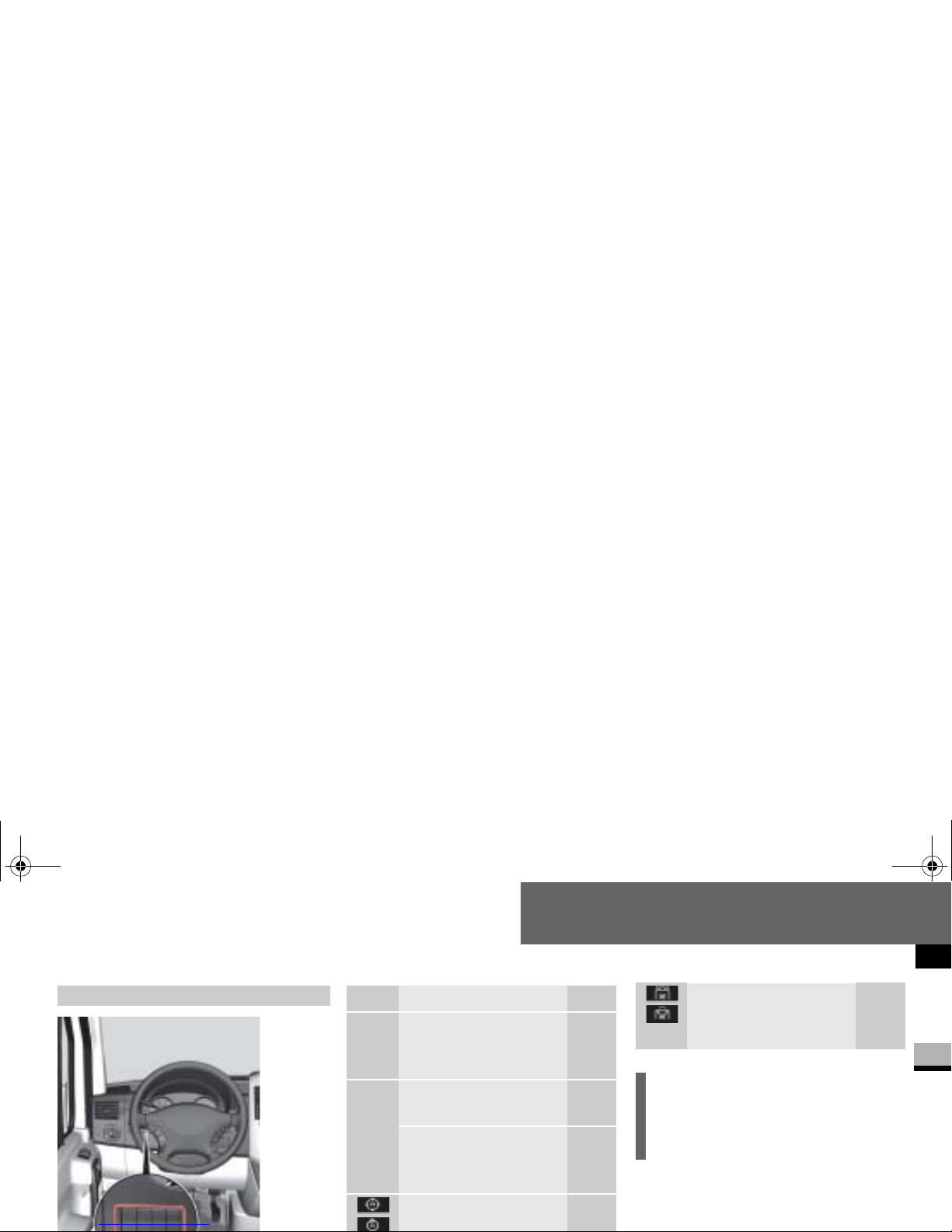
Additional switch units
N54.25-2913-31
Function Page
³ Switches the heater
booster function*
on/off
234
ö
³
Switches auxiliary
heating*on/off
238
Switches the heater
booster function*
on/off
234
Adjusts the working
275
Ventilates the load
compartment,
air in/air out*
247
i
The layout of the switches may vary,
depending on the vehicle’s equipment.
nf_BA.book Page 29 Friday, January 25, 2008 3:53 PM
Page 32
At a glance
Switch units
1
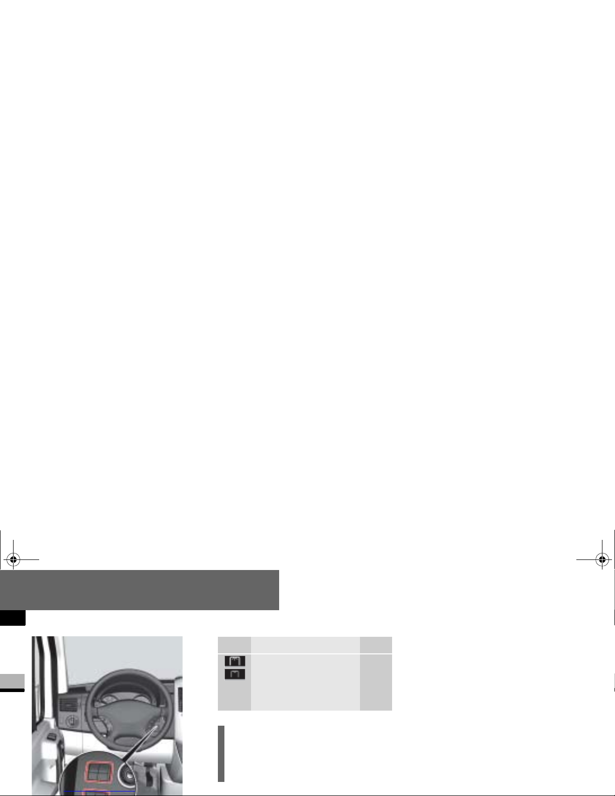
N54.25-2912-31
Function Page
Switches the rear-compartment convenience
interior lighting*
on/off
140
i
The lay out of the swit ches may vary,
depending on the vehicle’s equipment.
nf_BA.book Page 30 Friday, January 25, 2008 3:53 PM
Page 33
At a glance
Door control panel
1
Door control panel
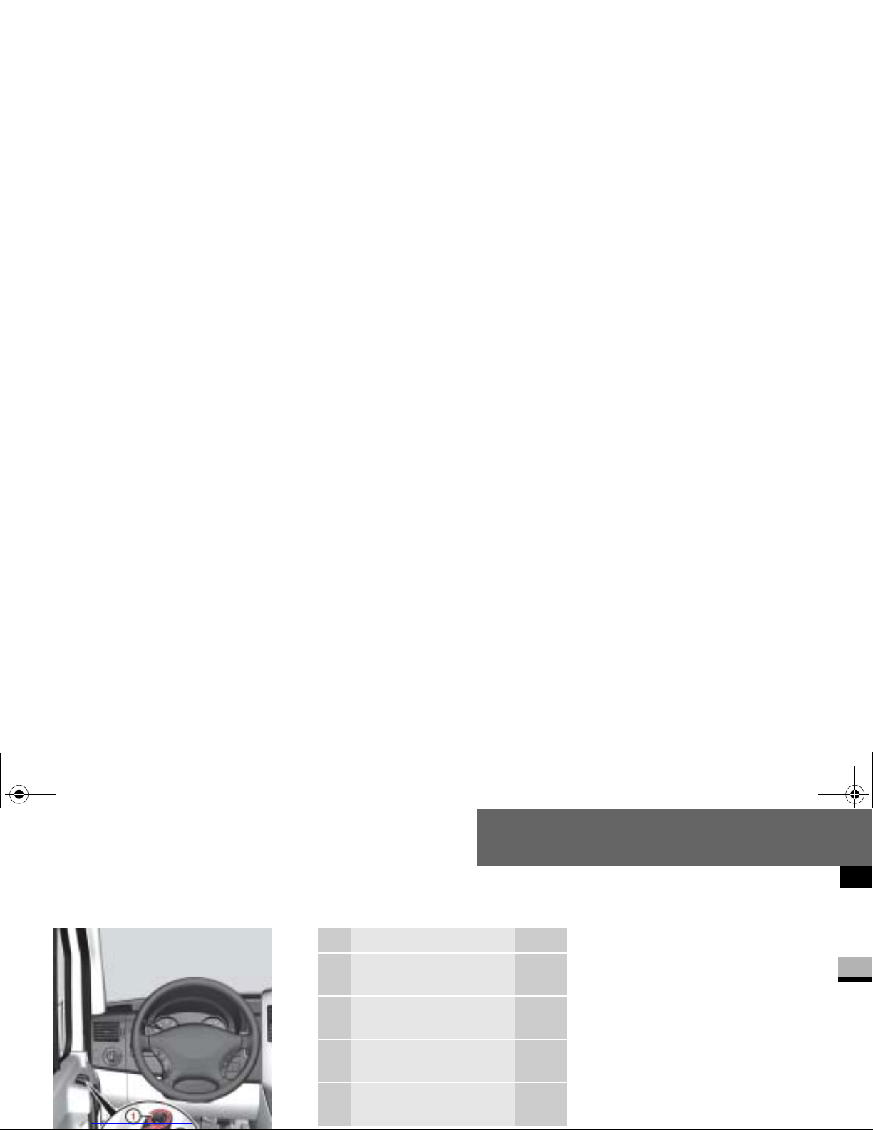
N54.25-2914-31
Function Page
1 Adjusts the exterior
mirrors*
208
2 Selects an exterior
mirror*
208
3 Opens/closes the left-
hand side window
244
4 Opens/closes the right-
hand side window
244
nf_BA.book Page 31 Friday, January 25, 2008 3:53 PM
Page 34

nf_BA.book Page 32 Friday, January 25, 2008 3:53 PM
Page 35
Safety
2
Safety
Occupant safety............. 34
Emergency exit............. 66
Driving safety systems............. 69
Anti-theft systems............. 77
nf_BA.book Page 33 Friday, January 25, 2008 3:53 PM
Page 36
Safety
Occupant safety
2
Occupant safety
This section contains all the most important information about the restraint systems in your vehicle. In an accident, your
vehicle collides with another object, e.g.
another vehicle. This may cause your vehicle to accelerate or decelerate extremely quickly. During this acceleration
or deceleration, the vehicle occupants
will be moved in the opposite dire cti o n
principally the seat belts supplemented
by emergency tensioning retractors, belt
force limiters and airba gs when necessary, is to minimize this risk of injury.
However, the seat belts and airbags cannot generally prevent injuries caused by
objects penetrating the vehicle from the
outside.
The most important restraint syste ms
are:
Additional protection is provided by:
SRS (Supplemental Restraint Sys-
tem), comprising:
emergency tensioning retractors
belt force limiters
airbags
iAn airbag increases the degree of
protection afforded to vehicle occupants
wearing a seat belt and is therefore only
Restraint systems
nf_BA.book Page 34 Friday, January 25, 2008 3:53 PM
Page 37
Safety
Occupant safety
2
This is partly bec ause an airbag is
not activated in all accident situations because in some cases it would
not provide any additional protection
to that alre ady a ffo rde d by a co rr ect ly fastened seat belt.
Furthermore, an activated airbag can
only provide increased protection if the
seat belt is being worn correctly, because:
the belt helps to hold the vehicle
occupant in th e b es t po s it i o n in rela-
e.g. in the event of a head-on collision, and is therefore better able to reduce the risk of injury
In accidents in which an airbag is
activated, the airbag will therefore
only offer an increase in the protection provided by the seat belt, i.e. additional protection, if the seat belt is
worn correctly.
Warning G
Modifications to or work incorrectly carried out on a restraint system (seat belt
and seat belt anchorages, emergency
tensionin g retractor, belt force li miter or
airbag) or i t s wiring, or tampering with
other networked electronic systems,
could cause the restraint systems to stop
working correc tly.
Continued
nf_BA.book Page 35 Friday, January 25, 2008 3:53 PM
Page 38

Safety
Occupant safety
2
The most important restraint systems in
the vehicle are the s eat belts and child
restraint systems. They are the most effective means of preventing vehicle occupants from moving towards the point
of impact and thus reducing the risk of
occupants hitting parts of the vehicle interior.
Warning (Continued) G
The airbags or emerge ncy te nsio ning retractors could, for example, be activated
inadvertently or could fail in accidents in
which the deceleration force is sufficient
to trigger the airbag. For this reason, do
not modify the restraint systems. Do not
tamper with electronic components or
their software.
Airbags
Warning G
Airbags do offer additional protection but
they are not a substitute for the seat
belts. To reduce the risk of serious or fatal
injuries, make sure t hat all occupants – in
particular, expectant mothers – wear
their seat belt cor rectl y at all tim es, hav e
adopted a normal sitting position and that
the seat is positioned as upri ght as poss i-
Seat belts
i
nf_BA.book Page 36 Friday, January 25, 2008 3:53 PM
Page 39
Safety
Occupant safety
2
Warning G
A seat belt th at is wor n incor rect ly or not at
all, or that is no t c orrec tly enga ged in t he
seat belt buckle, cann ot perform its intend ed
protective fun ction. In cer tain circu mst ances, you could be ser iously or even fat ally injured. Make sure, th at all oc cupant s – i n
particular, expectant mothers – wear their
seat belt corre ctly at a ll tim e s.
You must make sure that the belt:
Warning (Continued) G
fits closely
is not twisted
is routed across the middle of your shoul-
der
is not routed across your neck or under
your arm
is pulled tight across the lap by pulling up-
Warning (Continued) G
Avoid wearin g bulky clot hing, for ex ample
a winter co at.
Do not route the belt strap over sharp or
fragile objects, especially if these are located in or on your clothing, for example
eyeglasses, pens or keys. The belt strap
could otherwise tear in the event of an accident and you or other vehi cle occupants
could be injured as a result.
nf_BA.book Page 37 Friday, January 25, 2008 3:53 PM
Page 40
Safety
Occupant safety
2
Warning (Continued) G
A child must never be carried sitting on
the lap of a vehicle occupant. It would not
be possible to restrain the child, and the
child and other vehicle occupants could
be seriously or f a tal ly i nju r ed in t he ev e nt
of abrupt braking or an accident.
Persons less than 1.50 m tall or children
under 12 years of age cannot wear their
seat belt properly. They therefore require
Warning G
The seat belt only provides its intended
degree of protection if the seat backrest
is positioned as vertically as possible, allowing the occupant to sit upright. Avoid
seat positions th at d o n ot all o w the s e at
belt to be routed correctly. Therefore, position the bac krest as vertically as possible. Never drive with the backrest tilted
too far back. You could otherwise be seri-
Warning G
The seat belt cannot perform its protective function correctly if the seat belt
strap or buckle are dirty or damaged. You
should theref or e k ee p the bel t str ap and
buckle clean, as otherwise the belt latch
plate may not be able to engage correctly.
Check regul arly that the seat belts :
are not damaged
nf_BA.book Page 38 Friday, January 25, 2008 3:53 PM
Page 41
Safety
Occupant safety
2
Wearing seat belts
Warning (Continued) G
The belt strap could otherwise tear in the
event of an accident. You or others could
be seriously or fatally injured.
Always have seats belts that ar e damaged
or have been su bjecte d to a heavy l oad in
an accident replaced, and their anchor ages checked, at a qu alif ied sp ecia list work shop which has the necessary specialist
knowledge and tools to carry out the work
Warning (Continued) G
The manufacturer recommends that you
use an authorized Sprinter Dealer for this
purpose. In particular, work relevant to
safety or on safety-related system s must
be carried out at a qualified specialist
workshop .
For safety reas ons, th e ma nu fact ur er r ec ommends that you only use seat belts
that have been specially approved for
nf_BA.book Page 39 Friday, January 25, 2008 3:53 PM
Page 42
Safety
Occupant safety
2
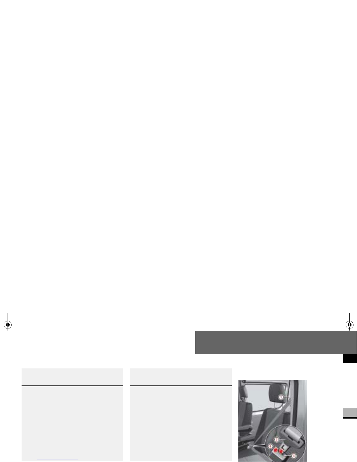
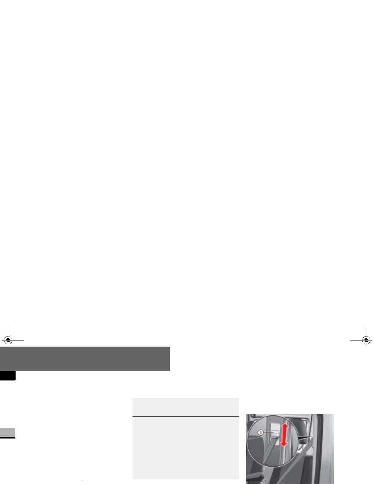
Pull the belt smoothly from the seat
belt reel holder.
Route the belt over your shoulder.
Click belt latch plate 2 into buckle
4.
Adjust the belt to the correct height
if necessary.
Pull the shoulder section of the belt
upwards to tighten the belt against
your body if necessary.
Adjusting the belt height
Adjust the belt height in such a way that
the shoulder belt is routed over the middle of the shoulder.
Warning G
Only adjust the belt height when the vehicle is stationary and the handbrake is applied.
You could otherwise lose control of the
vehicle as a result of the se at adjusting
movement and thereby endanger yourself
and others.
nf_BA.book Page 40 Friday, January 25, 2008 3:53 PM
Page 43
Safety
Occupant safety
2
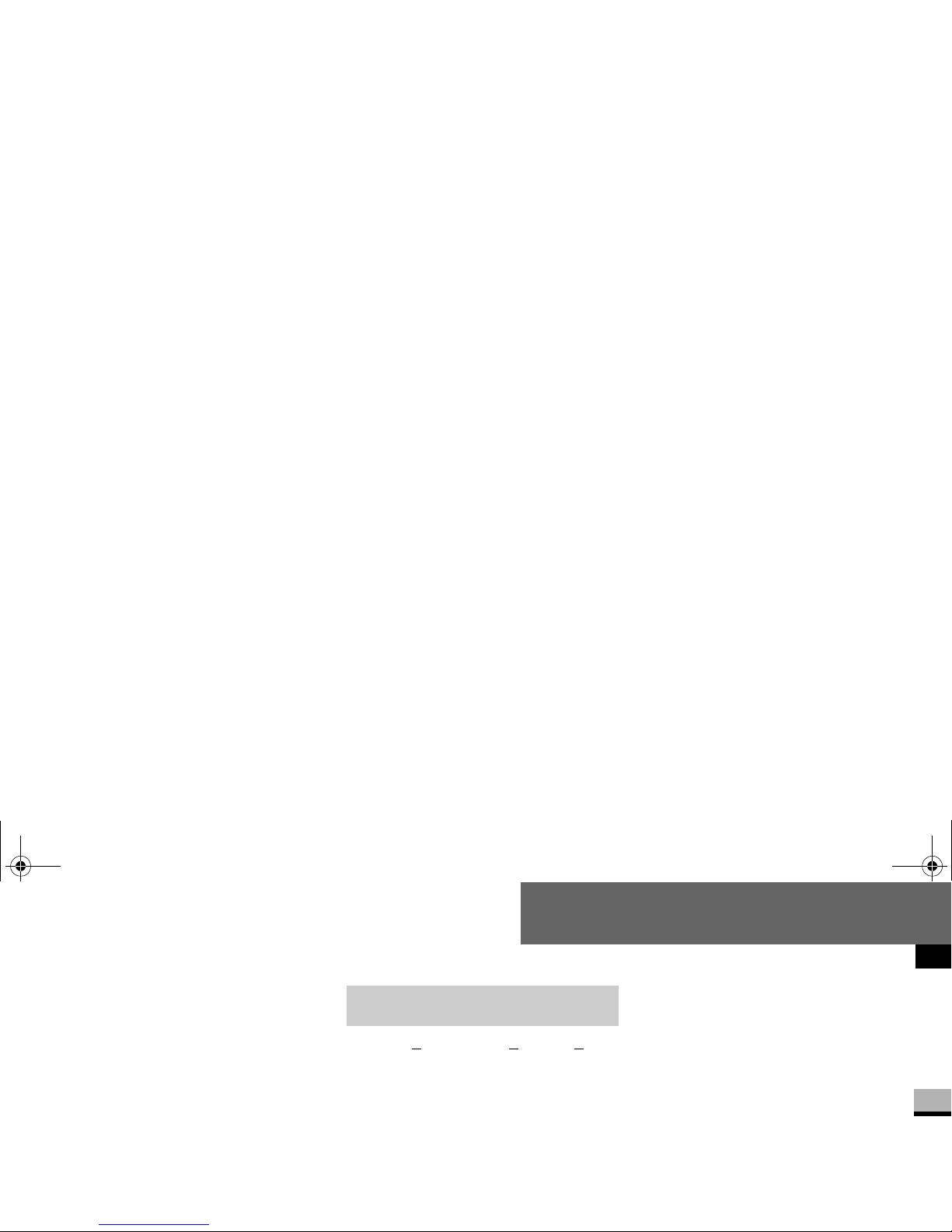
To raise the belt height: slide belt
sash guide
1 upward.
Belt sash guide
1 engages in vari-
ous positions.
To lower the belt height: press and
hold release button
5.
Slide belt sash guide1 to the de-
sired height.
Let go of release button 5 and
make sure that be lt sash guide
1
engages.
The SRS (S
upplemental Restraint System) may consist of the following components, depending on the equipment
level:
1 warning lamp
Emergency tensioning retractors
Belt force limiters
Airbag system with:
Airbag control unit
1 warning lamp
The SRS perfor ms a self-test at regular
intervals when the ignition is switched
on and while the engine is running. Malfunctions can therefore be detect ed in
good time.
The
1 warning lamp in th e instru-
ment cluster (
page 20) comes on for
approximatel y 4 seconds when you
switch on the ignition.
SRS (Supplemental Restraint
System)
nf_BA.book Page 41 Friday, January 25, 2008 3:53 PM
Page 44
Safety
Occupant safety
2
Activation of emergency tensioning
retractors, belt force limiters and airbags
In the event of a collision, the sensor in
the airbag control unit evaluates important physical data, such as duration, direction and rate of vehicle deceleration
or acceleration. Based on the evaluation
of this data and depending on the vehicle’s rate of longitudinal deceleration in
a collision, in the first stage, the airbag
control unit pre -e mptively triggers the
Warning G
A malfunction has occurred if the 1
warning lamp:
does not come on when you switch on the
ignition
does not g o out af ter appro ximatel y 4 se conds
lights up again
Warning (Continued) G
In this case, have the SRS system
checked and repaired immed i at el y at a
qualified specia lis t wo r kshop wh ich has
the necessary specialist knowledge and
tools to carry out the work required.
The manufacturer recommends that you
use an authorized Sprinter Dealer for this
purpose. In particular, work relevant to
safety or on safety-related systems m ust
nf_BA.book Page 42 Friday, January 25, 2008 3:53 PM
Page 45
Safety
Occupant safety
2
The front airbags are not triggered unless a second activation threshold is exceeded, i.e. if there is a greater rate of
vehicle deceleration in a longitudinal direction.
Criteria for triggering of emergency
tensioning retractors and airbags
To determine whether it is necessary to
trigger an emergency tensioning retractor or airbag, t he airbag contr ol unit eval uates the duration and direction of
The emergency tensioning retractor and
airbag activation thresholds are variable
and are adapted to the rate of the vehicle deceleration . This process is preemptive in nature as the airbag must be
deployed during – and not at the end of
– the collision.
i
Airbags are not triggered in all types of
accident. They are actually controlled
by complex sensor technology and evaluation logic. This process is pre-emptive
in nature as airbag deployment must
take place during the impact and must
be adapted to provide calculated, additional protection for the vehicle occupants. Not all airbags are triggered in an
accident.
The various airbag systems work independently of each other. However, all
nf_BA.book Page 43 Friday, January 25, 2008 3:53 PM
Page 46
Safety
Occupant safety
2
Vehicle deceleration or acceleration and
the direction of the force are essentially
determined by:
the distribution of the force during
the impact
the collision angle
the deformation characteristics of
the vehicle
the composition of the object in-
volved in the collision, for example
the other vehicle
Factors that cannot be seen or mea-
The vehicle may be substantially deformed
without an airbag bein g tri ggered , for ex ample if only relat iv ely ea sily- d eformable
vehicle parts such as the hood or fenders
are affected by the collision and the required deceleration threshold is not
reached. On the other hand, airbags may
be triggered even though the vehicle o nly
displays minor deformation, if, for example, rigid vehicle parts such as a longitudinal member are affected by the impact,
thus causing vehicle deceleration to exceed the pre-determined thre shold.
Emergency tensioning retractors,
belt force limiters
If the vehicle is equipped with a driver’s
airbag, the driver’s and the passenger’s
seat belts are equipped with emergency
tensioning retractors.
A belt force li mit er add iti onal ly ins tal led
in the seat belt reduces the load exerted
by the seat belt on the occupant when it
is triggered.
Emergency tensioning retractors ten-
nf_BA.book Page 44 Friday, January 25, 2008 3:53 PM
Page 47
Safety
Occupant safety
2
When the ignition is on, the emergency
tensioning retractor is activated:
only if the restraint systems are op-
erational (the
1-warning lamp
comes on for approximately 4 seconds after the ignition is switched
on.) (
page 41).
in the event of a head-on or rear-end
collision, if there is a high rate of vehicle acceleration or deceleration in
the initial stage s o f a collision
in the event of a side i mpact, if the
vehicle suddenly decelerates or ac-
If the emergency tensioning retractors
are triggered, you will hear a bang that is
generally harmless to your hearing. A
small amount of powder may also be released. The
1 warning lamp ligh ts
up.
i
Emergency tensioning retractors do
not correct:
incorrect sitting positions
incorrectly worn seat belts
Emergency tensioning retractors do
not pull occupants back towards the
backrest.
Warning G
If the emergen cy ten s io ning re tractors
have been triggered, have them replace d
at a qualified specialist workshop which
nf_BA.book Page 45 Friday, January 25, 2008 3:53 PM
Page 48
Safety
Occupant safety
2
Warning (Continued) G
The manufa c t urer recommends tha t yo u
use an authorized Sprinter Dealer for this
purpose. In particular, work relevant to
safety or on safety-related systems must
be carried out at a qualified specialist
workshop.
Observe the safety regulations when disposing of emergency tensioning retractors. You can see a copy of these
Airbag system
Warning G
To reduce the risk of serious or fatal
injuries in the event of an accident
with a high rate of deceleration, for
example due to an airbag inflating
within milliseconds, or due to sudden
braking, please observe the following
points:
Continued
Warning (Continued) G
All vehicl e occupants must select a seat
position in which they can wear their seat
belt correctly and which is as far back
from the airbag as possible. The seat position of the driver must be such that the
vehicle can be driven safely. The distance
from the driver’s seat to the pedals must
be such that the driver can fully depress
the pedals. The distance between the
driver’s ch est and the c enter of th e airbag
nf_BA.book Page 46 Friday, January 25, 2008 3:53 PM
Page 49
Safety
Occupant safety
2
Warning (Continued) G
Vehicle occupants should wear their
seat belt co rrectly at all times and
lean back against th e backrest, whi ch
should be positioned as upright as
possible. The head restraints should
support the bac k of the head at about
eye level.
Move the passenger’s seat as far to
the rear as possible, especially if a
child is secured in a restraint system
installed on this seat.
Warning (Continued) G
On vehicles with a passenger’s air-
bag, it is not permitted to secure a
rearward-facing child restraint system to the passenge r’s seat
( page 56). Children in a rearwardfacing child restraint system must be
secured on a suitable rear seat.
Do not lean forward, for example over
the padded boss of the steering
wheel, especi ally when the vehicle is
in motion.
Warning (Continued) G
Only hold the steering wheel by the
outer rim. This allows the airbag to inflate fully. If you hold the inside of the
steering wheel, you could be injured if
the airbag were to be triggered.
Do not put your feet on the da s h-
board.
Do not lean on the doors from inside
the vehicle.
Make sure that no persons, animals
nf_BA.book Page 47 Friday, January 25, 2008 3:53 PM
Page 50
Safety
Occupant safety
2
Your vehicle is equipped with the following airbags, dependin g on the equipment version:
Driver’s front airbag, located in the
steering wheel
Passenger’s front airbag , l o ca ted
above the glov e bo x
Thorax sidebags* in the outer sides
of the driver’s se at and the passenger’s individual se at
Windowbags* in the side of the roof
frame between the A and B-pillars
How airbags work
An airbag inflates w ith in milliseconds.
The
1 warning lamp in the instru-
ment cluste r comes on.
Warning (Continued) G
Do not cover the padded boss of the
steering wheel, the passenger’s airbag cover, the windowbag cover or
the thorax/sidebag cover with film or
other material. Do not affix any badges or stickers to these areas.
Do not hang any hard objects, for ex-
ample coat hangers, on the grab handles or coat hooks.
Do not place any it ems in the storage
compartment above th e passenger’s
i
If the airbags are triggered, you will
hear a bang an d a small amount of
dust may also be released. The bang
will not damage your hearing and the
dust does not constitute a health
hazard.
nf_BA.book Page 48 Friday, January 25, 2008 3:53 PM
Page 51
Safety
Occupant safety
2
When the vehicle occupant makes contact with the airbag, hot gas flows out of
the inflated airbag. This reduces the load
on the head and upper body of the vehicle occupant . The airbag i s therefor e in a
deflated st ate after an accident.
Warning G
After an airbag has been tr igg er ed :
airbag parts are hot – do not touch
them, otherwise you coul d be burnt
the airbags mus t be replaced at a
qualified sp ecialist worksho p which
has the necessary specialist knowledge and tools to carry out the work
required. The manufacturer recommends that you use an au thorized
Warning G
A small amoun t of fine pow der is releas ed as
an airbag inflates. This powder does not constitute a healt h hazard, nor do es it imply that
fire has broken out in the vehicle. This powder could cause short-term breat hing difficulties for persons suffering from asthma or
other respiratory conditions. To avoid these
breathing difficulties, you should either:
leave the vehicle immediately, if it is
nf_BA.book Page 49 Friday, January 25, 2008 3:53 PM
Page 52
Safety
Occupant safety
2
Front airbags
The front airbags are designed to increase protection to the driver’s and
passenger’s/passengers' head and
chest.
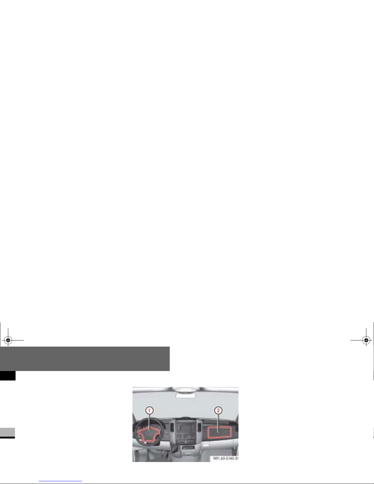
The driver’s airbag is located in the
steering wheel housing; the passenger’s
is above the glove bo x.
1 Driver’s airbag
2 Passenger’s airbag
The driver’s front airbag and passenger’s
front airbag are triggered:
in the initial stages of an accident
with a high rate of vehicle acceleration or deceleration in a longitudinal
direction
if the system determines that airbag
deployment can offer additional protection to that provided by the seat
belt
independently of other airbags in the
vehicle
N91.60-2140-31
nf_BA.book Page 50 Friday, January 25, 2008 3:53 PM
Page 53
Safety
Occupant safety
2
Thorax sidebags*
Warning G
For safety reasons, the manufacturer recommends that you use seat covers that
have been tested for Sprinter vehicles
and that have a seam for thorax/
sidebags. A thorax/ s ide bag may otherwise not inflate correctly and could fail to
provide the intended degree of protection
in the event of a col lis ion. You can o btai n
Warning G
To reduce the risk of injury to occupants
if a thorax/sidebag is triggered, make
sure that:
no persons, animals or obje cts are
present between the vehicle occupants and the thorax/sidebag deployment range
no accessories , for exam ple cup ho ld-
ers, are secured to the doors
Warning G
Observe the following to reduce the risk of
serious or fatal injury if the thorax/
sidebag is triggered:
Vehicle occupants – in partic ular, chil-
dren – must never lean their head
against the area of the window in
which the thorax/sidebag in flates.
Vehicle occupants mu st wear their
seat belt correctly at all times and
lean back again st the backr est, which
should be positioned as upright as
nf_BA.book Page 51 Friday, January 25, 2008 3:53 PM
Page 54
Safety
Occupant safety
2
The purpose of the thorax/sidebags is
to increase the level of protection for the
thorax (but not the head, neck and arms)
of the occupants on the side of the vehicle on which the impa ct occurs.
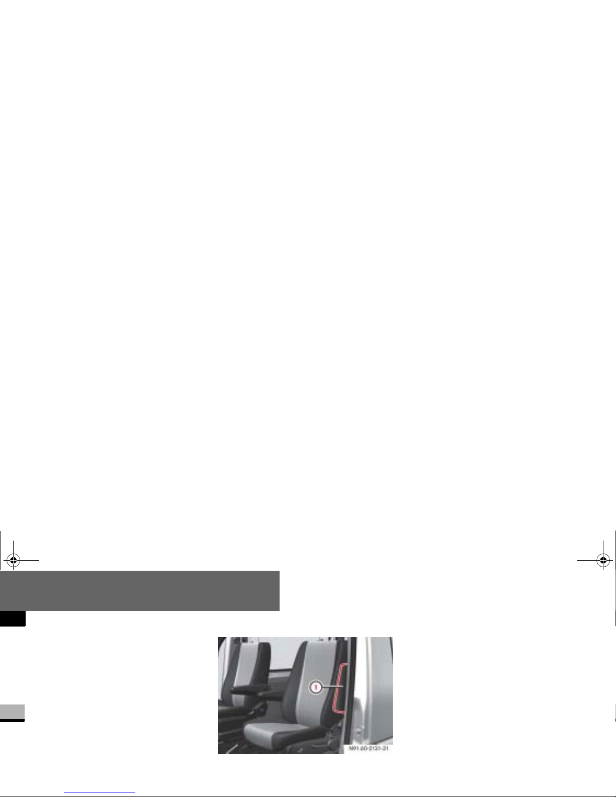
The thorax/sidebags are installed in the
outer sides of the backrest s on the driver’s seat and the passenger’s individual
seat
1 Thorax sidebag
The thorax sidebags are triggered:
on the side on which an impact oc-
curs
if the system determines that airbag
deployment can offer additional protection to that provided by the seat
belt
independently of the front airbags
In the event of an accident, the thorax
sidebag next to the outer seat side inflates between the door and the chest
area of the occupant.
nf_BA.book Page 52 Friday, January 25, 2008 3:53 PM
Page 55
Safety
Occupant safety
2
Windowbags*
i
You will find additional information
about airbag deployment on
(
page 48).
You will find additional information
about the triggering of emergency
tensioning retractors and belt force
limiters on (
page 44).
Warning G
To ensure that windowbags can provide
the intended degree of protection when
deployed, make sure that no persons, animals or obje cts are present betw ee n t he
vehicle occupants and the deployment
range of the windowbags.
Warning G
Observe the following to reduce the risk
of serious or fatal injury if th e windowbag
is triggered:
Vehicle occupants – in particular,
children – must never lean th eir hea d
against the area of the window in
which the windo wb ag inflates.
Vehicle occupants mu st wear their
seat belt correctly at all times.
nf_BA.book Page 53 Friday, January 25, 2008 3:53 PM
Page 56
Safety
Occupant safety
2
The windowbags are designed to increase protection to the head (but not to
the chest or arms) of the vehicle occupants on the side on which the impact
occurs.
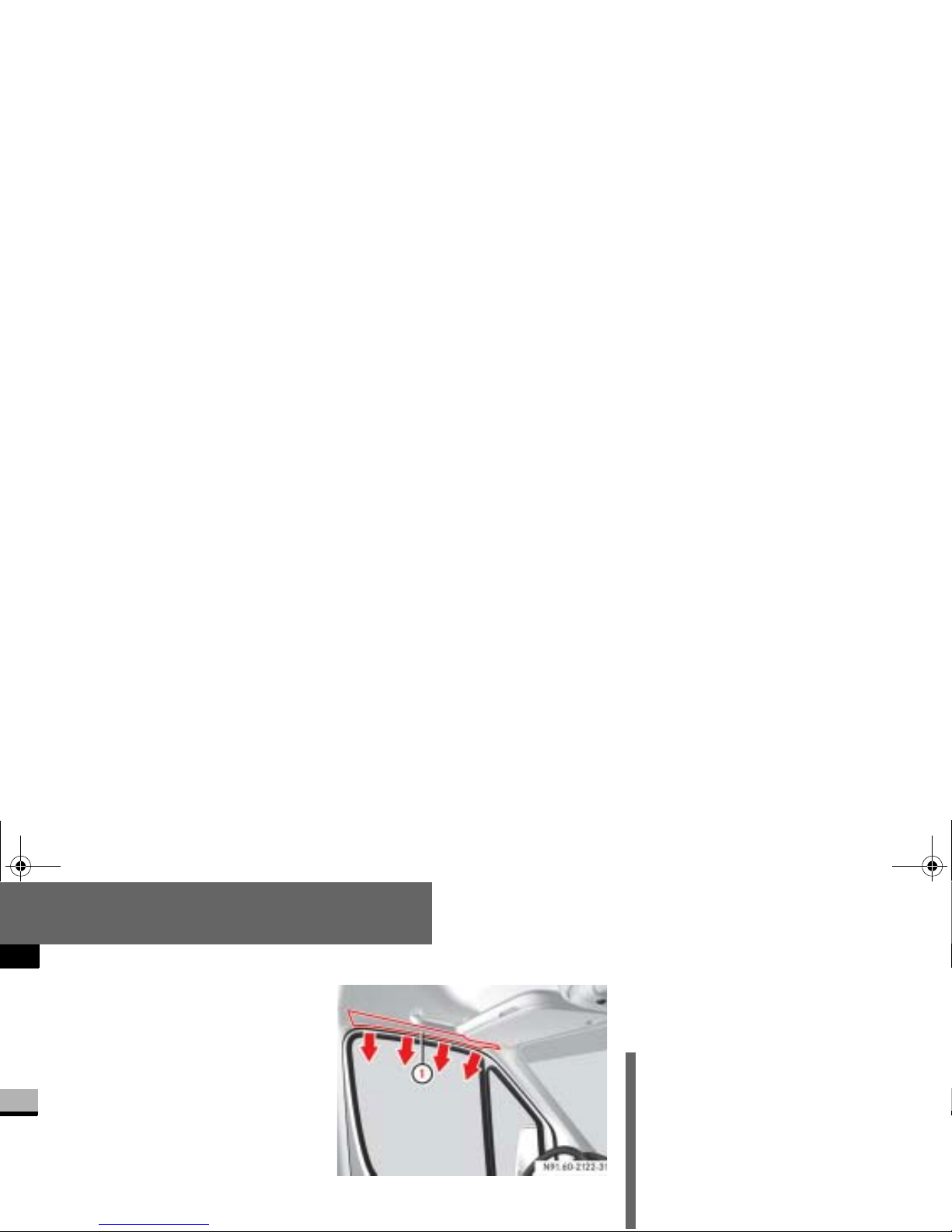
The relevant windo wbag is installed in
the side of the roof frame behind the
trim panel between t he A and B-pillar.
1 Windowbag
The windowbags are triggered:
on the side on which an impact oc-
curs
independently of the front airbags
i
You will find additional information
about airbag deployment on
(
page 48).
You will find additional information
about the triggering of emergency
tensioning retractors and belt force
limiters on (
page 44).
nf_BA.book Page 54 Friday, January 25, 2008 3:53 PM
Page 57
Safety
Occupant safety
2
If a child is trav eling in the vehicle:
secure the child in a child restraint
system appropriate to his/her age
and size, preferably on a suitable
seat in the rear
ensure that the child is strapped in
throughout the trip
You can obtain child seats and information about the correct child restraint system from any authorized Sprinter
Children in the vehicle
Warning G
Do not leave childr en unsup ervis ed in the
vehicle even if they are secured in a child
restraint system. The children could:
injure themselves on parts of the
vehicle
be seriously or even fa tall y i nju re d by
prolonged exp osure to extreme heat
or cold
Warning G
If the children open a door, they could:
cause injury to others as a result
get out of the vehicle and could either
injure themselves when doing so or
they could be injured by passing vehicles
sustain serious inj uries if t hey were t o
fall out of the v ehicle, due i n particular
nf_BA.book Page 55 Friday, January 25, 2008 3:53 PM
Page 58
Safety
Occupant safety
2
Child restraint systems
We recomme nd all infants and children
be properly restrained at all times while
the vehicle is in motion.
All lap-shoulder belts except the driver’s
seat belt have special seat belt retractors for secure fastening of child restraints.
To fasten a child restraint, follow child
restraint instructions for mounting. Then
pull the shoulder belt out completely
and let it retract. During seat belt retraction, a ratcheting sound can be heard to
indicate that the special seat belt retractor is activated. The belt is now locked.
Push down on child restraint to take up
any slack.
Warning (Continued) G
Do not carry heavy or hard objects inside
the vehicle or load compartment unless
they are secured. Y ou will find further information und er “Transporting”
( page 276) and “Features”
( page 287) in the “Controls in detail”
section.
An unsecured or in corre ctl y po sitio ned l oad
increases the risk of injury to occupants, par-
nf_BA.book Page 56 Friday, January 25, 2008 3:53 PM
Page 59
Safety
Occupant safety
2
To deactivate, re lease seat belt buckle
and let seat belt retract completely. The
seat belt can again be used in the usual
manner.
Warning G
Never release the seat belt buckle while
the vehicle is in mo tion, s ince th e specia l
seat belt retractor will be deactivated.
Warning G
To reduce the risk of serious or fatal injury
to a child in the event of an accident,
sharp braking or a sudden change in direction:
Always secure children less than 5 ft
(1.50 m) tall or under 12 years of age
in a special child restraint system installed on a suitable vehicle seat,
since the seat belts are n ot designed
for this body size.
Warning (Continued) G
It is not pe r mitt ed to sec ur e a ch il d in th e
passenger’s seat or the center position of
the front bench seat if the vehicle is
equipped with a passenger’s airbag.
Only secure a rearward-facing child restraint system on a suitable rear seat.
Continued
nf_BA.book Page 57 Friday, January 25, 2008 3:53 PM
Page 60
Safety
Occupant safety
2
Warning (Continued) G
A child must never be carried sitting on
the lap of a vehicle occupant. It would not
be possible to restrain the child as a result
of the forces acting in the event of an accident, braking or abrupt changes in direction. The ch ild would be thrown
against part s of the vehicle interior and be
seriously or fatally injured.
Vehicle occupants must wear their se at
Warning G
If the child restraint system is not installed correctly on a suitable vehicle
seat, the child may not be restrained in
the event of an accident or sudden braking and may be seriously or fatally injure d.
For this reason, al ways observ e the i nstallation instructions issued by the child restraint system manufacturer and the
intended use for the child restraint sy stem when fitting it.
Warning (Continued) G
Do not place o bj ect s (f or ex ample a cushion) underneath the child restraint system. The entire base of the child restraint
system must be in contact with the seat
cushion at all times.
Child restraint sy stem s mu st not be used
without the original cover. Replace damaged covers only with or ig ina l cov er s.
nf_BA.book Page 58 Friday, January 25, 2008 3:53 PM
Page 61
Safety
Occupant safety
2
Warning G
If you no longer require the child restraint
system, remove it from the vehicle or secure it with the seat belt.
The restraint system could otherwise be
thrown through the vehicle interior in the
event of an accident.
Warning G
A child secured in a chil d restraint system
could be seriously or fatally injured in th e
event of an accident, braking or a sudden
change in direction if the child restraint
system or its securing system is already
damaged or has been subjected to a load
in an accident.
Continued
Warning (Continued) G
Have restraint systems and thei r securing
systems which have been damaged or
subjected to a load in an accident
checked and, if necessary, replaced immediately at a qualified specialist workshop which has the necessary specialist
knowledge and too ls for the work required.
The manufacturer recommends that you
nf_BA.book Page 59 Friday, January 25, 2008 3:53 PM
Page 62
Safety
Occupant safety
2
The use of i nfa nt or ch il d r est rain ts is required by law in all 50 states, the District
of Columbia, the U.S. territories and all
Canadian provinces.
Infants and sm all children should be
seated in an appropriate infant or child
restraint system properly secured by a
lap/shoulder belt or, if so equipped, a
top tether anchorage point and a child
restraint lower anchorage system that
complies with U.S. Federal Motor Vehicle Safety Standards 213 and 225 and
A statement by the child restraint manufacturer of compliance with this standard can be found on the instruction
label on the restraint and in the instruction manual provided with the restraint.
When using any infant or child restraint
system, make sure to carefully read and
follow all manufacturer’s instructions for
installation and use.
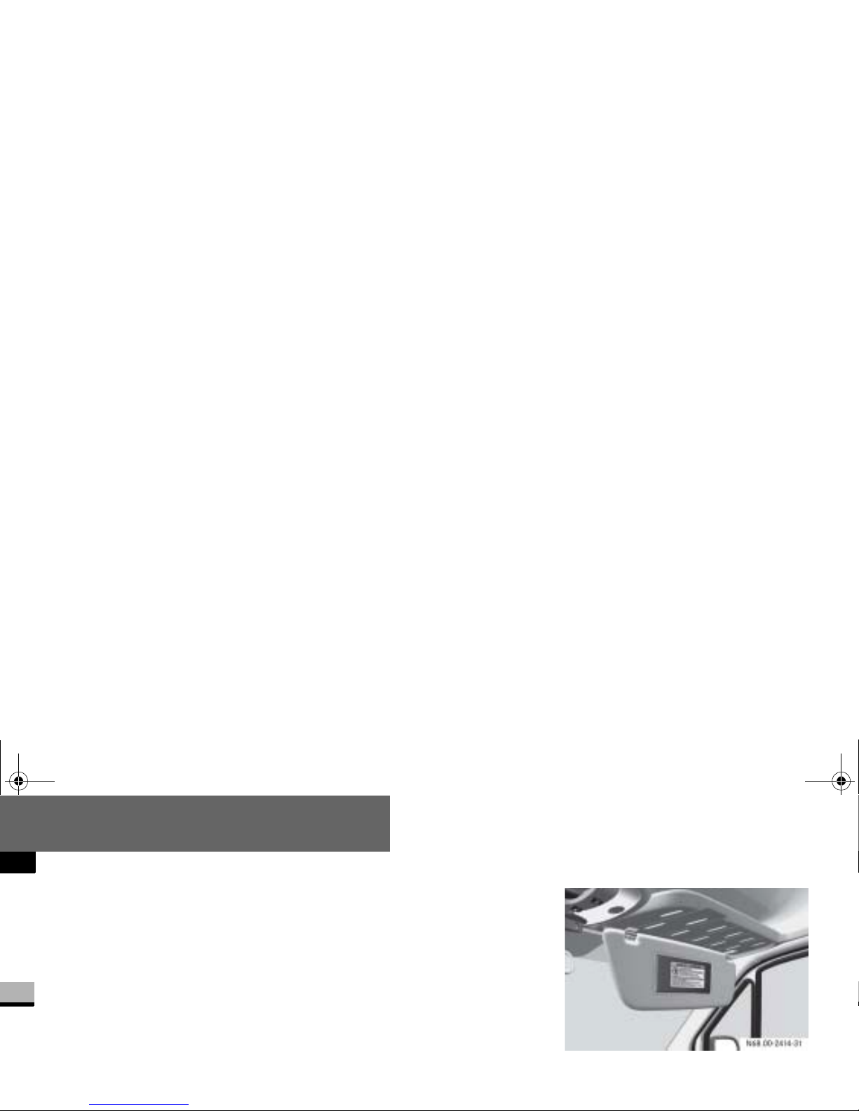
Please read and observe warning labels
affixed to inside of vehicle and to infant
Passenger sun visor with warning sticker
nf_BA.book Page 60 Friday, January 25, 2008 3:53 PM
Page 63
Safety
Occupant safety
2
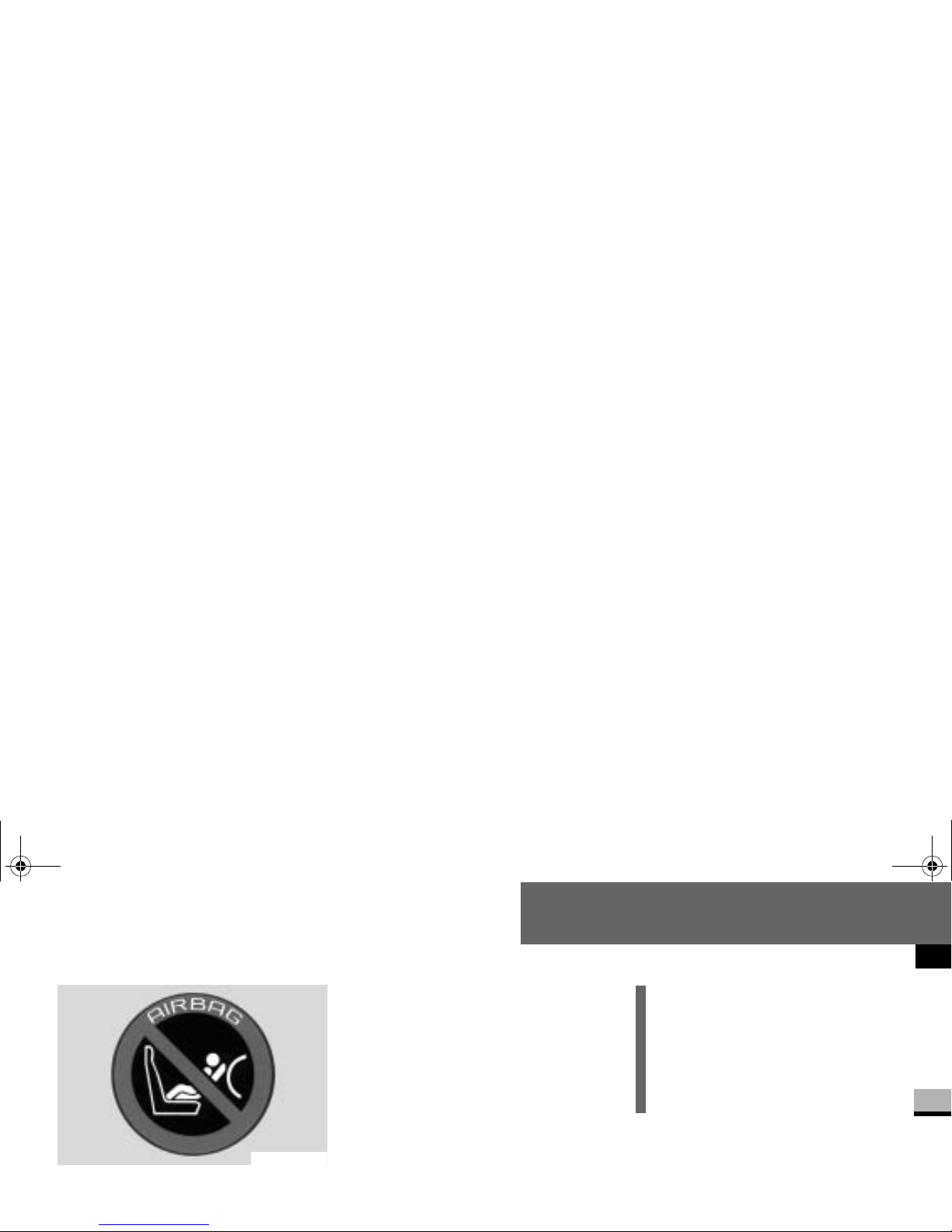
Warning symbol for rearward-facing child
seat
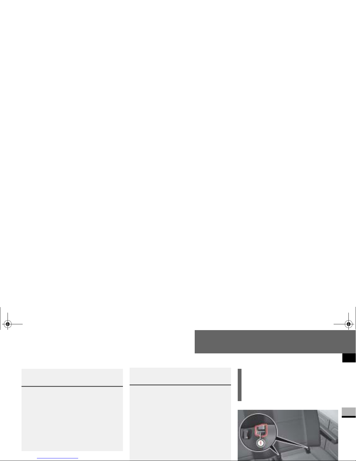
ISOFIX child seat securing system/
Child seat anchors - LATCH type
ISOFIX is a standardi zed securing system on the rear seats for special LATCH
(
Lower Anchors and Tethers for Chil-
dren) child restraint sy stems with
matching mounting fittings.
The LATCH type anchors f or child restraint systems are installed between
the seat cushion and the backrest:
on the outside left and right on nar-
N00.00-2620-31
i
Non-LATCH type child seats may also
be used and can ins t al le d using the
vehicle’s se at belt system. Install
child seat accord i n g to manu fa ct u rer’s instruction s.
nf_BA.book Page 61 Friday, January 25, 2008 3:53 PM
Page 64
Safety
Occupant safety
2
Warning G
A LATCH type child restra int syst em t hat
has been secured using the ISOFIX child
seat securing system is u nable to prov ide
adequate protection for children who
weigh more than 48 lbs (22 kg). For this
reason, only secure children weighing
less than 48 lbs (22 kg) in a LATCH type
child restraint syste m se cur e d using th e
ISOFIX child seat securing system. If the
Warning G
If the child restraint system has not been
installed correctly on a suitable vehicle
seat, the child cannot be res trained in the
event of an accident or sudden braking
and could be seriously or fatally injured.
You must therefore observe the installation instructions issued by the child restraint system manufacturer when
installing a child restraint system.
Warning (Continued) G
On the rear bench seat, only use LATCH
type child restra int systems with ISOFIX
child seat mountings that have been recommended by the manufacturer.
An incorrectly installed child restrai nt system could come loose and the child or
other vehicle occupants could be fatally
injured. You mu st therefore make sure
that the child restrai nt system is engaged
nf_BA.book Page 62 Friday, January 25, 2008 3:53 PM
Page 65
Safety
Occupant safety
2
Warning G
If the child restraint system or its secur ing
system, for example the ISOFIX child seat
securing system, are damaged or have
been subjected to a load in an accident,
the child secured in it could suffer severe
or fatal injuries in the event of an accident, heavy braking or a sudden change
of direction.
Continued
Warning (Continued) G
For this reason, have restraint systems
and their mountings checked immediately
and replaced if necessary at a qualified
specialist workshop which has the necessary specialist knowledge and tools to
carry out the work required if they are
damaged or have been subjected to a
load in an accident.
The manufacturer recommends that you
!CAUTION
Take care not to trap the seat belt on
the middle seat when you install the
child restraint system.
nf_BA.book Page 63 Friday, January 25, 2008 3:53 PM
Page 66
Safety
Occupant safety
2
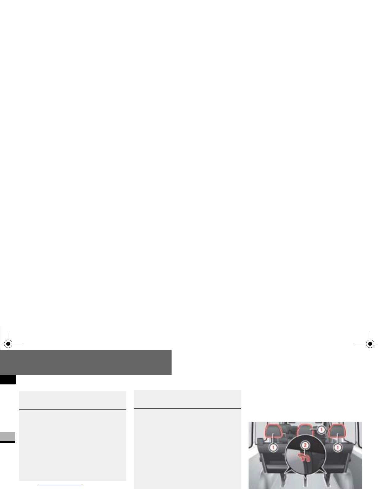
TopTether
The TopTether anc horages are on the
feet of the rear bench seat.
Warning G
Do not leave c hildre n unsupe rvised i n the
vehicle, even if they are secured by a child
restraint system. The children could:
injure themselves on parts of the ve-
hicle
be seriously or even f atally inju red by
prolonged exposure to extreme heat
or cold
Warning G
Do not expose child restraint systems to
direct sunlight. Me tall ic par ts of th e chil d
restraint system could heat up, for example, and the child could burn him/herself
on the hot parts.
If the children open a door, they could:
cause injury to others as a result
get out of the veh icle and could either injure themselves when doing so or they
could be injured by passing vehicles
nf_BA.book Page 64 Friday, January 25, 2008 3:53 PM
Page 67
Safety
Occupant safety
2
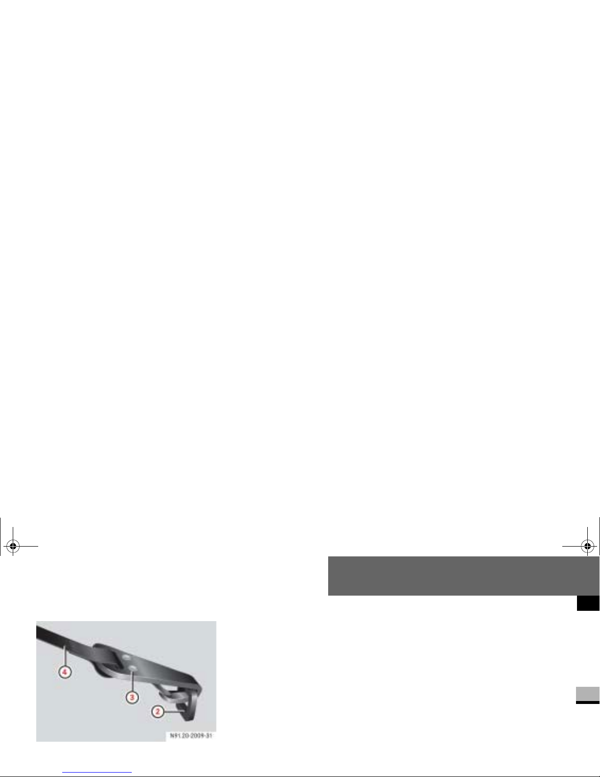
2 TopTether anchor ag e
3 TopTether hook
4 TopTether belt of LATCH type child re-
Slide head restraint 1 upward.
Guide TopTether belt 4 under head
restraint
1 from the front and be-
tween the two head restraint bars.
Hook TopTether hook 3 into
TopTether anchorage
2 on the feet
of the bench seat.
If necessary, slide head restraint1
back down a little (
page 121).
Make sure that TopTether belt
4
can move freely.
Install the LATCH typ e child restraint
system with TopTether. The manufacturer’s ins tallation instructions
must be observed.
nf_BA.book Page 65 Friday, January 25, 2008 3:53 PM
Page 68
Safety
Emergency exit
2
Emergency exit
The vehicle can be equipped with an
emergency exit window. The emergency
exit window is on ly intended for emergencies and may only be opened when
the vehicle is stationary.
In an emergency or following an accident, the occupants of the vehicle can
exit the vehic le vi a the op en eme rge ncy
exit window.
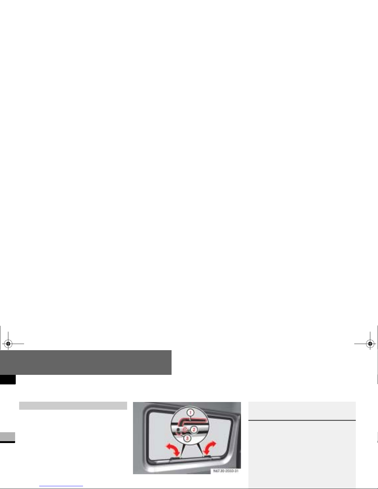
Emergency exit window*
1
Handles
Warning G
Compliance with the following requirements is essential in order to be able to
safely use the emer gency exit window in
the event of an emergency:
Inform the vehicle occupants about
the emergency exit window and explain its o perat ion bef ore sett ing out.
Clearly point out the known risks
nf_BA.book Page 66 Friday, January 25, 2008 3:53 PM
Page 69
Safety
Emergency exit
2
Warning (Continued) G
Only vehicle occupants who are able
to operate the emergency exit window are permitted to sit next to the
emergency exit window.
Access to th e emergency exit window
must be free of obstacles. Do not
place any large or heavy objects on
the seats or in front of the se ats next
to the emergency exit window.
Warning G
Please observe the following instructions
to reduce the risk of an accident or injury
when exiting the vehicle through the
emergency exit window:
Only open the emergency exit window
when the vehicle is stationary.
Take care not to tr ap anyone when
closing and opening the emergency
exit window. Somebody must hold the
Warning (Continued) G
Pay attention to the traffic conditions
when opening the emergency exit
window and make sure there is sufficient clearance.
Pay attention to the traffic conditions
when exiting the vehicl e and take account of the vehic le height and the
surrounding conditions.
Extreme cau tion must b e exerci sed in par-
nf_BA.book Page 67 Friday, January 25, 2008 3:53 PM
Page 70
Safety
Emergency exit
2
To open: turn both handles 1 to a
vertical position. This releases the
safety bolts
2.
The window is unlocked.
To close: close the windo w .
Turn both handles 1 to a horizontal
position. Make sure that the locking
mechanisms
3 are located on the
inside of the window frame.
The window is locked.
Renew the safety bolts 2 before dri-
ving the vehicle again.
Please contact your authorized
Sprinter Dealer for information about
how to do this.
Warning G
If you continue your journey without closing and locking the emergency exit window, it may come out of its frame and
cause an accident.
You should, therefore, check the locking
mechanism and safety bolts on the emergency exit win d ow before setting out.
The emergency exit window may only be
!CAUTION
Make sure there is enough space to
open the emergency exit window.
You must hold the open window in
position. Otherwise, you could damage it.
nf_BA.book Page 68 Friday, January 25, 2008 3:53 PM
Page 71
Safety
Driving safety systems
2
Driving safety systems
In this sectio n, you will find inform ation
about the following driving safety systems:
ABS (Antilock Brake System)
BAS (Brake Assist)
ESP
®
(Electronic Stability Program)
ASR (acceler ation skid control)
EBV (electronic brake force distribu-
tion)
i
The maximum effect of ABS, BAS,
ESP
®
, ASR and EBV can only be
achieved if you:
always drive with the correct tire
pressures ad justed according to
the load (
page 361)
use winter tires (M+S tires) in
wintry conditions, with snow
chains if necessary
Warning G
There is an in crea sed risk of a n ac cid ent if
you:
drive too fast , in pa rticu lar wh en c orne r-
ing and on a wet or slippery road surface
drive too close to the vehicle in front
The driving safety systems described in
this section cannot reduce this risk and
are unable to override the laws of physics.
nf_BA.book Page 69 Friday, January 25, 2008 3:53 PM
Page 72
Safety
Driving safety systems
2
ABS regulates the brake pre ssu re in
such a way that the wheels do not lock
when you brake. This allows you to continue steering wh en braking.
ABS works from a speed of about 3mph
(5 km/h) upwards, regardless of road
surface conditions.
ABS works on slippery surfaces, even
when you only brake gently.
There is a malfunction if the
- indica-
tor lamp is permanently lit while the engine is running (
page 466).
i
Only use wheels with the recommended tire sizes (
page 623), oth-
erwise the driving safety systems will
not work correctly.
Antilock Brake System (ABS)
Warning G
Do not depress the brake pedal several
times in quick succession (pumping). Depress the brake firmly and evenly. Pumping the brake pedal may reduce the
braking effect.
nf_BA.book Page 70 Friday, January 25, 2008 3:53 PM
Page 73
Safety
Driving safety systems
2
Braking
If ABS inter venes during b raking, you wi ll
feel the steering wheel vibrate gently
and the brake pedal pulsate.
If ABS intervenes:
Continue to depress the brake pedal
firmly until the braking situation is
over.
For full brake application:
Depress the brake pedal with maxi-
Brake Assist operates in emergency
braking situations. If you depress the
brake pedal qu ickly, BAS automati c a lly
increases the bra ke pressure, thereby
reducing the stopping distance.
Keep the brake pedal firmly de-
pressed until the emergency braking
situation is over.
ABS prevents the wh eels from locking.
Warning G
Always adapt your driving style to the prevailing road and weat he r conditions, and
maintain an adequately safe distance
from other road users as well as any obstacles on the road.
If ABS malfunctions, the wheels could
lock when you brake. This means that the
steerability of the vehicle is restricted
during braking and the stopping distance
Brake Assist (BAS)
nf_BA.book Page 71 Friday, January 25, 2008 3:53 PM
Page 74
Safety
Driving safety systems
2
Vehicles without steerin g w heel buttons:
There is a malfunction if the
k indi-
cator lamp is permanently lit while the
engine is running (
page 73).
ESP
®
monitors driving st ability and detects a tendency of the vehicle to understeer or oversteer (skidding) in good
time. ESP
®
stabilizes the vehicle by
braking individual wheels, limiting the
engine power output, and greatly assists
you when driving on wet or slippery road
surfaces. ESP
®
also stabilizes the vehi-
cle when braking.
®
Warning G
If BAS malfunctions, the brake system is
still available wit h th e f u ll b r ake boosting
effect. In an emergency braking situation,
however, the braking force will not be ad-
Electronic Stability Program
(ESP
®
)
Warning G
Proceed as follows if the v warning
lamp in the speedometer flashes:
Do not deactivate ASR under any cir-
cumstances.
Only depress the accelerator pe dal as
far as necessary when pulling away.
Adapt your driving style to suit the
prevailing road and weather conditions.
nf_BA.book Page 72 Friday, January 25, 2008 3:53 PM
Page 75
Safety
Driving safety systems
2
There is a malfunct ion if the # indica-
tor lamp is permanently lit while the engine is running (
page 468).
If ESP
®
malfunctions , eng ine powe r ou t-
put may be reduced.
ASR improves traction for a sustained
period, i.e. the transfer of power from
the tires to the road surface, and thus
also improves the driving stability of the
vehicle. ASR assist s you when pulling
away and acce lerating, especially on
smooth and slippery surfaces.
ASR brakes individual drive wheels and
limits the engine torque to prevent the
drive wheels from spinning. When ASR
!CAUTION
Only operate the vehicl e briefly (ma ximum of 10 seconds) on a brake dynamometer. The key must be turned
to position
1 in the ignition lock d ur-
ing this time. You could damage the
!CAUTION
Do not operate the vehicle o n a roller
dynamometer (for example for performance testing). If you wish to operate the vehi cle on a roller
dynamometer, please consult an authorized Sprinter Dealer beforehand.
You could otherwise damage the
drive train or the brake system.
Acceleration skid control (ASR)
nf_BA.book Page 73 Friday, January 25, 2008 3:53 PM
Page 76
Safety
Driving safety systems
2
If the road surface is not capable of providing sufficient traction, bearing in
mind the tires, load an d gradient, it is
not be possible to pull away smoothly
even with ASR.
Vehicles without steerin g w heel buttons:
There is a malfunction if the
k indi-
cator lamp is permanently lit while the
engine is running (
page 73).
If ASR malfunctions, engine power out-
Activating/deactivating ASR
ASR is automatically activated as soon
as the engine is switched on.
It may be best to deactivate ASR in the
following situati o ns:
if snow chains are being used
in deep snow
on sand or gravel
If you deactivate ASR:
the engine’s torque is then no longer
limited and the driv e wheels could
spin; the spinning wheels produce a
cutting effect for better traction
traction control still intervenes by
braking if one drive wheel reaches its
grip limit, for example if the surface
under one side of the vehicle is slippery. The wheel is th en braked to increase traction in this situation.
ESP
®
still intervenes to stabilize the
vehicle
nf_BA.book Page 74 Friday, January 25, 2008 3:53 PM
Page 77
Safety
Driving safety systems
2
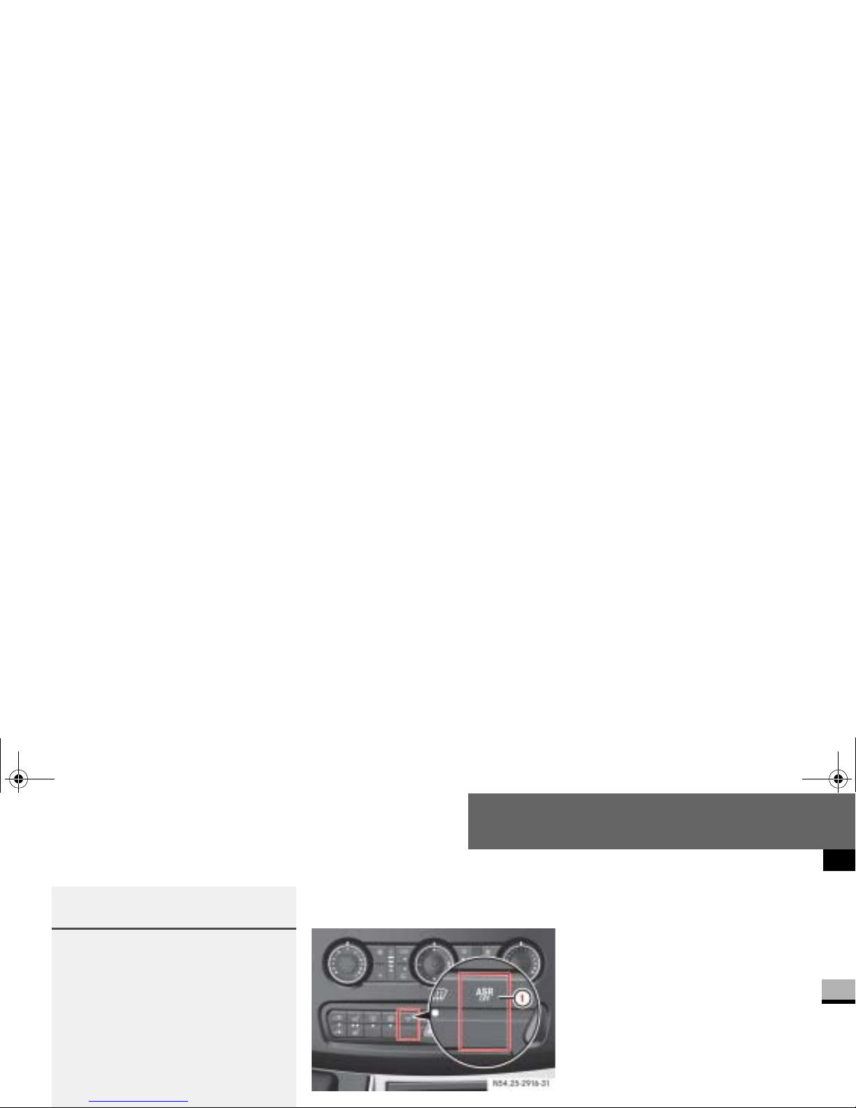
The ASR switch is located on the center
console.
1 To deactivate/activate ASR
To switch off: press upper
section
1 of the switch.
The
v warning lamp in the speed-
ometer lights up.
To switch on: press upper
section
1 of the switch again.
The
v warning lamp in the speed-
ometer goes out.
Warning G
ESP® remains active despite ASR having
been deactivated and carries out braking
interventions if this is necessary to improve driving stability. Thev warning
lamp flashes .
If ASR is deactivated, t here is an increased risk that the brake system of your
vehicle could overheat and be damaged
when subjected to high loads for a long
period of time. A hot brake system also in-
N54.25-2916-31
nf_BA.book Page 75 Friday, January 25, 2008 3:53 PM
Page 78
Safety
Driving safety systems
2
EBV monitors and regulates the brake
pressure at the rea r w heels to improve
driving stabil ity during braking.
There is a malfunction if the
#, k,
- and 6 indica tor lamps are per-
manently lit while the engine is running
(
page 462).
Electronic brake force distribution
(EBV)
Warning G
If EBV malfunctions , the brake system is
still available with the full brake boosting
effect. Howeve r, the rear wheels may
lock, for example if the brakes are applied
with maximum force. You could then lose
control of the vehicle and cause an accident. Always adapt your driving style to
the change in handling char acteristics.
Have the system ch ecked at an autho-
nf_BA.book Page 76 Friday, January 25, 2008 3:53 PM
Page 79
Safety
Anti-theft systems
2
Anti-theft systems
The immobilizer pre vents the vehicle
from being started without the correct
key.
To switch on: remove the key from
the ignition lock (
page 111).
To switch off: switch on the ignition
(
page 111).
A visual and aud ible alar m is tri ggered if
the alarm system is enabled and:
a door is opened
the hood is opened
Enabling the alarm system
Close all the doors.
Lock the vehicle using the ‹ but-
Deactivating the anti-theft alarm
system
Unlock the vehic le using the Œ
button on the key (
page 83).
The indicator lamp
in the central
locking switch (
page 104) goes
out.
Immobilizer Anti-theft alarm system (ATA)*
i
The vehicle l ocks again automatical -
nf_BA.book Page 77 Friday, January 25, 2008 3:53 PM
Page 80
Safety
Anti-theft systems
2
Switching off the alarm
Insert the key into the ignition lock.
or
Press the Πbutton ( page 83).
A visual and aud ible alar m is trig ger ed if
the inclination of the vehicle changes
while tow-away protection is enabled.
Tow-away protection is automatically
deactivated when you unlock the vehicle.
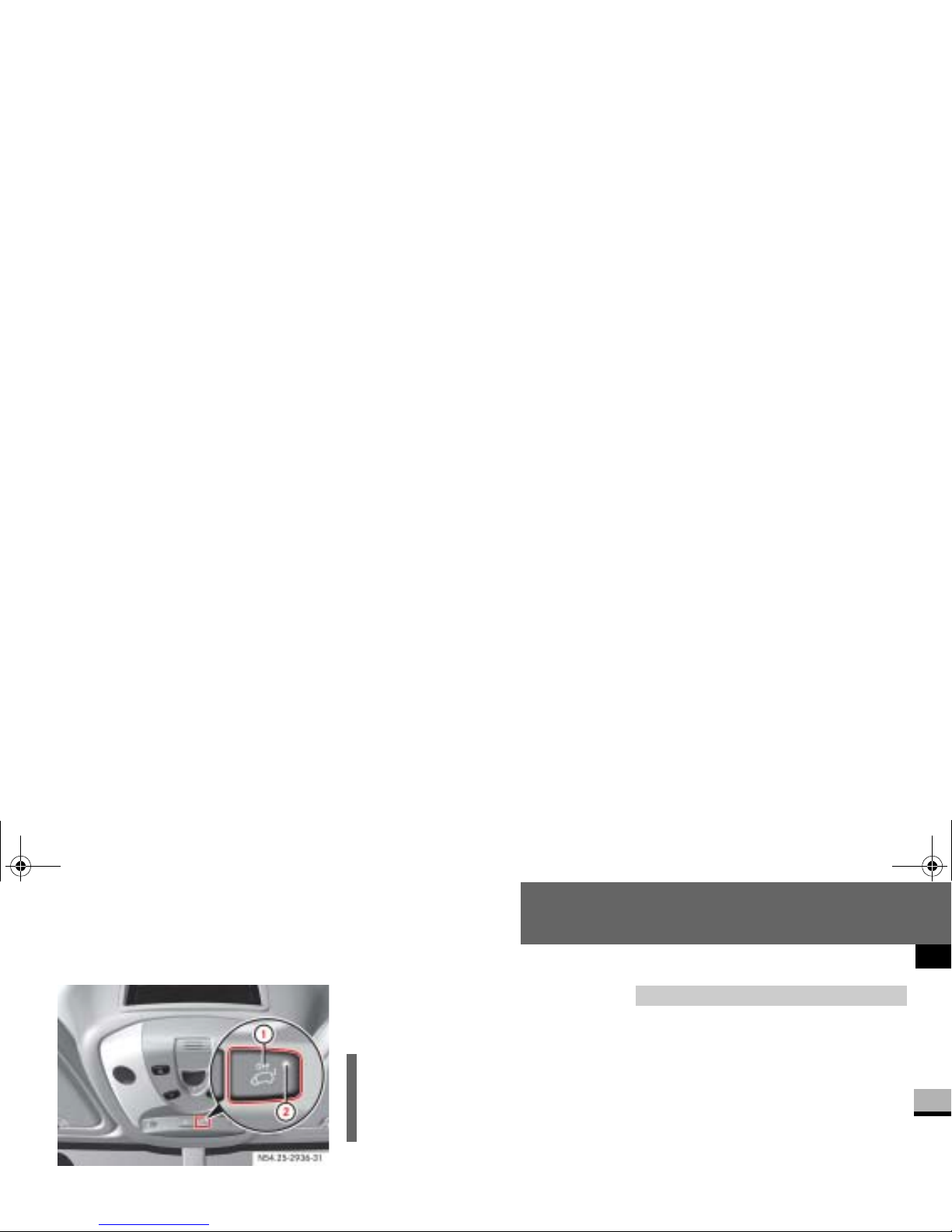
Deactivating the tow-away protection for transportation
Deactivate tow-away protection if the
vehicle is transported or loaded onto another vehicle. T his will prevent false
alarms.
The button is located in th e overhead
i
The alarm system will be triggered if
the vehicle has been locked with the
key and is then unlocked from the inside.
Tow-away protection*
i
The tow-away protection alarm is
triggered shortly before the wheel
leaves the ground if the vehicle is being jakked up on one side, for example.
nf_BA.book Page 78 Friday, January 25, 2008 3:53 PM
Page 81
Safety
Anti-theft systems
2
1 To deactivate tow-away protection
2 Indicator lamp
Turn the key to position 0 or 1
(
page 111) in the ignition lock or
remove the key.
Press button 1.
Indicator lamp
2 lights up for ap-
proximately 5 seconds after the but-
If the anti-theft alarm system is enabled
and the vehicle is locked, a visual and
audible alarm is triggered if one of the
side windows or the rear window on your
vehicle is smashed and someone reaches into the interior, for example.
Enabling the interior motion sensor
Close:
the side windows
i
When the ignition is switched off
(
page 111), you cannot deactivate
tow-away protection.
Interior motion sensor*
nf_BA.book Page 79 Friday, January 25, 2008 3:53 PM
Page 82
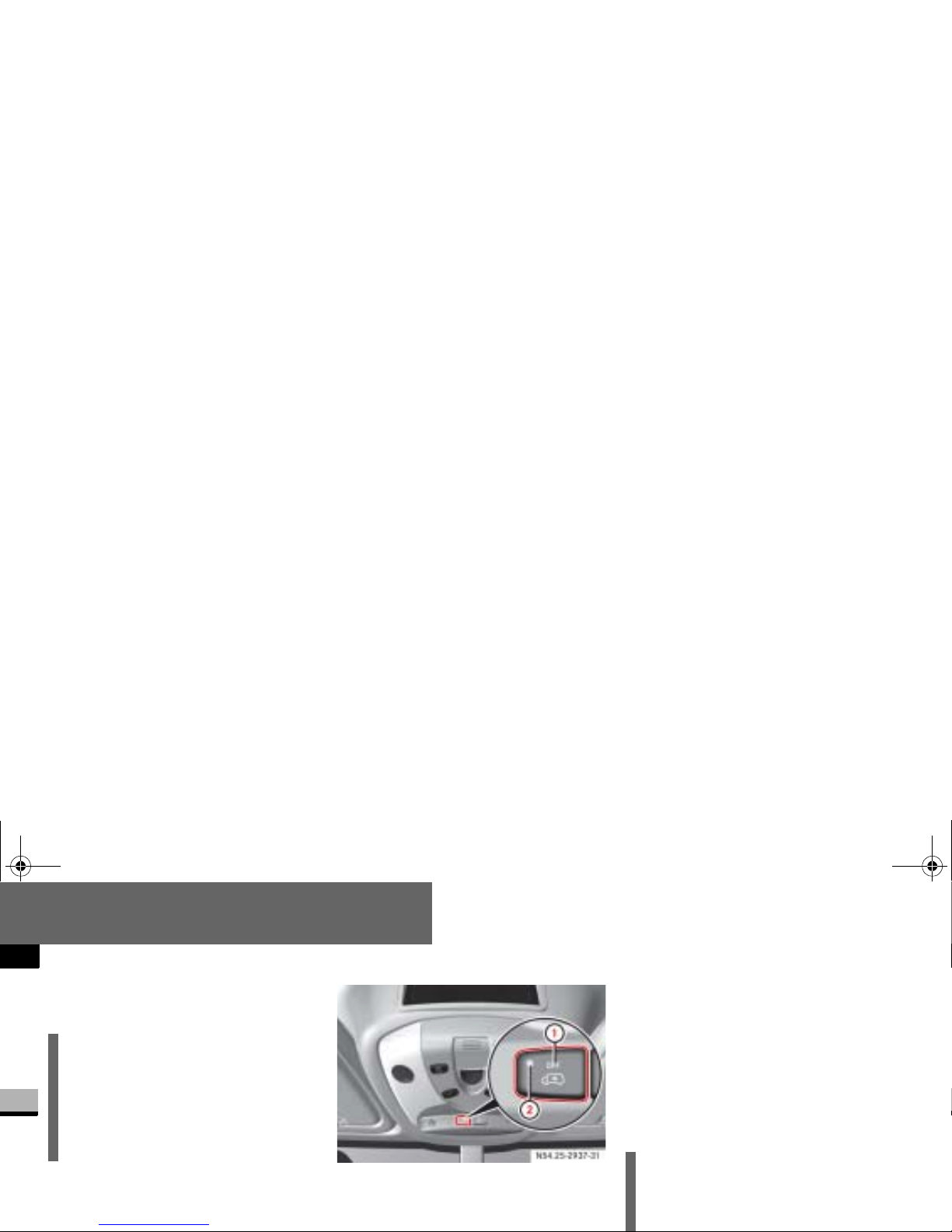
Safety
Anti-theft systems
2
The interior motion sensor is enabled
after approximately 40 seconds.
Deactivating the interior motion
sensor
1 To deactivate the interior motion sensor
2 Indicator lamp
Turn the key to position 0 or 1
(
page 111) i n the ignition lock or
remove the key.
Press button 1.
Indicator lamp
2 lights up for ap-
proximately 5 seconds after the button is released.
i
Do not leave anything (for example
mascots or coat hangers) hanging on
the rear-view mirror or on the grab
handles o n the roof trim. This will prevent false alarms.
i
The interior motion sensor remains
deactivated until you lock the vehicle
again.
nf_BA.book Page 80 Friday, January 25, 2008 3:53 PM
Page 83
Controls in detail
3
Controls in detail
Opening and closing............. 83
Key positions........... 111
Seats........... 112
Steering wheel adjustment........... 127
Lighting........... 129
Instrument cluster........... 142
Operating system without steering wheel buttons........... 147
Operating system with steering wheel buttons*........... 151
nf_BA.book Page 81 Friday, January 25, 2008 3:53 PM
Page 84
Controls in detail
3
Air conditioning........... 215
Auxiliary heating/ventilation*........... 236
Open air........... 244
Driving systems........... 248
Operating the vehicle........... 273
Transporting........... 276
Features........... 287
nf_BA.book Page 82 Friday, January 25, 2008 3:53 PM
Page 85
Controls in detail
Opening and closing
3
Opening and closing
Your vehicle is supplied with either 2 or
4* remote keyless entry transmitters or
4 keys* without remote control.
Vehicle keys* which were not included
with delivery must be activated before
they can be used. You c an obtain further
information at any authorized Sprinter
Dealer.
When leaving the vehicle, always take
the key* or remote keyless entry trans-
You will find information about opening
and closing your ve hicle with the key in
the “Locking and unlocking the vehicle
with the key” section (
page 88).
Included with your vehicle are 2 or 4* remote keyless entry transmitters with a
folding mechanical key.
Remote control with key
i
USA only:
This device complies with Part 15 of
the FCC rules. Operation is subject
to the following two conditions:
(1) This device may not cause harm-
ful interferenc e, and
(2) this device must accept any interference received, including interference that may cause undesired
nf_BA.book Page 83 Friday, January 25, 2008 3:53 PM
Page 86
Controls in detail
Opening and closing
3
Remote controls with keys which were
not included with delivery must be activated at an authorized Sprinter Dealer
before they can be used.
The remote keyless en try transmitter
transmits in all directions. It does not
transmitter by checking whether the
locking knobs on the driver's and passenger's doors move down and whether
the turn signals flash.
The remote control unlocks the driver's
door and/or all doors centrally. If programmed as a factory setting, it locks
the following cen tr ally:
the driver’s and passenger’s door
the sliding doors
the rear doors
The remote keyles s entry transmitter
will not function when there is a vehicle
key inserted in the ign ition lock.
i
Canada only:
This device complies with RSS-210
of Industry Canada.
i
If the driver’ s o r pa ss en g er’s door is
not completely closed, the respective
door is not locked.
If one sliding door or rear door is not
completely closed, all doors of the
load compartment are not locked.
nf_BA.book Page 84 Friday, January 25, 2008 3:53 PM
Page 87
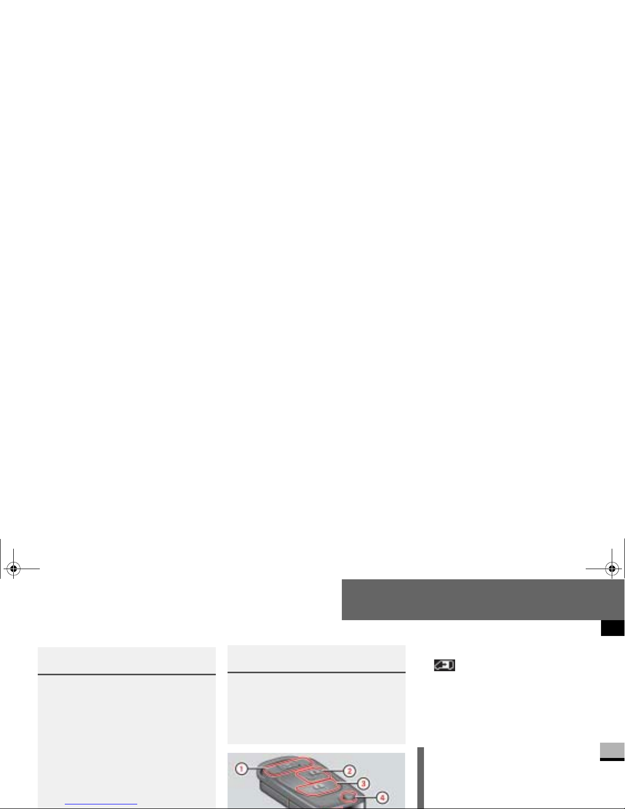
Controls in detail
Opening and closing
3
Remote control with key
1 To unlock the sliding doors and
rear doors and opens or closes the electric sliding door*
2 ΠUnlocking button
3 ‹ Locking button
4 Rel ea s e button for mechanical key
5 Ba ttery check lamp.
Warning G
Do not leave ch ildren u nsuperv ised i n the
vehicle, even if they are secured by a child
restraint system.
The children could:
injure themselves on parts of the vehicle
unlock the door on vehic le s wit h an elec-
tric sliding door by pressing the central
locking button, and then open the doors
and thereby injure othe r pe rs ons
Warning (Continued) G
get out of the vehicle and could either injure themselves when doing so or they
could be injured by passing vehicles
be severely or even fatally injured by prolonged exposure to intense heat
!
Do not expose the key to high levels
of electromagnetic r adiation, otherwise this may interfere with the func-
nf_BA.book Page 85 Friday, January 25, 2008 3:53 PM
Page 88
Controls in detail
Opening and closing
3
As a precaution, both remote controls
should always be carried.
Checking the batteries
The battery check lamp
5 comes on
briefly to indicate that the remote
control batteries are in order.
Change the batter ies immediately if
the lamp
does not light up briefly
during check (
page 540).
Locking and unlocking the vehicle
with the remote control
Unlocking the driver's door
Press the Πbutton.
The turn signals flash once.
The anti-thef t alarm system (ATA)* is
deactivated.
i
To prevent theft, only use the remote
control in the immediate vicinity of
the vehicle.
In an emergency, th e driver’s door
and rear door can also be unlocked
manually using the key.
i
If the batteries are checked within
signal range of the v ehicle, pressing
the
Œ or ‹ button will lock or
unlock the vehicle accordingly.
i
If you unlock the v ehicle using the
nf_BA.book Page 86 Friday, January 25, 2008 3:53 PM
Page 89
Controls in detail
Opening and closing
3
Unlocking the vehicle centrally
Unlock the driver's door.
Press the Πbutton within 2 sec-
onds agai n.
The turn signals flash once.
Locking the vehicle centrally
Press the ‹ button.
The turn signals flash three times if:
the drive authorization system or
the anti-theft alarm system
(ATA)* is activated
all the doors are c losed
Unlocking the sliding doors and the
rear door*
When the vehicle is lo cked, the
button can only be us ed to unlock the
sliding doors and the rear door.
Press the button.
The turn signals flash once.
Opening the electric sliding doors
Press and hold the button.
i
Make sure that the locking knobs
have dropped down.
nf_BA.book Page 87 Friday, January 25, 2008 3:53 PM
Page 90
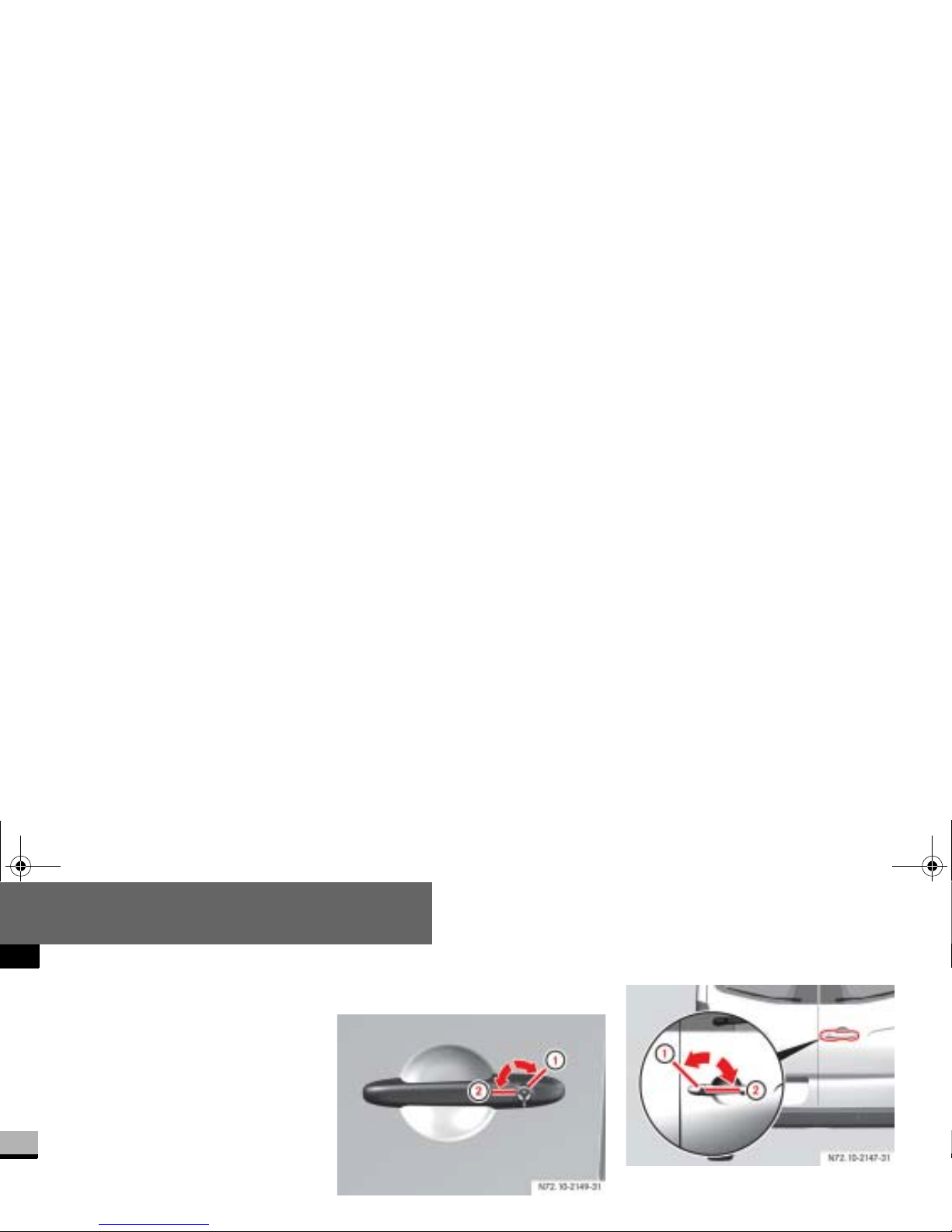
Controls in detail
Opening and closing
3
Locking and unlocking the vehicle
with the key
If the doors can no longer be locked or
unlocked with the remote control, you
can lock and unlock the driver's door
and the rear doors with the key.
Unlocking the vehicle
Driver's door
Rear door
1 To lock
2 To unlock
N72.10-2149-31
NCV2
N72.10-2147-31
nf_BA.book Page 88 Friday, January 25, 2008 3:53 PM
Page 91
Controls in detail
Opening and closing
3
The alarm ca n be disabled in the following ways:
Press the Πbutton on the remote
control.
or
Insert the key into the ignition lock.
Locking the vehicle
Only the driver's door and the rear doors
can be locked with the key.
For all other doors, press the locking
knob down.
Close the doors.
The doors are locked.
Insert the key all the way into the
rear door lock and turn it to the left.
The rear doors are locke d.
i
The anti-theft alarm system (ATA) is
triggered when you open the vehicle
using the key.
Opening the driver’s or passenger’s door from the inside
Warning G
Make sure nobody can become trapped
when you close or open the doors. Take
particular care, especi al ly when chil dre n
are near the vehicle.
Make sure there is su ff icient clearance
and that the tr affic area is clear w hen ope-
nf_BA.book Page 89 Friday, January 25, 2008 3:53 PM
Page 92
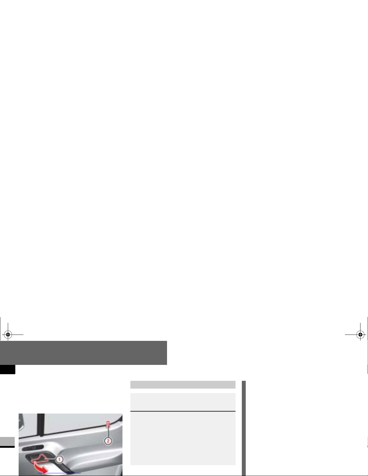
Controls in detail
Opening and closing
3
You can open the driver’s/passenger’s
door from the inside at any time, even if
it is locked. Open door only when conditions are safe to do so.
Sliding door
Warning G
If the vehicle is parked on an incline, the
sliding door may move of it s own accord if
it is open but not engaged. You or others
could be trapped.
Make sure that the sliding door is engaged
in the active reta ine r .
i
The sliding door is equipped with an
active retainer, which engages the
door at the end stop when opened.
Always make sure that the open sliding door is correctly engaged in the
detent.
To open the sliding door, it is necessary to pull the outside door handle
first, or press the button on the inside
handle, to release the sliding door
nf_BA.book Page 90 Friday, January 25, 2008 3:53 PM
Page 93
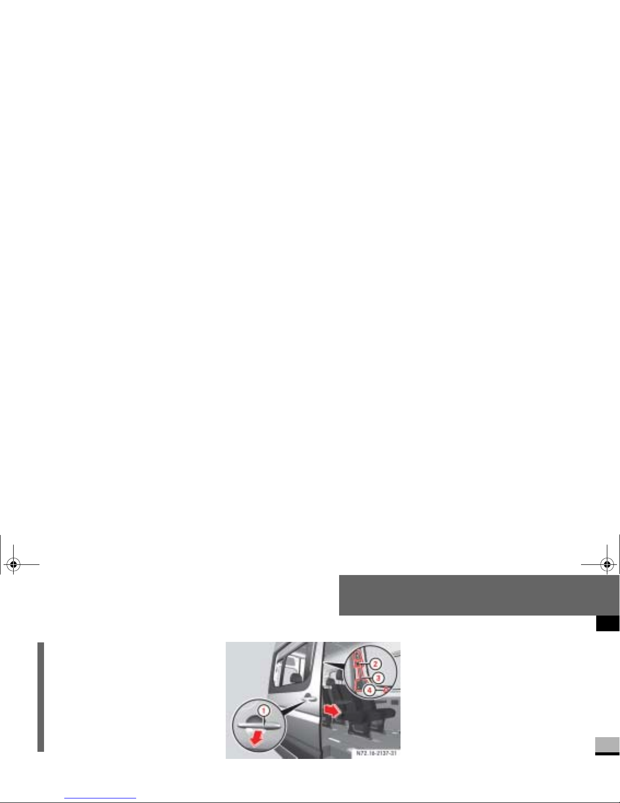
Controls in detail
Opening and closing
3
1 Outside door handle
2 Button
3 Inside door handle
Opening/closing the sliding door
from the outside
To open:
pull door hand le 1 to
open the sliding door.
Hold door handle 1 and slide the
sliding door towards the rear as far
as the stop.
To close: pull door hand le 1, to re-
lease the sliding door from its detent
and,
hold ing door handle1, pull the
door firmly towards the front until it
i
When you open/close the sliding
door, you can also detent it around
half way so that it is not always necessary to open the door to the end
stop to get in and out of the vehicle.
The intermediate detent does not fully engage the sliding door.
nf_BA.book Page 91 Friday, January 25, 2008 3:53 PM
Page 94
Controls in detail
Opening and closing
3
Opening/closing the sliding door
from the inside
Open sliding door only when conditions
are safe to do so.
To unlock: pull locking knob 4 up.
Only this sliding door unlocks. The
other doors remain locked.
To open: press button 2 to open
the unlocked slid ing door.
Hold door handle 3 and slide the
To close: press button 2 to release
the sliding door from its detent and,
holding door handle 3, pull the door
firmly towards the front until it engages.
To lock: press locking knob 4
down.
Only this sliding door is locked.
Electric closing aid*
Your vehicle may be equippe d with an
Depending on the vehicle’s equipment,
there are electric sliding doors on the
left and/or right-hand side.
Open sliding doo r only when conditions
are safe to do so. You can operate the
electric sliding do or as follows:
Switch on the center console
Switch in the doorway (B-pillar)
Inside door handle
Outside door handle
Electric sliding door*
nf_BA.book Page 92 Friday, January 25, 2008 3:53 PM
Page 95
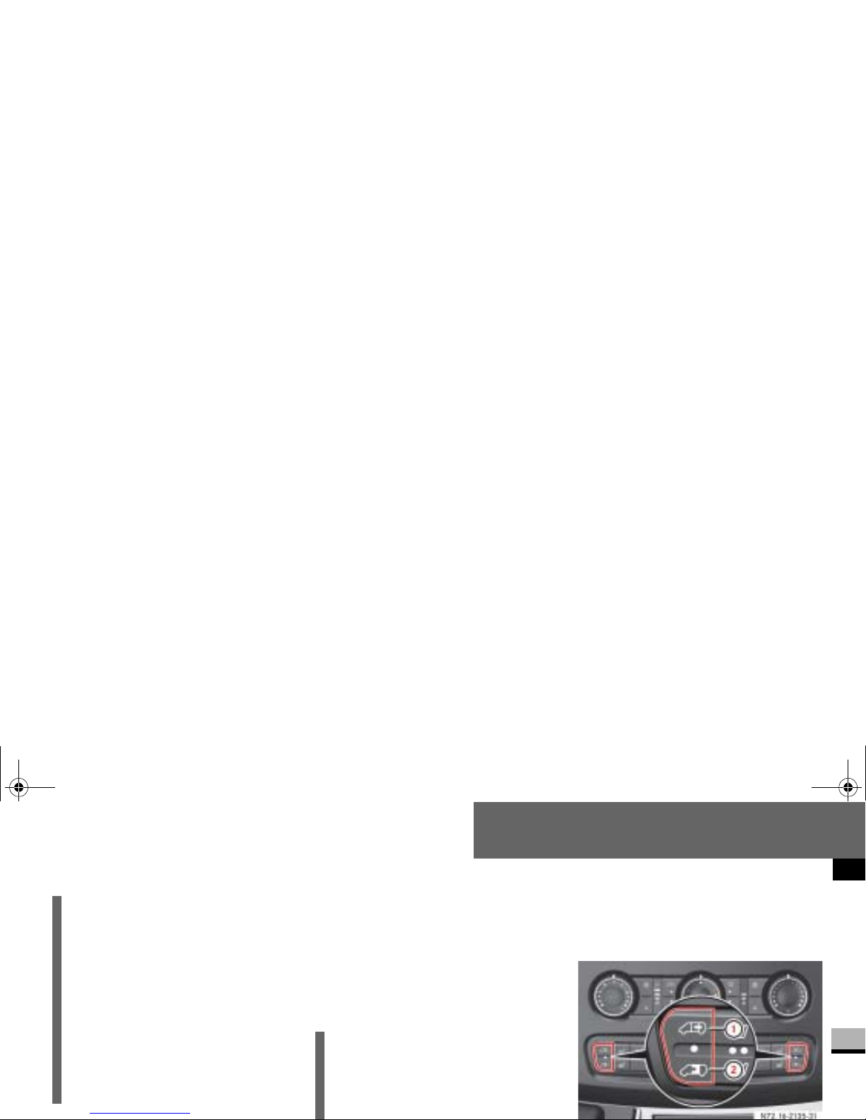
Controls in detail
Opening and closing
3
If the electric drive of the sliding door is
at risk of overheating, e.g. as a result of
frequent opening and closing within a
short amount of time, the sliding door
opens complete ly and is locked (function override). After approx. 30 seconds,
the sliding door is again operational.
Opening/closing using the switch
Observe the notes on anti-trap protection (
page 98).
i
Following a batt ery di sco nnec tio n or
malfunction, it is necessary to fully
close the sliding door once by pressing and holding the sw itch on the
center console or in the doorway
(
page 93) and then to fully open
and close the door once by pressing
one of the swit ches briefly. This restores normal operation of the sliding door.
i
In the event of a malfunction or if the
battery is disconnected, you can disconnect the sliding door from the
N72.16-2135-31
nf_BA.book Page 93 Friday, January 25, 2008 3:53 PM
Page 96
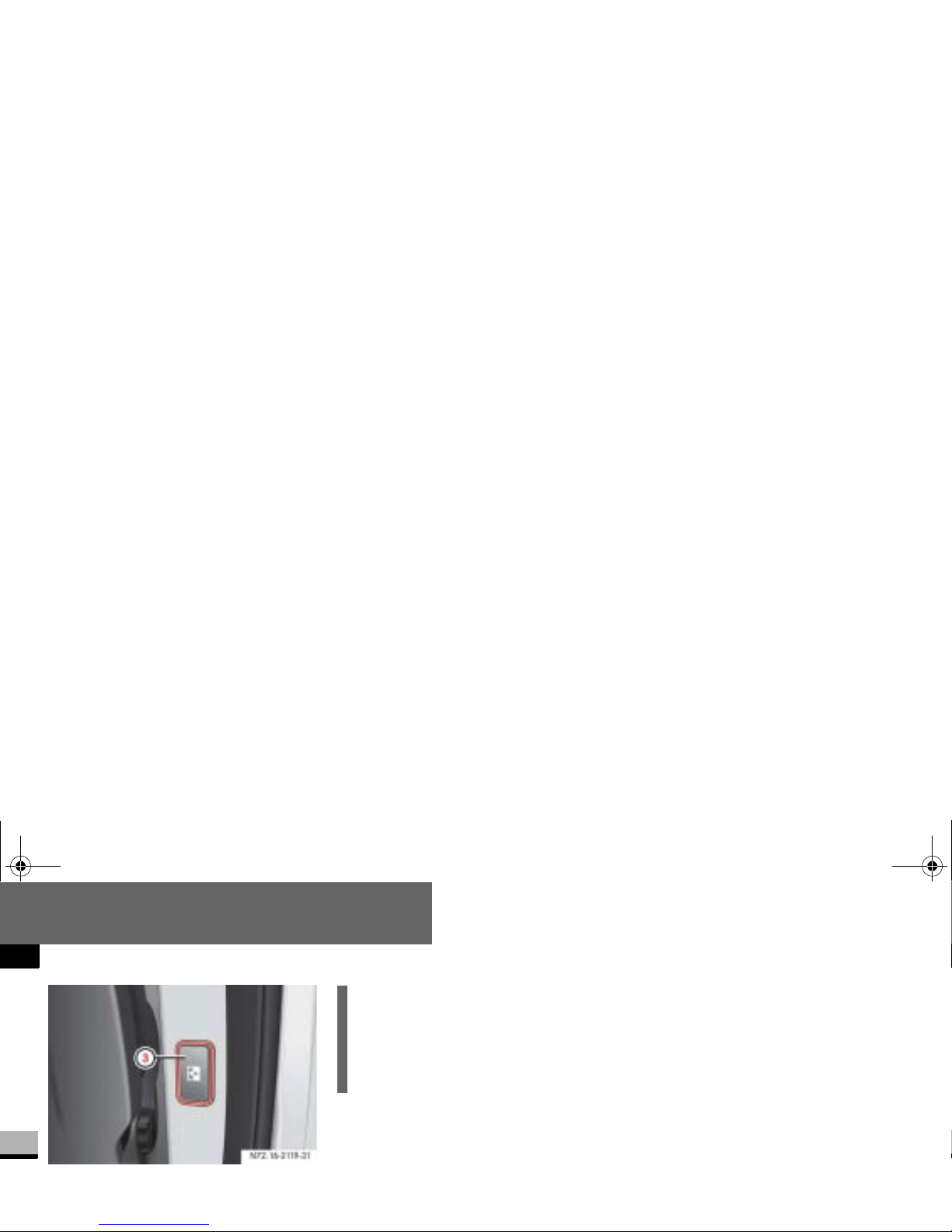
Controls in detail
Opening and closing
3
Sliding door switch in the doorway (B-pillar)
To unlock the sliding door from in-
side:
press lower part of the central
locking switch on the center console
(
page 104).
The indicator lamp in the switch goes
To open the sliding door: br i efly
press lower part
2 of the switch on
the center console or briefly press
switch
3 in the doorway.
The indicator lamp in the switch flashes. The sliding door opens.
To close the sliding door: briefly
press uppe r pa rt
1 of the switch on
the center console or briefly press
switch
3 in the doorway.
The indicator lamp in the switch
N72.16-2119-31
i
On vehicles with a partition, the
switch is located on the partition
near the doorway level with the inside door handle.
nf_BA.book Page 94 Friday, January 25, 2008 3:53 PM
Page 97
Controls in detail
Opening and closing
3
To stop the sliding door: press lo-
wer/upper part of the switch on the
center console or press switch
3 in
the doorway.
The sliding door stops.
To lock the sliding door from in-
side:
press lower part of the central
locking switch on the center console
(
page 104).
The indicator lamp in the switch comes on.
Proceed as follows in the event of unfavorable operating conditions, e.g. frost,
ice or heavy soiling:
To open the sliding door: press
lower part
2 of the switch on the
center console
or press and ho ld
switch
3 in the doorway.
The indicator lamp in the switch
flashes. The sliding door unlocks and
opens, and a signal sounds.
To close the sliding door: press up-
The indicator lamp in the switch
flashes. The sliding door closes and a
signal sounds.
Release the switch .
The sliding door stops.
To stop the sliding door: press lo-
wer/upper part of the switch on the
center console or press switch
3 in
the doorway.
The sliding door stops.
To lock the sliding door from in-
nf_BA.book Page 95 Friday, January 25, 2008 3:53 PM
Page 98
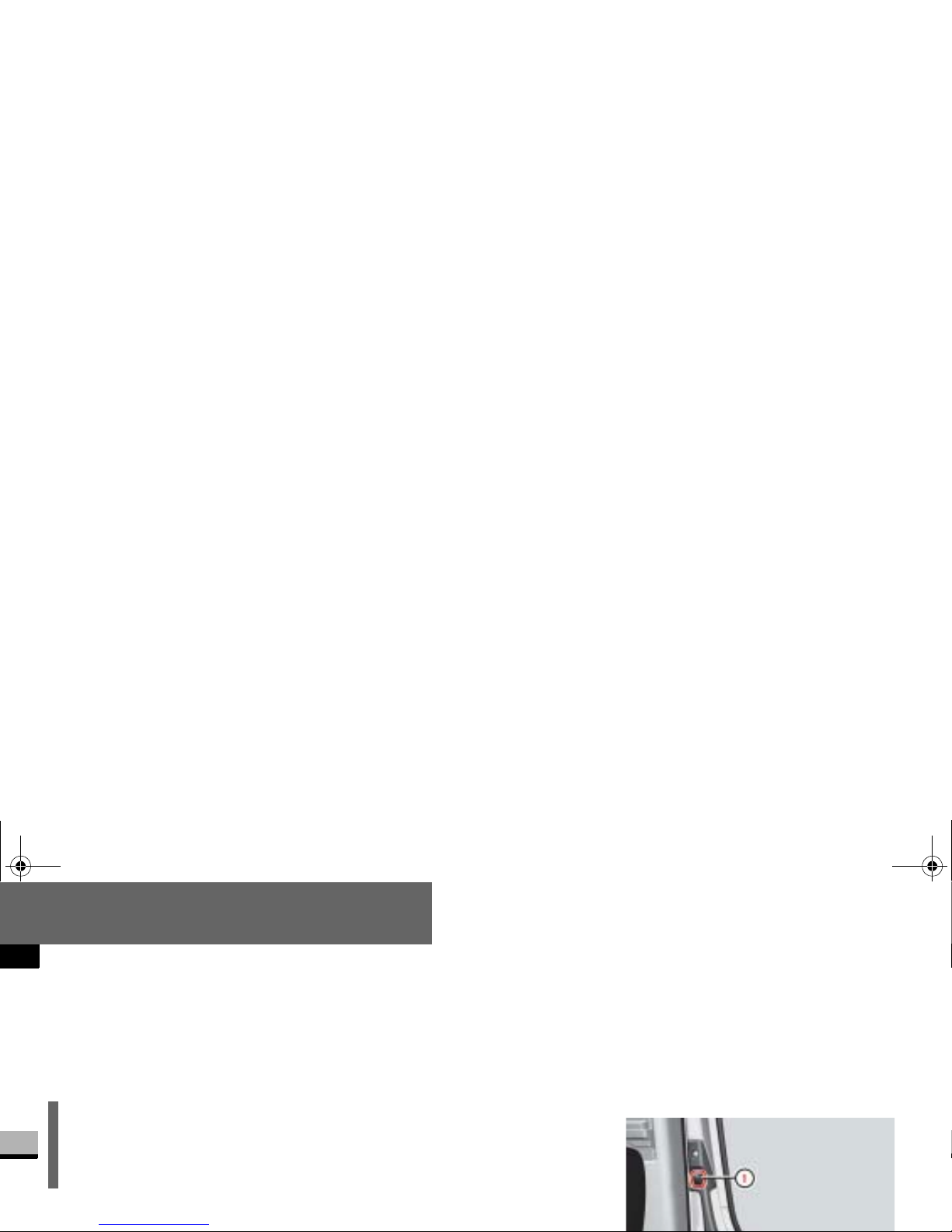
Controls in detail
Opening and closing
3
The indicator lamp in the switch
comes on.
or
Press the locki ng kno b o f t he sli din g
door down (
page 91).
The sliding door can jam under unfavor-
Press and hold lower part 2 of the
switch on the center console or press
and hold switch
3
in the door wa y.
The indicator la mp in the switch
flashes. Th e sliding door opens.
Release the switch.
The sliding door stops.
To close the sliding door: press
and hold upper part
1 of the switch
on the center console or press and
hold switch
3 in the doorway.
The sliding door stops.
Opening/closing using the inside
and outside door handles
Observe the notes on anti-trap protection (
page 98).
i
The indicator lamp in the switch on
the center console lights up whenever the sliding door is open.
N72.16-2118-31
nf_BA.book Page 96 Friday, January 25, 2008 3:53 PM
Page 99
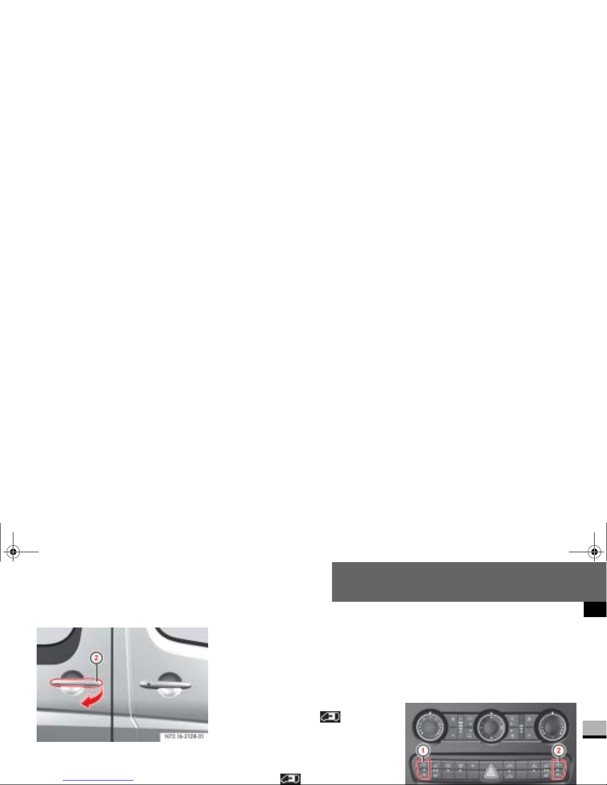
Controls in detail
Opening and closing
3
2 Outside door handle
Briefly press button 1 or pull out-
Press button 1 again or pull outside
door handle
2 again.
The sliding door stops.
Opening/closing with the remote
control
Press and hold the button for
more than half a second.
The sliding door unlocks and opens
or closes.
Press the button again.
Programming the remote control
If the vehicle is equipped with 2 sliding
doors, it is only possible to program the
remote control for one of the sliding
doors.
N72.16-2136-31
nf_BA.book Page 97 Friday, January 25, 2008 3:53 PM
Page 100
Controls in detail
Opening and closing
3
Make sure that the doors are closed.
Switch on the ignition ( page 111).
Press and hold the upper part of
relevant switch
1 or 2 on the cen-
ter console for 5 seconds.
The indicator lamp in the switch for
the sliding door concerned flashes
and a warning tone sounds three
times as confirmation.
Anti-trap protection
If the sliding door is obstructed during
the closing procedure, it opens fully
again.
Warning G
The anti-trap protection function does not
eliminate the p ossibility of f ingers or other
parts of the body being trapped against
the door frame and t herefore does not
eliminate the risk of injury.
Always make sure that nobody is within
the operating range of the sliding door.
i
The anti-trap protection is programmed to be le ss sensitive when
you press and hold the switch on the
center console or th e switch in the
doorway than when the door opens
of its own accord.
nf_BA.book Page 98 Friday, January 25, 2008 3:53 PM
 Loading...