


DN ENGINE 9 - 1
ENGINE
TABLE OF CONTENTS
page page
4.7L ENGINE.............................. 1
5.2L ENGINE............................. 86
4.7L ENGINE
TABLE OF CONTENTS
page page
DESCRIPTION AND OPERATION
ENGINE.................................2
ENGINE LUBRICATION SYSTEM..............3
CYLINDER BLOCK.........................5
CRANKSHAFT............................5
PISTON AND CONNECTING ROD .............5
CYLINDER HEAD..........................5
VALVE GUIDES ...........................5
VALVES.................................5
VALVE STEM SEAL ........................5
VALVE SPRING ...........................6
HYDRAULIC LASH ADJUSTER ...............6
TIMING DRIVE SYSTEM ....................6
CAMSHAFT ..............................6
ROCKER ARM............................6
CYLINDER HEAD COVER ...................6
OILPAN.................................7
STRUCTURAL DUST COVER ................7
INTAKE MANIFOLD ........................7
EXHAUST MANIFOLD ......................7
DIAGNOSIS AND TESTING
ENGINE DIAGNOSIS—INTRODUCTION.........7
SERVICE DIAGNOSIS—PERFORMANCE .......8
SERVICE DIAGNOSIS—MECHANICAL.........10
SERVICE DIAGNOSIS—LUBRICATION.........11
INTAKE MANIFOLD LEAKAGE DIAGNOSIS .....11
CYLINDER COMPRESSION PRESSURE TEST . . 11
CYLINDER HEAD GASKET FAILURE
DIAGNOSIS ...........................12
CYLINDER COMBUSTION PRESSURE
LEAKAGE TEST ........................12
ENGINE OIL LEAK INSPECTION .............13
REAR SEAL AREA LEAKS—INSPECTION ......14
HYDRAULIC LASH ADJUSTER NOISE
DIAGNOSIS ...........................14
CHECKING ENGINE OIL PRESSURE..........15
5.9L ENGINE............................ 135
SERVICE PROCEDURES
FORM-IN-PLACE GASKETS.................15
ENGINE OIL.............................16
REPAIR DAMAGED OR WORN THREADS......17
CYLINDER BORE—HONING ................18
HYDROSTATIC LOCK .....................18
VALVE SERVICE .........................19
ENGINE TIMING—VERIFICATION ............19
TIMING CHAIN—MEASURING WEAR .........22
PISTONS—FITTING.......................22
PISTON RINGS—FITTING ..................24
CONNECTING ROD BEARINGS—FITTING .....25
CRANKSHAFT MAIN BEARINGS .............27
REMOVAL AND INSTALLATION
ENGINE MOUNTS—LEFT AND RIGHT.........28
ENGINE MOUNT—REAR ...................29
STRUCTURAL COVER.....................30
ENGINE ASSEMBLY.......................31
INTAKE MANIFOLD .......................35
EXHAUST MANIFOLDS ....................36
CYLINDER HEAD COVER ..................38
ROCKER ARMS..........................40
CYLINDER HEADS........................41
VALVE SPRINGS AND SEALS ...............46
HYDRAULIC LASH ADJUSTER ..............46
CRANKSHAFT DAMPER ...................47
TIMING CHAIN COVER ....................48
TIMING CHAIN AND SPROCKETS ............49
IDLER SHAFT—TIMING DRIVE ..............55
CAMSHAFTS—IN VEHICLE .................56
CRANKSHAFT MAIN BEARINGS .............61
OIL PAN 4X2 VEHICLE.....................61
OIL PAN 4X4 VEHICLE.....................64
PISTON AND CONNECTING ROD ............65
CRANKSHAFT ...........................67
FLEXPLATE .............................69
9 - 2 4.7L ENGINE DN
OIL PUMP ..............................69
ENGINE OIL PRESSURE SENDING UNIT ......70
CRANKSHAFT OIL SEAL—FRONT............70
CRANKSHAFT OIL SEAL—REAR.............73
ENGINE CORE PLUGS ....................74
DISASSEMBLY AND ASSEMBLY
OIL PUMP ..............................74
CLEANING AND INSPECTION
INTAKE MANIFOLD .......................75
EXHAUST MANIFOLD .....................75
DESCRIPTION AND OPERATION
ENGINE
DESCRIPTION
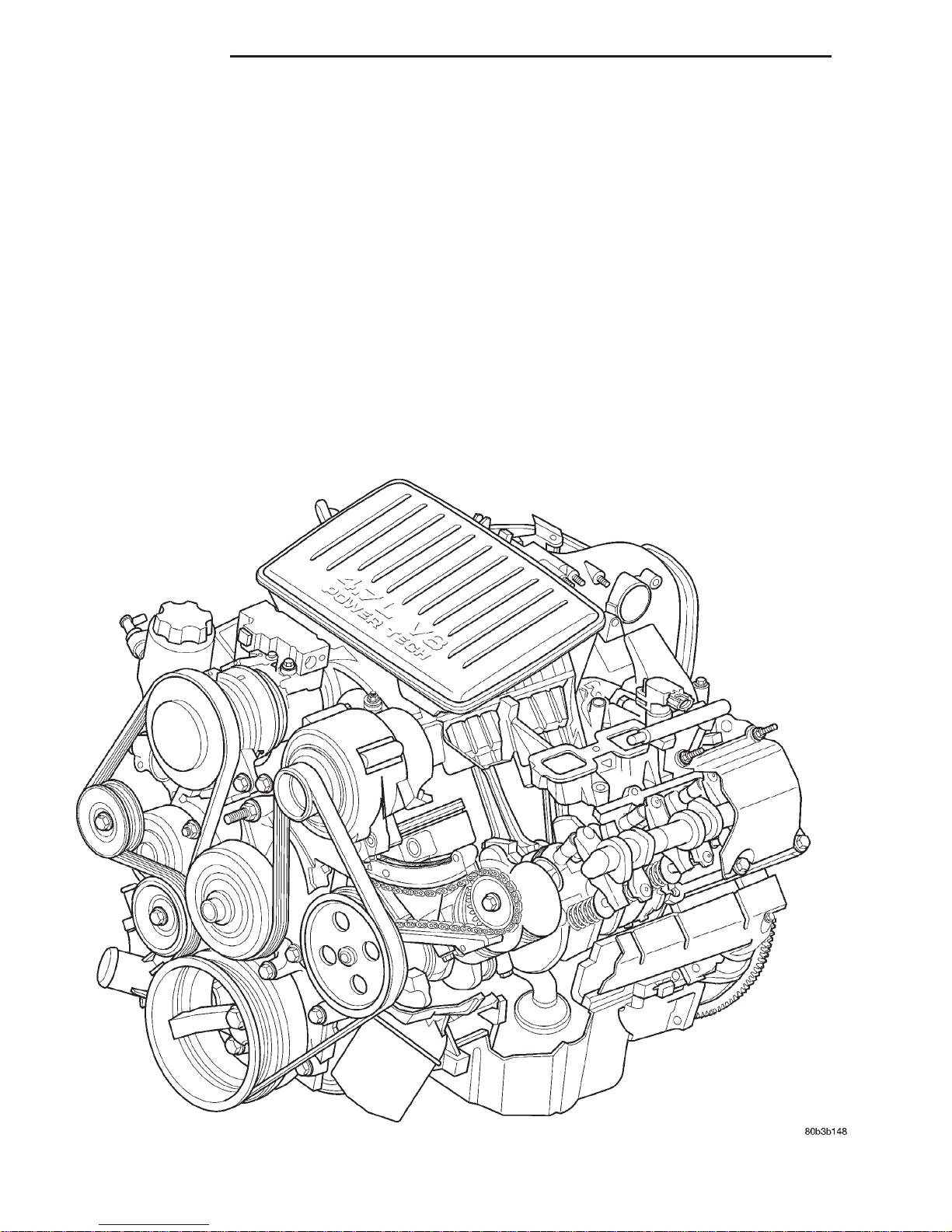
The 4.7 liter (287 CID) eight-cylinder engine is an
90° single overhead camshaft engine. The cast iron
CYLINDER HEADS........................75
PISTON AND CONNECTING ROD ............76
OILPAN................................76
OIL PUMP ..............................76
CYLINDER BLOCK........................76
SPECIFICATIONS
4.7L ENGINE ............................78
TORQUE ...............................81
SPECIAL TOOLS
4.7L ENGINE ............................82
cylinder block is made up of two different components; the first component is the cylinder bore and
upper block, the second component is the bedplate
that comprises the lower portion of the cylinder block
and houses the lower half of the crankshaft main
bearings. The cylinders are numbered from front to
rear with the left bank being numbered 1,3,5 and 7,
and the right bank being numbered 2,4,6 and 8. The

DN 4.7L ENGINE 9 - 3
DESCRIPTION AND OPERATION (Continued)
firing order is 1–8–4–3–6–5–7–2. The engine serial
number is located at the right front side of the
engine block (Fig. 1)
ENGINE LUBRICATION SYSTEM
DESCRIPTION
The lubrication system (Fig. 2) is a full flow filtra-
tion pressure feed type.
OPERATION
Oil from the oil pan is pumped by a gerotor type oil
pump directly mounted to the crankshaft nose. Oil
pressure is controlled by a relief valve mounted
inside the oil pump housing. For lubrication flow
refer to (Fig. 2).
The camshaft exhaust valve lobes and rocker arms
are lubricated through a small hole in the rocker
arm; oil flows through the lash adjuster then through
the rocker arm and onto the camshaft lobe. Due to
the orentation of the rocker arm, the camshaft intake
lobes are not lubed in the same manner as the
exhaust lobes. The intake lobes are lubed through
internal passages in the camshaft. Oil flows through
a bore in the number 3 camshaft bearing bore, and
as the camshaft turns, a hole in the camshaft aligns
with the hole in the camshaft bore allowing engine
oil to enter the camshaft tube. The oil then exits
through 1.6mm (0.063 in.) holes drilled into the
1 – VEHICLE VIN NUMBER LOCATION
2 – CYLINDER BLOCK RIGHT HAND SIDE
3 – CYLINDER BORE #2
intake lobes, lubricating the lobes and the rocker
arms.
Fig. 1 Engine Identification Location.
ENGINE LUBRICATION FLOW CHART—BLOCK: TABLE 1
FROM TO
Oil Pickup Tube Oil Pump
Oil Pump Oil Filter
Oil Filter Block Main Oil Gallery
Block Main Oil Gallery 1. Crankshaft Main Journal
2. Left Cylinder Head*
3. Right Cylinder Head*
Crankshaft Main Journals Crankshaft Rod Journals
Crankshaft Number One Main Journal 1.Front Timing Chain Idler Shaft
2. Both Secondary Chain Tensioners
Left Cylinder Head See Table 2
Right Cylinder Head See Table 2
* The cylinder head
gaskets have an oil restricter to control oil flow to the cylinder heads.

9 - 4 4.7L ENGINE DN
DESCRIPTION AND OPERATION (Continued)
1 – LEFT CYLINDER HEAD OIL GALLERY
2 – OIL PRESSURE SENSOR LOCATION
3 – TO LEFT CYLINDER HEAD
4 – OIL FEED TO IDLER SHAFT
5 – OIL PUMP OUTLET TO BLOCK
6 – OIL PUMP
Fig. 2 Engine Oil Lubrication System
7 – TO CRANKSHAFT MAIN JOURNALS
8 – RIGHT CYLINDER HEAD OIL GALLERY
9 – TO RIGHT CYLINDER HEAD
10 – CYLINDER BLOCK MAIN GALLERY
11 – OIL FEED TO BOTH SECONDARY TENSIONERS
DN 4.7L ENGINE 9 - 5
2000 DN Service Manual
DESCRIPTION AND OPERATION (Continued)
ENGINE LUBRICATION FLOW CHART—CYLINDER HEADS: TABLE 2
FROM TO
Cylinder Head Oil Port (in bolt hole) Diagonal Cross Drilling to Main Oil Gallery
Main Oil Gallery (drilled through head from rear to front)
Base of Camshaft Towers Vertical Drilling Through Tower to Camshaft Bearings**
Lash Adjuster Towers Diagonal Drillings to Hydraulic Lash Adjuster Pockets
** The number three camshaft bearing journal feeds oil into the hollow camshaft tubes. Oil is routed to the intake
lobes, which have oil passages drilled into them to lubricate the rocker arms.
1. Base of Camshaft Towers
2. Lash Adjuster Towers
Publication No. 81-370-0016
TSB 26-12-99 December, 1999
CYLINDER BLOCK
DESCRIPTION
The cylinder block is made of cast iron. The block
is a closed deck design with the left bank forward. To
provide high rigidity and improved NVH an
enhanced compacted graphite bedplate is bolted to
the block. The block design allows coolant flow
between the cylinders bores, and an internal coolant
bypass to a single poppet inlet thermostat is included
in the cast aluminum front cover.
CRANKSHAFT
DESCRIPTION
The crankshaft is constructed of nodular cast iron.
The crankshaft is a crosshaped four throw design
with eight counterweights for balancing purposes.
The crankshaft is supported by five select main bearings with the number three serving as the thrust
washer location. The main journals of the crankshaft
are cross drilled to improve rod bearing lubrication.
The number eight counterweight has provisions for
crankshaft position sensor target wheel mounting.
The select fit main bearing markings are located on
the rear side of the target wheel. The crankshaft oil
seals are one piece design. The front oil seal is
retained in the timing chain cover, and the rear seal
is pressed in to a bore formed by the cylinder block
and the bedplate assembly.
LATE BUILD
The pistons are made of high strength aluminum
alloy. The top ring groove and crown are Not anodized, instead the top ring is coated with an anti-scuff
coating to reduce friction on the top ring. The piston
skirts are coated with a solid lubricant (Molykote) to
reduce friction and provide scuff resistance. The connecting rods are made of forged powdered metal,
with a “fractured cap” design. A pressed fit piston pin
is used to attach the piston and connecting rod.
CYLINDER HEAD
DESCRIPTION
The cylinder heads are made of an aluminum alloy.
The cylinder head features two valves per cylinder
with pressed in powdered metal valve guides. The
cylinder heads also provide enclosures for the timing
chain drain, necessitating unique left and right cylinder heads.
VALVE GUIDES
DESCRIPTION
The valve guides are made of powered metal and
are pressed into the cylinder head. The guides are
not replaceable or serviceable, and valve guide reaming is not recommended. If the guides are worn
beyond acceptable limits, replace the cylinder heads.
PISTON AND CONNECTING ROD
DESCRIPTION
CAUTION: Do not use a metal stamp to mark connecting rods as damage may result, instead use ink
or a scratch awl.
EARLY BUILD
The pistons are made of a high strength aluminum
alloy with an anodized top ring groove and crown. Piston
skirts are coated with a solid lubricant (Molykote) to
reduce friction and provide scuff resistance. The connecting rods are made of forged powdered metal, with a
“fractured cap” design. A pressed fit piston pin is used to
attach the piston and connecting rod.
VALVES
DESCRIPTION
The valves are made of heat resistant steel and
have chrome plated stems to prevent scuffing. Each
valve is actuated by a roller rocker arm which pivots
on a stationary lash adjuster. All valves use three
bead lock keepers to retain the springs and promote
valve rotation.
VALVE STEM SEAL
DESCRIPTION
The valve stem seals are made of rubber and incorporate an integral steel valve spring seat. The integral garter spring maintains consistent lubrication
control to the valve stems.

9 - 6 4.7L ENGINE DN
DESCRIPTION AND OPERATION (Continued)
VALVE SPRING
DESCRIPTION
The valve springs are made from high strength
chrome silicon steel. The springs are common for
intake and exhaust applications. The valve spring
seat is integral with the valve stem seal, which is a
positive type seal to control lubrication.
HYDRAULIC LASH ADJUSTER
DESCRIPTION
Valve lash is controlled by hydraulic lash adjusters
that are stationary mounted in the cylinder heads.
The lash adjusters have a hole in the ball plunger
that feeds oil through the rocker arm squirt holes for
rocker arm roller and camshaft lobe lubrication.
TIMING DRIVE SYSTEM
DESCRIPTION
The timing drive system has been designed to provide quiet performance and reliability to support a
non-free wheeling engine. Specifically the intake
valves are non-free wheeling and can be easily damaged with forceful engine rotation if camshaft-tocrankshaft timing is incorrect. The timing drive
system consists of a primary chain and two secondary timing chain drives.
OPERATION
The primary timing chain is a single inverted tooth
type. The primary chain drives the large fifty tooth
idler sprocket directly from a 25 tooth crankshaft
sprocket. Primary chain motion is controlled by a
pivoting leaf spring tensioner arm and a fixed guide.
The arm and the guide both use nylon plastic wear
faces for low friction and long wear. The primary
chain receives oil splash lubrication from the secondary chain drive and oil pump leakage. The idler
sprocket assembly connects the primary and secondary chain drives. The idler sprocket assembly consists of two integral thirty tooth sprockets and a fifty
tooth sprocket that is splined to the assembly. The
spline joint is a non – serviceable press fit anti rattle
type. A spiral ring is installed on the outboard side of
the fifty tooth sprocket to prevent spline disengagement. The idler sprocket assembly spins on a stationary idler shaft. The idler shaft is press-fit into the
cylinder block. A large washer on the idler shaft bolt
and the rear flange of the idler shaft are used to control sprocket thrust movement. Pressurized oil is
routed through the center of the idler shaft to provide lubrication for the two bushings used in the
idler sprocket assembly.
There are two secondary drive chains, both are
inverted tooth type, one to drive the camshaft in each
SOHC cylinder head. There are no shaft speed
changes in the secondary chain drive system. Each
secondary chain drives a thirty tooth cam sprocket
directly from the thirty tooth sprocket on the idler
sprocket assembly. A fixed chain guide and a hydraulic oil damped tensioner are used to maintain tension
in each secondary chain system. The hydraulic tensioners for the secondary chain systems are fed pressurized oil from oil reservoir pockets in the block.
Each tensioner also has a mechanical ratchet system
that limits chain slack if the tensioner piston bleeds
down after engine shut down. The tensioner arms
and guides also utilize nylon wear faces for low friction and long wear. The secondary timing chains
receive lubrication from a small orifice in the tensioners. This orifice is protected from clogging by a
fine mesh screen which is located on the back of the
hydraulic tensioners.
CAMSHAFT
DESCRIPTION
The camshafts consist of powdered metal steel
lobes which are sinter-bonded to a steel tube. A steel
post or nose piece is friction-welded to the steel camshaft tube. Five bearing journals are machined into
the camshaft, four on the steel tube and one on the
steel nose piece. Camshaft end play is controlled by
two thrust walls that border the nose piece journal.
Engine oil enters the hollow camshafts at the third
journal and lubricates every intake lobe rocker
through a drilled passage in the intake lobe.
ROCKER ARM
DESCRIPTION
The rocker arms are steel stampings with an integral roller bearing. The rocker arms incorporate a 2.8
mm (0.11 inch) oil hole in the lash adjuster socket for
roller and camshaft lubrication.
CYLINDER HEAD COVER
DESCRIPTION
The cylinder head covers are made of die cast magnesium, and are not interchangeable from side-toside. It is imperative that nothing rest on the
cylinder head covers. Prolonged contact with other
items may wear a hole in the cylinder head cover.

DN 4.7L ENGINE 9 - 7
DESCRIPTION AND OPERATION (Continued)
OIL PAN
DESCRIPTION
The engine oil pan is made of laminated steel and
has a single plane sealing surface. The sandwich
style oil pan gasket has an integrated windage tray
and steel carrier. The sealing area of the gasket is
molded with rubber and is designed to be reused as
long as the gasket is not cut, torn or ripped.
STRUCTURAL DUST COVER
DESCRIPTION
The structural dust cover is made of die cast aluminum and joins the lower half of the transmission
bell housing to the engine bedplate.
OPERATION
The structural cover provides additional powertrain stiffness and reduces noise and vibration.
INTAKE MANIFOLD
DESCRIPTION
The intake manifold is made of a composite material and features long runners which maximizes low
end torque. The intake manifold uses single plane
sealing which consist of eight individual press in
place port gaskets to prevent leaks. Eight studs and
two bolts are used to fasten the intake to the head.
EXHAUST MANIFOLD
mance. The exhaust manifolds are made of high
silicon molybdenum cast iron. A perforated core
graphite exhaust manifold gasket is used to improve
sealing to the cylinder head. The exhaust manifolds
are covered by a three layer laminated heat shield
for thermal protection and noise reduction. The heat
shields are fastened with a torque prevailing nut
that is backed off slightly to allow for the thermal
expansion of the exhaust manifold.
DIAGNOSIS AND TESTING
ENGINE DIAGNOSIS—INTRODUCTION
Engine diagnosis is helpful in determining the
causes of malfunctions not detected and remedied by
routine maintenance.
These malfunctions may be classified as either performance (e.g., engine idles rough and stalls) or
mechanical (e.g., a strange noise).
Refer to the Service Diagnosis—Performance chart
and the Service Diagnosis—Mechanical chart for possible causes and corrections of malfunctions. Refer to
Group 14, Fuel System for the fuel system diagnosis.
Additional tests and diagnostic procedures may be
necessary for specific engine malfunctions that can
not be isolated with the Service Diagnosis charts.
Information concerning additional tests and diagnosis is provided within the following diagnosis:
• Cylinder Compression Pressure Test.
• Cylinder Combustion Pressure Leakage Test.
• Engine Cylinder Head Gasket Failure Diagnosis.
• Intake Manifold Leakage Diagnosis.
DESCRIPTION
The exhaust manifolds are log style with a pat-
ented flow enhancing design to maximize perfor-

9 - 8 4.7L ENGINE DN
DIAGNOSIS AND TESTING (Continued)
SERVICE DIAGNOSIS—PERFORMANCE
CONDITION POSSIBLE CAUSE CORRECTION
ENGINE WILL NOT START 1. Weak battery 1. Charge or replace as necessary.
2. Corroded or loose battery
connections.
3. Faulty starter. 3. Refer to Group 8A, Battery/
4. Moisture on ignition wires and
distributor cap.
5. Faulty ignition cables. 5. Replace as necessary.
6. Faulty coil or control unit. 6. Refer to Group 8D, Ignition
7. Incorrect spark plug gap. 7. Refer to Group 8D, Ignition
8. Incorrect ignition timing. 8. Refer to Group 8D, Ignition
9. Dirt or water in fuel system. 9. Clean system and replace fuel
10. Faulty fuel pump, relay or
wiring.
ENGINE STALLS OR ROUGH IDLE 1. Idle speed set to low. 1. Refer to Group 14, Fuel System.
2. Idle mixture to lean or to rich. 2. Refer to Group 14, Fuel System.
3. Vacuum leak. 3. Inspect intake manifold and
4. Worn or burned distributor rotor. 4. Replace distributor rotor.
5. Incorrect ignition wiring. 5. Install correct wiring.
6. Faulty coil. 6. Refer to Group 8D, Ignition
7. EGR valve leaking. 7. Refer to Group 25, Emissions
8. Incorrect cam timing. 8. Refer to Valve Timing in this
2. Clean and tighten battery
connections. Apply a coat of light
mineral grease to the terminals.
Starter/ Charging System
Diagnostics.
4. Wipe wires and cap clean and
dry.
System.
System.
System.
filter.
10. Refer to Group 14, Fuel System.
vacuum hoses, repair or replace as
necessary.
System.
Control System.
section.

DN 4.7L ENGINE 9 - 9
DIAGNOSIS AND TESTING (Continued)
CONDITION POSSIBLE CAUSE CORRECTION
ENGINE LOSS OF POWER 1. Incorrect ignition timing. 1. Refer to Group 8D, Ignition
System.
2. Worn or burned distributor rotor. 2. Replace distributor rotor.
3. Worn distributor shaft. 3. Refer to Group 8D, Ignition
System.
4. Dirty or incorrectly gapped spark
plugs.
5. Dirt or water in fuel system. 5. Clean system and replace fuel
6. Faulty fuel pump. 6. Refer to Group 14, Fuel System.
7. Blown cylinder head gasket. 7. Replace cylinder head gasket.
8. Low compression. 8. Test compression, repair as
9. Burned, warped or pitted valves. 9. Replace as necessary.
10. Plugged or restricted exhaust
system.
11. Faulty ignition cables. 11. Replace as necessary.
12. Faulty coil. 12. Refer to Group 8D, Ignition
13. Incorrect cam timing. 13. Refer to Valve Timing in this
4. Refer to Group 8D, Ignition
System.
filter.
necessary.
10. Inspect and replace as
necessary.
System.
section.
ENGINE MISSES ON
ACCELERATION
ENGINE MISSES AT HIGH SPEED 1. Spark plugs dirty or incorrectly
1. Spark plugs dirty or incorrectly
gapped.
2. Incorrect ignition timing. 2. Refer to Group 8D, Ignition
3. Dirt in fuel system. 3. Clean fuel system.
4. Burned, warped or pitted valves. 4. Replcae as necessary.
5. Faulty coil. 5. Refer to Group 8D, Ignition
6. Incorrect cam timing. 6. Refer to Valve Timing in this
gapped.
2. Worn Distributor Shaft. 2. Refer to Group 8D, Ignition
3. Worn or burned distributor rotor. 3. Replace distributor rotor.
4. Faulty coil. 4. Refer to Group 8D, Ignition
5. Incorrect ignition timing. 5. Refer to Group 8D, Ignition
6. Dirt or water in fuel system. 6. Clean system and replace fuel
7. Incorrect cam timing. 7. Refer to Valve Timing in this
1. Refer to Group 8D, Ignition
System.
System.
System.
section.
1. Refer to Group 8D, Ignition
System.
System.
System.
System.
filter.
section.

9 - 10 4.7L ENGINE DN
DIAGNOSIS AND TESTING (Continued)
SERVICE DIAGNOSIS—MECHANICAL
CONDITION POSSIBLE CAUSES CORRECTIONS
NOISY VALVES 1. High or low oil level in
crankcase.
2. Thin or diluted oil. 2. Change oil and filter.
3. Low oil pressure. 3. Check oil pump, if Ok, check rod
4. Dirt in lash adjusters. 4. Clean lash adjusters.
5. Bent push rods. 5. Replace as necessary.
6. Worn rocker arms. 6. Replace as necessary.
7. Worn tappets 7. Replace as necessary.
8. Worn valve guides. 8. Refer to Valve Service in this
9. Excessive runout of valve seats
on valve faces.
CONNECTING ROD NOISE 1. Insufficient oil supply. 1. Refer to Group 0, Lubrication and
2. Low oil pressure. 2. Refer to Group 0, Lubrication and
3. Thin or diluted oil. 3. Change oil and filter.
4. Excessive bearing clearance. 4. Replace as necessary.
5. Connecting rod journal
out-of-round.
6. Misaligned connecting rods. 6. Replace bent connecting rods.
1. Refer to Group 0, Lubrication and
Maintenance.
and main bearings for excessive
wear.
section.
9. Service valves and valve seats.
Refer to Valve Service in this
section.
maintenance.
maintenance.
5. Service or replace crankshaft.
MAIN BEARING NOISE 1. Insufficient oil supply. 1. Refer to Group 0, Lubrication and
maintenance.
2. Low oil pressure. 2. Refer to Group 0, Lubrication and
maintenance.
3. Thin or diluted oil. 3. Change oil and filter.
4. Excessive bearing clearance. 4. Replace as necessary.
5. Excessive end play. 5. Check No. 3 main bearing for
wear on flanges.
6. Crankshaft journal out-of round. 6. Service or replace crankshaft.
7. Loose flywheel or torque
converter.
7. Tighten to correct torque

DN 4.7L ENGINE 9 - 11
DIAGNOSIS AND TESTING (Continued)
SERVICE DIAGNOSIS—LUBRICATION
CONDITION POSSIBLE CAUSES CORRECTION
OIL LEAKS 1. Gaskets and O-Rings. 1.
(a) Misaligned or damaged. (a) Replace as necessary.
(b) Loose fasteners, broken or
porous metal parts.
2. Crankshaft rear seal 2. Replace as necessary.
3. Crankshaft seal flange.
Scratched, nicked or grooved.
4. Oil pan flange cracked. 4. Replace oil pan.
5. Timing chain cover seal,
damaged or misaligned.
6. Scratched or damaged vibration
damper hub.
OIL PRESSURE DROP 1. Low oil level. 1. Check and correct oil level.
(b) Tighten fasteners, Repair or
replace metal parts.
3. Polish or replace crankshaft.
5. Replace seal.
6. Polish or replace damper.
2. Faulty oil pressure sending unit. 2. Replace sending unit.
3. Low oil pressure. 3. Check pump and bearing
4. Clogged oil filter. 4. Replace oil filter.
5. Worn oil pump. 5. Replace as necessary.
6. Thin or diluted oil. 6. Change oil and filter.
7. Excessive bearing clearance. 7. Replace as necessary.
8. Oil pump relief valve stuck. 8. Clean or replace relief valve.
9. Oil pump suction tube loose or
damaged.
OIL PUMPING AT RINGS; SPARK
PLUGS FOULING
1. Worn or damaged rings. 1. Hone cylinder bores and replace
2. Carbon in oil ring slots. 2. Replace rings.
3. Incorrect ring size installed. 3. Replace rings.
4. Worn valve guides. 4. Ream guides and replace valves.
5. Leaking intake gasket. 5. Replace intake gaskets.
6. Leaking valve guide seals. 6. Replace valve guide seals.
INTAKE MANIFOLD LEAKAGE DIAGNOSIS
An intake manifold air leak is characterized by
lower than normal manifold vacuum. Also, one or
more cylinders may not be functioning.
WARNING: USE EXTREME CAUTION WHEN THE
ENGINE IS OPERATING. DO NOT STAND IN A
DIRECT LINE WITH THE FAN. DO NOT PUT YOUR
HANDS NEAR THE PULLEYS, BELTS OR THE FAN.
DO NOT WEAR LOOSE CLOTHING.
(1) Start the engine.
clearance.
9. Replace as necessary.
rings.
(2) Spray a small stream of water at the suspected
leak area.
(3) If a change in RPM is observed the area of the
suspected leak has been found.
(4) Repair as required.
CYLINDER COMPRESSION PRESSURE TEST
The results of a cylinder compression pressure test
can be utilized to diagnose several engine malfunctions.
Ensure the battery is completely charged and the
engine starter motor is in good operating condition.

9 - 12 4.7L ENGINE DN
DIAGNOSIS AND TESTING (Continued)
Otherwise the indicated compression pressures may
not be valid for diagnosis purposes.
(1) Clean the spark plug recesses with compressed
air.
(2) Remove the spark plugs.
(3) Secure the throttle in the wide-open position.
(4) Disable the fuel system. (Refer to Group 14,
Fuel System for the correct procedure)
(5) Disconnect the ignition coil.
(6) Insert a compression pressure gauge and rotate
the engine with the engine starter motor for three
revolutions.
(7) Record the compression pressure on the 3rd
revolution. Continue the test for the remaining cylinders.
Refer to Engine Specifications for the correct
engine compression pressures.
CYLINDER HEAD GASKET FAILURE DIAGNOSIS
A cylinder head gasket leak can be located between
adjacent cylinders or between a cylinder and the
adjacent water jacket.
• Possible indications of the cylinder head gasket
leaking between adjacent cylinders are:
• Loss of engine power
• Engine misfiring
• Poor fuel economy
• Possible indications of the cylinder head gasket
leaking between a cylinder and an adjacent water
jacket are:
• Engine overheating
• Loss of coolant
• Excessive steam (white smoke) emitting from
exhaust
• Coolant foaming
CYLINDER-TO-CYLINDER LEAKAGE TEST
To determine if an engine cylinder head gasket is
leaking between adjacent cylinders, follow the procedures in Cylinder Compression Pressure Test in this
section. An engine cylinder head gasket leaking
between adjacent cylinders will result in approximately a 50–70% reduction in compression pressure.
CYLINDER-TO-WATER JACKET LEAKAGE TEST
WARNING: USE EXTREME CAUTION WHEN THE
ENGINE IS OPERATING WITH COOLANT PRESSURE CAP REMOVED.
VISUAL TEST METHOD
With the engine cool, remove the coolant pressure
cap. Start the engine and allow it to warm up until
thermostat opens.
If a large combustion/compression pressure leak
exists, bubbles will be visible in the coolant.
COOLING SYSTEM TESTER METHOD
WARNING: WITH COOLING SYSTEM TESTER IN
PLACE, PRESSURE WILL BUILD UP FAST. EXCESSIVE PRESSURE BUILT UP, BY CONTINUOUS
ENGINE OPERATION, MUST BE RELEASED TO A
SAFE PRESSURE POINT. NEVER PERMIT PRESSURE TO EXCEED 138 kPa (20 psi).
Install Cooling System Tester 7700 or equivalent to
pressure cap neck. Start the engine and observe the
tester’s pressure gauge. If gauge pulsates with every
power stroke of a cylinder a combustion pressure
leak is evident.
CHEMICAL TEST METHOD
Combustion leaks into the cooling system can also
be checked by using Bloc-Chek Kit C-3685-A or
equivalent. Perform test following the procedures
supplied with the tool kit.
CYLINDER COMBUSTION PRESSURE LEAKAGE
TEST
The combustion pressure leakage test provides an
accurate means for determining engine condition.
Combustion pressure leakage testing will detect:
• Exhaust and intake valve leaks (improper seat-
ing).
• Leaks between adjacent cylinders or into water
jacket.
• Any causes for combustion/compression pressure
loss.
(1) Check the coolant level and fill as required. DO
NOT install the radiator cap.
(2) Start and operate the engine until it attains
normal operating temperature, then turn the engine
OFF.
(3) Remove the spark plugs.
(4) Remove the oil filler cap.
(5) Remove the air cleaner.
Calibrate the tester according to the manufacturer’s
(6)
instructions. The shop air source for testing should maintain 483 kPa (70 psi) minimum, 1,379 kPa (200 psi) maximum and 552 kPa (80 psi) recommended.
(7) Perform the test procedures on each cylinder
according to the tester manufacturer’s instructions.
While testing, listen for pressurized air escaping
through the throttle body, tailpipe and oil filler cap
opening. Check for bubbles in the radiator coolant.
All gauge pressure indications should be equal,
with no more than 25% leakage.
FOR EXAMPLE: At 552 kPa (80 psi) input pressure, a minimum of 414 kPa (60 psi) should be maintained in the cylinder.
Refer to the Cylinder Combustion Pressure Leakage Test Diagnosis chart.
DN 4.7L ENGINE 9 - 13
DIAGNOSIS AND TESTING (Continued)
CYLINDER COMBUSTION PRESSURE LEAKAGE DIAGNOSIS CHART
CONDITION POSSIBLE CAUSE CORRECTION
AIR ESCAPES THROUGH
THROTTLE BODY
AIR ESCAPES THROUGH
TAILPIPE
AIR ESCAPES THROUGH
RADIATOR
MORE THAN 50% LEAKAGE
FROM ADJACENT CYLINDERS
MORE THAN 25% LEAKAGE AND
AIR ESCAPES THROUGH OIL
FILLER CAP OPENING ONLY
Intake valve bent, burnt, or not
seated properly
Exhaust valve bent, burnt, or not
seated properly
Head gasket leaking or cracked
cylinder head or block
Head gasket leaking or crack in
cylinder head or block between
adjacent cylinders
Stuck or broken piston rings;
cracked piston; worn rings and/or
cylinder wall
Inspect valve and valve seat.
Reface or replace, as necessary
Inspect valve and valve seat.
Reface or replace, as necessary
Remove cylinder head and inspect.
Replace defective part
Remove cylinder head and inspect.
Replace gasket, head, or block as
necessary
Inspect for broken rings or piston.
Measure ring gap and cylinder
diameter, taper and out-of-round.
Replace defective part as necessary
ENGINE OIL LEAK INSPECTION
Begin with a thorough visual inspection of the
engine, particularly at the area of the suspected leak.
If an oil leak source is not readily identifiable, the
following steps should be followed:
(1) Do not clean or degrease the engine at this
time because some solvents may cause rubber to
swell, temporarily stopping the leak.
(2) Add an oil soluble dye (use as recommended by
manufacturer). Start the engine and let idle for
approximately 15 minutes. Check the oil dipstick to
make sure the dye is thoroughly mixed as indicated
with a bright yellow color under a black light.
(3) Using a black light, inspect the entire engine
for fluorescent dye, particularly at the suspected area
of oil leak. If the oil leak is found and identified,
repair per service manual instructions.
(4) If dye is not observed, drive the vehicle at various speeds for approximately 24km (15 miles), and
repeat inspection.
(4) If the oil leak source is not positively
identified at this time, proceed with the air leak
detection test method.
Air Leak Detection Test Method
(1) Disconnect the breather cap to air cleaner hose
at the breather cap end. Cap or plug breather cap
nipple.
(2) Remove the PCV valve from the cylinder head
cover. Cap or plug the PCV valve grommet.
(3) Attach an air hose with pressure gauge and
regulator to the dipstick tube.
CAUTION: Do not subject the engine assembly to
more than 20.6 kpa (3 PSI) of test pressure.
(4) Gradually apply air pressure from 1 psi to 2.5
psi maximum while applying soapy water at the suspected source. Adjust the regulator to the suitable
test pressure that provide the best bubbles which
will pinpoint the leak source. If the oil leak is
detected and identified, repair per service manual
procedures.
(5) If the leakage occurs at the rear oil seal area,
refer to the section, Inspection for Rear Seal Area
Leak.
(6) If no leaks are detected, turn off the air supply
and remove the air hose and all plugs and caps.
Install the PCV valve and breather cap hose.
(7) Clean the oil off the suspect oil leak area using
a suitable solvent. Drive the vehicle at various
speeds approximately 24 km (15 miles). Inspect the
engine for signs of an oil leak by using a black light.
INSPECTION FOR REAR SEAL AREA LEAKS
Since it is sometimes difficult to determine the
source of an oil leak in the rear seal area of the
engine, a more involved inspection is necessary. The
following steps should be followed to help pinpoint
the source of the leak.
If the leakage occurs at the crankshaft rear oil seal
area:
(1) Disconnect the battery.
(2) Raise the vehicle.
(3) Remove torque converter or clutch housing
cover and inspect rear of block for evidence of oil.
Use a black light to check for the oil leak:
(a) Circular spray pattern generally indicates
seal leakage or crankshaft damage.
(b) Where leakage tends to run straight down,
possible causes are a porous block, distributor seal,
camshaft bore cup plugs oil galley pipe plugs, oil

9 - 14 4.7L ENGINE DN
DIAGNOSIS AND TESTING (Continued)
filter runoff, and main bearing cap to cylinder
block mating surfaces.
(4) If no leaks are detected, pressurize the crankcase as outlined in the, Inspection (Engine oil Leaks
in general)
CAUTION: Do not exceed 20.6 kPa (3 psi).
(5) If the leak is not detected, very slowly turn the
crankshaft and watch for leakage. If a leak is
detected between the crankshaft and seal while
slowly turning the crankshaft, it is possible the
crankshaft seal surface is damaged. The seal area on
the crankshaft could have minor nicks or scratches
that can be polished out with emery cloth.
CAUTION: Use extreme caution when crankshaft
polishing is necessary to remove minor nicks and
scratches. The crankshaft seal flange is especially
machined to complement the function of the rear oil
seal.
(6) For bubbles that remain steady with shaft
rotation, no further inspection can be done until disassembled.
REAR SEAL AREA LEAKS—INSPECTION
Since it is sometimes difficult to determine the
source of an oil leak in the rear seal area of the
engine, a more involved inspection is necessary. The
following steps should be followed to help pinpoint
the source of the leak.
If the leakage occurs at the crankshaft rear oil seal
area:
(1) Disconnect the battery.
(2) Raise the vehicle.
(3) Remove torque converter or clutch housing
cover and inspect rear of block for evidence of oil.
Use a black light to check for the oil leak:
(a) Circular spray pattern generally indicates
seal leakage or crankshaft damage.
(b) Where leakage tends to run straight down,
possible causes are a porous block, distributor seal,
camshaft bore cup plugs, oil galley pipe plugs, oil
filter runoff, and main bearing cap to cylinder
block mating surfaces. See Group 9, Engines, for
proper repair procedures of these items.
(4) If no leaks are detected, pressurized the crank-
case as outlined in the section, Inspection (Engine oil
Leaks in general)
CAUTION: Do not exceed 20.6 kPa (3 psi).
(5) If the leak is not detected, very slowly turn the
crankshaft and watch for leakage. If a leak is
detected between the crankshaft and seal while
slowly turning the crankshaft, it is possible the
crankshaft seal surface is damaged. The seal area on
the crankshaft could have minor nicks or scratches
that can be polished out with emery cloth.
CAUTION: Use extreme caution when crankshaft
polishing is necessary to remove minor nicks or
scratches. The crankshaft seal flange is specially
machined to complement the function of the rear oil
seal.
(6) For bubbles that remain steady with shaft
rotation, no further inspection can be done until disassembled. Refer to the service Diagnosis—Mechanical, under the Oil Leak row, for components
inspections on possible causes and corrections.
(7) After the oil leak root cause and appropriate
corrective action have been identified, Refer to Group
9, Engines—Crankshaft Rear Oil Seals, for proper
replacement procedures.
HYDRAULIC LASH ADJUSTER NOISE
DIAGNOSIS
A tappet-like noise may be produced from several
items. Check the following items.
(1) Engine oil level too high or too low. This may
cause aerated oil to enter the adjusters and cause
them to be spongy.
(2) Insufficient running time after rebuilding cylinder head. Low speed running up to 1 hour may be
required.
(3) Turn engine off and let set for a few minutes
before restarting. Repeat this several times after
engine has reached normal operating temperature.
(4) Low oil pressure.
(5) The oil restrictor in cylinder head gasket or the
oil passage to the cylinder head is plugged with
debris.
(6) Air ingested into oil due to broken or cracked
oil pump pick up.
(7) Worn valve guides.
(8) Rocker arm ears contacting valve spring
retainer.
(9) Rocker arm loose, adjuster stuck or at maximum extension and still leaves lash in the system.
(10) Faulty lash adjuster.
a. Check lash adjusters for sponginess while
installed in cylinder head and cam on camshaft at
base circle. Depress part of rocker arm over adjuster.
Normal adjusters should feel very firm. Spongy
adjusters can be bottomed out easily.
b. Remove suspected lash adjusters, and replace.
c. Before installation, make sure adjusters are at
least partially full of oil. This can be verified by little
or no plunger travel when lash adjuster is depressed.

DN 4.7L ENGINE 9 - 15
DIAGNOSIS AND TESTING (Continued)
CHECKING ENGINE OIL PRESSURE
(1) Remove oil pressure sending unit (Fig. 3) and
install gauge assembly C-3292.
Fig. 3 Oil Pressure Sending Unit
1 – BELT
2 – OIL PRESSURE SENSOR
3 – OIL FILTER
4 – ELEC. CONNECTOR
(2) Run engine until thermostat opens.
(3) Oil Pressure:
• Curb Idle—25 Kpa (4 psi) minimum
• 3000 rpm—170 - 550 KPa (25 - 80 psi)
(4) If oil pressure is 0 at idle, shut off engine.
Check for a clogged oil pick-up screen or a pressure
relief valve stuck open.
SERVICE PROCEDURES
FORM-IN-PLACE GASKETS
There are several places where form-in-place gaskets are used on the engine. DO NOT use form-in-
place gasket material unless specified. Care
must be taken when applying form-in-place gaskets.
Bead size, continuity and location are of great importance. Too thin a bead can result in leakage while too
much can result in spill-over. A continuous bead of
the proper width is essential to obtain a leak-free
joint.
Two types of form-in-place gasket materials are
used in the engine area (Mopar Silicone Rubber
Adhesive Sealant and Mopar Gasket Maker). Each
have different properties and cannot be used interchangeably.
MOPAR SILICONE RUBBER ADHESIVE SEALANT
Mopar Silicone Rubber Adhesive Sealant, normally
black in color, is available in 3 ounce tubes. Moisture
in the air causes the sealant material to cure. This
material is normally used on flexible metal flanges.
It has a shelf life of a year and will not properly cure
if over aged. Always inspect the package for the expiration date before use.
MOPAR GASKET MAKER
Mopar Gasket Maker, normally red in color, is
available in 6 cc tubes. This anaerobic type gasket
material cures in the absence of air when squeezed
between smooth machined metallic surfaces. It will
not cure if left in the uncovered tube. DO NOT use
on flexible metal flanges.
SURFACE PREPARATION
Parts assembled with form-in-place gaskets may be
disassembled without unusual effort. In some
instances, it may be necessary to lightly tap the part
with a mallet or other suitable tool to break the seal
between the mating surfaces. A flat gasket scraper
may also be lightly tapped into the joint but care
must be taken not to damage the mating surfaces.
Scrape or wire brush all gasket surfaces to remove
all loose material. Inspect stamped parts to ensure
gasket rails are flat. Flatten rails with a hammer on
a flat plate, if required. Gasket surfaces must be free
of oil and dirt. Make sure the old gasket material is
removed from blind attaching holes.
GASKET APPLICATION
Assembling parts using a form-in-place gasket
requires care.
Mopar Silicone Rubber Adhesive Sealant should be
applied in a continuous bead approximately 3 mm
(0.12 inch) in diameter. All mounting holes must be
circled. For corner sealing,a3or6mm(1/8 or 1/4
inch) drop is placed in the center of the gasket contact area. Uncured sealant may be removed with a
shop towel. Components should be torqued in place
while the sealant is still wet to the touch (within 10
minutes). The use of a locating dowel is recommended during assembly to prevent smearing the
material off location.
Mopar Gasket Maker should be applied sparingly
to one gasket surface. The sealant diameter should
be 1.00 mm (0.04 inch) or less. Be certain the material surrounds each mounting hole. Excess material
can easily be wiped off. Components should be
torqued in place within 15 minutes. The use of a

9 - 16 4.7L ENGINE DN
SERVICE PROCEDURES (Continued)
locating dowel is recommended during assembly to
prevent smearing the material off location.
ENGINE OIL
WARNING: NEW OR USED ENGINE OIL CAN BE
IRRITATING TO THE SKIN. AVOID PROLONGED OR
REPEATED SKIN CONTACT WITH ENGINE OIL.
CONTAMINANTS IN USED ENGINE OIL, CAUSED BY
INTERNAL COMBUSTION, CAN BE HAZARDOUS TO
YOUR HEALTH. THOROUGHLY WASH EXPOSED
SKIN WITH SOAP AND WATER. DO NOT WASH
SKIN WITH GASOLINE, DIESEL FUEL, THINNER, OR
SOLVENTS, HEALTH PROBLEMS CAN RESULT. DO
NOT POLLUTE, DISPOSE OF USED ENGINE OIL
PROPERLY.
ENGINE OIL SPECIFICATION
CAUTION: Do not use non-detergent or straight
mineral oil when adding or changing crankcase
lubricant. Engine failure can result.
API SERVICE GRADE CERTIFIED
Use an engine oil that is API Service Grade Certified. MOPARt provides engine oils that conform to
this service grade.
ENERGY CONSERVING OIL
An Energy Conserving type oil is recommended for
gasoline engines. The designation of ENERGY CONSERVING is located on the label of an engine oil container.
CONTAINER IDENTIFICATION
Standard engine oil identification notations have
been adopted to aid in the proper selection of engine
oil. The identifying notations are located on the label
of engine oil plastic bottles and the top of engine oil
cans (Fig. 5).
Fig. 5 Engine Oil Container Standard Notations
OIL LEVEL INDICATOR (DIPSTICK)
The engine oil level indicator is located at the right
rear of the engine on the 4.7L engines. (Fig. 6).
SAE VISCOSITY
An SAE viscosity grade is used to specify the viscosity of engine oil. Use only engine oils with multiple viscosities such as 5W-30 or 10W-30 in the 4.7L
engines. These are specified with a dual SAE viscosity grade which indicates the cold-to-hot temperature
viscosity range. Select an engine oil that is best
suited to your particular temperature range and variation (Fig. 4).
Fig. 4 Temperature/Engine Oil Viscosity—4.7L
Engine
Fig. 6 Engine Oil Dipstick 4.7L Engine
1 – TRANSMISSION DIPSTICK
2 – ENGINE OIL DIPSTICK
3 – ENGINE OIL FILL CAP

DN 4.7L ENGINE 9 - 17
SERVICE PROCEDURES (Continued)
CRANKCASE OIL LEVEL INSPECTION
CAUTION: Do not overfill crankcase with engine oil,
pressure loss or oil foaming can result.
Inspect engine oil level approximately every 800
kilometers (500 miles). Unless the engine has exhibited loss of oil pressure, run the engine for about five
minutes before checking oil level. Checking engine oil
level on a cold engine is not accurate.
To ensure proper lubrication of an engine, the
engine oil must be maintained at an acceptable level.
The acceptable levels are indicated between the ADD
and SAFE marks on the engine oil dipstick.
(1) Position vehicle on level surface.
(2) With engine OFF, allow approximately ten minutes for oil to settle to bottom of crankcase, remove
engine oil dipstick.
(3) Wipe dipstick clean.
(4) Install dipstick and verify it is seated in the
tube.
(5) Remove dipstick, with handle held above the
tip, take oil level reading.
(6) Add oil only if level is below the ADD mark on
dipstick.
OIL FILTER REMOVAL
(1) Position a drain pan under the oil filter.
(2) Using a suitable oil filter wrench loosen filter.
(3) Rotate the oil filter counterclockwise (Fig. 7) to
remove it from the cylinder block oil filter boss.
ENGINE OIL CHANGE
Change engine oil at mileage and time intervals
described in Maintenance Schedules.
Run engine until achieving normal operating temperature.
(1) Position the vehicle on a level surface and turn
engine off.
(2) Hoist and support vehicle on safety stands.
(3) Remove oil fill cap.
(4) Place a suitable drain pan under crankcase
drain.
(5) Remove drain plug from crankcase and allow
oil to drain into pan. Inspect drain plug threads for
stretching or other damage. Replace drain plug if
damaged.
(6) Install drain plug in crankcase.
(7) Lower vehicle and fill crankcase with specified
type and amount of engine oil described in this section.
(8) Install oil fill cap.
(9) Start engine and inspect for leaks.
(10) Stop engine and inspect oil level.
ENGINE OIL FILTER CHANGE
Fig. 7 Oil Filter—4.7L Engine
1 – ENGINE OIL FILTER
(4) When filter separates from cylinder block oil
filter boss, tip gasket end upward to minimize oil
spill. Remove filter from vehicle.
(5) With a wiping cloth, clean the gasket sealing
surface of oil and grime.
OIL FILTER INSTALLATION
(1) Lightly lubricate oil filter gasket with engine
oil.
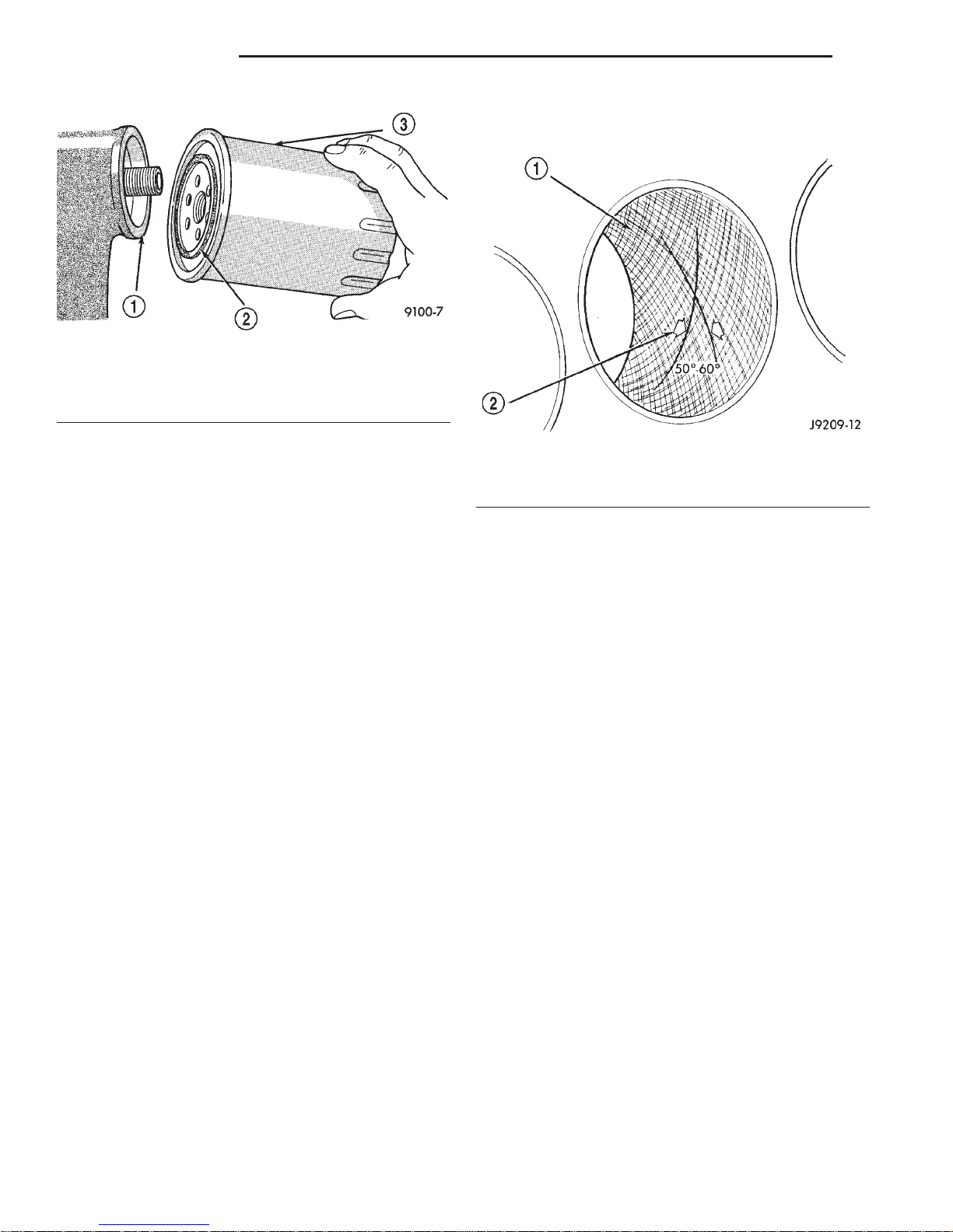
(2) Thread filter onto adapter nipple. When gasket
makes contact with sealing surface, (Fig. 8) hand
tighten filter one full turn, do not over tighten.
(3) Add oil, verify crankcase oil level and start
engine. Inspect for oil leaks.
USED ENGINE OIL DISPOSAL
Care should be exercised when disposing used
engine oil after it has been drained from a vehicle
engine. Refer to the WARNING at beginning of this
section.
FILTER SPECIFICATION
All engines are equipped with a high quality fullflow, disposable type oil filter. DaimlerChrysler Corporation recommends a Mopar or equivalent oil filter
be used.
REPAIR DAMAGED OR WORN THREADS
CAUTION: Be sure that the tapped holes maintain
the original center line.
9 - 18 4.7L ENGINE DN
SERVICE PROCEDURES (Continued)
The hone marks should INTERSECT at 50° to 60°
for proper seating of rings (Fig. 9).
Fig. 8 Oil Filter Sealing Surface—Typical
1 – SEALING SURFACE
2 – RUBBER GASKET
3 – OIL FILTER
Damaged or worn threads can be repaired. Essentially, this repair consists of:
• Drilling out worn or damaged threads.
• Tapping the hole with a special Heli-Coil Tap, or
equivalent.
• Installing an insert into the tapped hole to bring
the hole back to its original thread size.
CYLINDER BORE—HONING
Before honing, stuff plenty of clean shop towels
under the bores and over the crankshaft to keep
abrasive materials from entering the crankshaft
area.
(1) Used carefully, the Cylinder Bore Sizing Hone
C-823, equipped with 220 grit stones, is the best tool
for this job. In addition to deglazing, it will reduce
taper and out-of-round, as well as removing light
scuffing, scoring and scratches. Usually, a few strokes
will clean up a bore and maintain the required limits.
CAUTION: DO NOT use rigid type hones to remove
cylinder wall glaze.
(2) Deglazing of the cylinder walls may be done if
the cylinder bore is straight and round. Use a cylinder surfacing hone, Honing Tool C-3501, equipped
with 280 grit stones (C-3501-3810). about 20-60
strokes, depending on the bore condition, will be sufficient to provide a satisfactory surface. Using honing
oil C-3501-3880, or a light honing oil, available from
major oil distributors.
Fig. 9 Cylinder Bore Crosshatch Pattern
1 – CROSSHATCH PATTERN
2 – INTERSECTANGLE
(4) A controlled hone motor speed between 200 and
300 RPM is necessary to obtain the proper crosshatch angle. The number of up and down strokes per
minute can be regulated to get the desired 50° to 60°
angle. Faster up and down strokes increase the crosshatch angle.
(5) After honing, it is necessary that the block be
cleaned to remove all traces of abrasive. Use a brush
to wash parts with a solution of hot water and detergent. Dry parts thoroughly. Use a clean, white, lintfree cloth to check that the bore is clean. Oil the
bores after cleaning to prevent rusting.
HYDROSTATIC LOCK
When an engine is suspected of hydrostatic lock
(regardless of what caused the problem), follow the
steps below.
(1) Perform the Fuel Pressure Release Procedure
(refer to Group 14, Fuel System).
(2) Disconnect the battery negative cable.
(3) Inspect air cleaner, induction system and
intake manifold to ensure system is dry and clear of
foreign material.
(4) Place a shop towel around the spark plugs to
catch any fluid that may possibly be under pressure
in the cylinder head. Remove the plugs from the
engine.
CAUTION: DO NOT use engine or transmission oil,
mineral spirits, or kerosene.
(3) Honing should be done by moving the hone up
and down fast enough to get a crosshatch pattern.
CAUTION: DO NOT use the starter motor to rotate
the crankshaft. Severe damage could occur.
(5) With all spark plugs removed, rotate the crankshaft using a breaker bar and socket.

DN 4.7L ENGINE 9 - 19
SERVICE PROCEDURES (Continued)
(6) Identify the fluid in the cylinders (i.e. coolant,
fuel, oil, etc.).
(7) Make sure all fluid has been removed from the
cylinders.
(8) Repair engine or components as necessary to
prevent this problem from occurring again.
(9) Squirt engine oil into the cylinders to lubricate
the walls. This will prevent damage on restart.
(10) Install new spark plugs.
(11) Drain engine oil. Remove and discard the oil
filter.
(12) Install the drain plug. Tighten the plug to 34
N·m (25 ft. lbs.) torque.
(13) Install a new oil filter.
(14) Fill engine crankcase with the specified
amount and grade of oil.
(15) Connect the negative cable to the battery.
(16) Start the engine and check for any leaks.
VALVE SERVICE
REFACING
NOTE: Valve seats that are worn or burned can be
reworked, provided that correct angle and seat
width are maintained. Otherwise the cylinder head
must be replaced.
NOTE: When refacing valves and valve seats, it is
important that the correct size valve guide pilot be
used for reseating stones. A true and complete surface must be obtained.
(1) Using a suitable dial indicator measure the
center of the valve seat Total run out must not
exceed 0.051 mm (0.002 in).
(2) Apply a small amount of Prussian blue to the
valve seat, insert the valve into the cylinder head,
while applying light pressure on the valve rotate the
valve. Remove the valve and examine the valve face.
If the blue is transferred below the top edge of the
valve face, lower the valve seat using a 15 degree
stone. If the blue is transferred to the bottom edge of
the valve face, raise the valve seat using a 65 degree
stone.
(3) When the seat is properly positioned the width
of the intake seat must be 1.75 – 2.36 mm (0.0689 –
0.0928 in.) and the exhaust seat must be 1.71 – 2.32
mm (0.0673 – 0.0911 in.).
(4) Check the valve spring installed height after
refacing the valve and seat. The installed height for
both intake and exhaust valve springs must not
exceed 41.44 mm (1.6315 in.).
(5) The valve seat and valve face must maintain a
face angle of 44.5 – 45 degrees angle.
Fig. 10 Valve Assembly Configuration
1 – VALVE LOCKS (3–BEAD)
2 – RETAINER
3 – VALVE STEM OIL SEAL
4 – INTAKE VALVE
5 – EXHAUST VALVE
6 – VALVE SPRING
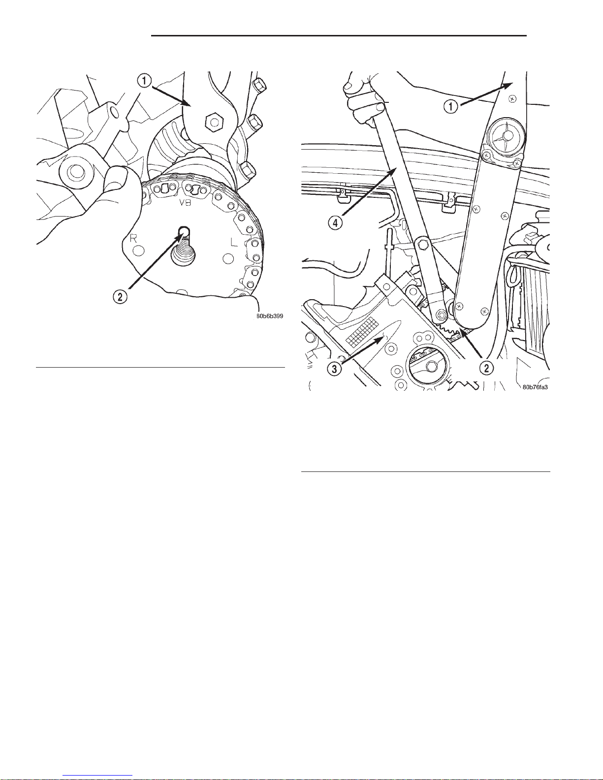
ENGINE TIMING—VERIFICATION
CAUTION: The 4.7L is a non free-wheeling design
engine. Therefore, correct engine timing is critical.
NOTE: Components referred to as left hand or right
hand are as viewed from the drivers position inside
the vehicle.
NOTE: The blue link plates on the chains and the
dots on the camshaft drive sprockets may not line
up during the timing verification procedure. The
blue link plates are lined up with the sprocket dots
only when re-timing the complete timing drive.
Once the timing drive is rotated blue link-to-dot
alignment is no longer valid.
Engine base timing can be verified by the following
procedure:
(1) Remove the cylinder head covers. Refer to the
procedure in this section.
(2) Using a mirror, locate the TDC arrow on the
front cover (Fig. 11). Rotate the crankshaft until the
mark on the crankshaft damper is aligned with the
TDC arrow on the front cover. The engine is now at
TDC.

9 - 20 4.7L ENGINE DN
SERVICE PROCEDURES (Continued)
SINGLE CAMSHAFT TIMING
NOTE: to adjust the timing on one camshaft, preform the following procedure.
(1) Using Chain Tensioner Wedge, special tool
8350, stabilize the secondary chain drive. For reference purposes, mark the chain-to-sprocket position
(Fig. 13).
(2) Remove the camshaft drive gear retaining bolt.
(3) Carefully remove the camshaft drive gear from
the camshaft.
(4) Re-index the camshaft drive gear in the chain
until the V8 mark is at the same position as the V8
mark on the opposite camshaft drive gear.
NOTE: When gripping the camshaft, place the pliers on the tube portion of the camshaft only. Do not
grip the lobes or the sprocket areas.
(5) Using a suitable pair of adjustable pliers,
rotate the camshaft until the alignment dowel on the
Fig. 11 Engine Top Dead Center (TDC) Indicator
Mark
1 – TIMING CHAIN COVER
2 – CRANKSHAFT TIMING MARKS
(3) Note the location of the V8 mark stamped into
the camshaft drive gears (Fig. 12). If the V8 mark on
each camshaft drive gear is at the twelve o’clock position, the engine is at TDC on the exhaust stroke. If
the V8 mark on each gear is at the six o’clock position, the engine is at TDC on the compression stroke.
(4) If both of the camshaft drive gears are off in
the same or opposite directions, the primary chain or
both secondary chains are at fault. Refer to Timing
Chain and Sprockets procedure in this section.
(5) If only one of the camshaft drive gears is off
and the other is correct, the problem is confined to
one secondary chain. Refer to Single camshaft timing, in this procedure.
(6) If both camshaft drive gear V8 marks are at
the twelve o’clock or the six o’ clock position the
engine base timing is correct. Reinstall the cylinder
head covers.
camshaft is aligned with the slot in the camshaft
drive gear (Fig. 14).
CAUTION: Remove excess oil from camshaft
sprocket retaining bolt before reinstalling bolt. Failure to do so may cause over-torqueing of bolt
resulting in bolt failure.
(6) Position the camshaft drive gear onto the camshaft, remove oil from bolt then install the retaining
bolt. Using Special Tools, Spanner Wrench 6958 with
Adapter Pins 8346 and a suitable torque wrench,
Tighten retaining bolt to 122N·m (90 ft. Lbs.) (Fig.
15) (Fig. 16).
(7) Remove special tool 8350.
(8) Rotate the crankshaft two full revolutions, then
reverify that the camshaft drive gear V8 marks are
in fact aligned.
(9) Install the cylinder head covers. Refer to Cylinder Head Cover in this section.

DN 4.7L ENGINE 9 - 21
SERVICE PROCEDURES (Continued)
1 – LEFT CYLINDER HEAD
2 – RIGHT CYLINDER HEAD
Fig. 12 Camshaft Sprocket V8 Marks
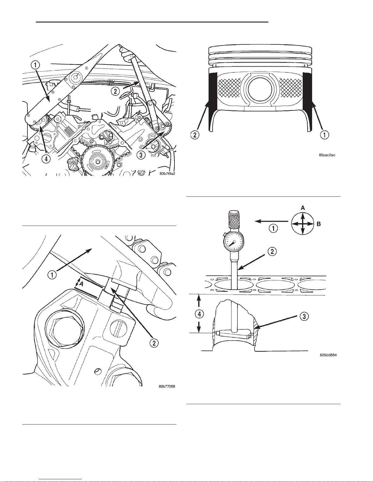
Fig. 13 Securing Timing Chain Tensioners Using Timing Chain Wedge
1 – LEFT CYLINDER HEAD
2 – RIGHT CYLINDER HEAD
3 – SPECIAL TOOL 8350 WEDGE
4 – SPECIAL TOOL 8350 WEDGE
9 - 22 4.7L ENGINE DN
SERVICE PROCEDURES (Continued)
Fig. 14 Camshaft Dowel To Sprocket Alignment
1 – ADJUSTABLE PLIERS
2 – CAMSHAFT DOWEL
TIMING CHAIN—MEASURING WEAR
NOTE: This procedure must be performed with the
timing chain cover removed.
(1) Remove the timing chain cover. Refer to Timing
Chain Cover in this section for procedure.
(2) To determine if the secondary timing chains
are worn, rotate the engine clockwise until maximum
tensioner piston extension is obtained. Measure the
distance between the secondary timing chain tensioner housing and the step ledge on the piston (Fig.
17). The measurement at point (A) must be less than
15mm (.5906 inches).
(3) If the measurement exceeds the specification
the secondary timing chains are worn and require
replacement. Refer to Timing Chain and Sprockets in
this section for procedure.
PISTONS—FITTING
BORE GAGE METHOD
(1) To correctly select the proper size piston, a cylinder bore gauge, capable of reading in 0.003 mm
(.0001 in.) INCREMENTS is required. If a bore
gauge is not available, do not use an inside micrometer.
(2) Measure the inside diameter of the cylinder
bore at a point 49.5 mm (1-15/16 inches) below top of
bore. Start perpendicular (across or at 90 degrees) to
the axis of the crankshaft at point A and then take
Fig. 15 Camshaft Sprocket Installation—Left
Cylinder Head
1 – TORQUE WRENCH
2 – CAMSHAFT SPROCKET
3 – LEFT CYLINDER HEAD
4 – SPECIAL TOOL 6958 SPANNER WITH ADAPTER PINS 8346
an additional bore reading 90 degrees to that at point
B (Fig. 19).
(3) The coated pistons will be serviced with the
piston pin and connecting rod pre-assembled. Tin
coated pistons should not be used as replacements for
coated pistons.
(4) The coating material is applied to the piston
after the final piston machining process. Measuring
the outside diameter of a coated piston will not provide accurate results (Fig. 18). Therefore measuring
the inside diameter of the cylinder bore with a dial
Bore Gauge is MANDATORY. To correctly select the
proper size piston, a cylinder bore gauge capable of
reading in 0.003 mm (.0001 in.) increments is
required.
(5) Piston installation into the cylinder bore
requires slightly more pressure than that required
for non-coated pistons. The bonded coating on the
piston will give the appearance of a line-to-line fit
with the cylinder bore.
DN 4.7L ENGINE 9 - 23
SERVICE PROCEDURES (Continued)
Fig. 18 Moly Coated Piston
Fig. 16 Camshaft Sprocket Installation—Right
Cylinder Head
1 – TORQUE WRENCH
2 – SPECIAL TOOL 6958 WITH ADAPTER PINS 8346
3 – LEFT CAMSHAFT SPROCKET
4 – RIGHT CAMSHAFT SPROCKET
1 – MOLY COATED
2 – MOLY COATED
Fig. 17 Measuring Secondary Timing Chains For
Stretch
1 – SECONDARY TENSIONER ARM
2 – SECONDARY CHAIN TENSIONER PISTON
Fig. 19 Bore Gauge—Typical
1 – FRONT
2 – BORE GAUGE
3 – CYLINDER BORE
4 – 49.5 MM
(1–15/16 in)
9 - 24 4.7L ENGINE DN
2000 DN Service Manual
SERVICE PROCEDURES (Continued)
Publication No. 81-370-0016
TSB 26-12-99 December, 1999
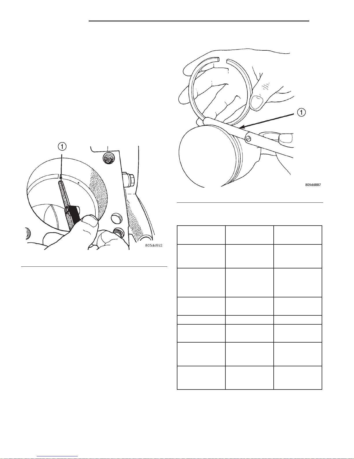
PISTON RINGS—FITTING
RING END GAP
Before reinstalling used rings or installing new
rings, the ring clearances must be checked.
(1) Wipe the cylinder bore clean.
(2) Insert the ring in the cylinder bore.
NOTE: The ring gap measurement must be made
with the ring positioned at least 12mm (0.50 inch.)
from bottom of cylinder bore.
(3) Using a piston, to ensure that the ring is
squared in the cylinder bore, slide the ring downward
into the cylinder.
(4) Using a feeler gauge check the ring end gap
(Fig. 20). Replace any rings not within specification.
Fig. 20 Ring End Gap Measurement—Typical
1 – FEELER GAUGE
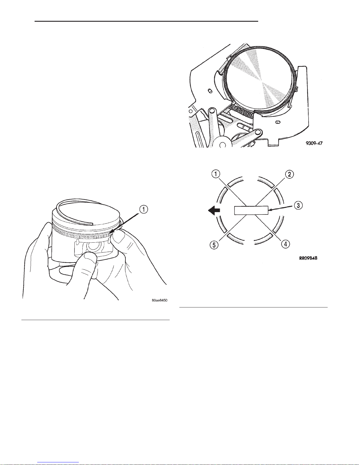
PISTON RING SIDE CLEARANCE
NOTE: Make sure the piston ring grooves are clean
and free of nicks and burrs.
(5) Measure the ring side clearance as shown (Fig.
21) make sure the feeler gauge fits snugly between
the ring land and the ring. Replace any ring not
within specification.
(6) Rotate the ring around the piston, the ring
must rotate in the groove with out binding.
EARLY BUILD
(7) The No. 1 and No. 2 piston rings have a different cross section. Ensure No. 2 ring is installed with
manufacturers I.D. mark (Dot) facing up, towards top
of the piston.
LATE BUILD
The No. 1 and No. 2 piston rings have a different
cross section. Ensure No. 2 ring is installed with
manufacturers I.D. mark (Dot) facing up, towards top
of the piston. On late build engines the piston top
ring groove and crown are not anodized therefore,
the No. 1 piston ring is coated with an anti-friction
coating. Care must be used to ensure that when
Fig. 21 Measuring Piston Ring Side Clearance
1 – FEELER GAUGE
PISTON RING SPECIFICATION CHART
Ring Position Groove Maximum
Clearance Clearance
Upper Ring .051-.094mm 0.11mm
(0.0020-.0037
in.)
Intermediate
Ring
Oil Control Ring .019-.229mm .25mm
(Steel Rails) (.0007-.0090 in.) (0.010 in.)
Ring Position Ring Gap Wear Limit
Upper Ring 0.20-0.36mm 0.40mm
Intermediate
Ring
Oil Control Ring 0.025-0.76mm 1.52mm
(Steel Rail) (0.010- 0.030
0.04-0.08mm 0.10mm
(0.0016-0.0031
in.)
(0.008-0.014 in.) (0.0016in.)
0.37-0.63mm 0.71mm
(0.014-0.025 in.) (0.028in.)
in.)
(0.004 in.)
(0.004 in.)
(0.060in.)
installing piston rings on late build engines that the
correct No. 1 piston ring be installed, failure to use
the correct piston ring can cause severe damage to
the piston and/or cylinder block.
DN 4.7L ENGINE 9 - 25
SERVICE PROCEDURES (Continued)
NOTE: Piston rings are installed in the following
order:
• Oil ring expander.
• Upper oil ring side rail.
• Lower oil ring side rail.
• No. 2 Intermediate piston ring.
• No. 1 Upper piston ring.
(8) Install the oil ring expander.
(9) Install upper side rail (Fig. 22) by placing one
end between the piston ring groove and the expander
ring. Hold end firmly and press down the portion to
be installed until side rail is in position. Repeat this
step for the lower side rail.
(10) Install No. 2 intermediate piston ring using a
piston ring installer (Fig. 23).
(11) Install No. 1 upper piston ring using a piston
ring installer (Fig. 23).
(12) Position piston ring end gaps as shown in
(Fig. 24). It is important that expander ring gap is at
least 45° from the side rail gaps, but not on the piston pin center or on the thrust direction.
Fig. 23 Upper and Intermediate Rings—Installation
Fig. 22 Side Rail—Installation
1 – SIDE RAIL END
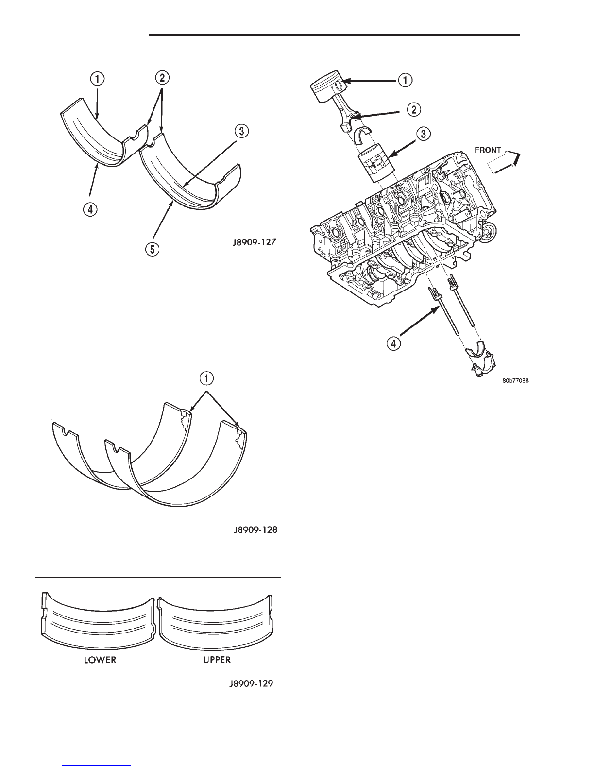
CONNECTING ROD BEARINGS—FITTING
Inspect the connecting rod bearings for scoring and
bent alignment tabs (Fig. 25) (Fig. 26). Check the
bearings for normal wear patterns, scoring, grooving,
fatigue and pitting (Fig. 27). Replace any bearing
that shows abnormal wear.
Inspect the connecting rod journals for signs of
scoring, nicks and burrs.
Misaligned or bent connecting rods can cause
abnormal wear on pistons, piston rings, cylinder
walls, connecting rod bearings and crankshaft connecting rod journals. If wear patterns or damage to
any of these components indicate the probability of a
misaligned connecting rod, inspect it for correct rod
Fig. 24 Piston Ring End Gap Position
1 – SIDE RAIL UPPER
2 – NO. 1 RING GAP
3 – PISTON PIN
4 – SIDE RAIL LOWER
5 – NO. 2 RING GAP AND SPACER EXPANDER GAP
alignment. Replace misaligned, bent or twisted connecting rods.
(1) Wipe the oil from the connecting rod journal.
(2) Lubricate the upper bearing insert and install
in connecting rod.
(3) Use piston ring compressor and Guide Pins
Special Tool 8507 (Fig. 28) to install the rod and piston assemblies. The oil slinger slots in the rods must
face front of the engine. The “F”’s near the piston
wrist pin bore should point to the front of the engine.
(4) Install the lower bearing insert in the bearing
cap. The lower insert must be dry. Place strip of Plastigage across full width of the lower insert at the center of bearing cap. Plastigage must not crumble in
use. If brittle, obtain fresh stock.
9 - 26 4.7L ENGINE DN
SERVICE PROCEDURES (Continued)
Fig. 25 Connecting Rod Bearing Inspection
1 – UPPER BEARING HALF
2 – MATING EDGES
3 – GROOVES CAUSED BY ROD BOLTS SCRATCHING
JOURNAL DURING INSTALLATION
4 – WEAR PATTERN — ALWAYS GREATER ON UPPER
BEARING
5 – LOWER BEARING HALF
Fig. 26 Locking Tab Inspection
1 – ABNORMAL CONTACT AREA CAUSED BY LOCKING TABS
NOT FULLY SEATED OR BEING BENT
Fig. 27 Scoring Caused by Insufficient Lubrication
or by Damaged Crankshaft Pin Journal
Fig. 28 Piston and Connecting Rod—Installation
1 – “F” TOWARD FRONT OF ENGINE
2 – OIL SLINGER SLOT
3 – RING COMPRESSOR
4 – SPECIAL TOOL 8507
(5) Install bearing cap and connecting rod on the
journal and tighten bolts to 27 N·m (20 ft. lbs.) plus a
90° turn. DO NOT rotate crankshaft. Plastigage will
smear, resulting in inaccurate indication.
(6) Remove the bearing cap and determine amount
of bearing-to-journal clearance by measuring the
width of compressed Plastigage (Fig. 29). Refer to
Engine Specifications for the proper clearance. Plas-
tigage should indicate the same clearance
across the entire width of the insert. If the
clearance varies, it may be caused by either a
tapered journal, bent connecting rod or foreign
material trapped between the insert and cap or
rod.
(7) If the correct clearance is indicated, replacement of the bearing inserts is not necessary. Remove
the Plastigage from crankshaft journal and bearing
insert. Proceed with installation.
(8) If bearing-to-journal clearance exceeds the
specification, determin which services bearing set to
use the bearing sizes are as follows:

DN 4.7L ENGINE 9 - 27
SERVICE PROCEDURES (Continued)
Fig. 29 Measuring Bearing Clearance with
Plastigage
1 – PLASTIGAGE SCALE
2 – COMPRESSED PLASTIGAGE
Bearing
SIZE USED WITH
Mark
JOURNAL SIZE
.025 US .025 mm 50.983-50.967 mm
(.001 in.) (2.0073-2.0066 in.)
Std. STANDARD 50.992-51.008 mm
(2.0076-2.0082 in.)
.250 US .250 mm 50.758-50.742 mm
(.010 in.) (1.9984-1.9978 in.)
(9) Repeat the Plastigage measurement to verify
your bearing selection prior to final assembly.
(10) Once you have selected the proper insert,
install the insert and cap. Tighten the connecting rod
bolts to 27 N·m (20 ft. lbs.) plus a 90° turn.
Slide snug-fitting feeler gauge between the connecting rod and crankshaft journal flange (Fig. 30).
Refer to Engine Specifications for the proper clearance. Replace the connecting rod if the side clearance
is not within specification.
CRANKSHAFT MAIN BEARINGS
INSPECTION
Wipe the inserts clean and inspect for abnormal
wear patterns and for metal or other foreign material
imbedded in the lining. Normal main bearing insert
wear patterns are illustrated (Fig. 31).
NOTE: If any of the crankshaft journals are scored,
remove the engine for crankshaft repair.
Fig. 30 Checking Connecting Rod Side Clearance—
Typical
Fig. 31 Main Bearing Wear Patterns
1 – UPPER INSERT
2 – NO WEAR IN THIS AREA
3 – LOW AREA IN BEARING LINING
4 – LOWER INSERT
Inspect the back of the inserts for fractures, scrap-
ings or irregular wear patterns.
Inspect the upper insert locking tabs for damage.
Replace all damaged or worn bearing inserts.
MAIN BEARING JOURNAL DIAMETER
(CRANKSHAFT REMOVED)
Remove the crankshaft from the cylinder block.
Refer to Crankshaft in this section for procedure.
Clean the oil off the main bearing journal.
Determine the maximum diameter of the journal
with a micrometer. Measure at two locations 90°
apart at each end of the journal.
The maximum allowable taper is 0.008mm (0.0004
inch.) and maximum out of round is 0.005mm (0.002
inch). Compare the measured diameter with the jour-
9 - 28 4.7L ENGINE DN
SERVICE PROCEDURES (Continued)
nal diameter specification (Main Bearing Fitting
Chart). Select inserts required to obtain the specified
bearing-to-journal clearance.
Install the crankshaft into the cylinder block. Refer
to Crankshaft in this section for procedure.
CRANKSHAFT MAIN BEARING SELECTION
(1) Service main bearings are available in three
grades. The chart below identifies the three service
grades available.
GRADE SIZE mm
(in.)
MARKING JOURNAL SIZE
A .008 mm U/S 63.488-63.496 mm
(.0004 in.)
U/S
B STANDARD 63.496-63.504 mm
C .008 mm O/S 63.504-63.512 mm
(.0004 in.)
O/S
FOR USE WITH
(2.4996-2.4999 in.)
(2.4996-2.4999 in.)
(2.5002-2.5005 in.)
REMOVAL AND INSTALLATION
ENGINE MOUNTS—LEFT AND RIGHT
REMOVAL
(1) Disconnect the negative cable from the battery.
CAUTION: Remove the fan blade, fan clutch and
fan shroud before raising engine. Failure to do so
may cause damage to the fan blade, fan clutch and
fan shroud.
(2) Remove the fan blade, fan clutch and fan
shroud. Refer to Group 7. for procedure.
(3) Remove the engine oil filter.
(4) Support the engine with a suitable jack and a
block of wood across the full width of the engine oil
pan.
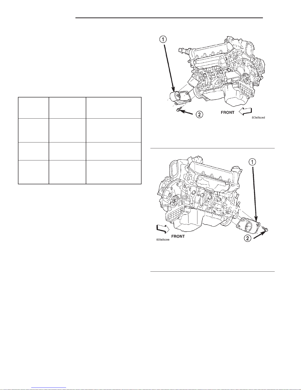
(5) Remove the four (4) cylinder block-to-insulator
mount bolts and the nut from the engine insulator
mount through bolt (4x2 Vehicles only) (Fig. 32) (Fig.
33).
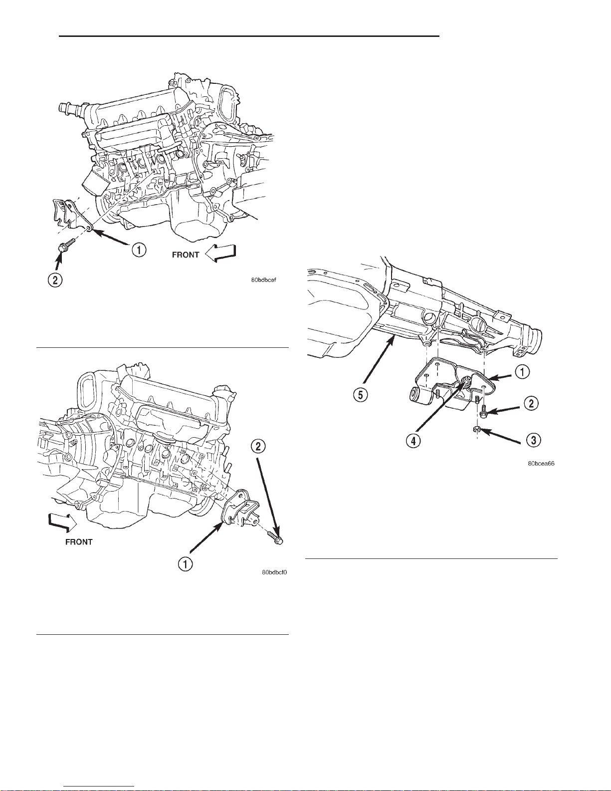
(6) Remove the three (3) cylinder block-to-insulator
mount bolts and loosen the nut from the engine insulator mount through bolt (4x4 Vehicles only) (Fig. 34)
(Fig. 35).
(7) Using the jack, raise the engine high enough to
remove the engine insulator mount through bolt and
the insulator mount.
Fig. 32 Engine Insulator Mount 4x2 Vehicle—Left
Side
1 – ENGINE INSULATOR MOUNT-LEFT SIDE
2 – MOUNTING BOLT
Fig. 33 Engine Insulator Mount 4x2 Vehicle—Right
Side
1 – ENGINE INSULATOR MOUNT-RIGHT SIDE
2 – MOUNTING BOLT
INSTALLATION
(1) Position the insulator mount and install the
insulator mount through bolt.
(2) Lower the engine until the four cylinder block-
to-insulator mount bolts can be installed.
(3) Remove the jack and block of wood.
(4) Torque the cylinder block-to-insulator mount
bolts to 61N·m ( 45 ft. lbs.).
(5) Install and torque the through bolt retaining
nut to 61N·m (45 ft. lbs.).
(6) Install the fan blade, fan clutch and fan
shroud.
DN 4.7L ENGINE 9 - 29
REMOVAL AND INSTALLATION (Continued)
(4) Remove the four bolts and washers retaining
the mount to the transmission (4x4 automatic transmission only) (Fig. 38).
(5) Raise the transmission enough to remove the
through bolt (Manual transmission and 4x2 automatic transmission only) (Fig. 36) (Fig. 37).
(6) Raise the transmission and remove the bolts
retaining the mount to the crossmember (4x4 automatic transmission only) (Fig. 38).
(7) Remove the two nuts retaining the isolator to
the crossmember (Manual transmission and 4x2
automatic transmission only) (Fig. 36) (Fig. 37).
(8) Remove the bolts (two bolts manual transmission)(three bolts 4x2 automatic transmission) retaining the insulator bracket to the transmission.
Fig. 34 Engine Insulator Mount 4x4 Vehicle—Left
Side
1 – ENGINE INSULATOR MOUNT-LEFT SIDE
2 – MOUNTING BOLT
Fig. 35 Engine Insulator Mount 4x4 Vehicle—Right
Side
1 – ENGINE INSULATOR MOUNT-RIGHT SIDE
2 – MOUNTING BOLT
ENGINE MOUNT—REAR
REMOVAL
(1) Raise vehicle on hoist.
(2) Using a suitable jack, support transmission.
(3) Remove the nut from the insulator mount
through bolt (Manual transmission and 4x2 automatic transmission only) (Fig. 36) (Fig. 37).
Fig. 36 Engine Rear Mount—4X2 Automatic
Transmission
1 – ENGINE REAR MOUNT
2 – BOLT
3 – NUT
4 – THROUGH BOLT NUT
5 – TRANSMISSION
INSTALLATION
(1) Follow the removal procedure in the reverse
order.
(2) Tighten the through bolt retaining nut to 102
N·m (75 ft. lbs.).
(3) Tighten the isolator bracket to transmission
retaining bolts (Manual transmission and 4x2 automatic transmission only) to 41 N·m (30 ft. lbs.).
(4) Tighten the mount bracket to transmission
retaining bolts (4x4 automatic transmission only) to
68 N·m (50 ft. lbs.).
(5) Tighten the isolator mount to crossmember
retaining nuts (Manual transmission and 4x2 automatic transmission only) to 28 N·m (250 in. lbs.).
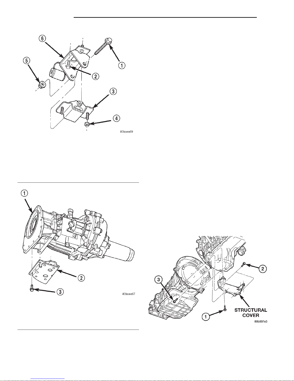
9 - 30 4.7L ENGINE DN
REMOVAL AND INSTALLATION (Continued)
STRUCTURAL COVER
REMOVAL
(1) Raise vehicle on hoist.
(2) Remove the left hand exhaust pipe from
exhaust manifold. Refer to Group 11, Exhaust System.
(3) Loosen the right hand exhaust manifold-to-exhaust pipe retaining bolts.
(4) Remove the eight bolts retaining structural
cover (Fig. 39).
(5) Pivot the exhaust pipe downward and remove
the structural cover.
INSTALLATION
CAUTION: The structural cover must be installed
as described in the following steps. Failure to do so
Fig. 37 Engine Rear Mount—4X2 and 4X4 Manual
Transmission
1 – THROUGH BOLT
2 – BOLT
3 – INSULATOR SUPPORT
4 – NUT
5 – NUTAND WASHER
6 – INSULATOR BRACKET TO TRANSMISSION
will cause severe damage to the cover.
(1) Position the structural cover in the vehicle.
(2) Install all four bolts retaining the cover-to-engine. DO NOT tighten the bolts at this time.
(3) Install the four cover-to-transmission bolts. Do
NOT tighten at this time.
CAUTION: The structural cover must be held tightly
against both the engine and the transmission bell
housing during tightening sequence. Failure to do
so may cause damage to the cover.
Fig. 38 Engine Rear Mount—4X4 Automatic
Transmission
1 – TRANSMISSION
2 – ENGINE REAR MOUNT
3 – BOLT
(6) Tighten the mount bracket to crossmember
retaining bolts (4x4 automatic transmission only) to
28 N·m (250 in. lbs.).
(4) Starting with the two rear cover-to-engine
bolts, tighten bolts (1) (Fig. 39) to 54 N·m (40 ft. lbs.),
then tighten bolts (2) (Fig. 39) and (3) to 54 N·m ( 40
ft. lbs.) in the sequence shown.
Fig. 39 Structural Cover
(5) Install the exhaust pipe on left hand exhaust
manifold.
(6) Tighten exhaust manifold-to-exhaust pipe
retaining bolts to 20–26 N·m (15–20 ft. lbs.).
 Loading...