

Page 1

Introduction
Congratulations, and thank you for your purchase of
the DOD direct box. The AC 260,265,275, and 285 all
solve distortion problems normally associated with
using high impedance sources with low impedance
inputs. The product line begins with the AC 260 which
is a basic easy to use direct box and progresses into
the AC 285 with a cabinet emulator. The features,
operation, and specifications literature have been individualized for each box. Determine which box you
have and consult the following text until you reach the
section that is specific to your box.
AC 260 Direct Box
Features of the AC 260
• Allows a hi impedance unbalanced source to directly
feed a low impedance balanced input.
• Low distortion
• Low noise
• Rugged metal chassis
Operation of the AC 260
• Connect the output of the high impedance source to
the input of the AC260.
• Connect the low impedance output of the AC260 to a
mixing console or other low impedance input.
Connect the unbalanced 1/4” tip-sleeve output to a
high impedance input.
Page 2

XLR
12
3
600Ω CT 50KΩ
1/4"
Hi Z
Block Diagram AC260
Specifications of the AC 260
Low Impedance In/Output: 600 ohms center tapped
(balanced).
Low Impedance Connector: XLR type jack.
High Impedance In/Outputs: 50KΩ.
High Impedance Connectors: 2- 1/4” mono phone
jacks
AC 265 Direct Box
Features of the AC 265
• Connects high impedance (50K ohms) to low impedance (600 ohms), or low impedance to high imped-
ance.
• Ground lift switch to fix ground-loop hum problems.
• Allows a hi impedance unbalanced source to directly
feed a low impedance balanced input.
• Low distortion
• Low noise
• Adjustable attenuation pad, makes this different from
the AC 260.
Operation of the AC 265
• Connect the output of the high impedance source to
the input of the AC 265.
• Connect the low impedance output of the AC 265 to a
Page 3
mixing console or other low impedance input.
Connect the unbalanced 1/4” tip-sleeve output to a
high impedance input (if desired) .
• Set the ground lift switch to the position with the least
amount of hum or noise.
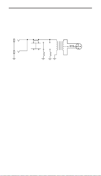
47K
50K
4.7K
470Ω
WHT GRN
BLUORG
XLR
GND LIFT
YEL
Block Diagram AC265
Specifications of the AC 265
Low Impedance In/Output: 600 ohms center tapped
(balanced).
Low Impedance Connector: XLR type jack
High Impedance In/Outputs: 50K ohms (unbalanced)
High Impedance Connectors: 2 -1/4 inch mono phone
jacks.
Attenuation Range Switch: 0,12,40 dB attenuation
Frequency Response: 60 to 15 kHz, ±3 dB
AC 275 Active Direct Box
Features of the AC 275
• Allows a hi impedance unbalanced source to directly
feed a low impedance balanced input.
• Connects guitar pickups, microphones or electric
instruments to a recording or P.A. console without
audio quality loss.
• Input signal isolation using FET input operational
amplifiers that reduce loading effects normally found
600Ω
Page 4

on passive direct boxes.
• Flat frequency response.
• Operates with battery or phantom power.
• Ground isolation switch.
• Internal pad for speaker level input.
Operation of the AC 275
• Connect the output of the high impedance source to
the input of the AC275.
• Connect the low impedance output of the AC275 to a
mixing console or other low impedance input.
Connect the unbalanced 1/4” tip-sleeve output to a
high impedance input (if desired). This output is
hard-wired to the input.
• Set the ground lift switch to the position with the least
amount of hum or noise.
• Set pad switch to INSTRUMENT for line level input
sources or to SPEAKER for speaker level input
sources. Set power selector switch to ON for battery
power or to OFF for phantom power.
NOTE: To preserve battery life, set power selector switch
to OFF when AC275 is not in use.
Unbalanced
Hi-Z Input
-12dB (INST)
-40dB (SPKR)
PAD
Battery
Phantom Power
+
Unbalanced
Output
Left
Ground
Block Diagram AC275
Specifications of the AC 275
Balanced
+
-
Low-Z
Output
1
3
2
Page 5

Frequency Response: 20Hz-20kHz, ±0.5dB
Page 6

Gain:
Inst: -12dBu
Spkr: -40dBu
Input Impedance: Instrument 1.3MΩ
Output Impedance: 200Ω
Power Requirements: 9V battery or 15-48V phan-
Distortion(1kHz, Inst @-10dBV input): <0.02%
Signal-to-Noise Ratio (Inst @-10dBV input):
Maximum Input:
Instrument Position: +7dBu (9V battery)
Supply Current: 4mA (9V battery)
Input Connector: 1/4” tip-sleeve
Output Connector: XLR, 1/4” tip-sleeve
Dimensions: 2.5”x4.5”x1.5”
Weight: 15oz (422g)
Note: 0dBV=1.0 Vrms; 0dBu=0.775 Vrms
Speaker 10kΩ
tom power
Better than 86dB
+5dBu (15V phantom)
+20dBu (48V phantom)
4mA (15V phantom)
8mA (48V phantom)
AC 285
Features of the AC 285
• Allows a hi impedance unbalanced source to directly
feed a low impedance balanced input.
• Connects guitar pickups, microphones, or electric
instruments to a recording or P.A. console without
audio quality loss.
• Input signal isolation using FET input operational
Page 7

amplifiers that reduce loading effects.
• Flat frequency response.
• Operates with battery or phantom power.
• Ground isolation switch.
• Internal pad for speaker level input.
• 4x12 emulator cabinet that gives a more enhanced
low end.
• Twin open-back combo that provides a brighter
sound with less low end.
Operation of the AC 285
• Connect the output of the high impedance source to
the input of the AC 285.
• Connect the low impedance output of the AC 285 to a
mixing console or other low impedance input.
Connect the unbalanced 1/4” tip-sleeve output to a
high impedance input (if desired).
• Set the ground lift switch to the position with the least
amount of hum or noise.
• Set pad switch to INSTRUMENT for line level input
sources or to SPEAKER for speaker level input
sources. Set power selector switch to ON for battery
power or to OFF for phantom power.
• Set speaker settings to FLAT if you want the directto-microphone sound. If you are seeking the guitarto-board sound, the 4x12 or COMBO settings are
great.
Page 8

Unbalanced
Hi-Z Input
Unbalanced
Output
Left
Ground
-12dB (INST)
-40dB (SPKR)
FLAT 4x12
COMBO
PAD
Phantom Power
Battery
+
Balanced
+
-
Low-Z
Output
123
Specifications of the AC 285
Block Diagram AC285
Frequency Response: 20-18 kHz ±1dB
10-30 kHz ±3dB
Gain:
Instr: -12dB
Spkr: -40dB
Input Impedance:
Inst: > 1 megΩ
Spkr: >200 kΩ
Output Impedance: 200Ω
Power Requirements:
9V Battery
15-48V Phantom
9V AC Adapter
(DOD PS3)
THD (1kHz, Inst @ 0dBu, 9V batt):
<0.08%
Signal to Noise Ratio (Inst @ -10dBu, 9V):
Flat: >86dB
Spkr Emulation: >80dB
Maximum Input Level (Inst):
7dBu (9V battery or adapter)
5dBu (15V Phantom)
20dBu (48V Phantom)
Supply Current: 8 mA (9V battery)
Page 9

16 mA (48V Phantom)
DOD Electronics Corporation
8760 South Sandy Parkway
Sandy, Utah 84070
Telephone (801) 566-8800
FAX (801) 566-7005
International Distribution
3 Overland Drive, Unit 4
Amherst, New Hampshire 03031
U.S.A.
FAX (603) 672-4246
Copyright © 1994 DOD Electronics Corporation
Printed in U.S.A. 12/94
Manufactured in the U.S.A.
AC260,270,275,&285 18-0054-B
Page 10

AC
260
265
275
285
Instruction Manual
 Loading...