

Page 1

L-01G
INSTRUCTION MANUAL
’15.2
Page 2
Introduction
Thank you for purchasing L-01G.
Before or while using, read this manual thoroughly to ensure you use correctly.
L-01G Usage Manuals
■ "L-01G Setting Up Manual" (Japanese) (Supplied accessory)
It describes how to connect this terminal with PC, etc.
■ "Notes on Usage" (Supplied accessory)
Precautions on using this terminal are described. Be sure to read it before using.
■ "L-01G INSTRUCTION MANUAL" (PDF le)
Details about functions and operations are explained.
Download from DOCOMO website.
http://www.nttdocomo.co.jp/english/support/trouble/manual/download/index.html
* The URL, as well as the contents are subject to change without prior notice.
How to Read this Manual
In this manual, the operations are described by illustrations and marks to ensure the correct usage of this
terminal.
• Please note that "this terminal" indicates "L-01G" in this manual.
• Images and illustrations used in this manual may dier from the real images displayed on this terminal
or dier from the real product.
• Please note that "PC" indicates both "Windows" and "Mac" in this manual.
• Any reprint of this manual is prohibited.
• This manual is subject to change without prior notice.
Page 3
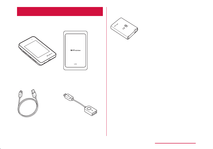
Supplied Accessories
■ L-01G
Terminal
(with warranty)
■ Back cover L39
■ Battery Pack L23 ■ Notes on Usage
(Japanese)
■ L-01G Setting
Up Manual
(Japanese)
■ SSID/Security
sticker
For options (sold separately) compatible with
this terminal, visit DOCOMO website.
https://www.nttdocomo.co.jp/product/option/
(in Japanese only)
■ USB Cable L03
■ Converter Cable
for Charging L02
Contents/Precautions
1
Page 4

Contents
Supplied Accessories ………………………………… 1
About Usage of this Terminal ……………………… 4
Main Functions …………………………………………… 5
Safety Precautions (ALWAYS FOLLOW THESE
PRECAUTIONS) ………………………………………………… 8
Handling and Care …………………………………… 23
Before Using this Terminal …………… 30
Part Names and Functions ………………………… 30
Using docomo mini UIM card ……………………… 32
Attaching/Removing Battery Pack ……………… 35
Charging ………………………………………………… 38
Power On/O …………………………………………… 40
Viewing Display ……………………………………… 41
Basic Operations ……………………………………… 44
Entering a Character ………………………………… 46
Setting up ………………………………… 47
Setup …………………………………………………… 47
Setup Flow ……………………………………………… 50
For Wireless Connection …………………………… 51
For USB Connection ………………………………… 63
Setting Each Item …………………………………… 71
Contents/Precautions
2
Settings (Web browser) ……………… 72
Logging in to the Setting Page
(L-01G Connection Manager) …………………… 72
Conrming Connection State or Setting
State of this Terminal ……………………………… 76
Setting Provider ……………………………………… 77
Setting Public Wireless LAN ……………………… 78
Setting Network ……………………………………… 80
Advanced Settings of Wireless LAN …………… 82
Setting Router ………………………………………… 91
Managing System …………………………………… 96
Settings (setting menu on this terminal)
………………………………………………… 101
Setting on the Display of this Terminal
(Setting Menu) …………………………………………101
Overseas Use …………………………… 112
Overview of International Roaming
(WORLD WING) …………………………………………112
Available Services ……………………………………112
Conrming before Using …………………………… 113
Charging Mobile Devices …………… 117
Charging Mobile Devices …………………………… 117
Page 5

Appendix/Troubleshooting …………… 119
L-01G Connection Manager Menu Item/Setting
Item List ………………………………………………… 119
Setting Menu Item/Setting Item List …………… 127
Troubleshooting ………………………………………131
Error message …………………………………………138
Warranty and After-Sales Service ………………141
Updating Software ……………………………………144
Resetting this Terminal ……………………………147
Main Specications …………………………………147
Export Administration Regulations ………………150
Specic Absorption Rate (SAR) of Mobile
Terminals ……………………………………………… 151
Declaration of Conformity …………………………152
Important Safety Information ……………………… 154
Intellectual Property Right …………………………157
Unlocking SIM …………………………………………158
Index ………………………………………………………159
Contents/Precautions
3
Page 6

About Usage of this Terminal
• This terminal supports LTE, W-CDMA, GSM/
GPRS and wireless LAN systems.
• Since this terminal uses wireless signal, it may
not be able to use in a location with no signal
reception such as a tunnel, underground, a
building, an outdoor location with weak or poor
signal reception, or a location outside of the Xi
and FOMA service areas. Also this terminal may
not be able to use on high upper oors of highrise apartments or buildings, even if you can see
no obstructions around you. Please note that
on occasion, data communication may become
disconnected even when you are in a strongsignal area with 4 signal bars displayed while
you are not moving.
• Note that we do not take responsibilities for any
pure economic losses caused by communication
problems due to false operations of this terminal,
or in case of power outage, etc.
• This terminal responds to FOMA Plus-Areas and
FOMA HIGH-SPEED Areas.
• You can update the software of this terminal.
(→P144)
• This terminal uses only docomo mini UIM card.
Bring your docomo nano UIM/UIM/FOMA card to
a docomo Shop to exchange it.
Contents/Precautions
4
• Set PIN1 lock for this terminal to ensure the
security in case of the loss. (→P96)
• For the details of usage fee, view, please visit
DOCOMO website.
• Note that we do not guarantee any
performances of the optional accessories you
purchase at stores.
• Communication fee may become high when
browsing websites containing a large amount
of images, downloading a large capacity or
performing a large data communication.
• Depending on the network congestion situation,
communication speed may slow down, or it may
be dicult to connect network.
• This terminal does not support voice call and digital
communication (TV call, 64 K data communication).
• This terminal does not support Remote Wakeup.
• For Internet access on a PC, etc., usage fee of
docomo Xi/FOMA service contract line, together
with usage fee of Internet service provider
such as a corresponding provider "mopera U"
of docomo are charged. For information about
application of "mopera U", service contents and
setting method, view homepage of "mopera U"
(http://www.mopera.net (in Japanese only)).
You can use Internet service provider of other
companies. In that case, pay usage fee directly
to the provider you use. Consult a provider
directly about the detailed information.
Page 7
• Depending on the connection destination, user
authentication (ID and password) may require
while attempting access. In that case, enter ID
and password and connect.
• ID and password are granted by either Internet
service provider or the network administrator of
that access point. Consult directly for detailed
information.
• Even though the display on this terminal applies
advanced technique, part of the dots may not
light up as well as those always-on light. Please
note that this is a feature of the display. It is not
a malfunction.
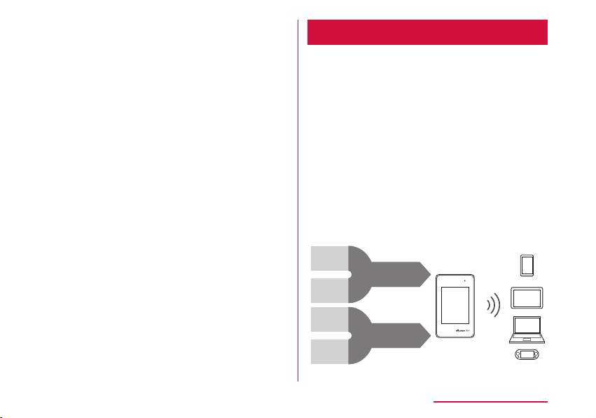
Main Functions
This terminal can be connected to more than
one wireless LAN terminal via wireless LAN
such as a PC or a game machine, and it can
also be connected to a PC, etc. via USB Cable.
In addition, you can access to the Internet
from the connected device using Xi data
communication or FOMA data communication
via this terminal.
This terminal supports LTE-Advanced. Speed
of data communication can reach to maximum
225 Mbps
* Only a part of Xi areas.
Max. 150 Mbps
for receiving
[1.7 GHz]
Max. 75 Mbps
for receiving
[800 MHz]
Max. 112.5 Mbps
for receiving
[1.5 GHz]
Max. 112.5 Mbps
for receiving
[2.0 GHz]
*
for receiving data.
Max. 225 Mbps
for receiving
Max. 225 Mbps
for receiving
Communication speed is an example of configured
frequency patterns and the maximum for receiving.
Max.
225 Mbps
for receiving
Contents/Precautions
5
Page 8

Wireless LAN
Up to 10 devices compatible with wireless
LAN (IEEE802.11a/n/ac (5GHz band),
IEEE802.11b/g/n (2.4GHz band)), such as a
PC or a game machine can be connected to
this terminal.
• This terminal supports WPS function. If the WiFi compatible device you use supports WPS
function, you can set up Wi-Fi connection easily
(→P53 "Connecting to Wi-Fi compatible
device supports WPS").
• Use L-01G Connection Manager to restrict
the number of devices available to connect.
(→P84)
• Even when this terminal is connected to
public wireless LAN, up to 10 devices can be
connected.
Contents/Precautions
6
■ DFS Function
The terminal incorporates a (Radio Law)
compulsory DFS function in order to avoid
interference in the Wi-Fi 5 GHz band. As the
Wi-Fi 5 GHz frequency band used by the
terminal is also used by weather radar and
other facilities, interference with weather
radar may occur depending on where you are
using it.
If the terminal detects radio waves from
weather radar or other source while using
the Wi-Fi 5 GHz band, the DFS function
activates and the terminal automatically
changes to another channel in the Wi-Fi 5
GHz band where there is no interference.
Interference may be unavoidable if there
are several wireless LAN devices or other
devices nearby using the same Wi-Fi 5 GHz
band. In this instance, communication speed
may become extremely slow.
Page 9

Caution
• When the terminal changes from the WiFi 2.4 GHz band to the Wi-Fi 5 GHz band,
it checks for a minimum of 60 seconds
whether there is weather radar or other
source of interference nearby, and uses a
channel where there is no interference to
connect to the network. This is referred to as
DFS check in this manual.
DFS check also activates when you turn
on power while set to the Wi-Fi 5 GHz
band or after the terminal recovers from
being disconnected with Wi-Fi auto o or
similar function. During DFS check, Wi-Fi is
temporarily disconnected then reconnected
after about 1 minute
the network during this time.
Any Wi-Fi devices are also disconnected
from the terminal. Operate the devices to
reconnect as required.
When the terminal changes from 5 GHz to
2.4 GHz, DFS check does not activate, and
network connections are maintained.
* It may take longer depending on the DFS
check result.
*
. You cannot connect to
Xi Data Communication/FOMA
Data Communication
It is charged based on the communication
method of measuring sending and receiving
data amount.
When using an access point compatible to
Xi data communication (LTE) or FOMA data
communication (3G), such as docomo Internet
connection service of mopera U, speed of data
communication can reach to maximum 225
*
for receiving data and maximum 50
Mbps
*
for sending data.
Mbps
* Only a part of Xi areas.
Public wireless LAN
You can use this terminal to access to the
Internet at the station, airport or fast food
restaurants where public wireless LAN service
is available.
Contents/Precautions
7
Page 10
Simple Operations of Touch Panel
DANGER
WARNING
From the simple operations of touch panel, the
basic information is displayed on the display of
this terminal and you can set up the settings
this terminal. (→P101)
Also, you can connect the new Wi-Fi compatible
device by following Wi-Fi connection guide on
the display.
* Only part of the available settings can be
set up by L-01G Connection Manager.
Charging Mobile Device
Connect the supplied USB Cable L03 and
Converter Cable for Charging L02, then
charge the mobile device from this terminal.
(→P117)
Contents/Precautions
8
*
of
Safety Precautions (ALWAYS FOLLOW THESE PRECAUTIONS)
■ Before using this terminal, read these
"Safety Precautions" carefully so that you
can use it properly. After reading the safety
precautions, keep this manual in a safe
place for later reference.
■ These precautions are intended to protect
you and others around you. Read and follow
them carefully to avoid injury, damage to
the product or damage to property.
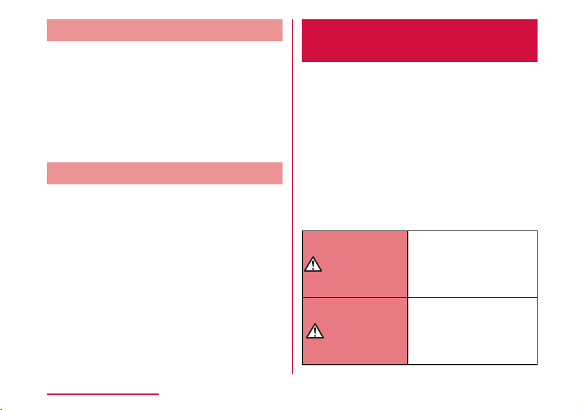
■ The signs below indicate the levels of
danger or damage that may occur if the
particular precautions are not observed.
This sign indicates
that incorrect handling
has a high possibility
of causing death or
serious injury.
This sign indicates
that incorrect
handling poses a risk
of causing death or
serious injury.
Page 11

CAUTION
This sign indicates
that incorrect handling
poses a risk of
causing slight injury
or damage to the
product or property.
■ The following symbols indicate special
warnings regarding product usage.
Denotes things not to do
(prohibition).
Denotes not to disassemble.
Denotes not to use where it
could get wet.
Denotes not to use with wet
hands.
Denotes mandatory
instructions (matters that must
be complied with).
Denotes that the equipment
should be unplugged.
■ "Safety Precautions" are explained in the
following seven sections.
Precautions for This Terminal, Battery Pack,
Adapter, USB Cable, Converter Cable for
Charging, Cradle and docomo mini UIM card
(common) …………………………………………… P10
Precautions for this Terminal ………………… P12
Precautions for Battery Pack …………………P15
Precautions for Adapter, USB Cable, Converter
Cable for Charging and cradle ………………… P17
Precautions for docomo mini UIM card …… P20
Precautions for Using near Electronic Medical
Equipment …………………………………………… P20
Material List …………………………………………P22
Contents/Precautions
9
Page 12
Precautions for This Terminal,
DANGER
WARNING
Battery Pack, Adapter, USB Cable,
Converter Cable for Charging, Cradle
and docomo mini UIM card (common)
Do not use, store or leave it in places
with a high temperature such as
besides re, besides a heater, inside
a kotatsu, under direct sunlight or in
cars under the blazing sun.
Fire, burns, or injury may result.
Do not put in heating appliances
such as microwaves or high pressure
containers.
Fire, burns, injury, or electric shock
may result.
Do not disassemble or remodel.
Fire, burns, injury, or electric shock
may result.
Contents/Precautions
10
Do not get wet with water, drinking
water, pet urine, sweat, etc.
Fire, burns, injury, or electric shock
may result.
Do not get wet on charging terminal
and external connection terminal with
liquids such as water, drinking water,
pet urine, sweat, etc.
Fire, burns, injury, or electric shock
may result.
Use the optional accessories
specied by NTT DOCOMO for this
terminal.
Fire, burns, injury, or electric shock
may result.
Do not put strong force, severe
shocks, or throw them.
Fire, burns, injury, or electric shock
may result.
Page 13
Do not let charging terminal and
CAUTION
external connection terminal touch
any conductive metal such as metal
piece, pencil lead, etc. Also do not
put any of them inside.
Fire, burns, injury, or electric shock
may result.
Do not cover or wrap this terminal
or its accessories with bedding, etc.
while using or charging.
Fire or burns may result.
Make sure to turn o this terminal
or stop charging before going to the
places like a gas station where a
ammable gas fumes.
Catching re may result.
If the equipment starts giving o a
strange smell, overheats, becomes
discolored or deformed during use,
charging or in storage, immediately
perform the following operations.
• Remove the power plug from the wall
outlet or cigar lighter socket.
• Turn o this terminal.
• Remove the battery pack from this
terminal.
Fire, burns, injury, or electric shock
may result.
Do not place the horizontal charge
adapter on unstable locations such
as wobbly tables or slanted locations.
Injury may result from the terminal
falling down.
Do not store the horizontal charge
adapter in humid, dusty places, or in
hot areas.
Fire, burns, or electric shock may
result.
Contents/Precautions
11
Page 14
Contents/Precautions
WARNING
12
If children use a guardian should
explain the precautions and correct
operations. Also make sure that the
instructions are followed during use.
Injury may result.
Keep out of reach of babies and small
children.
Accidental swallowing, injury or
electric shock may result.
Be careful especially when using this
terminal with the adapter connected
continuously for a long time.
This terminal, battery pack, adapter,
USB Cable and Converter Cable for
Charging may become warm when
using for a long time during charging.
Directly touching a hot part for a long
time may cause redness, itching or
rash on your skin, or low-temperature
burns depending on your constitution
and/or health condition.
Precautions for this Terminal
Do not get liquids such as water or
foreign objects such as metal pieces
or ammable materials into the
docomo mini UIM card insertion slot
of this terminal.
Fire, burns, injury, or electric shock
may result.
Turn o the terminal before boarding
an airplane.
The use of mobile phones on
airplanes is restricted. Follow the
instructions of each airline.
Harmful eect on on-board electronic
equipment may result.
Also, you will get punished according
to law if any prohibited action, such
as using the phone in airplane, is
conducted.
Page 15
Follow the instructions when using
this terminal inside medical facilities.
Power o this terminal in places
banning the use of it.
Electronic devices or electronic
medical devices may be adversely
aected.
When you use electronic medical
equipment, check with the equipment
manufacturer to determine how the
device is aected by radio waves
before using.
Harmful eect on electronic medical
equipment etc. may result.
Turn o this terminal in places near
high precision electronic devices
or devices using weak electronic
signals.
Electronic devices may be adversely
aected by reasons such as
malfunction.
* Examples of electronic devices to
avoid
Hearing aids, implanted
cardiac pacemakers, implanted
debrillators, other medical
electronic devices, re alarms,
automatic doors and other
automatically controlled devices.
If you are using an implanted
cardiac pacemaker, implanted
debrillator or any other electronic
medical device, consult the
manufacturer or retailer of the
device for advice regarding possible
eects from radio waves.
Contents/Precautions
13
Page 16

Contents/Precautions
CAUTION
14
When the display is accidentally
broken, be careful of broken glass
or exposed internal parts of this
terminal.
Since the plastic panel is used on
the surface of the display, they are
structured to prevent the glass from
scattering. However, if you carelessly
touch the broken or exposed parts,
you may get injured.
Do not use a broken terminal.
Fire, burns, injury, or electric shock
may result.
If the display part is accidentally
broken and liquid crystal leaks out,
do not make the material contact
with your skin of face or hands.
It leads to blindness or skin problems.
If liquid crystal gets into your eyes or
mouth, rinse it with clean water and
see a doctor immediately.
And, if the material adheres to skin
or clothing, use alcohol etc. to wipe it
o, and then wash with soap.
If you use this terminal in a car,
contact the car manufacturer or
dealer to ask about the eect from
radio waves.
Depending on the type of car, in-car
electronic devices could be adversely
aected. In this case, stop using this
terminal immediately.
Page 17
Itching, rash or eczema may be
DANGER
caused depending on your physical
conditions or predisposition. If an
abnormality occurs, stop using this
terminal immediately, and then seek
medical attention.
• For the material of each part
(→P22 "Material List")
When watching the display, take a
certain distance from the display in a
fully bright place.
Visual loss may result.
Precautions for Battery Pack
■ Conrm the battery type from the label of
the battery pack.
Display Battery type
Li-ion00 Lithium-ion battery
Do not contact the connector with
metal such as wire. Also do not carry
or store it with metal necklace, etc.
Fire, explosion, getting heated or
liquid leak of the battery pack may
result.
Check the orientation of the battery
pack when inserting it into this
terminal. Stop putting excessive
force when any problem is found
during inserting.
Fire, explosion, getting heated or
liquid leak of the battery pack may
result.
Contents/Precautions
15
Page 18
Do not throw this terminal into re.
WARNING
CAUTION
Fire, explosion, getting heated or
liquid leak of the battery pack may
result.
When battery pack leaks liquid or
gives o odor, stop using it and keep
it away from re.
Fire, explosion may result from liquid.
Contents/Precautions
16
Do not sting this terminal with a nail,
and do not hammer or step upon this
terminal.
Fire, explosion, getting heated or
liquid leak of the battery pack may
result.
When the liquid from battery pack
splashes into your eyes, do not rub
your eyes. Wash your eyes and go to
consult with a doctor immediately.
Blindness may result.
Stop using when transformation or
damage is found caused by dropping.
Fire, explosion, getting heated or
liquid leak of the battery pack may
result.
Keep pets away from biting the
battery pack.
Fire, explosion, getting heated or
liquid leak of the battery pack may
result.
Do not discard it as combustible
waste.
Fire and environmental pollution
may result. Tape the connector to
isolate the battery pack and bring it
to a docomo Shop or follow the local
disposal regulations.
Do not use or charge the wet battery
pack.
Fire, explosion, getting heated or
liquid leak of the battery pack may
result.
Page 19
When battery pack leaks liquid inside,
WARNING
do not touch your skin, such as your
face or hands.
It leads to blindness or skin problems.
If such liquid gets into your eyes
or mouth, if it adheres to your skin
or clothing, please rinse with clean
water immediately. If it gets into your
eyes or mouth, please seek medical
attention immediately after washing.
Precautions for Adapter, USB
Cable, Converter Cable for
Charging and cradle
If the adapter code (USB Cable/
Converter Cable for Charging
included) is damaged, do not use any
more.
Fire, burns, or electric shock may
result.
Do not use AC adapter, USB Cable
or Converter Cable for Charging in a
humid place, such as a bathroom.
Fire, burns, or electric shock may
result.
DC adapter is only for minus earth
car. Do not use it on plus earth car.
Fire, burns, or electric shock may
result.
Contents/Precautions
17
Page 20
Do not touch the adapter, USB Cable
or Converter Cable for Charging
during thunder.
Electric shock may result.
Do not make the charging terminal
short out while being connected to
the outlet or cigar lighter socket.
Do not touch the charging terminal
with a part of your body such as your
hands or ngers.
Fire, burns, or electric shock may
result.
When this terminal or cradle is
connected with an adapter, do not
subject excessive force to any
direction.
Fire, burns, injury, or electric shock
may result.
Do not touch the adapter code (USB
Cable/Converter Cable for Charging
included), charging terminal or outlet
by your wet hands.
Fire, burns, or electric shock may
result.
Contents/Precautions
18
Do not put any heavy object on the
adapter code (USB Cable/Converter
Cable for Charging included).
Fire, burns, or electric shock may
result.
When you insert and remove AC
adapter from the power outlet, do not
contact a metal strap or other metal
objects with this terminal.
Fire, burns, or electric shock may
result.
Only use with the specied power
source and voltage.
When charging overseas, use a
compatible AC adapter.
If incorrect voltage is used, this may
cause re, burns or electric shock.
• AC adapter: AC 100 V
• DC adapter: DC 12 V/24 V
(only for minus earth car)
• Available AC adapter used overseas:
AC 100 V to 240 V (connect to
household AC outlet only)
Page 21
Use the specied fuse when the fuse
of DC adapter blows.
Fire, burns, or electric shock may
result. Refer to the manual for
detailed information of the specied
fuse.
When removing USB Cable or
Converter Cable for Charging, do not
pull the cable with excessive force.
Instead, hold the connector to pull.
Fire, burns, or electric shock may
result.
Wipe o any dust that accumulated
on the power plug.
Fire, burns, or electric shock may
result.
When you connect the AC adapter
to an outlet, do not fail to properly
connect to the outlet.
Fire, burns, or electric shock may
result.
When you disconnect the power
plug from the outlet or cigar lighter
socket, do not pull the adapter cord
with excessive force. Instead, hold
the adapter to disconnect.
Fire, burns, or electric shock may
result.
When inserting and removing from
this terminal or cradle, do not subject
excessive force. Insert and remove
horizontally.
Fire, burns, injury, or electric shock
may result.
Always remove the power plug from
the outlet or cigar lighter socket
when not using the adapter for an
extended period.
Fire, burns, or electric shock may
result.
Immediately remove the power plug
from the outlet or cigar lighter socket
if water or other uids get into the
adapter.
Fire, burns, or electric shock may
result.
Contents/Precautions
19
Page 22
Always remove the power plug from
CAUTION
CAUTION
WARNING
the outlet or cigar lighter socket
when cleaning the equipment.
Fire, burns, or electric shock may
result.
Do not touch the adapter for a long
time while being connected to the
outlet or cigar lighter socket.
Burns may result.
Precautions for docomo mini
UIM card
Be careful not to touch the edge
of docomo mini UIM card when
removing it.
Injury may result.
Contents/Precautions
20
Precautions for Using near
Electronic Medical Equipment
If you use electronic medical
equipment such as an implanted
cardiac pacemaker or implanted
debrillator, use the mobile terminal
15 cm or more away from the
implanted cardiac pacemaker or
implanted debrillator.
Operations of electronic medical
equipment may be adversely aected
by radio waves.
Page 23
Patients using electronic medical
equipment other than implanted
cardiac pacemakers or implanted
debrillators (using outside medical
facilities for treatment at home,
etc.) should check the inuence of
radio waves upon the equipment by
consulting the manufacturer.
Operations of electronic medical
equipment may be adversely aected
by radio waves.
You may get closer than 15 cm to
people around you who are incapable
of moving. Set this terminal to radio
signal o beforehand (power o,
etc.).
People who are using electronic
medical equipment such as implanted
cardiac pacemakers or implanted
debrillators may be around you.
Operations of electronic medical
equipment may be adversely aected
by radio waves.
Follow the instructions when using
this terminal inside medical facilities.
Contents/Precautions
21
Page 24
Material List
■ L-01G Terminal/Back Cover L39/Battery
Pack L23
Part Material/Surface
External case (side) PC/paint
Power button PC, gum/paint
Touch panel PC
Screw Steel (SWCH18A)
Nameplate NY Film
Metal part pasted the
nameplate
Battery
pack
connection
terminal
External
connection
terminal
Contents/Precautions
22
Terminal Ti-Cu
Mold LCP
Metal
part
Terminal Ti-Cu
Mold LCP
SUS304
Stainless steel
Treatment
Part Material/Surface
docomo
mini UIM
card slot
docomo mini UIM card
slot guide
Outer case (battery
contact surface) side
sticker
Outer case (battery
contact surface)
Back cover PC/paint
Battery
Pack
Metal
part
Terminal Corson Alloy
Mold LCP
Battery
Pack
main unit
Label PET/coating
Terminal
Treatment
STS304, Ni/Plated
coating
PC
IR Ink, Silk Ink
PC
PC/corrosion treatment
Ni + gold/Plated coating
■ USB Cable L03
Part Material/Surface
USB connector PC/UV coating
Treatment
Page 25
Part Material/Surface
Treatment
USB connector SPCC/NI alloy
microUSB connector PC/UV coating
microUSB connector Stainless steel/Ni alloy
Cable NON-PVC
Label Synthetic paper/
laminate coating
■ Converter Cable for Charging L02
Part Material/Surface
Treatment
USB connector LUPOY GN1002FH-
KPA1/UV coating
USB connector BRASS/Ni alloy
microUSB connector LUPOY GN1002FH-
KPA1/UV coating
microUSB connector STS301/Ni alloy
Cable TPE
Label Synthetic paper/
laminate coating
Handling and Care
General Usage Guidelines
■ Do not get it wet.
This terminal, battery pack, adapter, USB
Cable, Converter Cable for Charging and
docomo mini UIM card are not waterproof.
Do not use them in places with high humidity
such as a bath or where rain may get it wet.
If you carry this terminal close to your body,
moisture from sweat may corrode the internal
parts causing a malfunction. Note that
malfunctions deemed to be caused by water
are not covered by the warranty or impossible
to repair. Since these malfunctions are not
under warranty, even when repair is possible,
it will be done at the user's expense.
■ Clean this terminal with a dry, soft cloth
(lens cleaning cloth), etc.
• Rubbing it roughly with a dry cloth may
scratch the display.
• Drops of water or dirt left on the display may
cause stains.
• If this terminal is wiped with alcohol, paint
thinner, benzine or detergent, the printing may
disappear or color may fade.
Contents/Precautions
23
Page 26

■ Keep the connector contacts clean with a
dry cotton swab.
Clean the connector contacts with a dry
cotton swab to prevent contacts from
getting dirty which can result in intermittent
connections.
Be careful when cleaning the connector
contacts.
■ Do not place the terminal near air
conditioner outlets.
Condensation may form due to rapid changes
in temperature, and this may corrode internal
parts and cause malfunction.
■ Do not place excessive force on this
terminal, battery pack, etc.
If this terminal is inserted to a full bag, or
placed in a pocket and sat on, the display,
its internal PCBs and battery pack may be
damaged or malfunction.
Also, if an external connection device
is connected to an external connection
terminal or malfunction may result.
■ Do not rub or scratch the display with metal.
The display may get scratched and it may
cause malfunction or damage.
■ Read the individual manual attached to the
Options.
Contents/Precautions
24
Notes about this Terminal
■ Do not place excessive force on pressing
the touch panel, or operate by sharp objects
such as ngernails, ballpoint pen and pins.
Damage of touch panel may result.
■ Avoid using in extremely high or low
temperatures.
This terminal should be used within a
temperature range from 5℃ to 35℃ and a
humidity range from 45% to 85%.
■ This terminal may adversely aect xed
phones, televisions or radios in use nearby.
Use as far as possible from such appliances.
■ Keep a separate record of any information
stored on this terminal and store the copies
in a safe location.
DOCOMO assumes no responsibility for the
loss of any of your data.
■ Do not drop this terminal or subject it to
shocks.
Damage or malfunction may result.
■ Do not insert an external device into the
external connection terminal crookedly or
pull them strongly after being inserted.
Damage or malfunction may result.
Page 27

■ It is normal for this terminal to become
warm during use. You can continue using
without problems.
■ Do not use this terminal without its back
cover attached.
Falling o the battery pack, damage or
malfunction may result.
■ Do not bring any magnetic cards close to
this terminal.
The magnetic data in cash cards, credit
cards, telephone cards, oppy disks, etc.
may be erased.
■ Do not bring strong magnetic objects close
to this terminal.
Strong magnetism may cause malfunction.
Notes about Battery Pack
■ Battery pack is a consumable supply.
Battery life varies depending on usage
conditions, etc., but it is time to change
battery pack when the usage time has
become extremely short even though the
battery pack has been fully charged. Please
purchase a specied new batter pack.
■ Charge in an environment with the proper
ambient temperature (5℃ to 35℃ ).
■ Battery life may dier depending on the
use environment or degradation level of the
battery pack.
■ Depending on the usage condition, the battery
pack may get swollen when the battery life is
running out. Note that it is not a problem.
■ Be careful about the following points when
storing the battery pack.
• Keeping under fully charged state (right after
the charging ends)
• Keeping under non charged state (consumed
too much to turn on this terminal)
The performance and life of the battery life
may deteriorate.
It is recommended that you store the battery
pack when the battery icon is displayed as
.
Contents/Precautions
25
Page 28

Precautions for Adapter, USB
Cable and Converter Cable for
Charging
■ Charge in an environment with the proper
ambient temperature (5℃ to 35℃ ).
■ Do not charge in the following places.
• Places that are very humid, dusty or exposed
to strong vibrations.
• Near ordinary phone or TV/radio.
■ Note that the adapter, USB Cable and
Converter Cable for Charging may become
warm while charging. It is not abnormal. You
can continue using without problems.
■ Use the DC adapter only when the car
engine is running.
The car battery may be exhausted.
■ When using an outlet with a mechanism
preventing unplugging, follow the handling
instructions of the outlet.
■ Do not give a strong impact to the adapter.
Also, do not deform the charging terminal.
Malfunction may result.
Contents/Precautions
26
Notes about the docomo mini UIM card
■ Do not put excessive force on the docomo
mini UIM card when inserting into or
removing from this terminal.
■ Note that DOCOMO assumes no responsibility
for malfunctions occurring as the result of
inserting and using a docomo mini UIM card
with other IC card reader/writer.
■ Always keep the IC portion of the docomo
mini UIM card clean.
■ Clean the docomo mini UIM card with a dry,
soft cloth (lens cleaning cloth), etc.
■ Be sure to keep a separate note of the
information registered on the docomo mini
UIM card.
DOCOMO assumes no responsibility for the
loss of any of your data.
■ Visit docomo Shop to return the docomo mini
UIM card for the environmental purpose.
■ Do not scratch, touch carelessly or short
circuit the IC portion.
Data loss or malfunction may result.
■ Do not drop or give force to the docomo
mini UIM card.
Malfunction may result.
Page 29
■ Do not bend or put heavy things on the
docomo mini UIM card.
Malfunction may result.
■ Do not insert docomo mini UIM card into this
terminal with labels or stickers attached on.
Malfunction may result.
Notes about Wireless LAN (WLAN)
■ Wireless LAN (WLAN) uses radio waves
to enable data communications between
compatible devices, thus allowing
connection to a local area network from
anywhere within range. However, there is a
risk of data interception by malicious third
parties unless security is established. Users
are advised to assess their responsibilities
and accordingly congure security settings.
• Wireless LAN
Do not use wireless LAN near magnetic
devices such as electrical appliances, AV/OA
devices, or in radio waves.
- Magnetism or radio waves may increase
noises or disable communications
(especially when using a microwave oven).
- When using near TV, radio, etc., reception
interference may occur, or channels on the
TV screen may be disturbed.
- If there are multiple wireless LAN access
points nearby and the same channel is
used, search may not work correctly.
- For using WLAN overseas, point of use etc.
may be restricted depending on country.
In that case, conrm conditions such as
available frequency or regulations of the
country to use it.
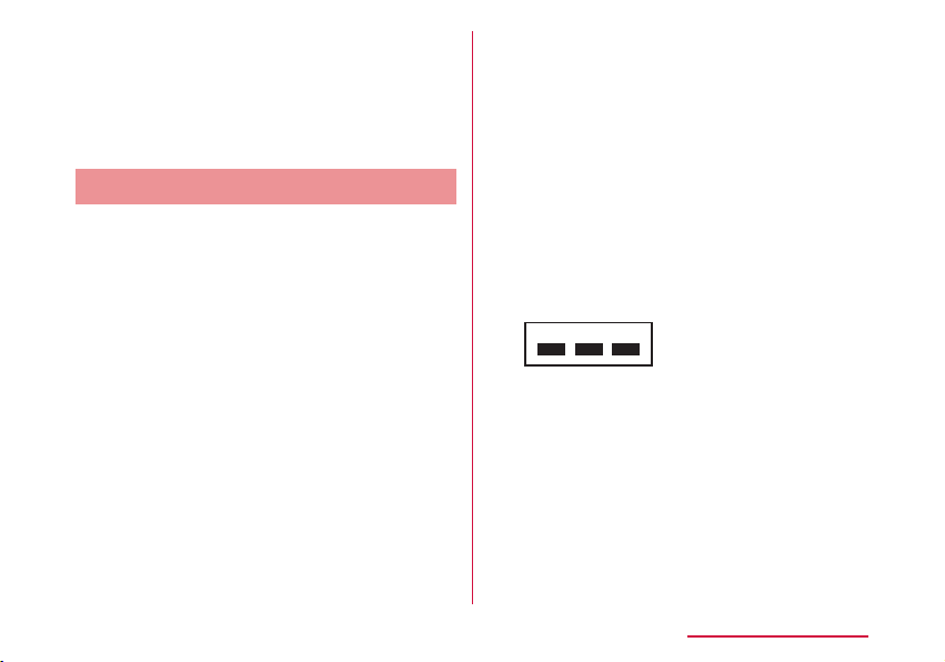
• Frequency band
The frequency band that the devices with
WLAN equipped uses is written on the
insertion part of the batter pack on the main
unit of this terminal. It shows how to read the
label below.
2.4DS4/OF4
2.4 : Indicates radio equipment
using 2,400 MHz.
DS : Indicates that modulation
methods are DS-SS format.
OF : Indicates that modulation
methods are OFDM format.
4 : Indicates that assumed
inducing interference from
distances is 40 m or less.
Contents/Precautions
27
Page 30

Available channels vary by the country.
For use in an aircraft, contact the airline
company beforehand.
• 2.4 GHz Bandwidth Cautions
The operating frequency band of the
WLAN device is used by home electrical
appliances such as microwave ovens,
industrial, scientic, consumer and medical
equipment including premises radio
stations for identifying mobile units used in
the manufacturing lines of plants stations
(radio stations requiring no license) and
amateur radio stations (radio stations
requiring a license).
1. Before using the device, conrm that
Contents/Precautions
28
: The full band between 2,400
MHz and 2,483.5 MHz is
used and the band of the
mobile identication device is
avoidable.
premises radio stations for identifying
mobile units, specied low power radio
stations and amateur radio stations are
not being operated nearby.
2. If the device causes harmful radio
interference to premises radio stations
for identifying mobile units, immediately
change the frequency band or stop use,
and contact "docomo Information Center"
on the back cover of this manual for
crosstalk avoidance, etc. (e.g. partition
setup).
3. If the device causes radio interference
to specied low power radio stations or
amateur radio stations, contact "docomo
Information Center" on the back cover of
this manual.
• 5 GHz Bandwidth Cautions
The channel numbers and frequency used in
Japan is shown as below.
W56
(5.5 to 5.7 GHz ban dwi dth / 100, 102, 104,
106, 108, 110, 112, 116, 118, 120, 122,
124, 126, 128, 132, 134, 136, 140 ch)
When using W56 of the Wi-Fi 5 GHz band, the
terminal may automatically change to another
channel in order to avoid interference with
weather radar. In this instance, communication
is temporarily disconnected (DFS function).
Wi-Fi 5 GHz band is available only in Japan.
Also, some devices may not support Wi-Fi 5
GHz band.
Page 31

Caution
■ Do not use a modied terminal. Using a
modied terminal results in violating Radio
law/Telecommunications Business Act.
This terminal has been complied with
the rules related to technical standard of
wireless equipment stipulated by Radio
law, as well as technical standard of device
stipulated by Telecommunications Business
Act. As a proof, "Technical standard
compliance mark
electric nameplate.
If this terminal is modied by turning the
screw to the left to disassemble, technical
standard compliance becomes invalid.
Please do not use this terminal during the
time when technical standard compliance
is being invalid, since you are in violation of
Radio law and Telecommunications Business
Act.
■ Do not make unauthorized modications to
the basic software.
Repairs may be refused if the software has
been modied.
■ Keep your body 15 mm away from this
terminal during data communication.
" is indicated in the
Contents/Precautions
29
Page 32

Before Using this Terminal
Part Names and Functions
Before Using this Terminal
30
Power button:
a
Press two seconds or longer to power on/o.
Press shortly to turn on/o the display.
LED indicator:
b
Lighting red: charging this terminal
Lighting green: nished charging
Flashing red: starting charging of mobile device
Display (touch panel)
c
External connection terminal:
d
Attach the supplied USB Cable L03, Converter
Cable for Charging L02, etc.
Strap hole
e
Page 33

FOMA/Xi main antenna
f
FOMA/Xi sub antenna
g
The sub antenna is used to improve the
communication quality by using multi antennas.
Wi-Fi main antenna
h
Wi-Fi sub antenna
i
The sub antenna is used to improve the
communication quality of Wi-Fi by using multi
antennas.
Back cover
j
You can see docomo mini UIM card slot after
removing the back cover and the battery pack.
*1 Antennas are built in this terminal. Covering
*2
:
*1
:
*1
:
*1
:
*1
:
around the antenna by the hand may affect
the quality.
*2 The glossy surface with the "Wi-Fi STATION"
logo cannot be removed.
Note
• Communication speed may slow down
inuenced by the antenna performance which
may go worse when you put this terminal
on a metal object, such as a steel desk or a
table.
• When using near an electrical device,
communication speed may slow down
aected by the electrical device.
Before Using this Terminal
31
Page 34

Using docomo mini UIM card
Notch
docomo mini UIM card is an IC card stores
a customer's information such as a phone
number. In this terminal, data communication
is not available without docomo mini UIM card
inserted. For details about the handling of
docomo mini UIM card, refer to the instruction
manual for docomo mini UIM card.
• Turn o the power and remove the battery
pack before attaching/removing docomo mini
UIM card (→P35 "Attaching" / P37
"Removing").
This terminal uses only docomo mini UIM card.
Bring your UIM/FOMA card to a docomo Shop
to exchange it.
Before Using this Terminal
32
Attaching
Insert docomo mini UIM card
a
underneath the docomo mini UIM
card slot guide in the direction of a
with its IC side facing down
IC (gold)
Notch
docomo mini UIM card
slot guide
Lock
Page 35

Removing
Push out 2 to 3 mm of the docomo
a
mini UIM card in the direction of
b while pressing the lock by your
ngertip (a)
Release your nger from the lock,
b
slightly hold the docomo mini UIM
card and slide it in the direction of c
Do not press down the docomo mini UIM card
hard
Lock
Note
• After removing, do not lose the docomo mini
UIM card.
• Do not touch the IC of docomo mini UIM card
and be careful not to get injured.
• Inserting the docomo mini UIM card with
wrong orientation may cause malfunction.
• docomo mini UIM card may get damage if
you put excessive force when attaching or
removing it.
Before Using this Terminal
33
Page 36

Security Code
■ PIN1 code
The docomo mini UIM card can set security
code named PIN1 code. "0000" is set at
the time of subscription. Customers can
change it afterwards (→P97 "Changing
password"). PIN1 code is a security code of
4- to 8-digit number you enter after powering
on this terminal to verify the user in order
to prevent unauthorized use of docomo mini
UIM card by a third party.
When you have set the PIN1 code for docomo
mini UIM card, data communication is not
available without PIN1 code verication.
Verify PIN1 code and start use, or set the
docomo mini UM card to not verify PIN1 code
(→P96) beforehand.
■ PIN Unlock code
PIN Unlock code is an 8-digit number used to
unblock the PIN1 code. You cannot change
it by yourself.
PIN Unlock code ten times in a row, the
docomo mini UIM card will be locked.
Before Using this Terminal
34
If you fail entering the correct
Display PIN1 code when powering on this
terminal or after login to setting page
(L-01G Connection Manager)
• When "PIN1 lock" on setting page is set to
"Locked" (→P96), enter PIN1 code.
Enter PIN1 code
Fail three times in a row
Enter PIN Unlock code
Enter it from setting page (→P97)
OK Fail 10 times in a row
Set a new PIN1
code
Contact a docomo
Shop.
Page 37

Caution
Back cover Groove
• Avoid setting PIN1 code to "your birthday",
"part of your phone number", "your address or
room number", "1111" or "1234", which can
be easily guessed by others. Take a memo of
PIN1 code to avoid forgetting.
• Do not reveal your PIN1 code to others.
DOCOMO is not responsible for damage
caused by misuse of your PIN1 code by
others.
• If you forget your PIN1 code, you need to
bring your identication document (driver's
license, etc.), this terminal and docomo mini
UIM card to a docomo Shop.
For details, contact "General Inquiries"
provided on the back cover of this manual.
• Your PIN unblocking key is written in the
application form (copy for subscriber)
given at the time of contract. If you have
subscribed at a place other than a docomo
Shop, bring your identication document
(driver's license, etc.), this terminal and
docomo mini UIM card to a docomo Shop, or
contact "General Inquiries" provided on the
back cover of this manual.
Attaching/Removing Battery Pack
Please use the dedicated battery pack L23 for
this terminal.
Attaching
Put your nger in the groove of
a
the back cover and hold it up in the
direction of the arrow to detach
Groove
Before Using this Terminal
35
Page 38

Align the battery pack with the metal
b
terminals of this terminal and attach
it in the direction of a with "
the battery pack facing up, and insert
in the direction of b
Align the tabs of this terminal with the dips on
the battery pack.
Tabs
Before Using this Terminal
36
" on
Conrm the orientation of the back
c
cover and align it with the main unit,
press the arrow parts one by one to
close the back cover rmly
Make sure that the grooves of the back cover
and main unit are on the same side.
Grooves
Page 39
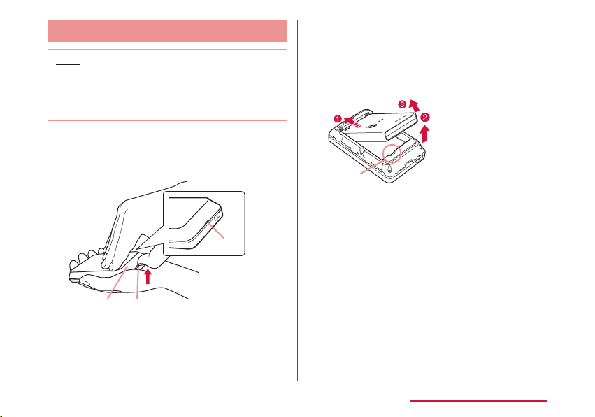
Removing
Back cover Groove
part
Note
• Make sure to turn o this terminal before
removing the battery pack. The operations
of this terminal may become improper if you
remove the battery pack with the power on.
Put your nger in the groove of
a
the back cover and hold it up in the
direction of the arrow to detach
Groove
Put your nger in the groove of this
b
terminal against the battery pack
and press in the direction of a. Lift
up in the direction of b and remove it
in the direction of c
Groove
Before Using this Terminal
37
Page 40

Charging
■ Battery Charge
• Do not apply excessive force when inserting
or pulling out the connector. Insert or pull it
out slowly.
• When charging with an entirely empty battery
pack, it may take a while to power on this
terminal.
• The internal of this terminal may become
warm and the charging may stop when data
communicating during charging. In that
case, turn o this terminal and wait until this
terminal cools down. Then charge it again.
• Depending on the usage conditions, charging
may stop before the battery level reaches
100%. In that case, remove the battery
pack and attach it again. You can continue
charging.
• Do not remove the battery pack while
charging. If you remove the battery pack
during charging, this terminal may not power
on properly, or it may not be able to charge.
In that case, remove the battery pack, cables
from this terminal and connect them again.
Before Using this Terminal
38
■ Do not charge this terminal for a prolonged
time with its power turned on.
• If you charge this terminal for a prolonged time
with its power turned on, the battery pack will start
supplying power to this terminal after nishing
charging. This will reduce the actual usage time
and deplete the battery. If this happens, please
charge it again correctly. When charging again,
remove this terminal rst and connect it again.
■ Usage time of battery pack and estimated
charging time
For details about usage time and charging
time, refer to "Main Specications" ( → P147).
■ Battery pack life
• Battery pack is a consumable supply. Every
time when you charge the battery, usable time
becomes short.
• When the usage time becomes about half
of a new battery, life of the battery pack is
assumed to be over. We recommend you to
replace the battery pack ahead of time. Also,
depending on the usage condition, the battery
pack may get swollen when the battery life is
running out. Note that it is not a problem.
• Data communicating while charging may
aect life of battery pack.
Page 41

■ AC adapter
External connection terminal
To AC 100 V outlet
• For details, refer to the instruction manual
of AC adapter 03/04/05/L02/L03/L04
(optional).
• AC adapter can be used from AC 100 V to
240 V.
• The shape of AC adapter plug is AC 100 V
(Japanese specication). A conversion plug
adapter for the destination country is required
when using an AC adapter compatible from
AC 100 V to 240 V. Also do not use a
transformer for overseas travel to charge.
■ DC adapter
• The DC adapter supplies power to charge this
terminal through a cigar lighter socket (12
V/24 V) in a vehicle.
• For details, refer to the instruction manual of
DC adapter 03/04.
Charging with AC Adapter
It describes how to charge this terminal with
AC adapter 05 (optional).
AC Adapter
LED indicator
Insert it into the external connection
a
terminal of this terminal horizontally
microUSB connector
(with B side facing up)
with the side of B mark on microUSB
connector of AC adapter facing up
Insert the power plug of AC adapter
b
into power outlet
LED indicator lights up red and the charging
starts.
After charging is completed, LED indicator
turns to lighting blue.
Power
plug
Before Using this Terminal
39
Page 42

When charging is completed, remove
c
the power plug of AC adapter from
the power outlet
Remove the microUSB connector
d
of AC adapter from this terminal
horizontally
Charging with PC
Connect this terminal to a PC with the supplied
USB cable L03 to charge this terminal on PC.
• About how to connect with a PC, refer to
"Attaching to/Removing from PC" (→P63).
• Depending on the condition of the PC, it may
take a while to nish charging, or it may not be
able to charge.
Before Using this Terminal
40
Power On/O
Power On
When the power is o, press the
a
power button for over two seconds
For rst time activating, "Startup Wizard" is
displayed. Follow the on-screen instructions.
The following settings are required when
using this terminal following the onscreen
instructions.
• Language
• Provider
• SSID
• Public WLAN
• Shortcut
Power button
Page 43

Note
• When it is powered on, mobile network search
such as Xi area or FOMA area starts. When
connected to network, the mobile network
name ("NTT DOCOMO" in Japan) is displayed.
Also when it is powered on, connection with
compatible Wi-Fi devices is available.
• Lock screen is displayed when activating
this terminal after setting "Startup Wizard".
(→P45)
Power O
When the power is on, press the
a
power button for over two seconds
"Yes"
b
Viewing Display
The following shows the meaning of each icon
displayed on the screen (press the power
button when it is not displayed (→P45)).
a b cde f g h
j
k
Receiving level
a
Strong Weak
: Out of service/mobile networks disconnected
:
Home screen
During international roaming
i
l
m
n
o
p
Before Using this Terminal
41
Page 44

Connected network type
b
: LTE network connected
: 3G network connected (HSDPA/
HSUPA, W-CDMA)
: GSM network connected
: Connecting via public wireless LAN
• During communicating,
(downloading) is displayed in whitely.
Public wireless LAN receiving level
c
Strong Weak
: PWLAN on
/ : USB tethering/pocket charging mode
d
: New software
e
Frequency band
f
g
h
i
Before Using this Terminal
42
: Wi-Fi frequency band is "2.4GHz"
: Wi-Fi frequency band is "5GHz"
: DFS check is in progress
Network sleep ON (→P103)
: Connected clients
• When Wi-Fi power save ( → P103) is set to
"OFF", the icon is displayed as
Remaining battery level
Full Empty
(uploading) or
(white).
: Charging
Flashing
: Battery is almost empty. Please
• While power save mode is activated
(→P103), the icon is displayed as
(green) /
Public WLAN
j
Tap this to switch public wireless LAN on and o.
When Wi-Fi is turned o, it cannot be turned on.
Shortcut (→P104)
k
Wi-Fi connection guide
l
Follow the on-screen instructions to connect
this terminal and Wi-Fi compatible device.
WPS
m
Use WPS to set up Wi-Fi.
Tap it to activate.
When Wi-Fi is turned o, it cannot be turned on.
Network display
n
Displays the current connected mobile network
name
Data communication amount display
o
(→P104)
Menu Tap to display menu screen.
p
charge.
(low: orange).
.
Page 45

■ Example of state display
It displays information such as the charging
state of the battery pack, the state of WiFi function and network name (the following
screens are examples).
Note
• Not like other smart phones, L-01G shows
the current time only when it can receive the
time information from the Internet. Therefore,
for the following cases it may not show the
current time correctly.
- Right after launching this terminal, from
out-of-service state to being connected to
network
- When accessing to the Internet overseas
Charging (only
when the
power is o)
Wi-Fi function
Disconnecting
WPS function
being
activated
Charging
mobile device
Wi-Fi function
Activating
Before Using this Terminal
43
Page 46

Basic Operations
How to Use Touch Panel
This terminal adopts touch panel which allows
you to operate by touching the panel.
Precautions on touch panel usage
The touch panel is designed for nger touching
lightly. Do not press it hard with your nger or
with sharp objects (ngernail, ballpoint pen, pin
etc.).
The following actions may cause the touch
panel not working properly. Note that it may
cause wrong operations.
• Operating the screen with gloved hands
• Operating the screen with tip of a ngernail
• Operating the screen with an object on it
• Operating the screen with a protective sheet or
seal on it
Before Using this Terminal
44
Operations of touch panel
The following operations are available on the
touch panel.
• Tap: Touch the screen lightly
• Touch and hold: Touch the screen for over one
second
• Scroll: Move your nger upwards and downwards
while touching the screen.
Page 47

Screen Unlock
Lock screen is displayed when pressing power
button after back light turned o, or when this
terminal is launched.
Press and hold "
About screen lock settings, refer to "Display"
(→P104).
" to unlock.
Menu Operations on this Terminal
Operate on the touch panel of this terminal to
set settings (→P101). For detailed settings,
use L-01G Connection Manager on PC to set up.
For details, refer to "Settings" (→P72).
Lock screen
Tap " ".
Tap each menu to
display the setting
screen.
" to return to
Tap "
upper tier.
" to return to the
Tap "
Home screen.
Before Using this Terminal
45
Page 48

Entering a Character
Operate on the touch panel of this terminal to
input the password (security key), etc.
a
b
c
d
Text box
a
Cancel key
b
Keyboard area
c
One key is assigned to multiple characters. Tap
the same key more than one time to input the
character you want.
Shift key
d
Switch capital letters and small letters.
OK key
e
Delete key
f
Clear the character on the left side of the cursor.
Space key
g
Enter a space.
Before Using this Terminal
46
Input switch key
h
Switch number/alphabet input.
Input switch key
i
Switch number/symbol input.
Tap keyboard area to input
a
characters
The selected characters are input in the text
e
f
g
h
i
box.
• Select character type from alphabet/
number/symbol and tap the character to
input.
• When entering letters which are assigned to
the same key consecutively, wait for one to
two seconds before entering the next letter.
Example: When entering "bc"
Tap "abc" key twice
a
After waiting for 1 to 2 seconds, tap "abc"
b
key three times.
After nishing input, tap "OK"
b
Note
• In this terminal, only single byte alphanumeric
characters, part of single byte symbols
~!@#$%^&*-_:,./;|()<>{}[]+=`"'?\
(
space can be input.
• Depending on the usage environment you
use, "\" may be displayed as "\" (backslash).
) and single byte
Page 49

Setting up
Setup
Using L-01G Connection Manager, you can
change the wireless LAN or settings of each
function of the Wi-Fi compatible device you use
depending on your usage environment.
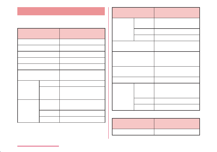
Conrming the Compatible Device
This terminal supports the following OS/device.
(as of February, 2015)
L-01G
OS/device
Windows 8.1*1 32bit/64bit ○
Windows 8
Windows 7 SP1 32bit/64bit ○
Mac OS X 10.10.1 64bit ○
Mac OS X 10.9.5 64bit ○
*1
32bit/64bit ○
Connection
Manager
operation
OS/device
Mac OS X 10.8.5 64bit ○
Mac OS X 10.7.5 32bit/64bit
Android terminal
*2
iPhone
*1 Windows RT is not included.
*2 "SYSTEM" of L-01G Connection
Manager→"Backup & Restore" function
cannot be used.
*2
/iPod touch*2/iPad
*2
Connection
Manager
operation
Setting up
L-01G
○
○
○
47
Page 50

Using Wi-Fi Compatible Device
• For Wi-Fi compatible devices which support
IEEE802.11a/n/ac (5 GHz) or IEEE802.11b/g/n
(2.4 GHz), you can connect it with this terminal
and start use.
• We do not guarantee any operations used on
your PC even when the operating condition
is matching. Operations may not be proper
depending on the usage environment you use,
such as the peripheral devices, application, etc.
• For operations or operating method of Wi-Fi
compatible device, contact source manufacturer.
• The supported OS/device information is shown
below. (as of February, 2015)
OS/device
Windows 8.1 32bit/64bit
Windows 8 32bit/64bit
Windows 7 SP1 32bit/64bit
Mac OS X 10.10.1 64bit
Mac OS X 10.9.5 64bit
Mac OS X 10.8.5 64bit
Mac OS X 10.7.5 32bit/64bit
Android terminal
Setting up
48
OS/device
iPhone/iPod touch/iPad
Nintendo DS
PlayStation
PSP
®
Vita "PS Vita"
®
"PlayStation® Portable"
Page 51

Using USB Cable
You can connect this terminal with a PC via the
supplied USB Cable L03 to use USB tethering.
The supported OS information is shown below.
(as of February, 2015)
OS
Windows 8.1 32bit/64bit Japanese/English
Windows 8 32bit/64bit Japanese/English
Windows 7 SP1 32bit/64bit Japanese/English
Mac OS X 10.10.1 64bit Japanese/English
Mac OS X 10.9.5 64bit Japanese/English
Mac OS X 10.8.5 64bit Japanese/English
Mac OS X 10.7.5 32bit/64bit Japanese/English
* Only Mac equipped with Intel CPU is supported.
Data communication is possible when charging
with USB Cable.
For operating environment of the latest
information, conrm DOCOMO website.
*
*
*
Note
• You may not be able to use depending on
your environment and device. Note that
we are not responsible for any inquiries
and operations used in other operating
environments.
*
Setting up
49
Page 52

Setup Flow
Connecting via Wi-Fi (→P51) Connecting via USB Cable (→P63)
・Setting on Windows PC (→ P55)
・Setting on Mac (→ P58)
・ Wi-Fi compatible device which supports
Wi-Fi (→P60)
・For provider setting (→ P77)
・For public wireless LAN setting (→ P78)
Setting up
50
・For Windows (→ P64)
Installing driver
・For Mac (→ P68)
Setting up with L-01G Connection Manager
Connecting to the Internet
Page 53

Note
• To change the settings of this terminal,
connect to a PC and change the settings
rst before connecting to other Wi-Fi
compatible devices.
* Also, for terminals support browser,
settings of the terminal main unit can be
changed not only with PC. However, part
of the menu cannot be used. Depending
on the browser, it may not be able to use.
For Wireless Connection
Setting procedures are dierent depending on the
Wi-Fi compatible device you use. Here it describes
setting procedures of each terminal below.
• Wi-Fi compatible device which supports WPS
(→P53)
• Windows PC (for Windows 8.1) ( → P55)
• Windows PC (for Windows 7) ( → P57)
• Mac ( → P58)
• Android ( → P60)
• iPhone/iPod touch/iPad ( → P60)
• Nintendo DS ( → P61)
• PS Vita ( → P61)
• PSP ( → P62)
Setting up
51
Page 54

Note
• For those settings, set them up when
connecting each terminal for the rst time.
Once it is set up, auto connection starts
after turning on this terminal.
• When connecting without using WPS
function, enter the SSID and security key
set up in this terminal (for this terminal,
"password (security key)" indicates "security
key"). (→P52) Conrm beforehand and set
the settings.
• Depending on the Wi-Fi compatible device,
"password (security key)" is referred as "Wi-Fi
password" or "password".
• Up to 10 Wi-Fi compatible devices can be
connected to this terminal at the same time.
• For Windows and Mac, log in by a user
account with administrator authority.
Setting up
52
■ Conrming SSID/Password (Security Key)
On the Home screen, tap "Connection
a
guide" → "Manual input"
SSID and password (security key), etc. are
displayed.
Note
• Conrm the SSID and password (security
key) from the bundled "SSID/security sticker".
Also SSID and password (security key) are
written on the sticker inside of the main unit
after removing the battery pack (→P35
"Attaching/Removing Battery Pack").
• You can also conrm from the setting menu
of this terminal. (→P109)
Page 55

■ SSID/Password (Security Key)
You can use two SSID on this terminal. For
default SSID, refer to the following.
Connecting Wi-Fi Compatible
Device Supports WPS
Primary SSID:
Use the "SSID:" written on the sticker. It can
be used in wireless LAN security mode which
is over WPA and the password (security key)
uses "SECURITY KEY:".
Secondary SSID:
Replace the "_A" at the end of the "SSID:"
written on the sticker with "_B". About the
settings of secondary SSID, refer to "Setting
Secondary SSID" (→P86).
Note
• Setting method is dierent depending on
the Wi-Fi compatible device. Refer to the
instruction manual of the Wi-Fi compatible
device you use to ensure your operations.
• When the PIN code of WPS function on the
Wi-Fi compatible device you use is specied,
select "PIN(From Client)" from "WPS type" on
this terminal and set the PIN code specied
in "PIN" beforehand. (→P87)
• When "Security(Encryption type)" ( → P84)
is set to "Auto(WEP)", WPS function cannot
be used.
• When "SSID Stealth" ( → P86) is set to
"On", WPS function cannot be used.
Setting up
53
Page 56

■ Example when "WPS type" is set to "Button"
Press the power button of this
a
terminal for over two seconds
This terminal is turned on and Wi-Fi function is
turned on.
Turn on Wi-Fi function on the Wi-Fi
b
compatible device being connected
and set up WPS function if necessary
Operate connection via WPS function
c
on the Wi-Fi compatible device being
connected
Tap "WPS" on this terminal
d
Follow the on-screen instructions on
e
the Wi-Fi compatible device being
connected to set up
Setting up
54
■ Example when "WPS type" is set to
"PIN(From AP)"
Press the power button of this
a
terminal for over two seconds
This terminal is turned on and Wi-Fi function is
turned on.
Activate Web browser on the PC
b
connected to the Internet, log in to
the setting page of this terminal
(L-01G Connection Manager)
Click "WPS" on the setting page
c
(L-01G Connection Manager) you
logged in, select "PIN(From AP)" in
the "WPS type" eld
Click "Create" in the PIN eld on the
d
WPS setting page and create WPS PIN
An 8-digit WPS PIN code is displayed.
Turn on Wi-Fi function on the Wi-Fi
e
compatible device being connected
and enter the 8-digit WPS PIN code in
"WPS-PIN"
When check mark is displayed on this terminal,
access to WPS is successful.
Page 57

■ Example when "WPS type" is set to
"PIN(From client)"
Press the power button of this
a
terminal for over two seconds
This terminal is turned on and Wi-Fi function is
turned on.
Activate Web browser on the PC
b
connected to the Internet, log in to
the setting page of this terminal
(L-01G Connection Manager)
Click "WPS" on the setting page
c
(L-01G Connection Manager) you
logged in, select "PIN(From client)" in
the "WPS type" eld
Turn on Wi-Fi function on the Wi-Fi
d
compatible device being connected
and select "WPS-PIN" access
An 8-digit WPS PIN code is displayed on the
Wi-Fi compatible device side.
Enter the 8-digit number displayed on
e
the Wi-Fi compatible device side in the
PIN eld of WPS
setting page on the setting page
(L-01G Connection Manager) you
logged in, click "Start"
When check mark is displayed on this terminal,
access to WPS is successful.
Connecting Windows PC
The setting procedures described here is
an example when the security mode of this
terminal is set to the default setting of "WPA/
WPA2-PSK(AES+TKIP)".
For Windows 8.1
Press the power button of this
a
terminal for over two seconds
This terminal is turned on and Wi-Fi function is
turned on.
Turning on Wi-Fi function on PC
b
Setting up
55
Page 58

56
On the desktop screen, swipe from
c
the right side of the screen (point
the top right of the screen in case of
mouse) → from charm, click
Click to display the Network list
d
screen
Click the password (security key)
e
of this terminal (Default: "L01G_
XXXXXXXX_A" →P52) and click
"Connect"
Setting up
Enter the password (security key)
f
set in this terminal ( → P52) in
"Network security key" and click "OK"
When the PC sharing selection is
g
displayed, click "Yes".
Page 59

For Windows 7
Press the power button of this
a
terminal for over two seconds
This terminal is turned on and Wi-Fi function is
turned on.
Turning on Wi-Fi function on PC
b
Click (Start) → "Control Panel" →
c
"Network and Internet" → "Network
and Sharing Center"
"Network and Sharing Center" window is
displayed.
Click "Connect to a network"
d
Click the displayed SSID of this
e
terminal (default setting: "L01G_
XXXXXXXX_A"→P52) and click
"Connect"
Enter the password (security key)
f
set in this terminal in "Security Key"
( → P52) and click "OK"
Setting up
57
Page 60

Connecting Mac
The setting procedures in Mac OS X 10.10.1
described here is an example when the security
mode of this terminal is set to the default
setting of "WPA/WPA2-PSK(AES+TKIP)"
(Encryption scheme supports AES and TKIP).
Press the power button of this
a
terminal for over two seconds
This terminal is turned on and Wi-Fi function is
turned on.
"System Preferences..." on apple
b
menu → "Network"
Setting up
58
Select "Wi-Fi" and click "Turn Wi-Fi On"
c
Wi-Fi function on Mac is turned on.
Note
• When "Used network cannot be found."
is displayed, click "Cancel" and then "Ask
before joining new networks" to cancel the
selection.
Page 61

Click "Network Name" and select
d
the displayed SSID of this terminal
(default setting: "L01G_XXXXXXXX_
A" →P52)
Enter the password (security key)
e
( → P52) set in this terminal in
"Password", select "Remember this
network" and click "Join"
Setting up
59
Page 62

Connecting Android
The setting procedures in Android described
here is an example when the security mode
of this terminal is set to the default setting
of "WPA/WPA2-PSK(AES+TKIP)" (Encryption
scheme supports AES and TKIP).
Press the power button of this
a
terminal for over two seconds
This terminal is turned on and Wi-Fi function is
turned on.
From the Home screen of Android,
b
"Menu" → "Settings"
"Wi-Fi" → Tap Wi-Fi switch to turn Wi-
c
Fi "ON"
Tap the displayed SSID of this
d
terminal (default setting: "L01G_
XXXXXXXX_A" →P52)
Enter the password (security key)
e
( → P52) set in this terminal, tap
"Connect"
Setting up
60
Connecting iPhone / iPod touch /
iPad
The setting procedures described here is
an example when the security mode of this
terminal is set to the default setting of "WPA/
WPA2-PSK(AES+TKIP)" (Encryption scheme
supports AES and TKIP).
Press the power button of this
a
terminal for over two seconds
This terminal is turned on and Wi-Fi function is
turned on.
From iPhone/iPod touch/iPad home
b
screen, tap "Settings"
Tap "Wi-Fi" and turn Wi-Fi "ON"
c
Tap the displayed SSID of this
d
terminal (default setting: "L01G_
XXXXXXXX_A" →P52).
Enter the password (security key)
e
( → P52) set in this terminal, tap
"Join"
Page 63

Connecting Nintendo DS
The setting procedures in Nintendo 3DS
described here is an example when the security
mode of this terminal is set to the default
setting of "WPA/WPA2-PSK(AES+TKIP)"
(Encryption scheme supports AES and TKIP).
Press the power button of this
a
terminal for over two seconds
This terminal is turned on and Wi-Fi function is
turned on.
From HOME menu of Nintendo 3DS, "本
b
体設定 (Unit settings)" → "はじめる (Start)"
→ "インターネット設定 (Internet settings)"
"インターネット接続設定 (Internet
c
connection settings)" → "接続先の登録
(Register access point)"
"自分で設定する (Set manually)"
d
"アクセスポイントを検索 (Search an
e
access point)"
Touch the displayed SSID of this
f
terminal (default setting: "L01G_
XXXXXXXX_A" →P52)
Enter the password (security key)
g
(→ P52) set in this terminal, touch "
決定 (OK)"
"OK"
h
Settings are saved.
"OK"
i
Connection test starts.
Connecting PS Vita
The setting procedures in PCH-2000 described
here is an example when the security mode
of this terminal is set to the default setting
of "WPA/WPA2-PSK(AES+TKIP)" (Encryption
scheme supports AES and TKIP).
Press the power button of this
a
terminal for over two seconds
This terminal is turned on and Wi-Fi function is
turned on.
On the Home screen of PS Vita, touch
b
"設定 (Settings)" → "はじめる (Start)"
Touch "Network" → "Wi-Fi"
c
Mark "Wi-Fi"
d
Setting up
61
Page 64

Touch the displayed SSID of this
e
terminal (default setting: "L01G_
XXXXXXXX_A" →P52)
Enter the password (security key)
f
(→ P52) set in this terminal, touch
"OK"
Return to the Wi-Fi setting screen. Conrm if
SSID of this terminal is connected via Wi-Fi.
Connecting PSP
The setting procedures in PSP-3000 described
here is an example when the security mode
of this terminal is set to the default setting
of "WPA/WPA2-PSK(AES+TKIP)" (Encryption
scheme supports AES and TKIP).
Press the power button of this
a
terminal for over two seconds
This terminal is turned on and Wi-Fi function is
turned on.
Switch on PSP wireless LAN
b
From the Home screen of PSP,
c
"Settings" → "Network settings" and
press " ○ " button
Setting up
62
Select "Infrastructure Mode" and
d
press " ○ " button
Select "New Connection" and press
e
"○ " button
Select "Scan" and press the direction
f
key "△" button
Select the displayed SSID of this
g
terminal (default setting: "L01G_
XXXXXXXX_A" →P52) and press
"○ " button.
Conrm the SSID displayed and press
h
the direction key of "△" button
Select "WPA-PSK (TKIP)" or "WPA-
i
PSK (AES)" and press the direction
key of "△" button
• Security of "WPA-PSK (AES)" becomes high.
Press "○" button
j
Enter the security key ( → P52)
k
set in this terminal and press the
direction key of "△" button
Page 65

LED indicator
microUSB connector
connector
Select "Easy" and press the direction
l
key of "△" button
Conrm the connection name
m
displayed and press the direction key
of "△" button
Conrm the setting list displayed and
n
press the direction key of "△" button
Press "○" button
o
Settings are saved.
Press "○" button
p
Connection test starts.
For USB Connection
Attaching to/Removing from PC
Use the supplied USB Cable L03 to attach to a
PC.
• Note that if you remove the USB cable from a PC
during data communication, data communication
is disconnected and false operations or loss of
data may result.
Attaching
USB
USB Cable
Power on the PC
a
Setting up
63
Page 66

Insert the microUSB connector of
b
the USB cable into the external
connection terminal of this terminal
horizontally with the USB mark facing
up
Insert the USB connector of USB
c
cable to the USB port of PC
• LED indicator lights up red and the charging
starts.
Removing
Remove USB cable from the USB
a
port of PC and external connection
terminal of this terminal horizontally
Installing Driver (Windows PC)
When connecting for the rst time after
purchase, setup screen of L-01G driver is
displayed automatically via zero installation
only for Windows version. Follow the on-screen
instructions to install.
• After installation, on the desktop screen,
shortcut of L-01G Connection Manager is
generated.
Setting up
64
Note
• Do not cancel or remove this terminal during
installation of the driver.
• When performing installing operation,
make sure that the OS has started before
connecting this terminal to the USB terminal
of PC.
• Do not cancel or remove this terminal during
installation.
• Depending on the PC, it may take longer for
installation.
• 6.5 MB or more of free disk space is required
for installation (may dier depending on the
usage environment).
• Do not perform installation or uninstallation
while sending or receiving data.
• Before installation, stop all the running
applications and resident programs including
virus check software.
• Always use the administrator's user account
to perform the installation. Installation with
other account causes errors.
• For the operation of administrator setting,
contact the PC manufacturer or Microsoft.
Page 67
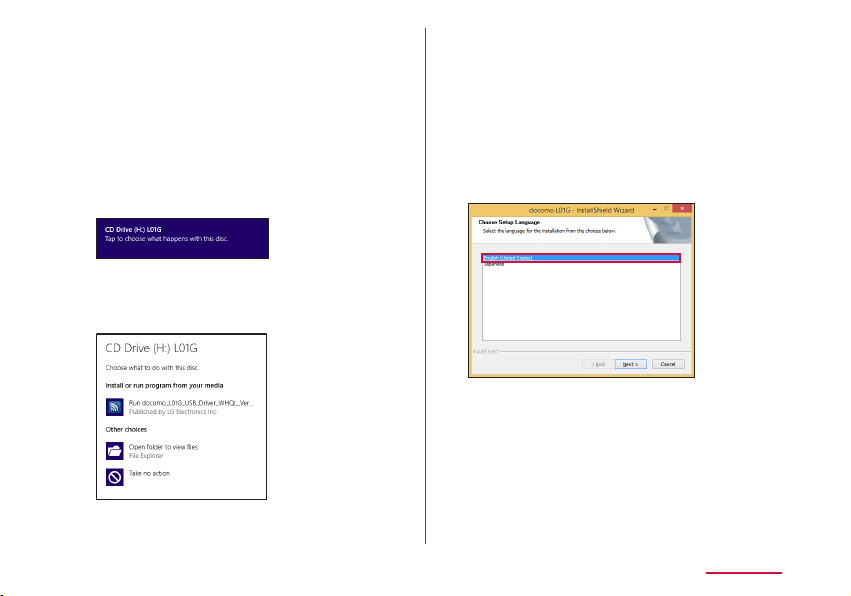
Screen displays are taken from Windows 8.1 as
example.
Press the power button of this
a
terminal for over two seconds
This terminal is turned on and Wi-Fi function is
turned on.
Click "CD Drive (X:) DOCOMO" (X part
b
diers depending on the PC) on the
top right
• The procedure is not necessary for Windows 7.
Click "Run docomo_L01G_USB_
c
Driver_WHQL_Ver_X.X.X.exe"
• When user account control screen is
displayed, click "Yes".
• If the installer does not start automatically
If the installer does not start automatically
even when connecting this terminal, press
"Windows" key and "E" on the keyboard to
display the Explorer screen, and doubleclick "CD Drive (X:) L01G" (X part diers
depending on the PC).
Select "English (United States)" and
d
click "Next"
Setting up
65
Page 68

66
Select "I accept the terms of the
e
license agreement" and click "Next"
When "Welcome to the InstallShield
f
Wizard for docomo L01G" is displayed,
click "Next"
Installation starts.
Setting up
Select "Optimize communication
g
settings (W-TCP Setting)
(Recommended)" and click "Next"
Click "Finish"
h
Page 69

Conrming the Installed L-01G Driver
Conrm if L-01G driver is set in PC. Connect
L-01G with a PC via the supplied USB Cable
beforehand.
Screen displays are taken from Windows 8.1 as
example.
On the desktop screen, swipe from
a
the right side of the screen (point
the top right of the screen in case of
mouse) → from charm, (Setting)
→ click "Control Panel" → "Hardware
and Sound"
• For Windows 7, (Start) → "Control Panel"
→ "System and Security".
Click "Device Manager"
b
Click each device display and conrm
c
the installed driver name
• Network adapters: docomo L01G USB NDIS
Device
• Ports (COM & LPT): docomo L01G USB
Serial Port (COMX)
• Modems: docomo L01G Modem
• Universal Serial Bus controllers: USB
Composite Device
Setting up
67
Page 70

Note
• After inserting this terminal to the USB
port of PC, if this terminal is not recognized,
insert with another USB port and conrm it.
Depending on the PC, this terminal may not
be recognized with certain USB ports.
• This terminal's driver does not support
Windows Store. Even for Windows 8.1/8,
installation or uninstallation is performed on
the desktop screen. Also, the shortcut icon
is displayed only on the desktop screen after
installation.
Click (Finder) → "Device" → "
b
→ "
L01G USB Driver
"
L01G
"
Installing Driver (Mac)
Screen displays are taken from Mac OS X
10.10.1 as example.
Press the power button of this
a
terminal for over two seconds
This terminal is turned on and Wi-Fi function is
turned on.
Setting up
68
• When screen related to "reliability of
software source" is displayed, click
"Continue".
Page 71

Click "Continue"
c
Click "Continue"
d
• When you agree on "Software License
Agreement", click "Agree".
• When "Change Install Location" screen is
displayed, select an installation destination
and click "Continue".
Click "Install"
e
Authentication screen is displayed.
Enter the Mac name (user name) and
f
password, and click "Install Software"
Setting up
69
Page 72

70
Click "Continue Installation"
g
Installation starts.
Click "Restart" on the installation
h
complete screen
PC restarts automatically. The installation is
completed. Remove this terminal from the PC
for a moment.
Setting up
Conrming the Installed L-01G Driver
"About This Mac" on apple menu →
a
"Overview" tab
Click "System Report..."
b
Click "USB" and check that "docomo
c
L01G" is displayed
Page 73

Setting Each Item
Activate Web browser on the PC connected
by Wi-Fi and display the setting page of this
terminal. Change the settings according to
the usage environment of settings on this
terminal.
• It can also be set via USB tethering on a PC.
In that case, set "USB tethering" to "ON" in the
setting menu of this terminal. (→P109)
* Also, for terminals support browser, settings of
the terminal main unit can be changed not only
with PC. However, part of the menu cannot be
used. Depending on the browser, it may not be
able to use.
For details, refer to "Settings (Web browser)"
(→P72) or "Settings (setting menu on this
terminal)" (→P101).
Setting up
71
Page 74

Settings (Web browser)
Logging in to the Setting Page (L-01G Connection Manager)
Activate Web browser on the PC connected
by Wi-Fi and display the setting page
(L-01G Connection Manager) of this terminal.
You can set up each function.
• Only the Wi-Fi compatible devices connected
to primary SSID can log in to the setting page.
The Wi-Fi compatible devices connected to
secondary SSID cannot log in.
• For PC, it can also be set via USB tethering. In
that case, set "USB tethering" to "ON" in the
setting menu of this terminal. (→P109)
• Depending on the items, the same settings can
be made in the setting menu of this terminal.
• L-01G Connection Manager cannot be
displayed or set on multiple PCs or terminals
simultaneously.
Settings (Web browser)
72
• While displaying other than the Home screen on
this terminal, some items are restricted settings
of L-01G Connection Manager. Also, while
setting with L-01G Connection Manager, the
operation from the menu of this terminal may be
disabled.
• The screen indicating that this terminal logs
in again after saving the setting may appear.
Follow the on-screen instructions.
Page 75

Note
• For terminals support browser, settings of
the terminal main unit can be changed not
only with PC. However, part of the menu
cannot be used. Depending on the browser,
it may not be able to use.
• The setting page on this terminal supports
the following Web browsers.
Windows: Microsoft Internet Explorer 7.0
or later, Firefox 19 or later,
Opera 12.0 or later, Google
Chrome 28 or later
Mac OS X: Safari 5.0 or later
Android: Basic browser
iOS: Basic browser
* Depending on the browser you use,
screens or items may not be able to
display.
* In browser settings, set Cookie to valid
(Save, accept).
* In browser settings, set Cache to invalid
(Not save, always conrm).
Press the power button of this
a
terminal for over two seconds
This terminal is turned on and Wi-Fi function is
turned on.
Activate PC and turn on Wi-Fi
b
function
This terminal is connected with the PC via WiFi.
• For the rst time connection, setup of Wi-Fi
connection is necessary. Refer to "For
Wireless Connection" (→P51) and set it
up.
Activate Web browser, enter
c
"http://192.168.225.1/" in address
input eld and press Enter key
"Login" screen is displayed.
• When L-01G driver is installed on the
Windows PC, double click the shortcut of
L-01G Connection Manager on the desktop
screen and display "Login" screen.
• "192.168.225.1" is the default setting of
the private UP address of this terminal.
When changing the setting, enter the private
IP address you set up (→P90 "Setting
DHCP function").
Settings (Web browser)
73
Page 76

Enter the login password (default:
d
"1234") in "Password" eld and click
"Login"
• "Admin" is displayed in "Username" eld. You
cannot change the setting.
• In "Language" eld, select a language
displayed in setting page.
Settings (Web browser)
74
■ When setting PIN1 code
PIN1 code conrmation screen is displayed.
Click "Refresh", unlock PIN1 code on this
terminal and log in again.
Note
• To ensure the security, we recommend
change the default login password. For
detailed information, refer to "Changing Login
Password" (→P98).
Page 77
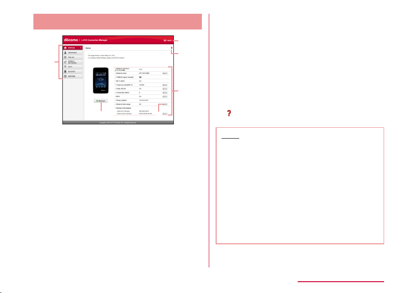
Screen of Setting Page
a
e
Top menu
a
Click a menu item and switch to the setting
page.
You can select the following items.
• STATUS ( → P76)
• PROVIDER ( → P77)
• PWLAN ( → P78)
• MOBILE NETWORK ( → P80)
• Wi-Fi ( → P82)
• ROUTER ( → P91)
• SYSTEM ( → P96)
d
b
f
c
"Logout"
b
Click it when logging out from the setting page.
Setting screen
c
Setting items of the function you selected in
menu item are displayed.
"EDIT"
d
Click it when changing the settings.
"Refresh"
e
Click it when refreshing the display content in
"Status" screen.
f
Help is displayed.
Note
• In L-01G Connection Manager, only single
byte alphanumeric characters, part of
single byte symbols (~!@#$%^&*-_:,./;|()<>{}
[]+=`"'?\) and single byte space can be input.
• Depending on the usage environment you
use, "\" may be displayed as "\" (backslash).
• For Mac OS, press "option" key and "\" to
enter "\".
• For Windows OS, press "\" to enter "\".
• For other devices, refer to the instruction
manual of the device you use.
Settings (Web browser)
75
Page 78
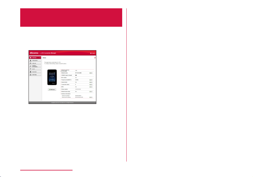
Conrming Connection State or
Setting State of this Terminal
Click "STATUS" of the top menu
a
"Status" screen is displayed.
• Click "Refresh" to refresh the information.
Network
selection
(LTE/3G/GSM)
Network name*: The mobile network name being
FOMA/Xi signal
*
strength
Wi-Fi status :
Settings (Web browser)
76
:
The mobile network type
(LTE/3G/GSM) being connected
*
is displayed.
connected is displayed.
: The current reception level is
displayed.
Wi-Fi function status is
displayed.
Frequency band
(Wi-Fi)
Public WLAN :
Connected
clients
WPS :
Phone number*: The phone number of docomo
Network data
*
usage
Interface
information
* When docomo mini UIM card is not inserted,
this item is not displayed. Also, "-" is displayed
in "Phone number" eld, and "DOCOMO mini UIM
card has not been inserted properly or is invalid."
is displayed in "Status" screen.
:
The frequency band used to
access to wireless LAN is
displayed.
The setting status of the
connection function accessing
to the public wireless LAN is
displayed. When connecting
via public wireless LAN, the
name of the access point being
connected is displayed.
: The number of the terminals
connected via Wi-Fi currently is
displayed.
The setting status of WPS is
displayed.
mini UIM card is displayed.
: The setting status of whether
to show data communication on
this terminal is displayed.
: IP address, MAC address, etc.
are displayed.
Page 79

Setting Provider
Adding Access Point
Register, edit and delete an access point. Up
to 10 access points can be registered.
• The settings for connecting to mopera U preset
at the time of purchase cannot be deleted. When
using mopera U, the following settings are not
necessary.
• For details about mopera U, visit DOCOMO
website.
Click "PROVIDER" on the top menu
a
When registering a new access point,
b
click "Add New"
Set up each item in setting screen
c
Prole name
Enter a name of the access point within the
following range.
• Up to 15 characters of single byte
alphanumeric characters, symbol
(~!@#$%^&*-_:,./;|()<>{}[]+=`"'?\) and single
byte space
Access point name
Enter a name of APN within the following
range.
• Up to 99 characters of single byte
alphanumeric characters, symbol
(~!@#$%^&*-_:,./;|()<>{}[]+=`"'?\) and single
byte space
Username
Enter a user name specied by provider
within the following range.
• Up to 64 characters of single byte
alphanumeric characters, symbol
(~!@#$%^&*-_:,./;|()<>{}[]+=`"'?\) and single
byte space
Password
Enter a password specied by provider within
the following range.
• Up to 32 characters of single byte
alphanumeric characters, symbol
(~!@#$%^&*-_:,./;|()<>{}[]+=`"'?\) and single
byte space
Settings (Web browser)
77
Page 80

Authentication
Select an Authentication for the access point.
• None
• PAP
• CHAP
When registering a new access point,
d
click "Save"
Click "Apply" to save the settings
e
Note
• The registered prole name cannot be changed.
When changing prole name, delete the prole
and register again.
■ When setting a registered access point to
prole
Select an access point set to profile in "Profile
a
selection"
Click "Apply"
b
■ Edit an existing access point and set up the prole
Select an access point in "Profile selection" to
a
edit
Edit the item you want to change the setting
b
Click "Apply"
c
■ Delete an access point
Select an access point in "Prole selection" to delete
a
Click "Delete"
b
Click "OK"
c
Settings (Web browser)
78
Setting Public Wireless LAN
You can connect to wireless LAN router at
home or at work, or connect to the public
wireless LAN service outside to access to the
Internet.
• When using the public wireless LAN service, a
separate subscription or settings are required.
Contact the service provider you use for detailed
setting information etc.
Click "PWLAN" of the top menu
a
Set up each item in setting screen
b
Public WLAN
Set whether to use the connection function
to access to the public wireless LAN.
• On
• O
Page 81

■ When using
Display mode
Switch SSID display settings.
• Used networks: Displays all the access
points.
• Registered networks: Search and display
the registered access point as the AP
specied by user.
Searching result
Click "Scan" to display the available access
points in list.
: Connect to an access point.
•
: Disconnect the access point being
•
connected.
•
: Up to 10 access points can be
registered as the AP specied by user.
Access history
Up to 10 connection histories to the access
point are displayed.
•
: Delete an access point.
: Change the settings of an access point.
•
(Increase priority)/ (Decrease priority):
•
Change the priority order when connecting
to an access point. The upper line in the list
is higher priority than the lower line.
Add network
Add an access point. Set "AP name" and
"Security", click "Save".
■ When setting to WEP
Password
Enter password (security key) for WEP.
5, 10, 13 and 26 single byte alphanumeric
characters can be input as a key.
• For key of 5 to 13 characters, single byte
alphanumeric characters (0 to 9, a to z, A to
Z), symbol (~!@#$%^&*-_:,./;|()<>{}[]+=`"'?\)
and single byte space
• For 10 characters or 26 characters, hex
number (0 to 9, a to f, A to F)
■ When setting to WPA/WPA2-PSK
Password
Enter an 8 to 64 characters for password
(security key) of WPA/WPA2.
• For key of 8 to 63 characters, single byte
alphanumeric characters (0 to 9, a to z, A
to Z) and symbol (~!@#$%^&*-_:,./;|()<>{}
[]+=`"'?\)
• For key of 64 characters, hex number (0 to
9, a to f, A to F)
■ When setting to EAP-SIM
Auto authentication, no specic settings.
■ When setting to EAP-AKA
Auto authentication, no specic settings.
Settings (Web browser)
79
Page 82

When selecting an access point
c
from "Searching result", enter the
password (security key)
Click "Apply" to save the settings
d
Settings (Web browser)
80
Setting Network
Selecting an Access Point
You can specify the mobile network of the
access point. (→P113)
Displaying Data Communication Amount
Data amount used for communication is
displayed. Data communication amount
overseas is not counted. Also, data
communication during international roaming is
not displayed.
Click "MOBILE NETWORK" on the top
a
menu
Click "Network data usage" of the
b
sub menu
Page 83

Set up each item in setting screen
c
Current data usage
Click "Refresh" to check the latest
information.
Click "Reset" to clear the usage amount
information.
For the following case, the usage amount is
reset automatically.
• First of each month 0 o'clock
• When replacing docomo mini UIM card
• When resetting this terminal
Display mode
• Used data only: Data communication
amount is displayed on this terminal.
• Used data with max data: The current
usage amount and the upper limit of data
communication amount are displayed on
this terminal.
• O: Data communication amount is not
displayed on this terminal.
Maximum data size
Select "Used data with max data" in "Display
mode" to input.
Enter valid value
* Valid value: positive integer of 1 to 99
Invalid value: numbers other than minus, 0,
decimal point and valid value
* Even if the top data communication
amount is set, the communication is not
stop when it reaches the top limit amount.
Use as an estimate standard.
Click "Apply" to save the settings
d
*
.
Settings (Web browser)
81
Page 84

Advanced Settings of Wireless LAN
Note
• When using Wi-Fi function overseas, conrm
conditions such as available frequency or
regulations of the country to use it.
Setting Basic Functions of Wi-Fi
Click "Wi-Fi" of the top menu
a
Click "Basic setting" of the sub menu
b
Set up each item in setting screen
c
Settings (Web browser)
82
Frequency band
Set the frequency band you use.
• 2.4GHz
• 5GHz
SSID/Password Display on modem
Set whether to display the password
(security key) in "Basic setting" of the
setting menu on this terminal.
• On
• Display SSID only
• O
Privacy separator
Set if communication between clients
connected to dierent SSID is available.
When Privacy separator is set to valid,
communication between Wi-Fi compatible
devices connected to dierent SSID and
communication between PCs connected via
USB tethering are not available. Also, the
Connection Manager cannot be started from
the PC connected via USB tethering.
• On
• O
* Communication between Wi-Fi compatible
devices connected to the same SSID is
not aected.
DTIM period(100ms)
Enter the DTIM period. Use with the default
setting normally.
Page 85

Wi-Fi MIMO
Select whether to use MIMO function.
• On
• O
■ 2.4GHz setting
Wi-Fi Channel
Select a channel of wireless LAN.
* When connected to public wireless LAN, it
changes to the channel of the connected
access point automatically.
In Japan and Korea, Auto or a channel
between 1 to 13 is available. in other
countries, Auto or a channel between 1 to
11 is available.
Wi-Fi mode
Select an operation mode of wireless LAN.
• 11b only
• 11b/g
• 11g only
• 11n only
• 11b/g/n
* Select "Auto(WEP)" in "Security(Encryption
type)" (→P85) to set "11b/g". The
setting becomes the same when selecting
"Auto(WEP)" in "Security(Encryption type)" of
secondary SSID.
Wi-Fi bandwidth
Select wireless LAN bandwidth.
• 20MHz
• 20/40MHz: Available to select only when
"Wi-Fi mode" is set to "11n only" or "11b/g/
n".
■ 5GHz setting
Wi-Fi mode
Select an operation mode of wireless LAN.
• 11a only
• 11n only
• 11ac only
• 11a/n
• 11/a/n/ac
* Select "Auto(WEP)" in "Security(Encryption
type)" (→P85) to set "11ac only". The
setting becomes the same when selecting
"Auto(WEP)" in "Security(Encryption type)" of
secondary SSID.
Wi-Fi bandwidth
Select wireless LAN bandwidth.
• 20MHz
• 20/40MHz: Available to select only when
"Wi-Fi mode" is not set to "11a only".
• 20/40/80MHz: Available to select only
when "Wi-Fi mode" is set to "11ac only" or
"11a/n/ac".
Click "Apply" to save the settings
d
When using the Wi-Fi 5 GHz band, the terminal
is connected to the network after DFS check
starts to conrm that there is no interference.
Settings (Web browser)
83
Page 86

Note
• It takes about one minute* for DFS check.
While DFS check is in progress, the network
is temporarily disconnected. After conrming
that there is no interference, the terminal is
reconnected automatically. Any Wi-Fi devices
are also disconnected from the terminal.
Operate the devices to reconnect as required
after the terminal is reconnected to the
network.
* It may take longer depending on the DFS
check result.
• When DFS check starts, a message is
displayed on this terminal. Tap "Cancel" under
the message to stop DFS check and connect
via Wi-Fi 2.4 GHz band. Tap "Continue" to
close the message and continue DFS check.
Settings (Web browser)
84
Setting Security Mode of
Wireless LAN
Click "Wi-Fi" of the top menu
a
Click "SSID setting" of the sub menu
b
Set each item of primary SSID in
c
setting screen
SSID
Enter SSID name within the following range.
• Up to 32 characters, single byte
alphanumeric characters (0 to 9, a to z, A
to Z) and symbol (~!@#$%^&*-_:,./;|()<>{}
[]+=`"'?\) and single byte space
Page 87

Security(Encryption type)
Setting security mode of wireless LAN.
• Open(None)
• Auto(WEP)
• WPA2-PSK(AES)
• WPA/WPA2-PSK(AES+TKIP)
The setting items are dierent depending on
the settings of security mode.
■ When setting to Open(None)
No special settings.
■ When setting to Auto(WEP)
Password
Enter password (security key) for WEP.
5, 10, 13 and 26 single byte alphanumeric
characters can be input as a key.
• For key of 5 to 13 characters, single byte
alphanumeric characters (0 to 9, a to z, A to
Z), symbol (~!@#$%^&*-_:,./;|()<>{}[]+=`"'?\)
and single byte space
• For 10 characters or 26 characters, hex
number (0 to 9, a to f, A to F)
■ When setting to WPA2-PSK(AES)
Password
Enter an 8 to 64 characters for password
(security key) of WPA2.
• For key of 8 to 63 characters, single byte
alphanumeric characters (0 to 9, a to z, A to
Z), symbol (~!@#$%^&*-_:,./;|()<>{}[]+=`"'?\)
and single byte space
• For key of 64 characters, hex number (0 to
9, a to f, A to F)
Key update cycle(sec)
Set Key update cycle of encryption key
(password).
■ When setting to WPA2-PSK(AES+TKIP)
Password
Enter an 8 to 64 characters for password
(security key) of WPA/WPA2.
• For key of 8 to 63 characters, single byte
alphanumeric characters (0 to 9, a to z, A to
Z), symbol (~!@#$%^&*-_:,./;|()<>{}[]+=`"'?\)
and single byte space
• For key of 64 characters, hex number (0 to
9, a to f, A to F)
Key update cycle(sec)
Set Key update cycle of encryption key
(password).
Settings (Web browser)
85
Page 88

Max number of clients
Select the number of devices connected to
this terminal.
AP isolation
Set whether to allow the communication
between devices connected to the same
SSID.
SSID Stealth
Set SSID not to be detected by other
devices.
Secondary SSID
When using secondary SSID, set "Secondary
SSID" to "On".
Click "Apply" to save the settings
d
Settings (Web browser)
86
Setting Secondary SSID
Use secondary SSID function to connect the
Wi-Fi compatible devices with dierent security
modes at the same time. For Wi-Fi compatible
devices supporting WEP or Open, such as a
game machine, connect to secondary SSID.
When "Max number of clients" (→P86) of
primary SSID is set to "10", secondary SSID
cannot be used. (The number of the terminals
that can be set to secondary SSID is equal to
"the maximum number of clients (10)" - "the
number set in primary SSID".)
• The setting items are dierent depending on the
settings of wireless LAN security.
Click "Wi-Fi" of the top menu
a
Click "SSID setting" of the sub menu
b
Set "Secondary SSID" to "On"
c
The setting items are displayed.
Page 89

Set up each item in setting screen
d
SSID (→P84)
Security(Encryption type) (→P85)
Password (→P85)
Password is displayed when
Auto(WEP), WPA2-PSK(AES) or WPA/
WPA2-PSK(AES+TKIP) is set to
"Security(Encryption type)".
Key update cycle(sec) (→P85)
Password is displayed when WPA2PSK(AES) or WPA/WPA2-PSK(AES+TKIP) is
set to "Security(Encryption type)".
Max number of clients (→P86)
AP isolation (→P86)
SSID Stealth (→P86)
Click "Apply" to save the settings
e
Setting WPS Function
Note
• When "Security(Encryption type)" ( → P85)
is set to "Auto(WEP)", WPS function cannot
be used.
• When the top number of clients set in primary
SSID is displayed, WPS cannot be used.
Click "Wi-Fi" of the top menu
a
Click "WPS" of the sub menu
b
Set up each item in setting screen
c
WPS
Select whether to use WPS function.
• On
• O
Settings (Web browser)
87
Page 90

■ When using
WPS type
Select a type of WPS function.
• Button: Use WPS button to connect.
• PIN(From AP): PIN code (8 digits number)
for WPS is generated in this terminal, enter
the PIN code in the terminal you want to
connect to.
• PIN(From client) : In this terminal enter the
PIN code (8 digits number) issued by the
terminal side you want to connect to.
WPS connect
Click "Start" and WPS connection starts under
the WPS type you set up.
Click "Apply" to save the settings
d
Click "Apply" button to maintain the saved
WPS type even when this terminal is restarted.
Settings (Web browser)
88
Setting MAC Address Filter
Click "Wi-Fi" of the top menu
a
Click "MAC address lter" of the sub
b
menu
Set up each item in setting screen
c
Restrict mode
Select operation mode of MAC address lter
function.
• O
• Allow: Only allow connection with the
specied MAC address terminals.
• Deny: Reject connection with the specied
MAC address terminals.
Page 91

■ When allowing or rejecting
Input eld of MAC address is displayed.
Enter the specied MAC address of this
terminal.
Up to 10 MAC addresses can be specied.
Click "Apply" to save the settings
d
Conrming Connected Client
Click "Wi-Fi" of the top menu
a
Click "Connected clients" of the sub
b
menu
Information of the connection client
c
is displayed
• Click "Refresh" to refresh the information.
Edit
•
address lter.
•
address lter.
: Save to permission list of MAC
: Save to rejection list of MAC
Settings (Web browser)
89
Page 92

Setting DHCP Function
Click "Wi-Fi" of the top menu
a
Click "DHCP" of the sub menu
b
Set up each item in setting screen
c
IP address
Set the private IP address of this terminal.
Subnet mask
Set Subnet mask of LAN.
Settings (Web browser)
90
DHCP server
Select whether to use DHCP function.
• On
• O
Start IP address
Set the smallest IP address assigned to this
terminal.
End IP address
Set the biggest IP address assigned to this
terminal.
• When the xed IP address is registered,
the assignment of DHCP can only be set
within the range of the registered xed IP
address included.
Primary DNS
Set IP address of Primary DNS server.
For 0.0.0.0, the IP address of DNS server
provided by the operator is applied.
Secondary DNS
Set IP address of Secondary DNS server.
MTU(byte)
Top limit amount of data sending at once
can be changed.
Specify from 578 to 1500.
Page 93

DHCP lease time (min)
Set IP address lease time.
• 30
• 60
• 120
• 240
• 720
• 1440
Static DHCP IP
Display the registered MAC address and IP
address.
Add static DHCP
Up to 10 static IP addresses can be added.
When registering the terminal connected to
this terminal, click
address, IP address in item eld. Click
"Register" button.
Click "Apply" to save the settings
d
Note
• When changing the IP address of this
terminal while using USB tethering, follow
one of the operations shown below.
- Inserting and removing the USB cable
(→P63)
- USB tethering setting OFF to ON
(→P109)
and enter the MAC
Setting Router
Using Firewall
Use Firewall function to prevent unauthorized
access to the Internet. Also you can set IP
address lter.
Click "ROUTER" of the top menu
a
Click "Firewall" of the sub menu
b
Set up each item in setting screen
c
Settings (Web browser)
91
Page 94

Firewall
Set valid or not.
• On: Set Firewall to valid.
• O: Set Firewall to invalid.
IP address lter list
The setting list of the registered Firewall
is displayed. If you register 0.0.0.0 in IP
address, "All" is displayed in IP address on
the list.
■ When using
Click "Add New" and register IP address (0.0.0.0
to 255.255.255.255).
Internet IP address
Enter the IP address of the Internet side.
LAN IP address
Enter the IP address of the LAN side.
Direction
Specify the Direction of the communication
which uses Firewall.
• Internet->LAN: Specify the communication
from the Internet side to LAN side.
• LAN->Internet: Specify the communication
from LAN side to the Internet side.
Settings (Web browser)
92
Protocol
Select a Protocol to apply. When "TCP", "UDP"
or "Manual" is selected, "Port number" eld is
displayed.
• All
• TCP
• UDP
• ICMP
• Manual
Port number
Select or enter port number. Port number can
be entered from 1 to 65535.
Policy
Set Policy.
• Accept: Transmit the communication with
the registered IP address.
• Ignore : Block the communication with the
registered IP address.
When registering an IP address, click
d
"Save"
Click "Apply" to save the settings
e
Page 95
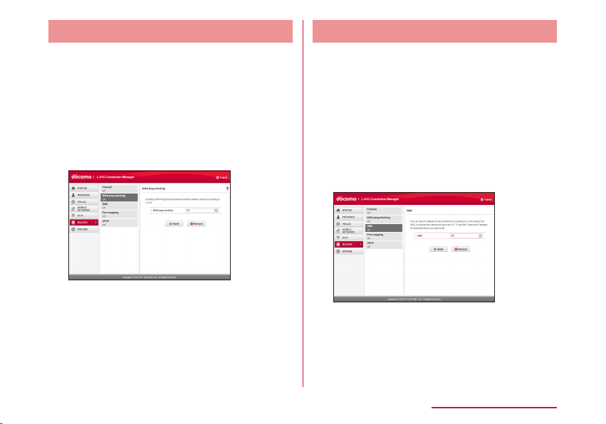
Abandoning Ping from WAN Side
It prevents IP information leak of both this
terminal and the terminal of LAN side by
abandoning Ping request access from WAN
side and not answering.
Click "ROUTER" of the top menu
a
Click "WAN ping blocking" of the sub
b
menu
Set up each item in setting screen
c
WAN ping blocking
Set this function to valid or not.
• On: Set WAN ping blocking function to
valid.
• O: Set WAN ping blocking function to
invalid.
Click "Apply" to save the settings
d
Setting DMZ
One of the devices connected to network on
this terminal can be set to DMZ.
The packet sent from the Internet side to the
device you set is relayed.
When using DMZ, specify an IP address of the
network device to connect.
Click "ROUTER" of the top menu
a
Click "DMZ" of the sub menu
b
Set up each item in setting screen
c
DMZ
• On: Set DMZ to valid and enter an IP
address (0.0.0.1 to 255.255.255.255) of
the network device to connect.
• O
Click "Apply" to save the settings
d
Settings (Web browser)
93
Page 96

Setting Port mapping
Set to allow (port convert) about the
communication starts from the Internet.
Click "ROUTER" of the top menu
a
Click "Port mapping" of the sub menu
b
Set up each item in setting screen
c
Port mapping
• On: Set Port mapping to valid.
• O
Settings (Web browser)
94
■ When setting
Click "Add".
Forward the connection request from "From"
automatically to the certain terminal (IP address
and port number) of "To".
From
• IP address: The IP address on the Internet
side connected to this terminal is displayed.
(This IP address cannot be changed.)
• Port number
Select protocol and enter the port number you
use.
• TCP
• UDP
To
• IP address: Specify an IP address of the client
connected to this terminal.
• Port number: Protocol is set automatically.
Enter the port number of the forward
destination.
When setting, click "Save"
d
Click "Apply" to save the settings
e
Page 97

VPN connection
This terminal provides VPN pass-through
function.
VPN pass-through function allows the client
connected to this terminal supports connection
via external VPN.
PPTP, L2TP and IPsec are VPN protocol
supported by this terminal.
Also, this terminal provides VPN multiple passthrough (to multi clients at the same time is
supported by VPN pass-through)
• The client number for VPN multiple pass-through
does not have a limit.
.
Setting UPnP Function
When using application, etc. which uses UPnP
function, set UPnP function to "On".
Click "ROUTER" of the top menu
a
Click "UPnP" of the sub menu
b
Set up each item in setting screen
c
UPnP
Select whether to use UPnP function.
• On
• O
Click "Apply" to save the settings
d
Settings (Web browser)
95
Page 98

Managing System
Protecting this Terminal by
Password
Set up this function to lock network
communication and the password (PIN1 code)
is required to enter when powering on this
terminal.
Click "SYSTEM" of the top menu
a
Click "PIN1 lock" of the sub menu
b
Set up each item in setting screen
c
Settings (Web browser)
96
PIN1 lock status
The current setting status is displayed.
• Locked: PIN1 lock is set
• Unlocked: PIN1 is unlocked
PIN1 code to set lock/PIN1 code to set
unlock
When changing lock valid/invalid (PIN1 code
input valid/invalid), enter the PIN1 code of
docomo mini UIM card.
Remaining times
The number of available input times of PIN1
code is displayed. (→P34)
Click "Apply" to save the settings
d
Page 99

Unlocking PIN1
If you enter an incorrect PIN1 code three times
in a row, it will be locked and you cannot use it
anymore. In that case, enter "PIN Unlock code"
(→P34) and unlock.
Enter PIN Unlock code in "PIN Unlock
a
code" eld
Enter a new PIN1 code in "New PIN1
b
code" eld
Enter the same PIN1 code as you
c
entered in "New PIN1 code" in
"Conrm PIN1 code" eld to conrm
Click "Apply" to save the settings
d
Changing Password
Password (PIN1 code) can be changed.
• Password (PIN1 code) can only be changed
when PIN1 lock (→P96) is set to "Locked".
Click "SYSTEM" of the top menu
a
Click "PIN1 lock" of the sub menu
b
and click "Modify"
Set up each item in setting screen
c
Current PIN1 code
Enter the PIN1 code set in docomo mini UIM
card.
New PIN1 code
Enter a new PIN1 code.
Settings (Web browser)
97
Page 100

Conrm PIN1 code
Enter the same PIN1 code as you entered in
"New PIN1 code" to conrm.
Remaining times
The number of available input times of PIN1
code is displayed. (→P34)
Click "Save" to save the settings
d
PIN1 code is changed.
Set up each item in setting screen
c
Changing Login Password
The login password of the setting page can
be changed. Set password using 4 to 32-digit
single byte alphanumeric characters, symbol
(~!@#$%^&*-_:,./;|()<>{}[]+=`"'?\) and single byte
space.
Click "SYSTEM" of the top menu
a
Click "Modify password" of the sub
b
menu
Settings (Web browser)
98
Current password
Enter the password you set currently.
New password
Enter a new one.
Conrm password
Enter the same password as you entered in
"New password" to conrm.
Click "Apply"
d
"Password is changed successfully." is
displayed.
Click "OK"
e
 Loading...