

Page 1
Manual
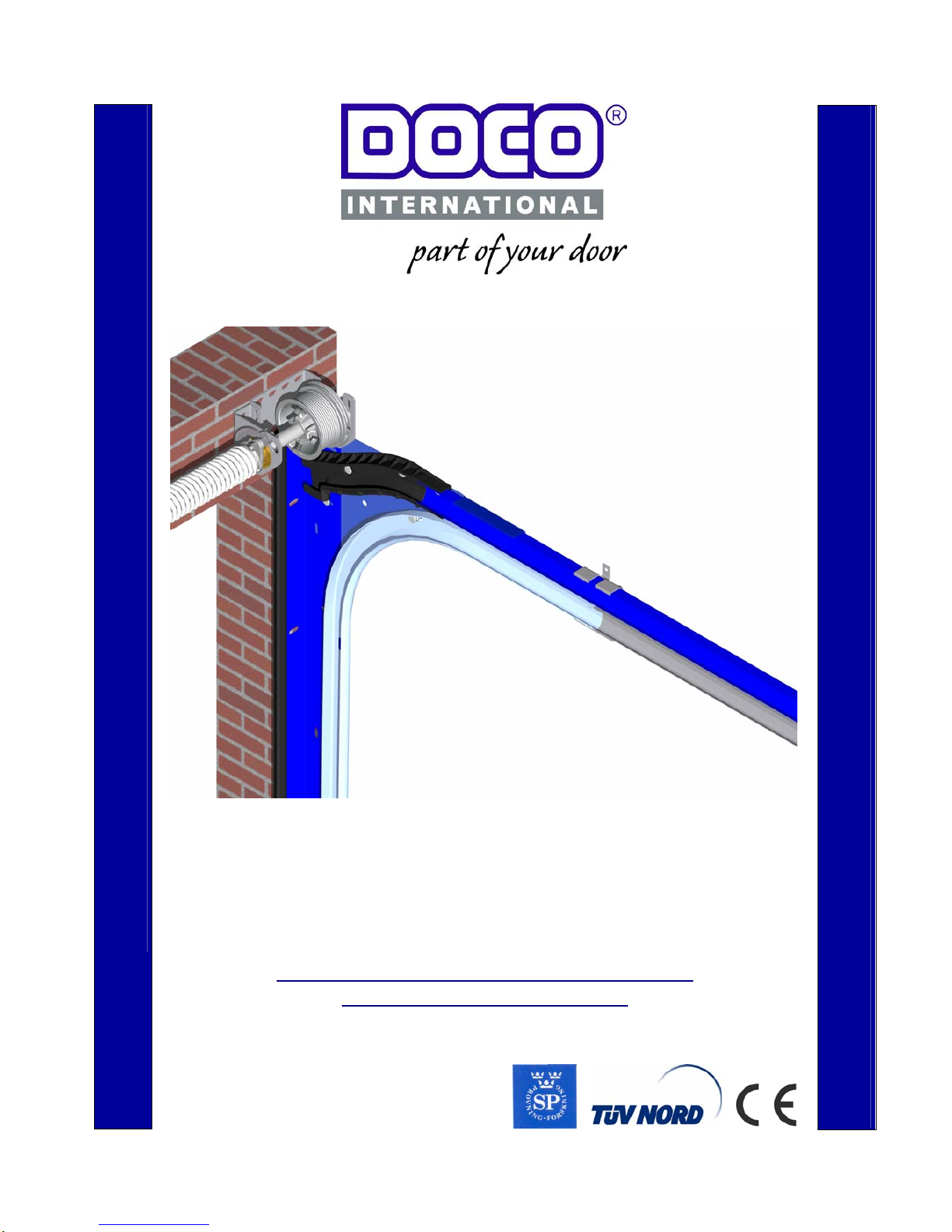
Sectional door with front springs (RES STF)
Conform TÜV / CE EN 13241-1
©All rights reserved.
DOCO International BV
2006
EN
Page 2

8-8-2006
Handleiding
EN STF V1.0 www.doco-international.com
2
Contents
1 Symbols and warning signs 3
2 General warnings 3
2.1 Safety instructions for assembly, commissioning and maintenance 3
2.2 Warranty and liability 3
3 Directives, applications and limitations 4
4 Assembly 5
4.1 Preparing the assembly 5
4.2 Mounting materials and instructions 6
4.3 Tools 6
4.4 Torques 7
4.5 Assembly instructions 8
5 Electric operation (optional) 23
5.1 Adjusting the drive 23
6 Commissioning 23
7 Troubleshooting 23
8 Disassembly 24
8.1 Removal 24
9 Your supplier 24
Annex A Overview hardware and panel combination 25
Annex B Operators 25
Annex C Kits 26
Annex D Assembled galvanised spring sets 31
Annex E Panel hardware 32
Page 3
8-8-2006
Handleiding
EN STF V1.0 www.doco-international.com
3
1. Symbols and warning signs
General symbol for DANGER!!
Symbol for ATTENTION!!
Carefully read the text with this symbol!!
Symbol: Risk of physical injury!!
Carefully read the text with this symbol!!
Use safety gloves Use Face protection
2. General warnings
This manual has been prepared for use by qualifie d pe rso n nel and therefore not by
trainees or “do it yourselfers”
In case of doubt about the assembly and/or maintenance, please contact DOCO
International.
To avoid severe personal injury, carefully read and observe all indications and warnings in this manual.
- This manual describes the assembly and disassembly of residential set of fittings ST ; this may be
supplemented by other manuals, for instance the door operator manual (if applicable.)
- Your set of fittings has been designed according to the latest European standards; however you have to
check yourself whether this standard corresponds with the local national standard.
- Adding or leaving out parts can affect the working and therefore the safety of the eventual sectional
door and is therefore strongly discouraged!
- All indications concerning the assembly the mounting right / left are always viewed from the assembly
location, that is from the inside to the outside!
- All measures are in millimetres unless otherwise specified.
- Check after the assembly whether the CE marking has been completed and attached.
- Keep this manual in a safe place.
- Subject to technical changes, without written notice.
2.1 Safety requirements for assembly and first use.
- The garage door may only be mounted, connected and put into operation by qualified personnel.
- Make sure that the power is switched off and remains switched off while electrical work is carried out!
- Never bridge safety devices !
- Some parts contain sharp edges: use protective gloves.
- Never use the sectional door in case or visual damage on the safety devices.
- When performing assembly/maintenance, always wear at least gloves and safety boots and during
drilling wear safety goggles!
- Make sure that you can always perform your work in a stable environment.
- Secure the assembly/maintenance site with safety ribbon to keep others (children!) at a distance.
- Maintenance must only be performed by a qualified company and/or qualified personnel.
- Make sure there is enough light.
- Only use appropriate tools, especially when tensioning the torsion springs.
Page 4
8-8-2006
Handleiding
EN STF V1.0 www.doco-international.com
4
2.2 Guarantee and liability
Unprofessional assembly, any changes made to the garage door or changes in the door operator that do not
comply with this manual will annul the guarantee and liability.
This also applies to damage caused by incorrect operation, failure to observe the instructions in this manual
and/or poor maintenance or care.
3. Directives, applications and limitations
Doco garage doors comply with the following Directives:
• EMC Directive*
• LVD Directive*
• Machine Directive*
• CPD Directive*
(* E driven doors).
DOCO International developed this hardware set, which is intended for mounting in residential garages:
• Max. width 5000 mm
• Max height 2580 mm
• Weight door panel: max 162 kg
• Noise production: : <70 dBa
• Temperature range: –20º to + 40ºC
• Service-life 25,000 cycles
• CE approved according to SP certificate for use with the correct DOCO parts (see parts lists SET 1 to 4)
DOCO International had the “Product Test“ (ITT Initial Type testing) of this set of fittings carried out by the
institute SP in Sweden, known as Notified Body No. 0402.
Documents of this “ITT” are available from DOCO upon request.
The person or the company installing this door must thoroughly check if the door can be operated safely in
combination with the selected E-drive and panel, see “Product test report (ITT Report)”; Annex A and B.
This “ITT” does NOT include a pass door. If you want to install a pass door, a separate Product Test must be
carried out. This is the responsibility of the garage door manufacturer.
If parts are mounted that are not mentioned or if other parts are used that are not listed in this manual, the CE
certification will be invalid!
Page 5
8-8-2006
Handleiding
EN STF V1.0 www.doco-international.com
5
7 Assembly
This set of fittings does not include the mounting material needed to mount this rail set on walls and/or the
ceiling
! It is the responsibility of the installer to check whether the construction of the mounting place is strong
enough to support this garage door. The installer is also responsible for choosing the appropriate fixing materials
for the foundation (stone, concrete, steel, wood).
4.1. Preparation of the assembly
- Check if the place where you want to mount the rail set is level and if the construction of the mounting
place is strong enough to support this rail set. If not: reinforce
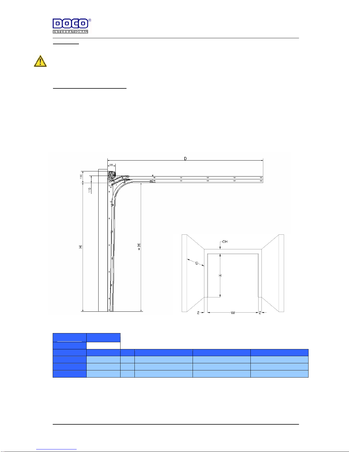
- Before you start the assembly, check if the garage has the required dimensions (figure 1).
W = Clear width
H = Clear height
OH = Upper space
Z = Lateral space
D = Built-in depth
System STF OH = 190
Angle Max Height (H) Z D ( 21182-L / 21226-L) D ( 21226-L / 21270-L) D ( 21270-L / 21340-L)
23699 2140 80 2600 3040 3480
23698 2580 80 3040 3480
Page 6
8-8-2006
Handleiding
EN STF V1.0 www.doco-international.com
6
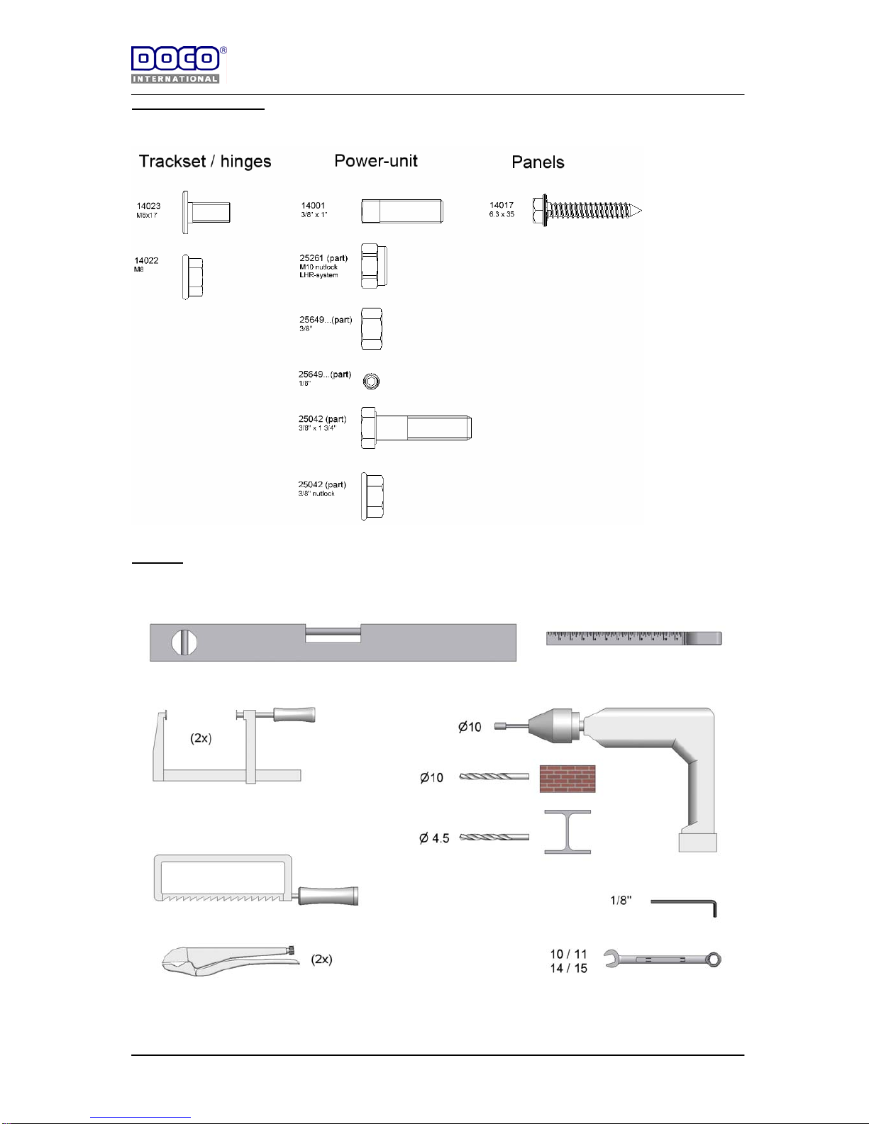
4.2 Mounting materials
4.3 Tools
Page 7
8-8-2006
Handleiding
EN STF V1.0 www.doco-international.com
7
4.4 Toque instructions
Omschrijving Bevestigingsmateriaal Aantal Vastzetmoment (Nm)
Angle (23699/23698) with coverplate (24714) 14022 4x 20
14023 4x 20
Coverplate (24714)) with short horn (22979) 14022 4x 10
14023 4x 10
Curve (22301-L/22251-L) with angle (23699/23698) 14022 20x 20
14023 20x 20
J track (21182-L / 21226-L / 21270-L /21340-L) with connection plate
(24604)
14022 8x 20
14023 8x 20
J track (21182-L / 21226-L / 21270-L /21340-L) with connection plate
(24809)
14022 6x 20
14023 6x 20
J track (21182-L / 21226-L / 21270-L /21340-L) with short horn (22979) 14022 2x 10
14023 2x 10
J trackl (21182-L/21226-L/21270-L) with angle (24621) 14022 2x 20
14023 2x 20
Angle (24621) with mounting plate (24620) 14022 2x 20
14023 2x 20
End bearing plate (13022) and spring break device (25649…) 14022 4x 20
14023 4x 20
End bearing plate (13018 / 13022) and bearing supports (13026/27) 14022 4x 15
14023 4x 15
Spring break device (25649…) and spring plug (12002 S /12003 S) Moer 3/8" 4x 15
Spring break device (25649…) and ratchet wheel (25649….) Inbus 1/8" 4x 4.5
Spring plug (12002 W / 12003 W) and shaft (25018 / 25016) 14001 4x 34
Cable drum ( 11000 /11001 / 11014) and shaft (25018 / 25016) 14001 4x 34
Cable drum (11001 / 11014) and cable (25111-…)
Bolt 3/8"-16UNC-1 1/4"
spec. 2x 18
Coupler (25042) with shaft (25016 /25018) / key (25064 / 25073) 14001 4x 34
Coupler (25042) between the two halves Bolt 3/8"-16UNC-1 3/4" 3 34
Nut nylon 3/8"-16UNC 3 34
Coupler (25034) and shaft (25016 /25018) / key (25064 / 25073) 14001 3x 34
Bottom bracket (25029) and panel 14017 12x 15
Side hinges and panel (per side hinge) 14017 6x 12
Roller carrier and basis side hinge (per hinge) 14022 2x 15
14023 2x 15
Intermediate hinges and panel (per intermediate hinge) 14017 4x 10
Top roller carrier (25046 / 25043) and panel 14017 4x 10
Top roller carrier (25046) and adjustable bracket (25046) 14022 2x 18
14023 2x 18
Page 8
8-8-2006
Handleiding
EN STF V1.0 www.doco-international.com
8
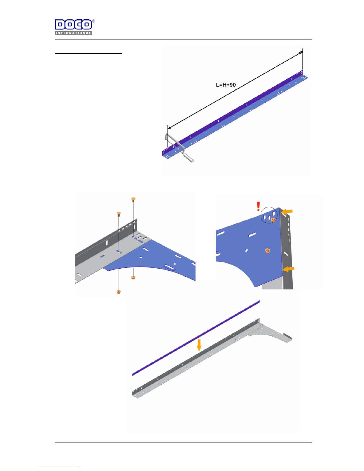
4.5 Assembling instructions
1) Cut the verticale angle
View: right side.
2) Mount the steel cover plate (24714)
View: right side.
3) Mount the weatherstrip (24740)
View: right side.
Page 9
8-8-2006
Handleiding
EN STF V1.0 www.doco-international.com
9
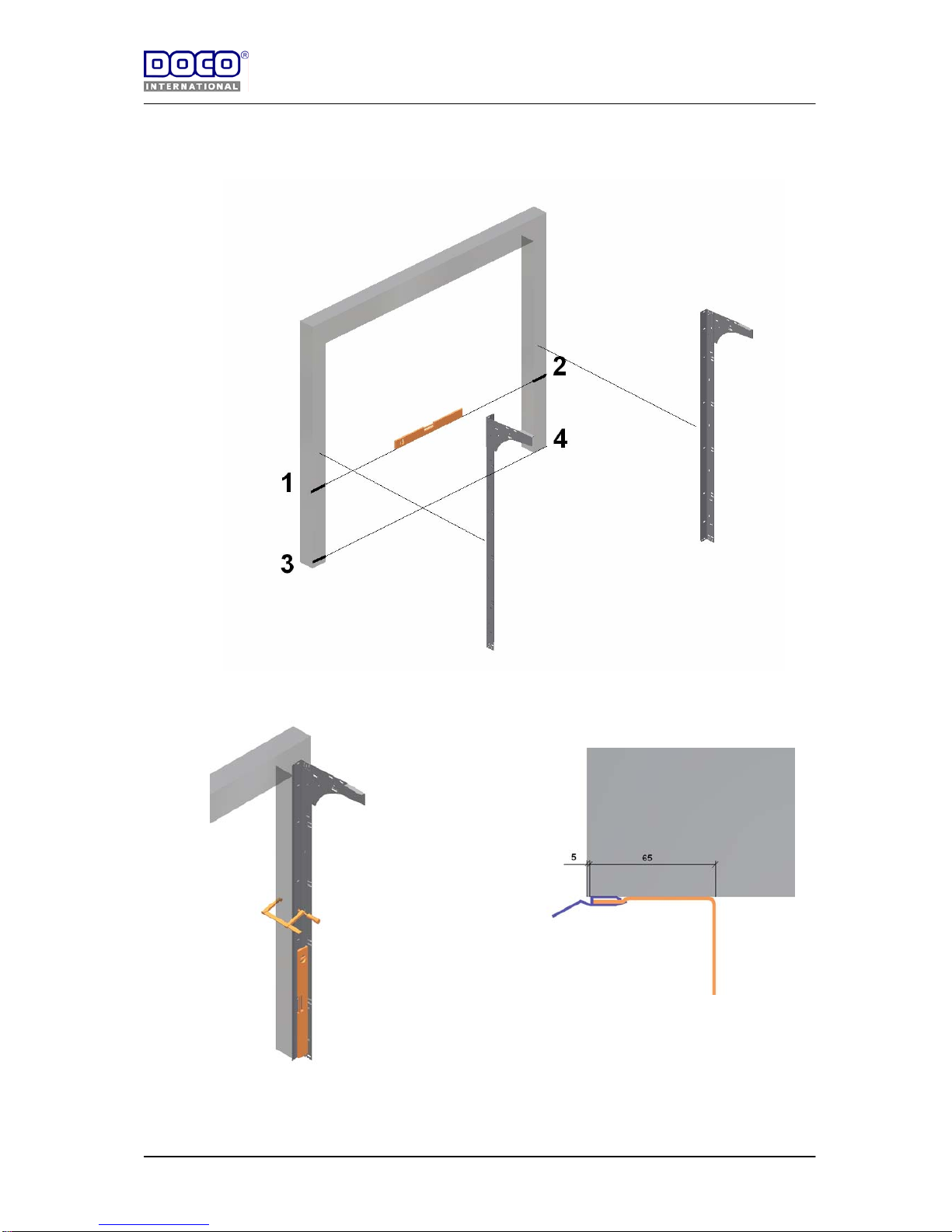
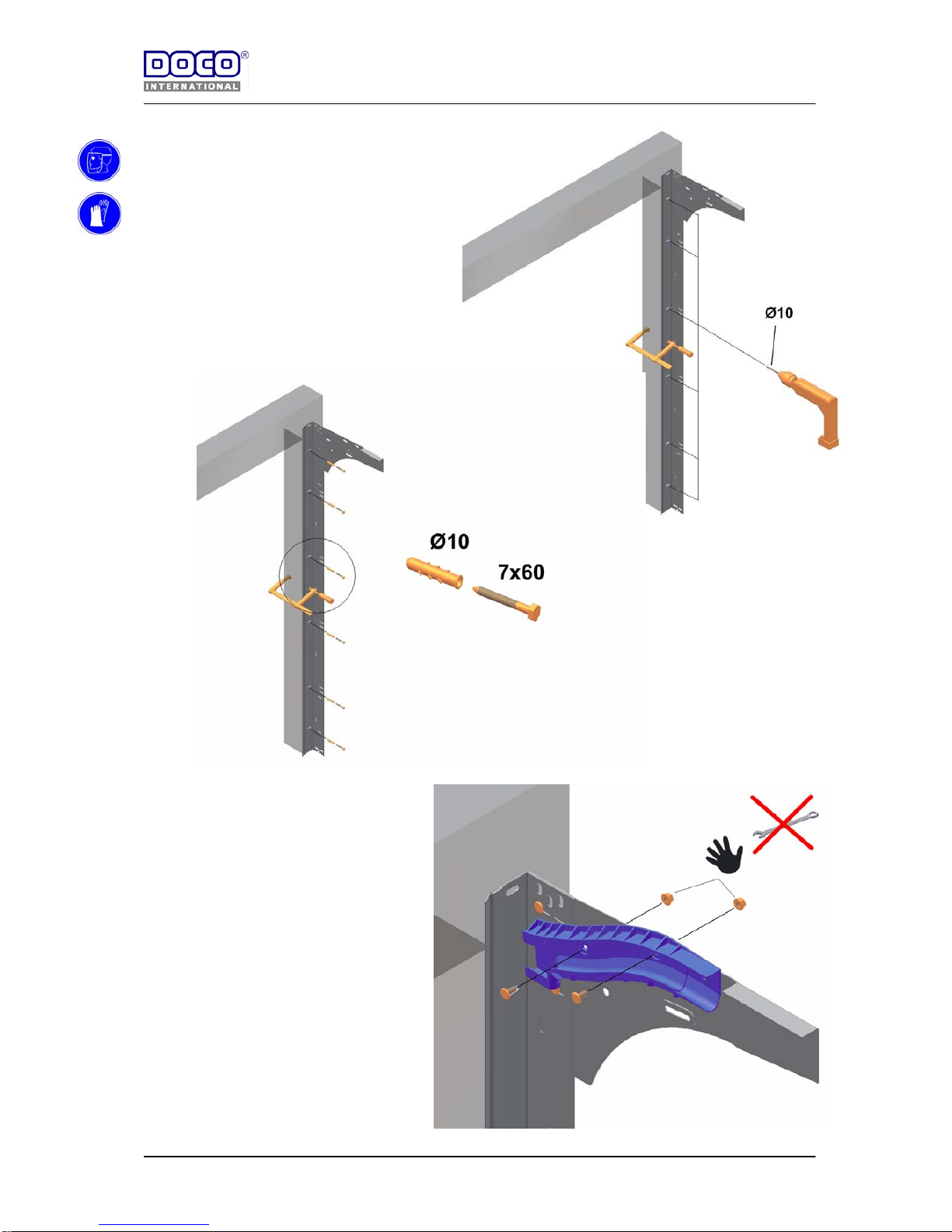
4) Position the vertic al trac ksets
- Floor not level? Fill up at position “3”!
- Height position verticale tracks = underside track, position 4.
5) Mount verticale track part agains the wall.
View: right side
Page 10
8-8-2006
Handleiding
EN STF V1.0 www.doco-international.com
10
6) Mount the short horn, hand fix,
moveable!
View: right side
Page 11
8-8-2006
Handleiding
EN STF V1.0 www.doco-international.com
11
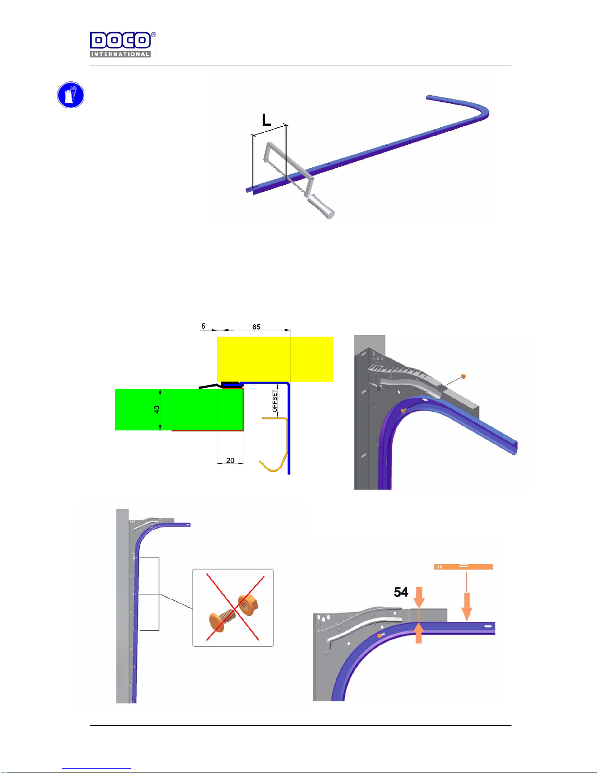
7) Cut the curved track on the right dimension.
Vesion 2140 : L=2140-H+35
Version 2140 till 2580 : L=2580-H+35
View: right side
8) Mount the J track with curve.
Offset 25029 : 38 mm (with 40 mm panel)
Offset 25350 : 36 mm (with 40 mm panel)
View: right side
Page 12
8-8-2006
Handleiding
EN STF V1.0 www.doco-international.com
12
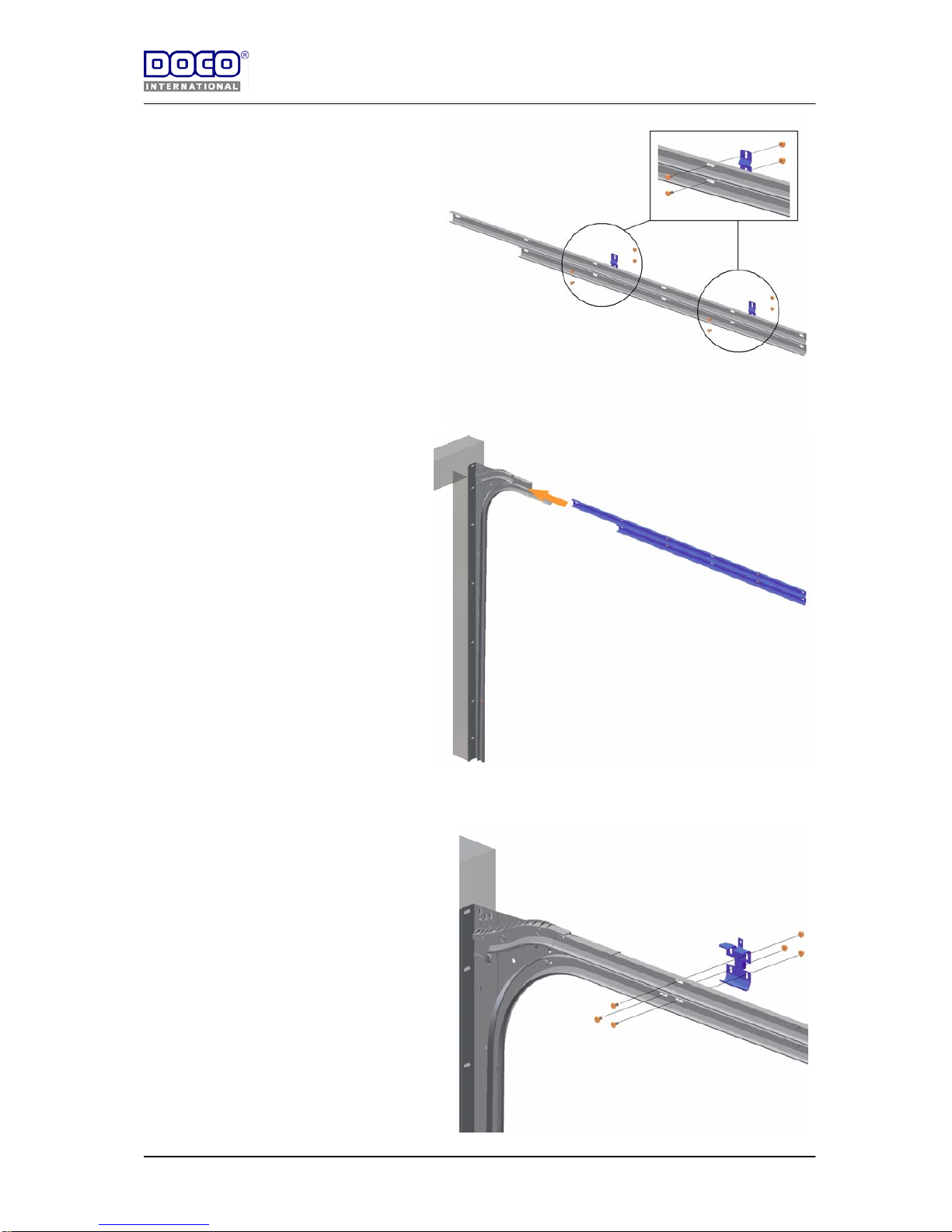
9) Connecting horizontal J track.
View: right side
.
10) Put the connected J track into the verticale trackset part.
View: right side
11) Connect the track with the sleeve.
View: right side
Page 13
8-8-2006
Handleiding
EN STF V1.0 www.doco-international.com
13
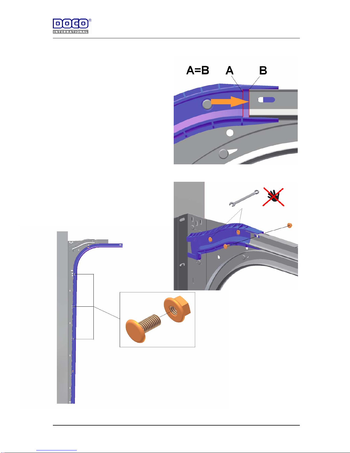
12) Put the short horn against the J track.
View: right side
13) Fasten the short horn with bolts and nuts.
View: right side
Page 14
8-8-2006
Handleiding
EN STF V1.0 www.doco-international.com
14
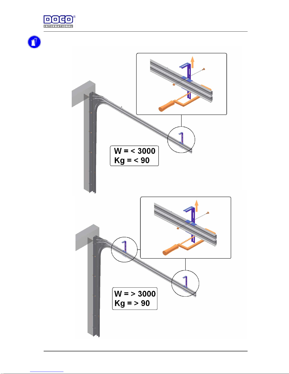
14) Mount the suspension to the roof, to this Left and Richt
View: right side.
Page 15
8-8-2006
Handleiding
EN STF V1.0 www.doco-international.com
15
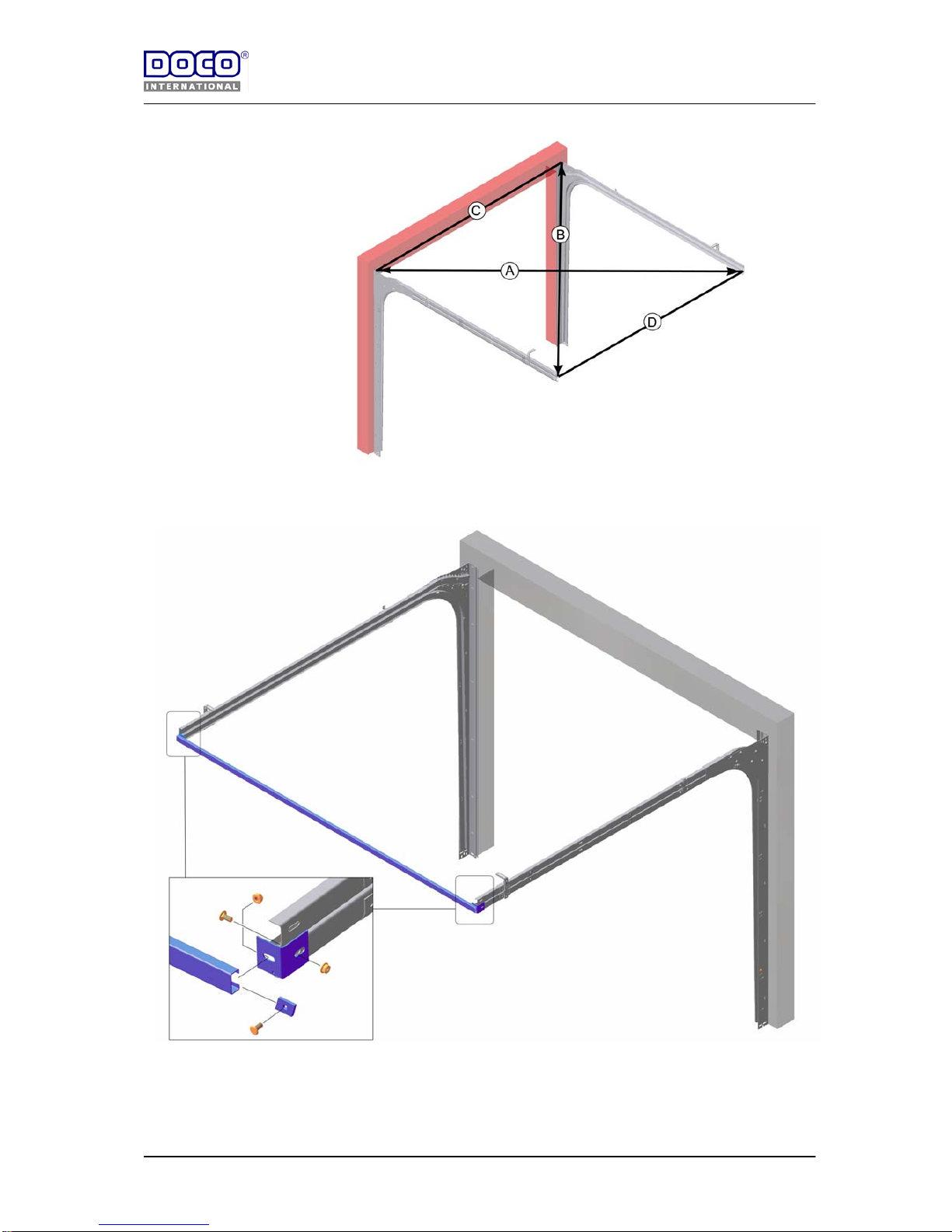
15) Check following:
C=D
A=B
16) Mounting C-track (only if W= >3000 )
Detail: View: right side
Page 16
8-8-2006
Handleiding
EN STF V1.0 www.doco-international.com
16
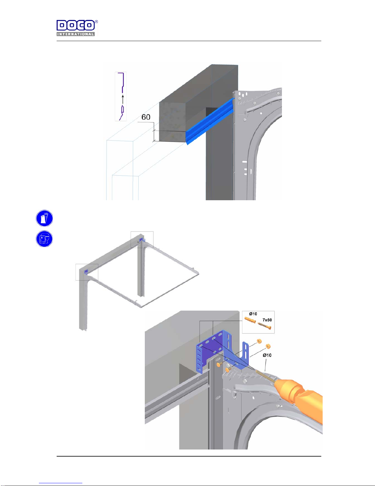
17) Mounting of the lintel sealing:
18) Mounting of the end brackets:
Page 17
8-8-2006
Handleiding
EN STF V1.0 www.doco-international.com
17
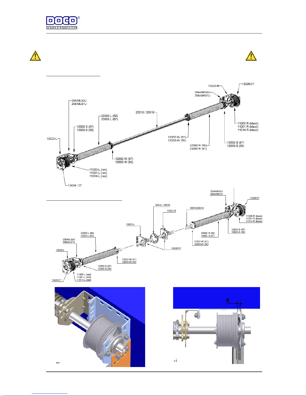
19) Mounting the shaft and springs:
Use : seperate manual residential spring break device (25649-50 / 25649-67)
Doorsize : width < 3000 mm
Doorsize :width > 3000 mm <5000 mm
.
*
Page 18
8-8-2006
Handleiding
EN STF V1.0 www.doco-international.com
18
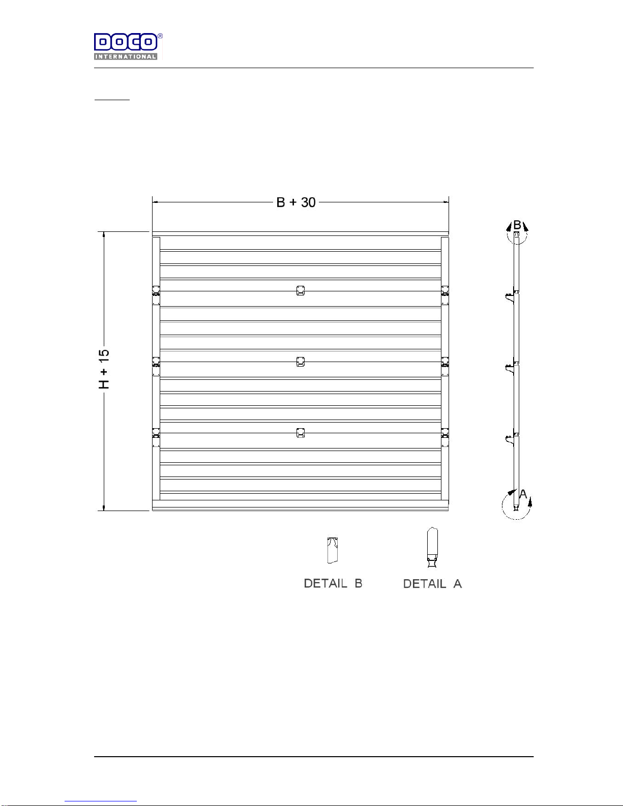
20) Montage van de panelen:
General :
Hereby a general description for mounting the panels.
Always ask the manufacturer of your panel which additional measures, if any, are needed to gu arantee th e fing er
guard Scharnieren voorboren met een Ø 4,5 mm boor ,echter raadpleeg uw paneel fabrikant voor de juist
voorboor maat! Generally, sandwich panels (steel plates with PUR foam) need pre-drilling with Ø 4.5 mm.
However always check with the manufacturer of your panels which exact size you need for pre-drilling!
The entire door blade including aluminium profiles and bottom seal must have the following dimensions.
.
Page 19
8-8-2006
Handleiding
EN STF V1.0 www.doco-international.com
19
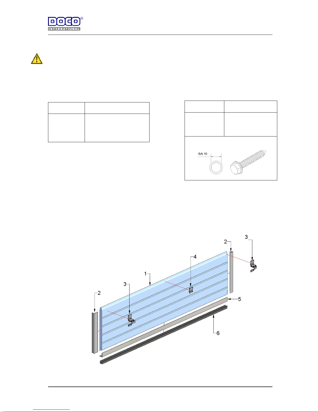
21) Voormontage bodemsectie:
Important: NEVER shorten the bottom panel to
determine the total height of the door blade; always
shorten the top panel!
Consult Annex: A to select the correct hinge and panel combination.
The distance between the central hinges must be distributed evenly over the panel length, see table 1. The
recommended maximum torque of the different parts is listed in table 2.
Tabel 1 Tabel 2
Deurbreedte Aantal middenscharnieren
0-2749
2749-3999
3999-5000
1
2
3
- Saw the panel (1) to the right length.
- Mount the end caps (2) on the panel (1) using
blind rivets.
- Slide the aluminium profile (5) along the
entire length of the panel (1) and secure it
with blind rivets. Slide the sealing rubber on
the aluminium profile.
- Mount the bottom bracket 25029.
- Mount the side and intermediate hinges
Plaat schroef
Art. 14017
Aandraaimoment
Bodenkonsole
Zijscharnier
Middenscharnier
Toprolhouder
12 Nm
12 Nm
10 Nm
12 Nm
Page 20
8-8-2006
Handleiding
EN STF V1.0 www.doco-international.com
20
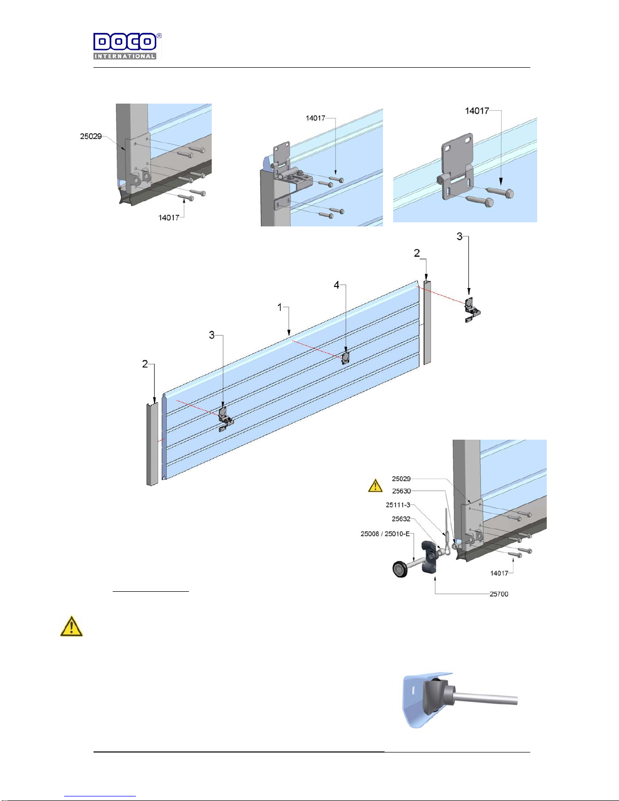
22) Pre-mounting the intermediate sections :
.
23) Placing the panels:
Ensure that you do not forget spacer 25630! Otherwise there is a risk of
damaging the cable set.
- Slide the finger guards (25700) over the track roller body before
mounting the track rollers.
- Place the intermediate sections on the bottom sections and
connect them with the hinges. Adjust the nylon rollers in such a
way that the plastic tread lies in the rounding of the rail and that
the play between panel and side seal (24740) is reduced to a
minimum. You should be able to turn the plastic with your hand.
Page 21
8-8-2006
Handleiding
EN STF V1.0 www.doco-international.com
21
24) Placing the top panel:
- Saw the top panel at the correct height.
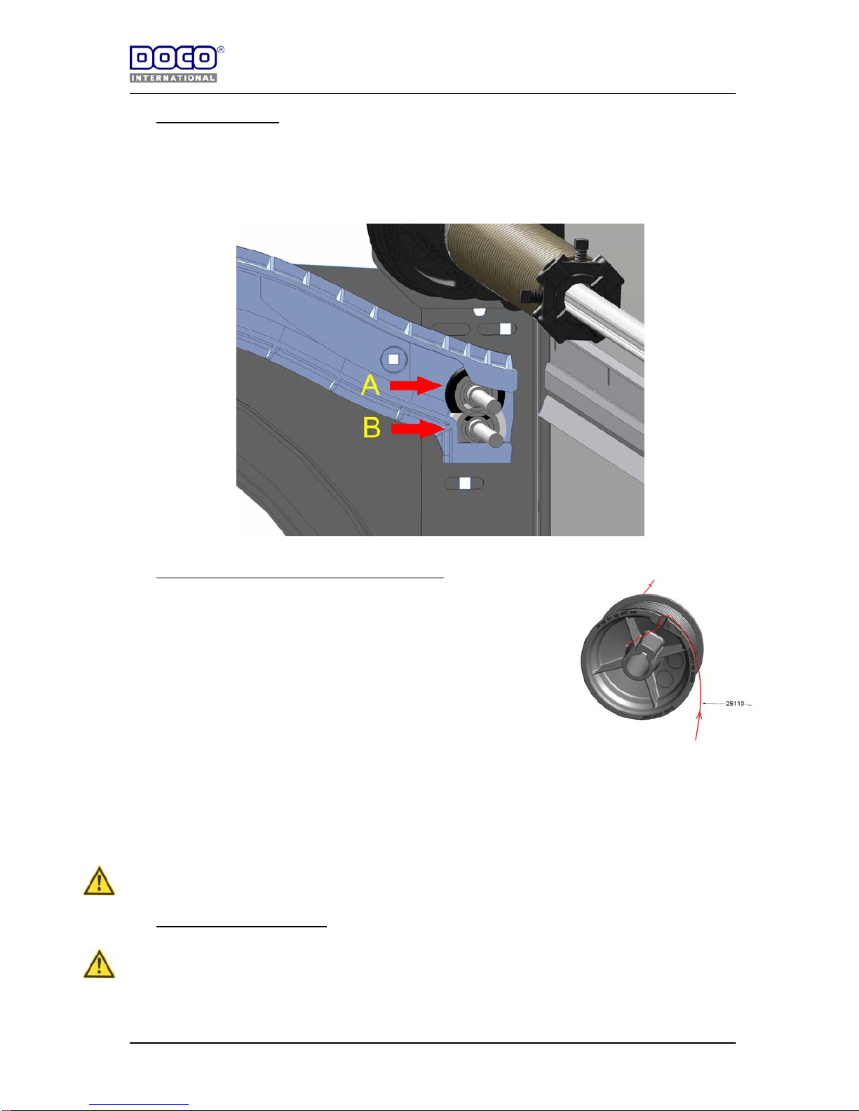
- Do not mount any finger guards (25700) on the top roller!
- The top roller’s mounting to the top roller holder depends on how the door is driven:
POSITION A = E-driven
POSITION B = Hand driven
25) Mounting the cable and positioning the cable drum
- Level the shaft.
- Lead the cable (25111-3) of the bottom bracket (25029) behind the
shafts of the roller to the cable drum (assuming a 11001-11014 cable
drum is being used)
- Slide the cable end through the cable fixing hole of the cable drum
(11001-11014) and turn the cable drum in such a way that the cable
is tensioned and that there is at least cable of ½ a winding** on the
drum; then mount the key (25064-25073) between shaft (25018-
25016) and cable drum (11001 -11014). See figure on the right
** Equals 2 TÜV approved windings // Ref TÜV : BB-FTA-MUC/re-sc
30604_Besch_torque.doc
- Align the cable drum (11001-11014 ) in such a way that it is possible to freely wind up the cable
(25111-..). Secure the cable drum ( 11001-11014 ) with the fixing bo lts on the shaft between 27 –
maximum 34 Nm.
- The cable fixing bolt must be tightened with 13 Nm.
Now block the shaft using the pinchers and secure the other cable the same way.
It is important that both cables are equally tensioned and that the door blade is balanced .
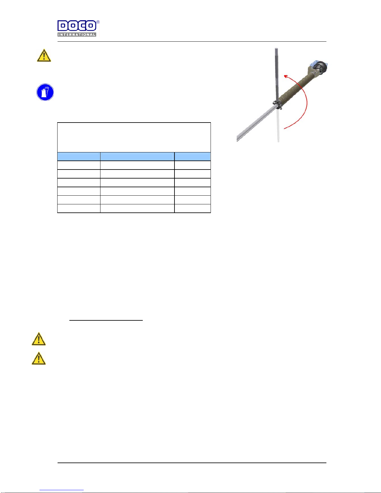
26) Tensioning the torsion springs
Secure the door in such a way that it cannot go up. Fix the vertical tracks for instance with pinch ers .
Tension the springs according to the following procedure.
The required number of turns of the spring is indicated on the labels of the assembled springs.
After tensioning, fix the spring fittings on the shaft with 27 up to 34 Nm (this applies both to spring fitting
12002-W and to spring fitting 12003-W.)
Page 22
8-8-2006
Handleiding
EN STF V1.0 www.doco-international.com
22
IMPORTANT: There is much strain on tensioned springs; proceed
carefully at all times, especially when performing corrective
maintenance, and use tensioning bars that fit well and that are kept
in good condition (12025)
Tension the springs from the bottom to the top! Because of the
stretching the spring becomes thinner and longer (number of turns x
wire thickness); if this is not the case, the left and right spring have
been switched!
Turns spring :
Deur hoogte Kabeltrommel spanslagen
2000 11000 /11001 / 11014 6.9
2125 11000 /11001 / 11014 7.2
2250 11000 /11001 / 11014 7.5
2375 11000 /11001 / 11014 7,9
2500 11000 /11001 / 11014 8.3
1) Mark the spring with a straight line.
2) Insert the first tensioning bar in the tension head.
3) Turn the first tensioning bar a quarter of a turn to stretch the spring.
4) Hold the first tensioning bar and place the second bar in the next hole of the spring fitting.
5) Turn the second a quarter of a turn.
6) Hold the second tensioning bar (takes over the tension) and remove the first bar
7) Repeat steps 3 – 4 – 5 – 6 until the correct tension has been reached.
8) Secure the spring fitting on the shaft by turning both bolts of the fitting with 27 up to 34 Nm.
9) Now remove the second tensioning bar
10) Check the number of turns that the spring has made by counting the number of lines on the spring.
Remove the block of the shaft and the vertical tracks and your sectional door is ready.
Check if the door is well balanced. If not, then check item . (Correction of the spring tension).
27) Correcting the spring tension
Block the shaft and the door blade
Secure the door so that it cannot go up. Do so for instance by fastening pinchers on the ver tical tracks.
IMPORTANT: There is much strain on tensioned springs; proceed carefully at all times, especially when
performing corrective maintenance, and use tensioning bar that fit well and that are kept in good
condition (12025)
You can correct the tension by stretching or releasing the spring with 1 full turn at the most. Make sure that both
springs are equally corrected.
1) Insert the first tensioning bar in the tension head.
2) Turn the tensioning bar in the appropriate direction.
3) Carefully loosen the bolts of the spring fitting and take over the spring tension.
4) Hold the first tensioning bar and place the second bar in the next hole of the spring fitting.
5) Turn the second tensioning bar a quarter of a turn in the desired dir ection.
6) Hold the second tensioning bar (takes over the tension) and remove the first bar
7) Repeat steps 4 - 5 - 6 until the correct tension has been reached.
8) Secure the spring fitting on the shaft by turning both bolts of the spring fitting with 27 up to 34 Nm.
9) Now remove the second bar.
Remove the blocking of the shaft and the vertical tracks and your sectional door is ready.
Page 23
8-8-2006
Handleiding
EN STF V1.0 www.doco-international.com
23
.
28) Finishing the door
Mount the remaining accessories, such as the handle, lock or bolt.
Note: Do not mount any bolts or locks on an E-driven door
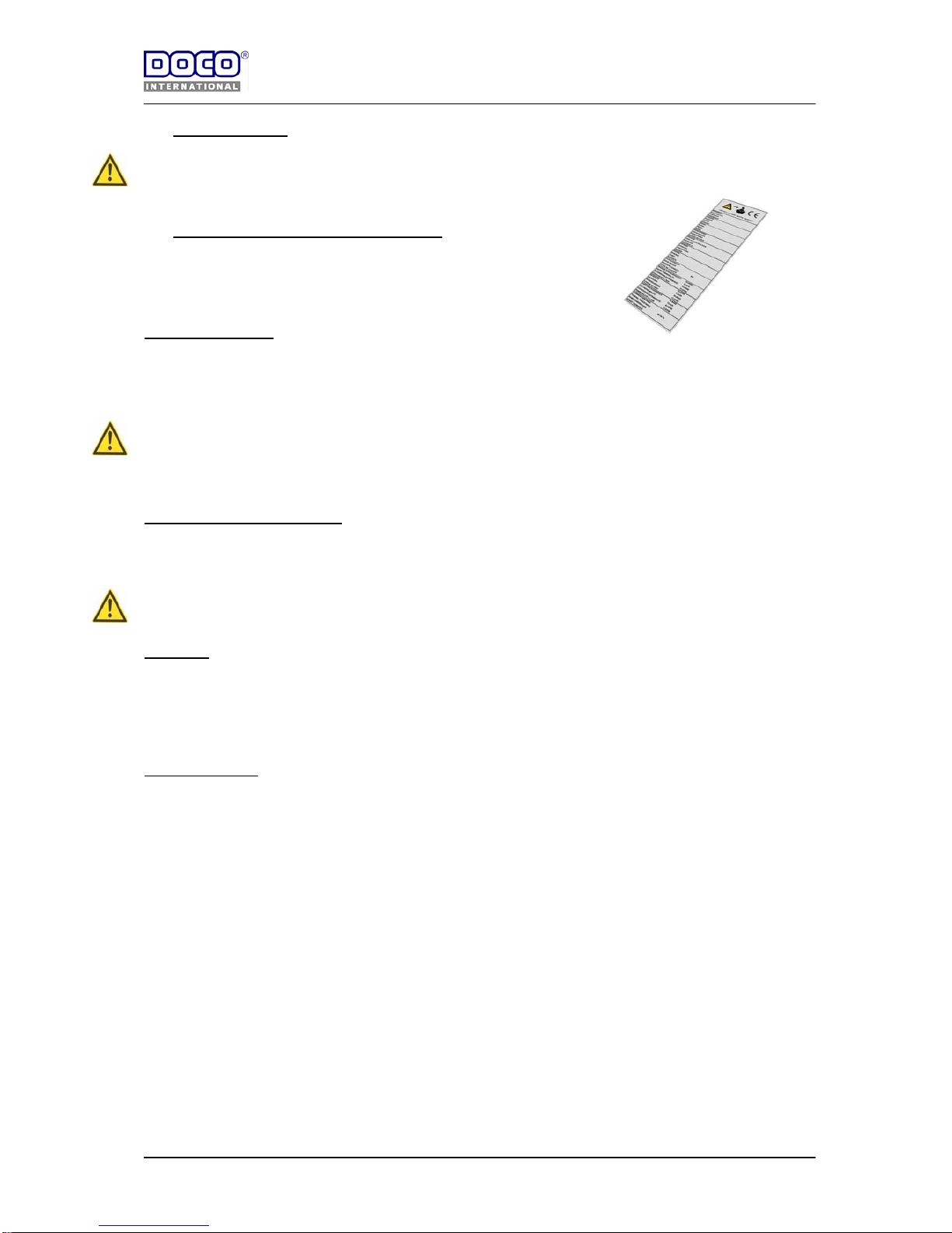
29) Placing the CE-ID plate (sticker)(Obliged)!
Now place the CE sticker (art 80310 NL / FR) on the left or on the right
side under an end cap of the second section.
5 Electrical operator
Mount the operator according to the instructions of it’s’ manufacturer.
Attention!
In case of electrical disconnection one must be able to open the door by an emergency handle. The door can then
be opened or closed manually.
The door may only be operated by a handle.
The handle must be mounted in the centre of the door.
If a second exit in the garage is missing, a disconnecting device must be mounted
5.1 Adjusting the door operator
The door operator must be adjusted according the manual of the door operator.
It is stressed once again that this set of fittings is only TÜV / CE certified in combination with door operators
complying with Annex B. If a different door operator is used, other than the door operators prescribed in
Annex B, the force measurements according to EN 12445/ EN 12453 must be performed again!
6 First use
The garage door must be put into operation by an experienced installer.
The first use of the garage door must be registered. The person responsible for the installation must write the
declaration of conformity and affix the CE sticker.
Affixing the CE-sticker means declaring that the conditions of the EN directives have been met.
7 Trouble Shooter
Points to be checked with a not well functioning/ not balanced door
Check 1) Check the weight of the door
Check 2) Did you receive the right type of drums?
Check 3) Have the cable drums been mounted correctly?
Pay attention to the following (looking from inside to outside)
- Left drum coded red and mounted on the left side?
- Right drum coded black and mounted on the right side?
- Does the cable run between construction/ wall and shaft?
- Check the position of the cable entry
Check 4) Check if the right torsion springs have been delivered and mounted
- Check the wire diameter
- Check the spring diameter
- Check the length of the springs (excluding spring fittings)
Check 5) Door being closed friction must not be too strong. One must be able to still move the rollers.
Check 6) Are there no obstacles while opening/ closing the door?
Check 7) Check the space between doorblade and tracks, which should be around 20 mm and the cable
is not to get stuck at any place.
Check 8) Are the rollers parallel in vertical and horizontal direction? Take measurement of distance and
height.
Page 24
8-8-2006
Handleiding
EN STF V1.0 www.doco-international.com
24
8 Dismounting
General:
- Dismounting may only be carried out by qualified personnel.
- Make sure that only personnel taking care of the mounting/dismounting is present at the mounting
place. Keep other persons at a distance, for example by using a safety ribbon
- When dismounting the device, make sure there is enough light.
- Make sure that you use the right tools to remove the tension of the springs and make sure you are
standing firmly
Procedure:
Block the shaft with the pinchers.
Secure the door in such a way that it cannot come up. Do so for instance by fastening pin c hers to the vertical
tracks.
IMPORTANT: There is much strain on tensioned springs; proceed carefully at all times and use tensioner
bars that fit well and that are kept in good condition (12025)
1) Insert the first tensioning bar in the spring fitting.
2) Keep the first tensioning bar firmly in your hands and carefully loosen the bolts on the spring fitting and
take over the spring tension.
3) Now place the second tensioning bar in the next hole of the sping fitting and carefully release the
spring. The spring is basically released from top to bottom.
4) Put the first tensioning bar back in the spring fitting and release.
5) Repeat steps 3 - 4 until the spring is released.
6) Repeat steps 1 - 4 with the other spring.
7) Loosen the bolts of the cable drums and remove the steel cables from the cable drums.
8) Dismount the shaft with springs
9) Loosen the bolts and nuts from the coupling of the synthetic curve with horizontal track.
10) Dismount the suspension and slide the horizontal track out of the plastic curve.
11) Dismount the panel sections from top to bottom by loosening the roller carriers and intermediate
hinges.
12) Dismount the synthetic curve.
13) Dismount the vertical angle.
8.1 Removal
All parts of the garage door are easy to separate and to recycle.
Separate all elements after dismantling.
Note: The material is only recyclable if separated
Turn in the materials at the authority responsible for the treatment of separated materials.
10 Your Manufacturer
DOCO International b.v.
Nusterweg 96
6136 KV Sittard (NL)
Tel. +31 46-4200666
Fax. +31 46-4526894
E-mail : [email protected]
Page 25
8-8-2006
Handleiding
EN STF V1.0 www.doco-international.com
25
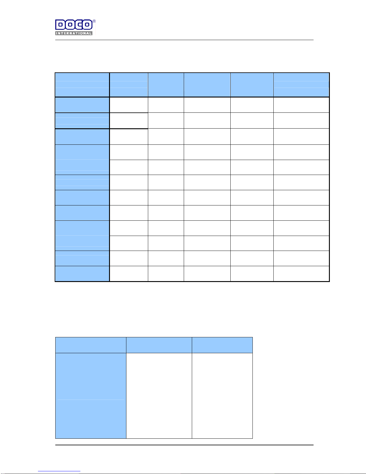
Annex: A Overview hardware with panel combination
Panel (1) Endcap (2)
Side hinge
(3)
Intermediate
hinge (4)
Alu.Profile (5)
Top and
bottom
Bottom seal (6)
Bremet Securwall
80612L (610) /
80617L (488)
25734 25733 80041 80042
Bremet Securwall
80612L (610) /
80617L (488)
25162 /
25163
25733 80041 80042
Hoesch
80612L (610) /
80613L (488)
25334 25333 80041 80042
Hoesch
80612L (610) /
80613L (488)
25162 /
25164
25333 80041 80042
Tekla Teckentrup
118438 /
118449
109555 /
122292
109554 116261 109549
Apco - Kingspann
80612L (610) /
80617L (488)
25334 25333 80041 80042
Ryterna
80612L (610) /
80617L (488)
25634 25633 80041 80042
Annex B Certified operators
Operator :
Type :
Max. door width
Sommer
Sommer
Sommer
Sommer
Marantec
Marantec
Aperto 868 L(550N)
Aperto 868 LX(800N)
Duo 500S (500N)
Duo 800SL (800N)
Comfort 220 (500N)
Comfort 250 (700N)
3500 mm
5000 mm
3000 mm
5000 mm
3500 mm
5000 mm
Page 26
8-8-2006
Handleiding
EN STF V1.0 www.doco-international.com
26
Annex C: Kits (5 pages)
Page 27
8-8-2006
Handleiding
EN STF V1.0 www.doco-international.com
27
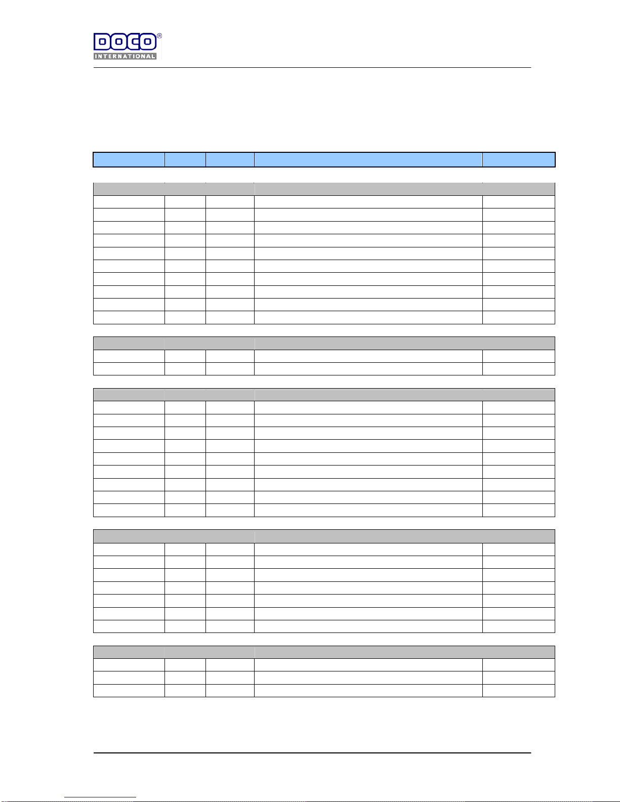
STF SET 1
WxH [mm] : ≤3000 x ≤2140
Art.nr. Pieces Amount Description Cutting
Trackset with seals
23699 2 St. Vertical angle, L=2230 mm (1xleft + 1xright) H+90
21182-L 2 St. Track, L=1820 mm short horizontal
21226-L 2 St. Track, L=2260 mm long horizontal
24714 1 Pr. Steel plate 2 mm
22251-L 1 Pr. Curved track 90,5° Lcut=2140-H+35
22979 1 Pr. Plastic short horn
24604 4 St. Track connection plate
24744 1 St. Weather strip, L = 4500 mm (vertical 2x) H+50
24741 1 St. Weather strip, L = 3500 mm (horizontal) W
24710 1 St. Installation profile, L = 5500 mm W-20
Suspension
24807 2 St. Roof hangar
24809 4 St. Sleeve for installation bracket
Power-unit
11014 1 Pr. Cable-drums
13022 1 Pr. Mounting bracket
13026/27 2 St. Bearing with container.
25649L50-U 1 St. Residential spring failure device, Left Type 50 mm
25649R50-U 1 St. Residential spring failure device, Right Type 50 mm
25019-32 1 St. Tubular shaft, L=3200 mm. W+220
30xxx 1 Pr. Assembled galvanised springs: see page 30
25110-3 1 Pr. Aircraft cable assembled, 3 mm, L=3000 mm
25073 4 St. Bended key for tubular shaft
Panel components
25029 1 Pr. Bottom corner bracket
25632 2 St. Spacers for rollers, 10 mm
25631 2 St. Spacers for rollers, 7,5 mm
25630 2 St. Spacers for rollers, 5 mm
25403 1 St. PVC pull handle
80041 1 St. Aluminium profile lg=5600 (1xbottom , 1x top) W+30
80042 1 St EPDM bottom seal W+30
Fasteners
14017 78 St. Self tapping fastener
14022 66 St. Nuts for track bolts M8
14023 66 St. Track bolts M8
Page 28
8-8-2006
Handleiding
EN STF V1.0 www.doco-international.com
28
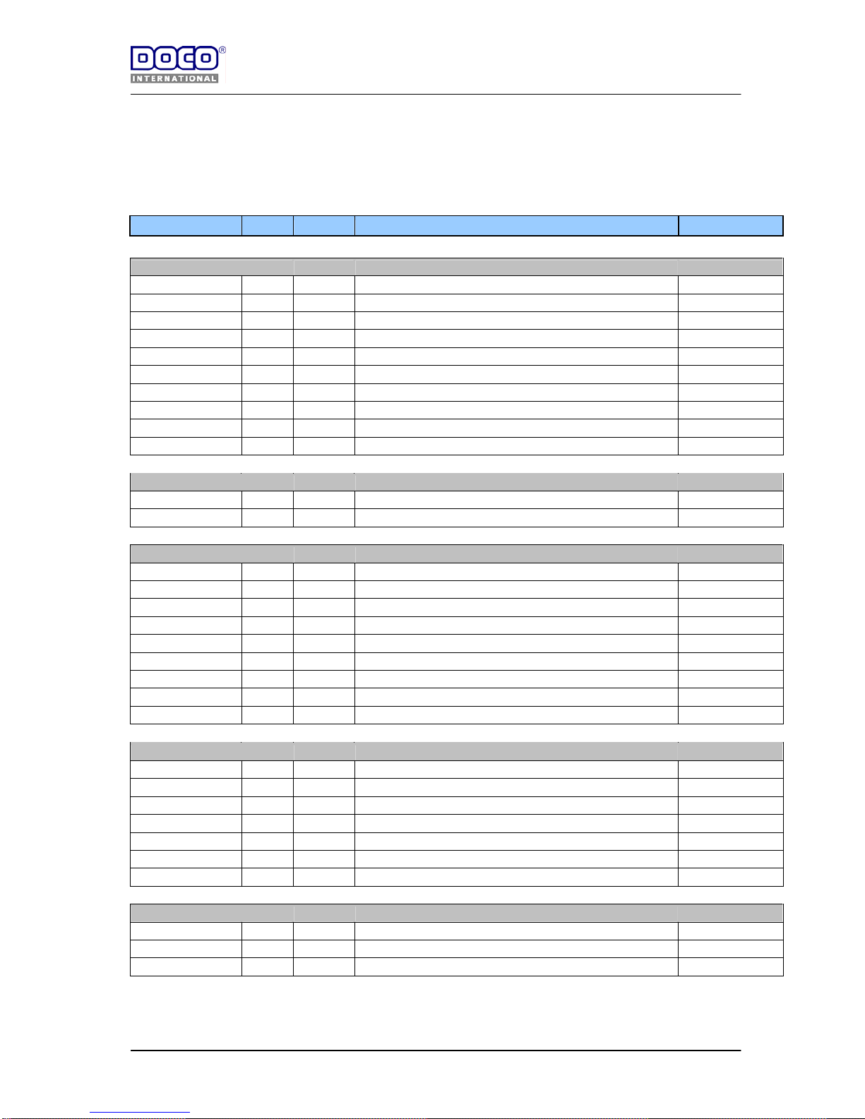
STF SET 2
WxH [mm] : ≤3000 x ≥2140≤2580
Art.nr. Pieces Amount Description Cutting
Trackset with seals
23698 2 St. Vertical angle, L=2670 mm (1xleft + 1xright) H+90
21226-L 2 St. Track, L=2260 mm short horizontal
21270-L 2 St. Track, L=2700 mm long horizontal
24714 1 Pr. Steel plate 2 mm
22301-L 1 Pr. Curved track 90,5° Lcut=2580-H+35
22979 1 Pr. Plastic short horn
24604 4 St. Track connection plate
24740 1 St. Weather strip, L = 6000 mm (vertical 2x) H+50
24741 1 St. Weather strip, L = 3500 mm (horizontal) W
24710 1 St. Installation profile, L = 5500 mm W-20
Suspension
24807 4 St. Roof hangar
24809 4 St. Sleeve for installation bracket
Power-unit
11014 1 Pr. Cable-drums
13022 1 Pr. Mounting bracket
13026/27 2 St. Bearing with container.
25649L50/67 U 1 St. Residential spring failure device, Left Type 50/67 mm
25649R50/67 U 1 St. Residential spring failure device, Right Type 50/67 mm
25018-35 1 St. Tubular shaft, L=3500 mm. W+220
30xxx 1 Pr. Assembled galvanised springs: see page 30
25110-3 1 Pr. Aircraft cable assembled, 3 mm, L=3000 mm
25073 4 St. Bended key for tubular shaft
Panel components
25029 1 Pr. Bottom corner bracket
25632 2 St. Spacers for rollers, 10 mm
25631 2 St. Spacers for rollers, 7,5 mm
25630 2 St. Spacers for rollers, 5 mm
25403 1 St. PVC pull handle
80041 1 St. Aluminium profile lg=5600 (1xbottom , 1x top) W+30
80042 1 St EPDM bottom seal W+30
Fasteners
14017 94 St. Self tapping fastener
14022 66 St. Nuts for track bolts M8
14023 66 St. Track bolts M8
Page 29
8-8-2006
Handleiding
EN STF V1.0 www.doco-international.com
29
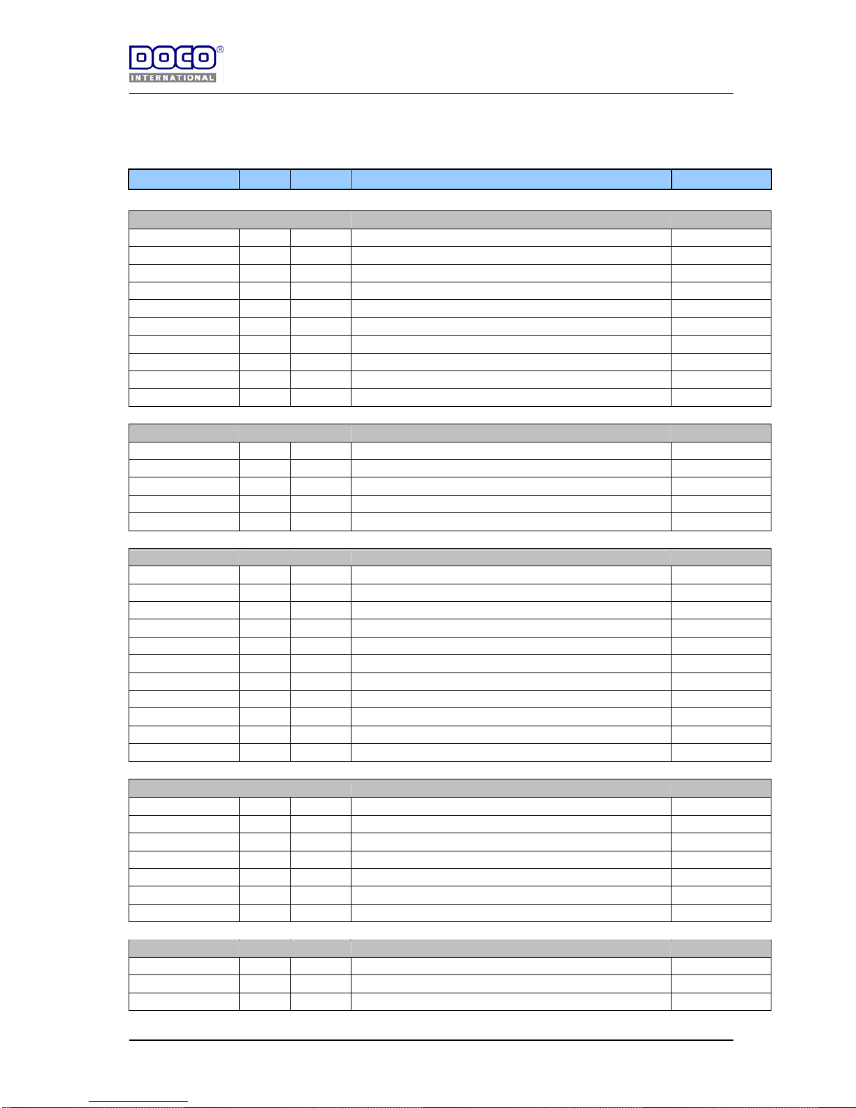
STF SET 3
WxH [mm] : ≤3000≤5000 x ≤2140
Art.nr. Pieces Amount Description Cutting
Trackset with seals
23699 2 St. Vertical angle, L=2230 mm (1xleft + 1xright) H+90
21182-L 2 St. Track, L=1820 mm short horizontal
21226-L 2 St. Track, L=2260 mm long horizontal
24714 1 Pr. Steel plate 2 mm
22251-L 1 Pr. Curved track 90,5° Lcut=2140-H+35
22979 1 Pr. Plastic short horn
24604 4 St. Track connection plate
24744 1 St. Weather strip, L = 4500 mm (vertical 2x) H+50
24745 1 St. Weather strip, L = 5000 mm (horizontal) W
24710 1 St. Installation profile, L = 5500 mm W-20
Suspension
24807 4 St. Roof hangar
24809 4 St. Sleeve for installation bracket
24621 2 St. Mounting angle
24854 1 St. C-profile L=5400 mm W+130
24620 2 St. Lock plates
Power-unit
11014 1 Pr. Cable-drums
13022 1 Pr. Mounting bracket
13026/27 4 St. Bearing with container.
25649L50/67-U 1 St. Residential spring failure device, Left Type 50/67 mm
25649R50/67-U 1 St. Residential spring failure device, Right Type 50/67 mm
25018-60 1 St. Tubular shaft, L=6000 mm. W+220
30xxx 1 Pr. Assembled galvanised springs: see page 30
25110-3 1 Pr. Aircraft cable assembled, 3 mm, L=3000 mm
25073 4 St. Bended key for tubular shaft
13023 1 Pr. Mounting Bracket
25042 1 St. Coupler
Panel components
25029 1 Pr. Bottom corner bracket
25632 2 St. Spacers for rollers, 10 mm
25631 2 St. Spacers for rollers, 7,5 mm
25630 2 St. Spacers for rollers, 5 mm
25403 1 St. PVC pull handle
80041 2 St. Aluminium profile lg=5600 (1xbottom , 1x top) W+30
80042 1 St EPDM bottom seal W+30
Fasteners
14017 120 St. Self tapping fastener
14022 72 St. Nuts for track bolts M8
14023 72 St. Track bolts M8
Page 30
8-8-2006
Handleiding
EN STF V1.0 www.doco-international.com
30
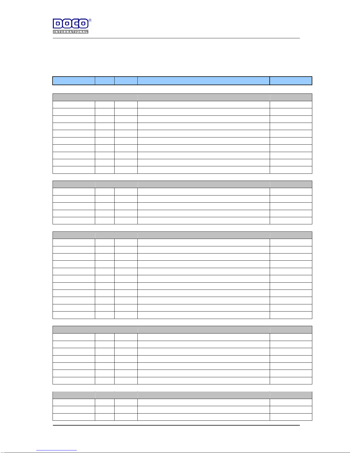
STF SET 4
WxH [mm] : ≤3000≤5000 x ≥2140≤2580
Art.nr. Pieces Amount Description Cutting
Trackset with seals
23698 2 St. Vertical angle, L=2670 mm (1xleft + 1xright) H+90
21226-L 2 St. Track, L=2260 mm short horizontal
21270-L 2 St. Track, L=2700 mm long horizontal
24714 1 Pr. Steel plate 2 mm
22301-L 1 Pr. Curved track 90,5° Lcut=2580-H+35
22979 1 Pr. Plastic short horn
24604 4 St. Track connection plate
24740 1 St. Weather strip, L = 6000 mm (vertical 2x) H+50
24745 1 St. Weather strip, L = 5000 mm (horizontal) W
24710 1 St. Installation profile, L = 5500 mm W-20
Suspension
24807 4 St. Roof hangar
24809 4 St. Sleeve for installation bracket
24621 2 St. Mounting angle
24854 1 St. C-profile L=5400 mm W+130
24620 2 St. Lock plates
Power-unit
11014 1 Pr. Cable-drums
13022 1 Pr. Mounting bracket
13026/27 4 St. Bearing with container.
25649L50/67-U 1 St. Residential spring failure device, Left Type 50/67 mm
25649R50/67-U 1 St. Residential spring failure device, Right Type 50/67 mm
25018-60 1 St. Tubular shaft, L=6000 mm. W+220
30xxx 1 Pr. Assembled galvanised springs: see page 30
25110-4 1 Pr. Aircraft cable assembled, 3 mm, L=4000 mm
25073 4 St. Bended key for tubular shaft
13023 1 Pr. Mounting Bracket
25042 1 St. Coupler
Panel components
25029 1 Pr. Bottom corner bracket
25632 2 St. Spacers for rollers, 10 mm
25631 2 St. Spacers for rollers, 7,5 mm
25630 2 St. Spacers for rollers, 5 mm
25403 1 St. PVC pull handle
80041 2 St. Aluminium profile lg=5600 (1xbottom , 1x top) W+30
80042 1 St EPDM bottom seal W+30
Fasteners
14017 120 St. Self tapping fastener
14022 72 St. Nuts for track bolts M8
14023 72 St. Track bolts M8
Page 31
8-8-2006
Handleiding
EN STF V1.0 www.doco-international.com
31
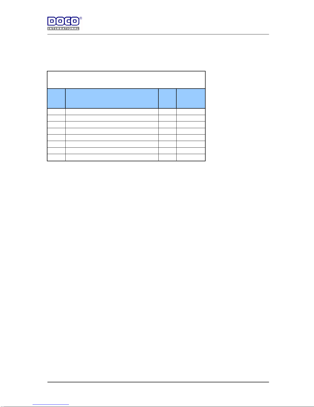
Annex D
SPRING sets* (galvanised pre-installed)
Article Springs couple D x d x lg [mm]
Door
width
[mm]
weight
doorblade
[kg]
30100 L/R 50x5,0x510 2375 59-67
30200 L/R 50x5,5x715 2500 68-73
30300 L/R 50x5,5x680 2500 72-77
30400 L/R 50x5,5x660 3000 74-79
30500 L/R 50x5,5x570 3000 86-92
30600 L/R 67x6,5x710 5000 125-132
30700 L/R 50x7,0x880 5000 142-152
* Remarks :
- Weight are based on usage elec. Operator.
- Only for door height between 2100-2250 mm
- For other door widths or heights use DOCO door processing!
Page 32
8-8-2006
Handleiding
EN STF V1.0 www.doco-international.com
32
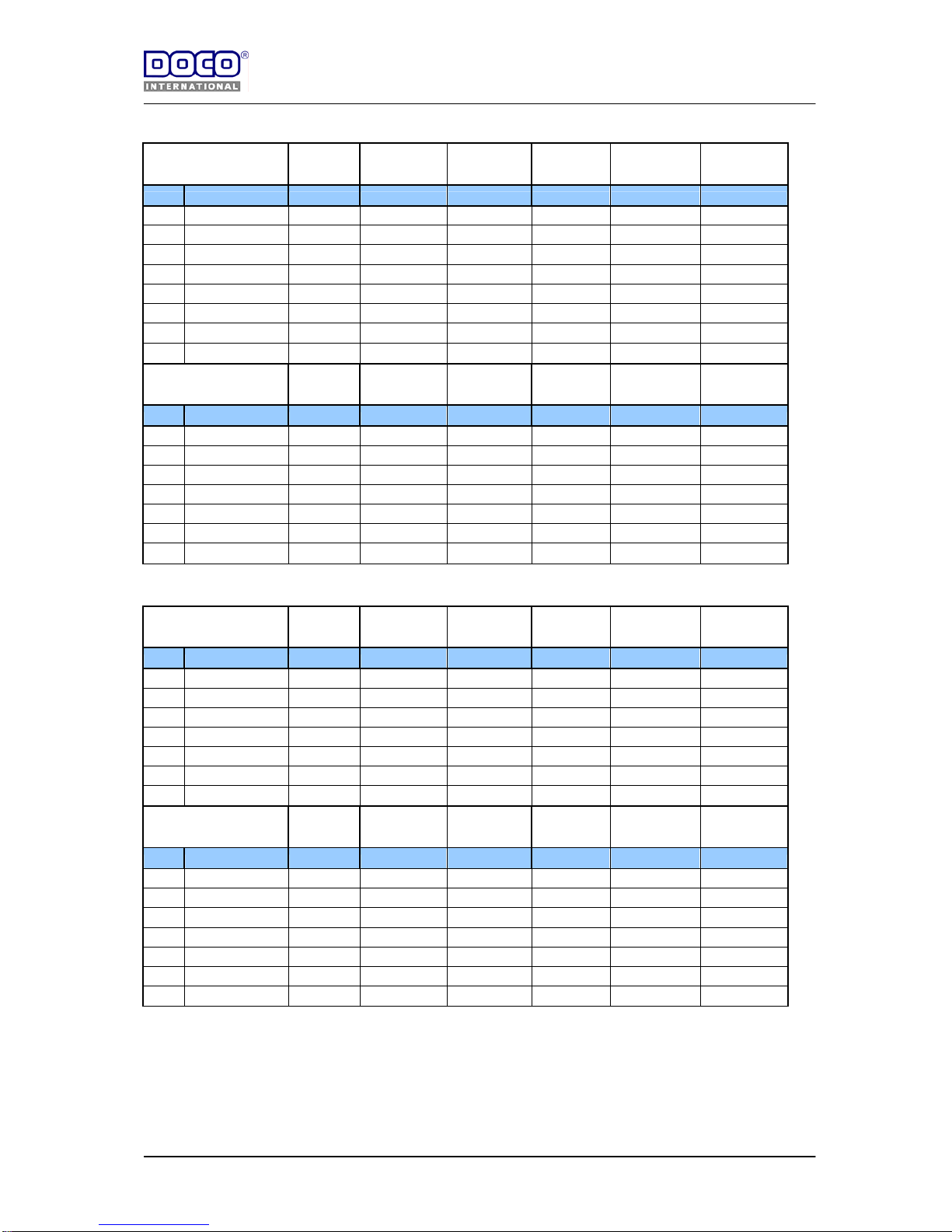
Annex E
Note for end caps :
- Depending of section height and section quantity.
Hardware for
Hoesch panel
W <2749 x
H< 2440
W >2750<3999
x H< 2440
W >3999<5000
x H< 2440
W <2749 x
H>2440<2850
W >2750<3999
x H>2440<2850
W >3999<5000
x H>2440<2850
Article Description Pieces Pieces Pieces Pieces Pieces Pieces
25334 Side hinge 6 6 6 8 8 8
25333 Intermediate hinge 3 6 9 4 8 12
25008 Roller 8 8 8 10 10 10
25043 Top roller carrier 2 2 2 2 2 2
80612L End cap 610 mm see note see note see note see note see note see note
80613L End cap 488 mm see note see note see note see note see note see note
Hardware for
Kingspan panel
W <2749 x
H< 2440
W >2750<3999
x H< 2440
W >3999<5000
x H< 2440
W <2749 x
H>2440<2850
W >2750<3999
x H>2440<2850
W >3999<5000
x H>2440<2850
Article Description Pieces Pieces Pieces Pieces Pieces Pieces
25334 Side hinge 6 6 6 8 8 8
25333 Intermediate hinge 3 6 9 4 8 12
25008 Roller 8 8 8 10 10 10
25043 Top roller carrier 2 2 2 2 2 2
80612L End cap 610 mm see note see note see note see note see note see note
80617L End cap 500 mm see note see note see note see note see note see note
Hardware for
Ryterna panel
W <2749 x
H< 2440
W >2750<3999
x H< 2440
W >3999<5000
x H< 2440
W <2749 x
H>2440<2850
W >2750<3999
x H>2440<2850
W >3999<5000
x H>2440<2850
Article Description Pieces Pieces Pieces Pieces Pieces Pieces
25634 Side hinge 6 6 6 8 8 8
25633 Intermediate hinge 3 6 9 4 8 12
25008 Roller 8 8 8 10 10 10
25043 Top roller carrier 2 2 2 2 2 2
80612L End cap 610 mm see note see note see note see note see note see note
80617L End cap 500 mm see note see note see note see note see note see note
Hardware for
Bremet
p
anel
W <2749 x
H< 2440
W >2750<3999
x H< 2440
W >3999<5000
x H< 2440
W <2749 x
H>2440<2850
W >2750<3999
x H>2440<2850
W >3999<5000
x H>2440<2850
Article Description Pieces Pieces Pieces Pieces Pieces Pieces
25734 Side hinge 6 6 6 8 8 8
25733 Intermediate hinge 3 6 9 4 8 12
25008 Roller 8 8 8 10 10 10
25043 Top roller carrier 2 2 2 2 2 2
80612L End cap 610 mm see note see note see note see note see note see note
80617L End cap 500 mm see note see note see note see note see note see note
 Loading...