

Page 1
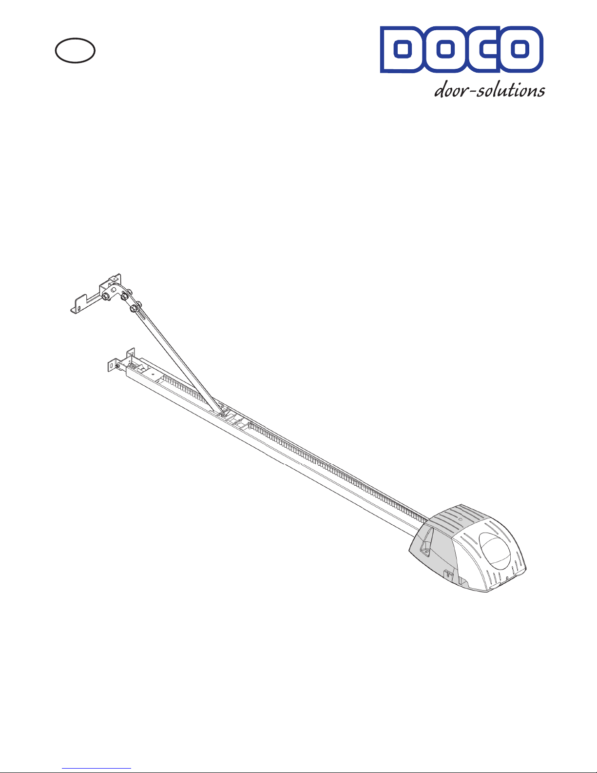
DOCOMATIC 1200
Installation Manual
- With tips on operation and maintenance -
Garage door drives
Art.-Nr. 501003
GB
DOCOMATIC 1/23 04-10
Page 2
1
2
3 4
5 6
8
7
Ø3
Ø10
Ø5
6/10/13/17
a
b
e
c
d
1
2
3
4
Motor
a)
DOCOMATIC 2/23 04-10
Page 3
10
13 14
15 16
11 12
9
a
b
d
c
b
a
a
b
c
0,5 cm
0,5 cm
DOCOMATIC 3/23 04-10
Page 4
18
21 22
23 24
19
17
20
a
Ø10
c
Ø10
b
90˚
5-7cm
max. 30˚
DOCOMATIC 4/23 04-10
Page 5
26
29 30
31 32
27
25
28
2x
4x
a
b
Ø5
b
1
2
a
Ø3
a
b
DOCOMATIC 5/23 04-10
Page 6
26
29 30
31 32
27
25
28
2x
4x
a
Ø3
a
b
Ø5
b
1
2
33
34
35 36
Ø10
Ø10
37
01.05
01.04
01.03
02.02
01.01
01.02
03.00
03.01
02.01
01.07
01.06
06.00
BY 1270
BY 1225
10.00 (2x)
05.01
05.02
05.03
04.02
04.01
04.03
06.01
06.04
06.02
07 .02
07.03
07.04
07.00
07.01
05.00
od er
04.00
06.03
06.01
01.08
10.01
0521 YB
08.01
08.02
08.03
08.00
08.04
09.XX
08.05
08.XX
09.00
09.01
09.02
02.00
DOCOMATIC 6/23 04-10
Page 7
38
2
+24V
-0V
+24V
-0V
NC
NO
COM
1
2
1
2
3
4
5
F1
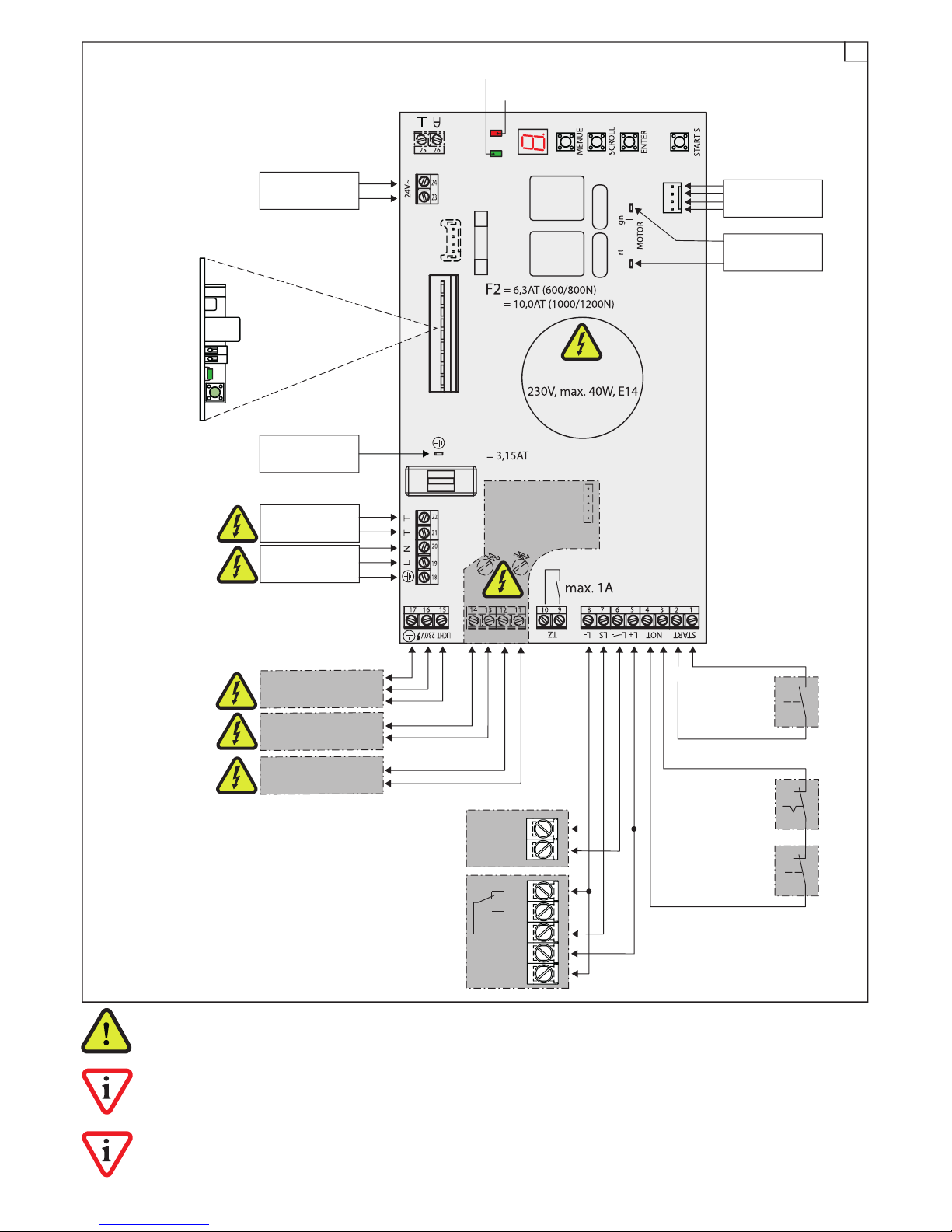
On-site installation and any work on 230 V may only be carried out by qualied and skilled electricians. The connections for the signal, external lighting, mains, transformer (11-22) and the screw terminals for the connection
of the signal module carry 230V!
Only potential-free (= zero voltage) connections may be made at the START (1, 2) and EMERGENCY (3, 4). If the
EMERGENCY connection (3, 4) is not used, the terminals must be connected with a jumper (condition at the time of
delivery).
Only non-latching contacts (e.g. push buttons) may be connected to START (1, 2) and never self-holding or latching
contacts (e.g. switch). Self-holding contacts generate a continuous signal and therefore they block all other functions.
Control board B 300.01-OKP
Wireless receiver on the plug-in
socket "Molex" (B 300.01-OKP)
Motor
24 V/DC
Transformer
Secondary
Earth base
plate
Start
command
Light barrier for receiver
(B210.090)
Light barrier for
transmitter(B210.090)
Motor
Sensor cable
LED green
LED red
Transformer
Primary
Mains power
supply
Lamp
Emergency
Off
Flap door
External lighting
230 V AC max. 60 W
Green signal
230 V AC max. 60 W
Red signal
230 V AC max. 60 W
Signal module
B 300.04
DOCOMATIC 7/23 04-10
Page 8
39
5sec.
1x
1x
1-9x
1x
1x
1x
1x
1-4x
1x
1x
1x
1x
1-5x
1x
1x
1x
1x
1-4x
1x
1x
1x
1x
1-5x
1x
1x
1x
1x
1x
1x
1x
1x
1x
1-7x
1x
1x
1x
1x
1x
1x
L
b
1x
1x
(...)
(...)
1x
1x
1x
1x
ENTER
ENTER
ENTER
ENTER
ENTER
ENTER
ENTER
ENTER
ENTER
ENTER
ENTER
ENTER
START S
START S
START S
MENUE
SCROLL
SCROLL
SCROLL
SCROLL
SCROLL
SCROLL
SCROLL
SCROLL
ENTER
SCROLL
SCROLL
SCROLL
SCROLL
SCROLL
SCROLL
SCROLL
SCROLL
SCROLL
SCROLL
SCROLL
SCROLL
SCROLL
SCROLL
SCROLL
SCROLL
SCROLL
SCROLL
MENUE
MENUE
1x
1x
U
A
H
F
P
ENTER
ENTER
ENTER
ENTER
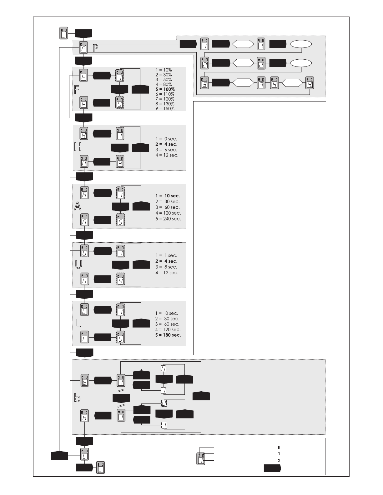
TRAINING PATH AND FORCE - PLEASE NOTE!
•Training the paths can be carried using permanent or multiple individual operations (ne adjustment at the end) of the
"START" button. Reset is not possible!
•Programming the path and force must both be completed
in full.
•After programming the positions "Door open" / "Door
closed" (Indication „3"), by pressing the "START" button once
again the device performs a fully automatic cycle to save
the force curve.
•Power-operated shutdown and safety devices connected
are inactive during the programming phase – in the event of
an overload (e.g. pressing "START" with the door stop in the
end position), fuse F2 will blow!
MENU - PLEASE NOTE!
•The menu must be activated by pressing the "MENUE" button
for about 5 sec. The rst thing to appear in the display is "P".
•With the help of the "SCROLL" buttons you can select the individual menus "P" to "E".
•You can enter the respective menu displayed by pressing the
"ENTER" button once.
•When you enter a submenu "F" to "L" the value set is always
displayed (the characters displayed in bold
represent the pre-programmed factory setting).
You can page through the individual values respectively using
"SCROLL". After reaching the maximum value
pressing the "SCROLL" button once again will display the mini-
mum value. You can quit the respective menu with "ENTER",
which
always saves the current value displayed.
•After completing the settings on "E" you must quit the menu by
pressing the "ENTER" button once.
•The "H" setting is only possible when the signal module has
been installed and "b 3." is inactive or disabled.
•The "A" and "U" settings are only possible when "b 3." is active
or enabled.
•The "L" setting affects both the integrated lighting and any external lighting connected to the terminals 15-17.
•In the "b" menu, the options restricted to 0 or 1 are grouped
respectively in separate and independent submenus. For the
sake of better orientation, please note that the submenus 1.
to 7. are always displayed here with a "." after the digit.
till the door
opens
automatic
till door is opend
Save
Save
1. REVERSING 0 = Full 1= 10cm
2. SOFT MOVEMENT 0 = 7cm 1 = 15cm
3. AUTOMATIC CLOSING 0 = disabled 1 = enabled
4. LIGHT BARRIER 0 = disabled 1 = enabled
5. LIGHT BARRIER 0 = disabled 1 = enabled
6. WARNING LAMP 0 = Flashing 1 = Continuously lit
7. FACTORY SETTING 0 = disabled 1 = Reset
CAPTIONS
User action
LED on
LED off
LED ashes
LED green
LED red
7-segment display
END (Ready for operation)
START (Ready for operation)
Programming of path and force
Shutdown
force
Signal Lead
time
Lead time for
warning lamp
Door open
time
I l l u m i n a t i o n
period
Binary add-on
functions
till the door is
closed
automatic
till door is closed
DOCOMATIC 8/23 04-10
Page 9
1. GENERAL INSTRUCTIONS
Dear Customer, Congratulations on the purchase of this product. The garage door drive has been developed using the
latest state-of-the-art technology and is manufactured by
using the most reliable and modern electrical / electronic
components.
The manufacturer reserves the right to make improvements
or modications to the devices and the assembly and operator manuals at any time without prior notication to this effect.
Please spare a few minutes of your precious time before installing
the equipment and putting it into operation. Please read the
following notes and instructions carefully.
The manufacturer disclaims any responsibility for loss and
damage to property or human injury resulting from improper
installation, commissioning, operation or service and repair
to the garage door, accessories and the drive.
A garage door drive represents an incomplete machine in the context of the Machinery Directive,
2006/42/EC, and the machine is formed using the
combination of the door and drive based on the
conformity evaluation procedure to be carried out
possibly by the manufacturer: the system may only
be commissioned by qualied technicians. The EC
manufacturer's declaration and the CE mark form
part of the commissioning.
It is prohibited to operate the system if the EC
manufacturer's declaration and the CE mark have
not been provided.
1.1 Allgemeine Sicherheitshinweise
IMPORTANT SAFETY INSTRUCTIONS: ATTENTION! IT IS
IMPORTANT FOR SAFEGUARDING HUMAN LIVES TO
COMPLY WITH ALL INSTRUCTIONS!
THIS MANUAL MUST BE PRESERVED UNDER ALL CIRCUMSTANCES! Please ensure that all those who are
entrusted with the operation, maintenance and repair of the system have access to this documentation.
This garage drive door may only be assembled, wired and connected, and commissioned by
qualied technicians. In particular, knowledge and
experience is required in the following areas:
- general and special safety rules and regulations
and accident prevention provisions,
- use of safety equipment and devices,
- EN 13241-1 (Garage door product standard)
- EN 12635 (Installation and operation requirements)
- EN 12453 (Safety issues when using power-opera
ted doors and roller shutters)
- 2006/42/EC (Machinery Directive)
Electrical installations (230V) at site may only be
carried out by skilled electrical technicians.
The safety rules and regulations applicable for accident prevention must be complied with during installation.
The garage drive door may only be installed on a
properly functioning garage door that is balanced
with respect to its weight.
IMPORTANT SAFETY INSTRUCTIONS FOR PREVENTING PERSONAL INJURIES AND DAMAGE TO PROPERTY!
IMPORTANT INSTRUCTIONS FOR PROPER INSTALLATION AND OPERATION!
CONTENTS
Assembly drawings 2
Overview diagram 6
Controller connection diagram 7
Brief instructions on programming 8
1.0 GENERAL INSTRUCTIONS 9
1.1 General notes on safety 9
1.2 Storage and transport 10
1.3 The garage door drive 10
1.4 Scope of supply 10
1.5 Proper use 10
1.6 Prerequisites for installation 10
2.0 ASSEMBLY 10
2.1 Preparatory work 10
2.2 Pre-assembly of the drive 11
2.3 Installing the drive 11
2.4 Afxing warning labels 12
2.5 Manual functional test /
Emergency unlocking 12
3.0 COMMISSIONING 13
3.1 Menu control 13
3.2 Programming path and force 13
3.3 Adjusting the shutdown force 14
3.4 Testing the hindrance detection system 14
3.5 Add-on functions in the menu 14
3.6 Wireless 16
3.7 Teaching the handheld transmitter
(plug-in receiver) 16
3.8 Deleting the handheld transmitter
(plug-in receiver) 16
3.9 Declaration of conformity 16
3.10 Handing over and user training 16
4.0 CONNECTING ACCESSORIES 17
4.1 Push-buttons 17
4.2 Light barrier 17
4.3 Safety switch strip 17
4.4 Antenna (plug-in receiver) 17
4.5 Signal module 18
4.6 Warning lamp / Door status indication 18
4.7 External lighting 18
4.8 Emergency off / ap door contact 19
4.9 Centre suspension 19
5.0 OPERATING THE SYSTEM 19
5.1 Instructions for safe operation 19
5.2 Operation 20
5.3 Fault indications 20
5.4 Rectifying faults 21
5.5 Maintenance and repair 22
6.0 DISPOSAL 22
7.0 TECHNICAL SPECIFICATIONS 22
8.0 ACCESSORIES 23
EC Explanation of installation
DOCOMATIC 9/23 04-10
Page 10
1.2 Storage and transport
• The garage door drive may only be stored lying down and transported under the following environmental conditions:
-20°C to +40°C / 20-80% RH (relative humidity) non-condensing.
• When stacking the equipment, please note that the maximum height of 6 motor heads or 6 rails must not be exceeded.
Equipment that is completely packed (kit cartons) can be stacked up to a maximum height of 6 devices.
• While stacking the garage door drives, care must be taken to ensure that they or their components do not fall down.
• Equipment damaged by water or other noticeable damage to the housing, motor shaft, drive rail, carriage, push rod,
door ttings, power cable, xing materials or any parts of these components may not be installed for safety reasons.
1.3 The garage door drive
The garage door drive is a microprocessor-controlled appliance designed in accordance with the latest European standards. The drive is self-inhibiting and keeps the garage door locked.
1.4 Scope of supply
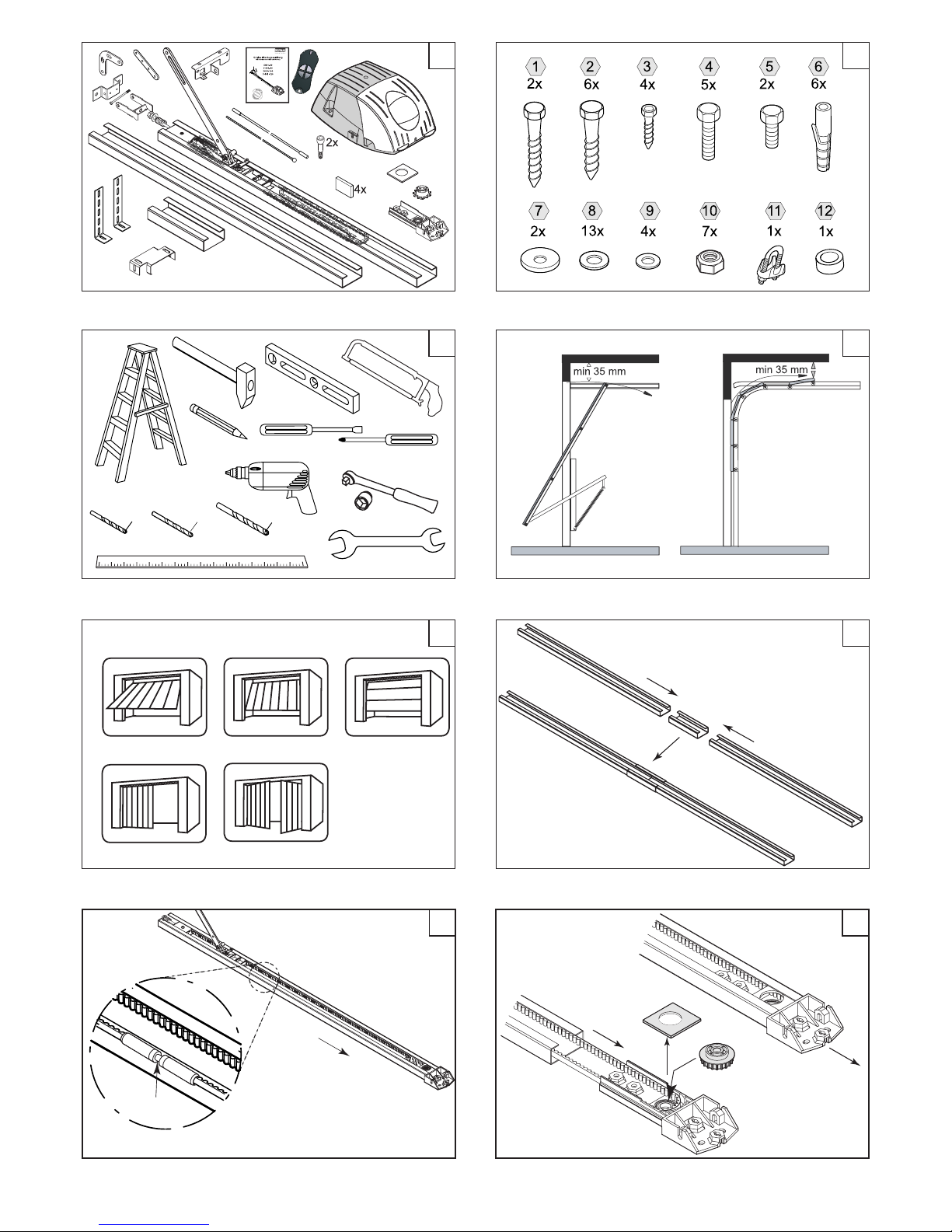
Depending on the rail version, the scope of supply can deviate (*) from the components illustrated (FIG. 1, FIG. 2).
1.5 Proper use
The garage door drive is only designed to open and close individual garage doors that are balanced by weight. The garage door drive may only be used in dry areas and spaces.
(FIG. 5) The garage door drive can be used with the following types of garage doors: Hinged (a), overhead tilting (b), sectional (c), side-sectional (d) and two-winged hinged doors opening outwards (e). The curved door arm may be necessary
for overhead tilting doors. The winged door tting accessory is required for hinged doors.
1.6 Prerequisites for installation
• ((FIG. 4) There must be a clearance of at least 35 mm between the highest point of the upper edge of the garage door
and the roof in order to install the appliance.
• The maximum values and forces specied in the section on Technical Specications must be taken note of and complied
with.
• The mechanical locking systems of the garage door must be dismantled or deactivated prior to installing the drive.
• Before installing the drive, the garage door must be in proper mechanical condition. It must be possible to operate the
door by hand without applying any large amount of force and it must remain xed in any position when it is stopped. The
garage door must be checked by qualied specialists and, if the above condition is not fullled, it must be repaired before
installing the drive.
• The lintel and the garage roof must be constructed in such a manner that the drive can be secured to it safely.
• The minimum load-bearing capacity of the lintel and roof must be 700 N (approx. 70 Kg.).
• The xture of the garage door holder (FIG. 25) has been designed for garage doors having a xed and reinforced upper
edge of at least 1.5 mm thickness. For weaker doors, please use suitable xing materials (e.g. accessories for the sectional
door tting BY 4720).
• The installation or use of other parts can jeopardise the operational safety and hence they are prohibited.
• In accordance with EN 12453, the drive may not be used on doors that are located in public places or that require an
increased minimum level of protection.
2.0 INSTALLING THE DRIVE
IMPORTANT INSTRUCTIONS FOR SAFE INSTALLATION. PLEASE FOLLOW ALL INSTALLATION INSTRUCTIONS IN THE SEQUENCE SPECIFIED - INCORRECT OR IMPROPER INSTALLATION CAN CAUSE FATAL INJURIES!
Before proceeding with the installation, please ensure that the mains plug has been removed. Safeguard the equipment against the mains plug being reinserted.
Prior to installation, ensure that the garage door is in proper and working condition.
2.1 Preparatory work
You should do some preparatory work so that the installation can be completed expeditiously:
• Read the installation manual completely before commencing work, since it contains important information for installation
• Learn about the roof thickness and, if applicable, any cables / pipes that have been laid (hazard of drilling through them!).
• Check the scope of supply. Keep any accessories that may be required or desired ready at hand.
• Keep all tools (FIG. 3) as well as suitable material, if required, at hand to cover the drive when drilling bore holes (dust hazard) and any aids, if necessary, to support the drive (hazard of the drive falling down).
DOCOMATIC 10/23 04-10
Page 11

• Put all those mechanical locks and devices of the garage door, which are not required after installing the drive, out of
operation and remove them.
• Please note that the drive is installed with the garage door closed: all tools and tackles required must be kept inside the
garage if it does not have any other access route.
2.2 Pre-assembly of the drive
FIG. 6: Pre-assemble the rails
• Depending on the model of the equipment, the rails must rst be pre-assembled. First plug the rails into one another with
the help of the cap rails. The rails must be pushed into one another up to the stop points.
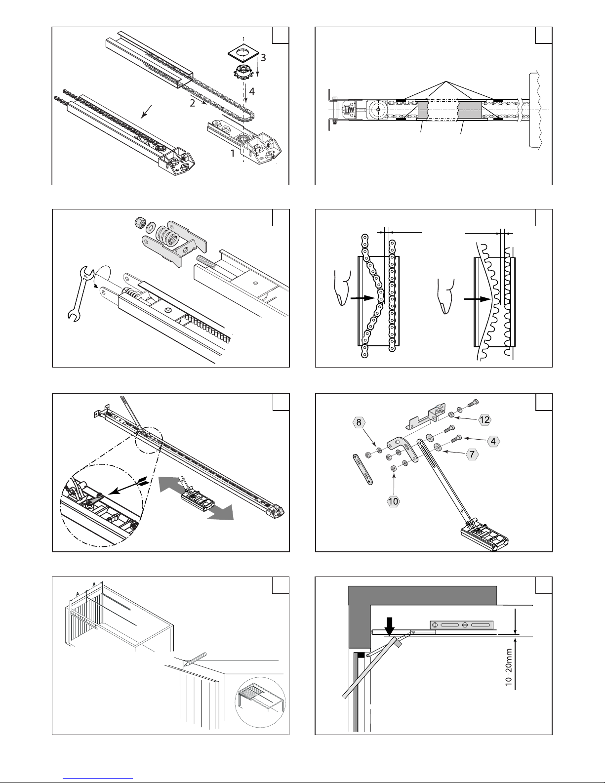
FIG. 7: Put the chain / toothed belt in place
• Pull the chain / toothed belt already in the rail in the direction of the open end of the rail. When doing so, please ensure
that the attachment (a) is located on the correct side of the rail.
FIG. 8: Mount the head retainer (toothed belt version)
• Pull the head retainer (1) out of the rail (2). Remove the transportation lock (3). Place the drive wheel (4) into the ballbearing and push the head retainer back into the rail.
FIG. 9: Mount the head retainer (chain version)
• Pull the head retainer (1) out of the rail. Attach the sprocket (4) and the transportation lock (3) and push the head retainer
back into the rail.
FIG. 10: Put the rubber liner in place (only chain version)
• To prevent vibrations at the points marked with "c", afx the self-adhesive rubber liner as close as possible to the end of the
rail in the front (a) and at the rear (b).
FIG. 11: Mount the clamp
• Pull the chain / toothed belt already in the rail in the direction of the open end of the rail. When doing so, please ensure
that the attachment (a) is located on the correct side of the rail.
• Next, x the deection roller assembly to the clamp as shown. While doing so, please ensure that the square-shaped end
of the mushroom head bolt is correctly seated in the deection roller assembly holder.
FIG. 12: Tighten the drive medium
• The chain or the toothed belt must then be pre-tensioned to such an extent that the chain or the toothed belt does not
drop down any longer.
FIG. 13: Test the carriage
• Finally, check whether the carriage can be moved easily in the rail. To do this, operate the emergency unlocking lever on
the carriage and move it in the rail simultaneously.
• Make sure to check that the carriage is latched onto the attachment after this test. For this purpose, move the carriage
over the attachment, while the emergency unlocking lever is not in operation, so that the carriage latches automatically.
FIG. 14: Mount the door tting
• Different installation parts can be used for those versions of the appliance with a straight push rod (a): the straight extension can be used for overhead tilting doors (d) and the sectional door bracket (c) can be used for sectional doors. The
standard version of the equipment uses a curved push rod (a) and no other installation parts are supplied or used.
• Following this, the door tting (b) is mounted on the push rod (a).
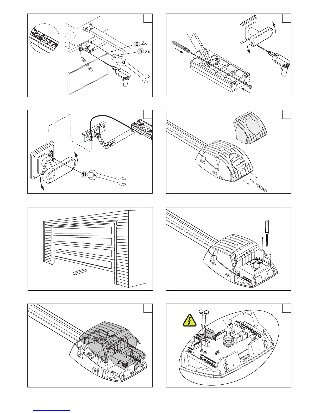
2.3 Installing the drive
FIG. 15: Mark the centre of the door
• Measure the width of your door and mark the centre of the door at the lintel, the upper edge of the door and on the
garage roof (behind the opened door and near the motor head).
FIG. 16/17: Obtaining the required height
• The rail must be mounted in such a way that there is about 10-20 mm clearance between the highest point of door movement (a) (the highest point that the top edge of the door can reach during its movement) and the bottom edge of the
rail (b). In the process, however, please ensure that the rail is always mounted horizontally.
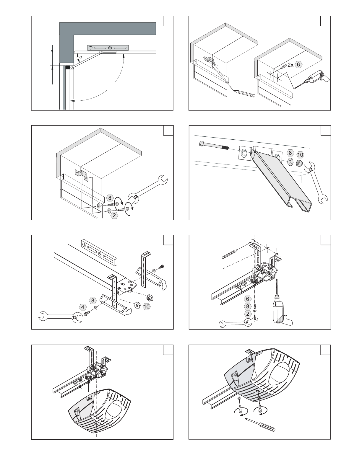
• The angle α may not exceed 30°, otherwise proper power transfer cannot be guaranteed.
• The distance between the lower edge of the rail and the upper edge of the garage door must be between 5 and 7 cm
when the door is closed.
DOCOMATIC 11/23 04-10
Page 12
FIG. 18/19: Mounting the lintel xture
• Place the lintel xture supplied along with the equipment based on the dimensions obtained (centre of the door, installation height) on the lintel (depending on the site conditions, the xing screws supplied may have to replaced with other
suitable ones). Please note: Cover the drive when performing any drilling work!
FIG. 20: Fix the rail on the lintel
• Finally, mount the rail on the lintel xture.
FIG. 21: Position the slotted brackets
• In the next step, the slotted brackets are xed to the rail. The required dimensions are derived from the installation height
obtained earlier (ensure horizontal installation of the rails!).
FIG. 22: Fixing the drive to the roof
• Following this, swing the rail up to the garage roof. Please ensure that the rail is aligned in the centre of the door marked
previously. Prevent the rail from falling down. Mark the bore holes.
• Fix the rail to the garage roof using suitable dowels, screws and at washers.
FIG. 23/24: Mount the drive head to the rail
• Fix the drive head with the motor axis on the pinion located in the rail.
• Finally, tighten it using the screws supplied.
FIG. 21-24: Alternatively, the roof xture can also be connected directly to the drive head using the slotted brackets; see
the overview drawing.
FIG. 25: Fixing the garage door holder
• First, manually unlock the carriage and push it in the direction of the lintel.
• Then x the door holder to the door using at least 4 screws.
FIG. 26/27: Install the emergency unlocking mechanism
• Installation of the external unlocking mechanism is absolutely necessary for garages that do not have a second access
route, so as to be able to open the garage from outside in case of an emergency. If no internal twist grip is available, the
emergency unlocking mechanism must be installed using a key lock (Item no. B 146.02, accessories). Please check to see
if the emergency unlocking mechanism is working (see 2.5).
FIG. 28: Put the light cover in place
•After all of the work has been completed, please ensure that the light cover is put back in place and fastened with the
screw provided.
2.4 Afx warning labels
The warning label, which draws attention to the risk of jamming and serves as a reminder for regular checking of
the hindrance detection system, must be permanently afxed at a clearly visible location or in the vicinity of the
operating elements that have been installed permanently.
The warning label that contains notes regarding the operation of the emergency unlocking mechanism must be
xed permanently near it and must be clearly and easily visible.
The warning label that advises children to stay away from the area of the open door must be xed permanently
near the pivoting range and it must be clearly and easily visible.
2.5 Manual functional test / Emergency unlocking test
After completing the installation, please ensure that the functioning of the garage door has not been affected by installing
the drive.
• Disconnect the mains plug. Unlock the garage door drive using the emergency unlocking mechanism. Please note that
there can be uncontrolled movements in the event of broken spring / cable or if the door is not properly balanced!
• Open and close the door manually a number of times (when doing so, every time that the carriage (FIG. 11) is pulled
over the attachment (FIG. 8, a), the emergency unlocking mechanism must be pulled) and ensure that the garage door
moves easily in the process. While doing so, the carriage of the drive may not collide with the deection roller at the front
or the drive head at the rear under any circumstances. The garage door may not collide with the drive.
• Check the cord tension of the emergency unlocking mechanism. In the closed condition, the cord must be slightly taut so
that operating the door twist grip is enough to operate the emergency unlocking lever at the carriage of the drive and to
unlock the carriage. The cord may not slacken while the door is in motion.
• Move the garage door until the attachment latches again. It should no longer be possible to move the garage manually.
mm0
5
DOCOMATIC 12/23 04-10
Page 13
3. COMMISSIONING
If the springs are weak or broken, or the weight of the door is not balanced properly, operating the drive can lead
to uncontrolled movements of the door.
During commissioning, you must remain inside the garage. This means that you can open the door using the manual
unlocking mechanism in the event of a fault.
3.1 Menu controls
ALL FUNCTIONS, OPERATING SEQUENCES AND ADJUSTMENT & SETTING OPTIONS HAVE BEEN PRESENTED AT A GLANCE
AND AS BRIEF INSTRUCTIONS ON PAGE 8 OF THIS MANUAL!
First, loosen the screw on the light cover. Remove the light cover from the housing (FIG. 28).
OPERATING THE MENU CONTROLS
1) ENABLING (ACTIVATING) THE MENU:
Press the MENU button and hold for about 3 sec.: The green LED begins to ash, and in the multi-segment display (hereinafter
referred to as "Display") the rst submenu "P" (= Program, learn drive) appears.
2) NAVIGATION WITHIN THE MENU:
You can enter the menu option displayed respectively with a single character by pressing briey on the ENTER button ("Conrm selection") or switch to the next menu option by pressing briey on the SCROLL button ("Page"); the sequence is xed
and paging always takes place in one direction (see sequence in the description of the menu options)!
3) NAVIGATION IN THE MENU OPTION (! Please take note of the exceptions in "P" and "b" !)
If you have selected the desired menu option by pressing briey on the ENTER button, the display then switches to a numerical value between "1" and "9", which represents the status of the function or setting that has been congured: by pressing
briey the SCROLL button, you can page through these setting options, which are always in increasing order; if the respective maximum value is reached, pressing the SCROLL button once again restarts paging with "1".
Page through the options with the SCROLL button until you reach the desired selection and conrm it by briey pressing the
ENTER button: The display changes once again to that of the menu option, and the desired value set by you is accepted.
4) SAVE AND QUIT MENU:
The last menu option is "E" ("End"), which does not provide any setting options and merely displays the end of the menu:
Briey press the ENTER button in order to quit the menu and to save the settings selected (green LED goes off). If you wish to
return to the menu, press the SCROLL button instead: in this case, the menu begins once again with the rst menu option "P".
3.2 Programming path and force ("P")
The attachment (FIG. 7, a) must be latched and locked in the carriage (FIG. 13). The factory setting for the force (stage 5)
may not be changed before performing the learning procedure!
During the learning movement, evaluation of the light barrier and hindrance detection system or the power-operated shutdown does not take place!
Nobody may remain in the hazard zone of the garage door during commissioning and when adjustments are being
made!
• Enter (activate) the menu and go to the menu option "P" with ENTER: "1." appears in the display. Activate the drive in the
open direction by pressing the START button (display switches to "1.") and stop it just before it reaches the end position
"Door open"; move it the last few centimetres by pressing the button briey and repeatedly in order to ensure the correct
end position.
• End the procedure by pressing briey on the SCROLL button, enable (activate) the stand-by for closing, and "2" appears
in the display.
• Re-activate the drive by pressing the START button (display switches to "2.") and stop it just before it reaches the end po-
sition "Door closed"; move it the last few centimetres by pressing the button briey and repeatedly in order to ensure the
correct end position.
• End the procedure by pressing briey on the SCROLL button, enable (activate) the readiness for the subsequent learning
movement for force measurement: "3" appears in the display.
• Now press the START button briey: the display changes to "3." and the drive performs a complete and automatic cycle
from an open condition to close, in order to obtain the exact values of the force. The display switches to "4." at the end of
the door opening movement, as well as at the beginning of the close operation. If the door is closed again, the procedure
ends, and the display indicates this status by returning to the menu: "P" appears in the display:
• Quit the menu by pressing the SCROLL button and paging to the end of the menu "E" and quit the menu with ENTER (alter-
natively: congure other desired settings in the subsequent menu options).
DOCOMATIC 13/23 04-10
Page 14
3.3 Adjusting the shutdown force ("F")
CAUTION: Do not set the value of the shutdown force for hindrance detection too high, as this can lead to damage
to property and human injury. If the drive power is adjusted in such a manner that a force greater than 150 N is applied at the door edge or the shear points before automatic shutdown takes place, additional safeguard must be
provided by means of a light barrier or some other equivalent device.
Following any modications to the settings for the shutdown force or after each learning movement, please check
that the drive reverses when the door touches an object that is 50 mm in height and that has been placed on the
ground (FIG. 29; see also Hindrance detection, 3.4).
The factory setting is "5" (= 100%). In the case of a door that is working properly, there should be no need to change and
increase the value of the force after programming the path and force (3.2)- in any case, please check that the door works
properly when operated manually before making any changes to the settings for the value of the force!
• Enter (activate) the menu and go to the menu option "F" with ENTER: the value congured appears in the display.
• Using the SCROLL button, page to the desired setting and conrm this by pressing the ENTER button, which saves the setting, and return to the menu (display shows "F" again).
• Use the SCROLL button to page to the end of the menu ("E") and quit the menu by pressing briey on ENTER (alternatively:
congure other desired settings in the subsequent menu options).
3.4 Testing the hindrance detection system
After adjusting the drive, please check that the shutdown force for hindrance detection has been set in such a way that the
door stops and reverses when it encounters a hindrance. The hindrance detection system can be tested by placing a piece
of wood that is at least 50 mm in height on the oor in the path of movement of the door and allowing the door to close
(FIG. 29). When encountering the hindrance, the door must stop immediately and start reversing. If this does not happen,
the value of the shutdown force must be corrected by reducing it!
If the drive is used on a door, which has perforations in the door wing >Ø 10 mm or has edges or protruding parts that
can grip a human being or which can stand on the door, please ensure that the drive prevents the opening movement or stops if the door encounters a mass of 20 Kg. at the centre of the lower edge of the door (safety shutdown
to protect against lifting human beings / other objects).
3.5 Add-on functions in the menu
The add-on functions listed in the following passage are used to adjust and adapt the garage door drive to every
specic installation and therefore they should only be used in case of adaptation to the application. Further information regarding the conguration and setting options is also provided in the brief instructions (page 8) and in the
information on accessories (4.0 ff).
H: Signal lead time
In the menu option H you have the option tof setting the lead time for any red signal that may have been installed (only if
the signal module, compare 4.5, has been installed. The lead time is the time period between the start command and the
commencement of drive movement.
• Enter (activate) the menu and go to the menu option "H" with ENTER: the value congured appears in the display.
• Use the SCROLL button to page to the desired setting and conrm this by pressing the ENTER button, which saves the setting, and return to the menu (display shows "H" again).
• Use the SCROLL button to page to the end of the menu ("E") and quit the menu by pressing briey on ENTER (alternatively:
congure other desired settings in the subsequent menu options).
A: Door open time
IYou can dene the time period for keeping the door open in the menu option A (only if the "Automatic door closing" feature
is enabled, see 3.5 / b: binary add-on functions / POINT 3). The door open time is the time period between "Door open" and
the door being closed.
• You can dene the time period for keeping the door open in the menu option A (only if the "Automatic door closing"
feature is enabled, see 3.5 / b: binary add-on functions / POINT 3). The door open time is the time period between "Door
open" and the door being closed.
• Using the SCROLL button, page to the desired setting and conrm this by pressing the ENTER button, which saves the setting, and return to the menu (display shows "A" again).
• Use the SCROLL button to page to the end of the menu ("E") and quit the menu by pressing briey on ENTER (alternatively:
congure other desired settings in the subsequent menu options).
U: Lead time for warning lamp
You can set the lead time for the warning lamp connection (see 4.6) on terminals 9/10 in the menu option U (only if the "Automatic door closing" feature is enabled, see 3.5 / b: binary add-on functions / POINT 3).
• You can set the lead time for the warning lamp connection (see 4.6) on terminals 9/10 in the menu option U (only if the
DOCOMATIC 14/23 04-10
Page 15
"Automatic door closing" feature is enabled, see 3.5 / b: binary add-on functions / POINT 3).
•Using the SCROLL button, page to the desired setting and conrm this by pressing the ENTER button, which saves the setting, and return to the menu (display shows "U" again).
• Use the SCROLL button to page to the end of the menu ("E") and quit the menu by pressing briey on ENTER (alternatively: congure other desired settings in the subsequent menu options).
L: Illumination period
In the menu option L you can set the time period for the internal lighting and external lighting (4.7) to be connected to the
terminals 15/16.
• Enter (activate) the menu and go to the menu option "L" with ENTER: the value congured appears in the display.
• Using the SCROLL button, page to the desired setting and conrm this by pressing the ENTER button, which saves the setting, and return to the menu (display shows "L" again).
• Use the SCROLL button to page to the end of the menu ("E") and quit the menu by pressing briey on ENTER (alternatively:
congure other desired settings in the subsequent menu options).
b: Binary add-on functions
In the menu option b you can select the functions listed below. Please note, that the menu option b works with submenus
(see brief instructions on page 8; factory settings are illustrated there).
• Enter (activate) the menu and go to the menu option "b" with ENTER: "1." appears in the display.
• Page with the SCROLL button to the desired function and call up this MENU.
• Use the SCROLL button to page to the desired setting and conrm this by pressing the ENTER button, which saves the setting, and return to the submenu (display shows "(digit X)." again).
• Quit the submenu by pressing ENTER, and "b" appears once again in the display.
• Use the SCROLL button to page to the end of the menu ("E") and quit the menu by pressing briey on ENTER.
POINT 1: REVERSING BEHAVIOUR
This species whether the drive performs a partial or complete reversal when a hindrance is detected.
POINT 2: SOFT MOVEMENT FUNCTION
This enables the selection of a short (approx. 7 cm) or long (approx. 15 cm) soft movement function at the beginning and
end of the door movement; the longer phase leads to more gentle braking and closure.
POINT 3: AUTOMATIC DOOR CLOSING
Enabling (activating) the automatic door closing requires additional protection for the machine depending on
the type of door operation and utilisation (compare EN 12453), e.g. with closing edge protection and / or detecting the presence of human beings using safety switch strips, light barriers as well as warning devices, if any,
such as a warning lamp!
This allows you to enable or activate the automatic door closing feature after a variable period of time for which the
door has remained open; this door open time can be set in the menu option A after the automatic door closing feature
has been enabled.
POINT 4: LIGHT BARRIER
This permits the light barrier connection on the terminals 5-8 (see 4.2) to be enabled or activated.
POINT 5: SAFETY SWITCH STRIP
This enables the evaluation of a safety contact switch strip with 8.20 or 22.00 Kohm on the terminals 5-8 (see 4.3).
POINT 6: WARNING LAMP
This enables the conguration of the connection on terminals 9, 10 (see 4.6) as an output for a ashing signal for warning
lamps (without its own asher electronic circuit) or as an output with a continuous signal (for asher lamps having their
own electronic asher circuits).
This enables the conguration of the connection on terminals 9, 10 (see 4.6) as an output for a ashing signal for warning lamps (without its own asher electronic circuit) or as an output with a continuous signal (for asher lamps having their own electronic asher circuits).
POINT 7: RESET FACTORY SETTINGS
This resets the values in all menu functions to the default factory settings.
DOCOMATIC 15/23 04-10
Page 16
3.6 Wireless
The following models pertain to equipment tted with the BERNAL-Keeloq® wireless system "PICO" 868.5 MHz.
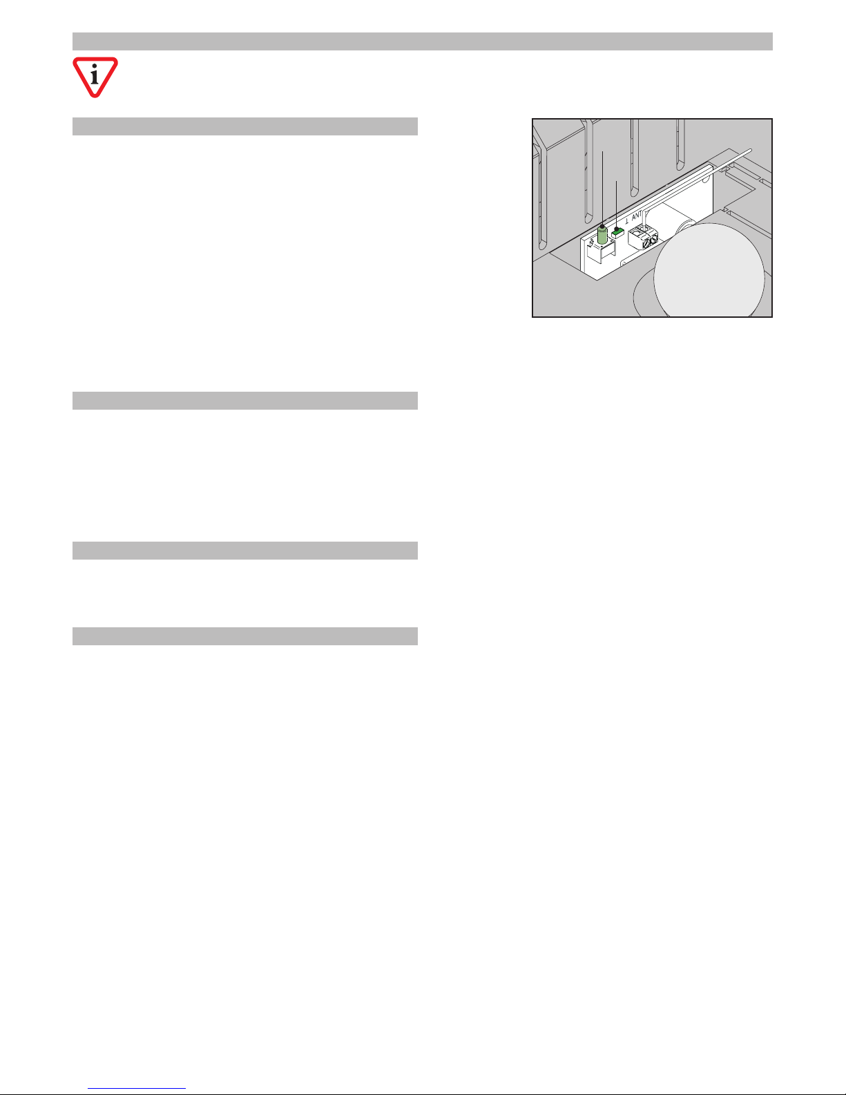
3.7 Teaching the handheld transmitter (plug-in receiver)
A maximum of 28 handheld transmitters can be programmed on the wireless
receiver. At the end, the initial codes will be overwritten
• Plug in the mains supply.
• Loosen the screw on the light cover. Remove the light cover from the
housing.
• Press the WIRELESS LEARN button on the plug-in receiver briey. The WIRELESS LED on the plug-in receiver lights up.
• Press the desired button of the handheld transmitter until the WIRELESS LED
goes off.
• the button of the handheld transmitter once again until the WIRELESS LED
starts ashing.
• WIRELESS LED goes off after about 5 sec., and the handheld transmitter has
been taught.
Repeat the procedure for teaching other handheld transmitters. If no handheld transmitter is trained within 30 sec. after
activation, the learning mode ends automatically.
3.8 Deleting the handheld transmitter (plug-in receiver)
If handheld transmitters are to be deleted from the wireless receiver, the latter must be deleted completely:
• Plug in the mains supply.
• Loosen the screw on the light cover. Remove the light cover from the housing.
• Press the WIRELESS LEARN button on the plug-in receiver (and hold it). The WIRELESS LED lights up and goes off after about
10 sec.: All trained handheld transmitters are deleted.
3.9 Declaration of conformity
Finally, the manufacturer of the machine or his authorised representative must effect the EC Declaration of Conformity in
accordance with MRL 2006/42/EC Appendix II 1.A. and the CE mark in accordance with MRL 2006/42/EC Appendix III.
3.10 Handing over and user training
Hand over the machine including the documentation (see EN 12635) to the owner of the system. Please ensure that the
operator and user are briefed and trained in the operation and maintenance of the system. Please ensure that these authorised persons receive:
• training on operating the system safely (see 5.0 to 5.3),
• training in the maintenance of the system (see 5.5) as well as
• brieng on possible hazards of non-compliance with these instructions.
In addition, please give a live demonstration on the machine regarding:
• the function of all operating elements and their effect during various operating states (5.2),
• the function and testing of the emergency unlocking mechanism (2.5),
• the function and testing of the hindrance detection system (3.4) and
• the operation and testing of all and/or any additional safety devices connected (4.2 / 4.3 / 4.5 / 4.6 and 4.8).
Please draw attention to the fact that the instruction manual for the machine must be kept in safe custody in such a manner
that all those concerned with the operation, maintenance or repair of the machine have access to it. Please recommend
that a test logbook be maintained and that the system is checked once every year by a qualied technician, even for
systems that belong to an individual household not having automatically operated garage doors. Please document the
handing over and the user brieng and training in writing.
DOCOMATIC 16/23 04-10
Page 17
4.0 CONNECTING ACCESSORIES
Remove the mains plug before laying any wiring or connections to the controller in order to prevent damage to the
controller!
Always lay the control and signal lines in such a way that they are separate and isolated from power cables in
order to prevent interferences.
4.1Buttons
Only non-latching NO (normally open) contacts (not self-holding or latching contacts of a switch or similar!) may
be used! Only potential-free contacts may be connected - never connect any external power supply!
Connect the button contacts to terminals 1 and 2 of the control board (FIG. 38). If more than one element is used for this
connections, the contacts must be connected in parallel. Use cables having a core diameter of at least 0.25 mm² for maximum length of 20 m. Operating elements that are permanently installed must be within sighting range of the garage door.
The distance between moving parts and the height above the ground must be at least 1.8 metres. They must be mounted
beyond the reach of children under all circumstances!
4.2 Light barrier
The light barrier must be enabled (activated) in the menu "b" option "4" (see 3.5 or the brief instructions on page 8)!
The use of a light barrier generally enhances the safety of the garage door system and can become urgently necessary
under certain circumstances (e.g. contact with public places or minimum level of protection in accordance with EN 12453).
If the light beam gets interrupted during the door closing movement, the garage door stops immediately and reverses
about 10 cm in the direction of door opening (or performs complete reversal: see 3.5 / b: binary add-on functions / POINT
1). The light barrier is inactive during the door opening movement.
Use cables with a core diameter of at least 0.25 mm² for a maximum length of 20 m. We recommend that the light barrier
be located at a height of 40 cm above the ground and as close as possible to the door (max. 50 mm away). If more than
one pair of light barriers is used, they must be installed opposite one another and connected in series.
The positive voltage supply (+24 V) of the transmitter light barrier TX and receiver light barrier RX is fed on terminal 5. The
negative power supply (0 V) of the transmitter light barrier is fed at terminal 6 (wired earth), and the negative voltage supply
of the receiver light barrier is connected to terminal 8 (earth). Connect the signal output of the receiver light barrier (RX) to
terminal 7 (S) and to earth (terminal 8). After completing the installation, test the operation of the light barrier by interrupting
the light beam using some object (e.g. a broom).
4.3 Safety switch strip
The safety switch strip must be enabled (activated) in the menu "b" option "5" (see 3.5 or the brief instructions on
page 8)!
The controller allows direct evaluation of the resistive safety switch strips with 8, 20 and 22.00 Kohm. If a light barrier is not used
simultaneously, the safety switch strip is connected directly to the terminals 7 (signal) and 8 (earth).
If light barriers and safety switch strips are used simultaneously, the latter must be wired in series with the receiver signal of
the light barrier after the terminal 7 (signal). In this case, both the devices must be enabled in
menu "b" ("4" as well as "5"), i.e. dened as active. After completing the installation, test the operation of the safety switch
strip by manually applying counter-pressure to it.
4.4 Antenna (plug-in receiver)
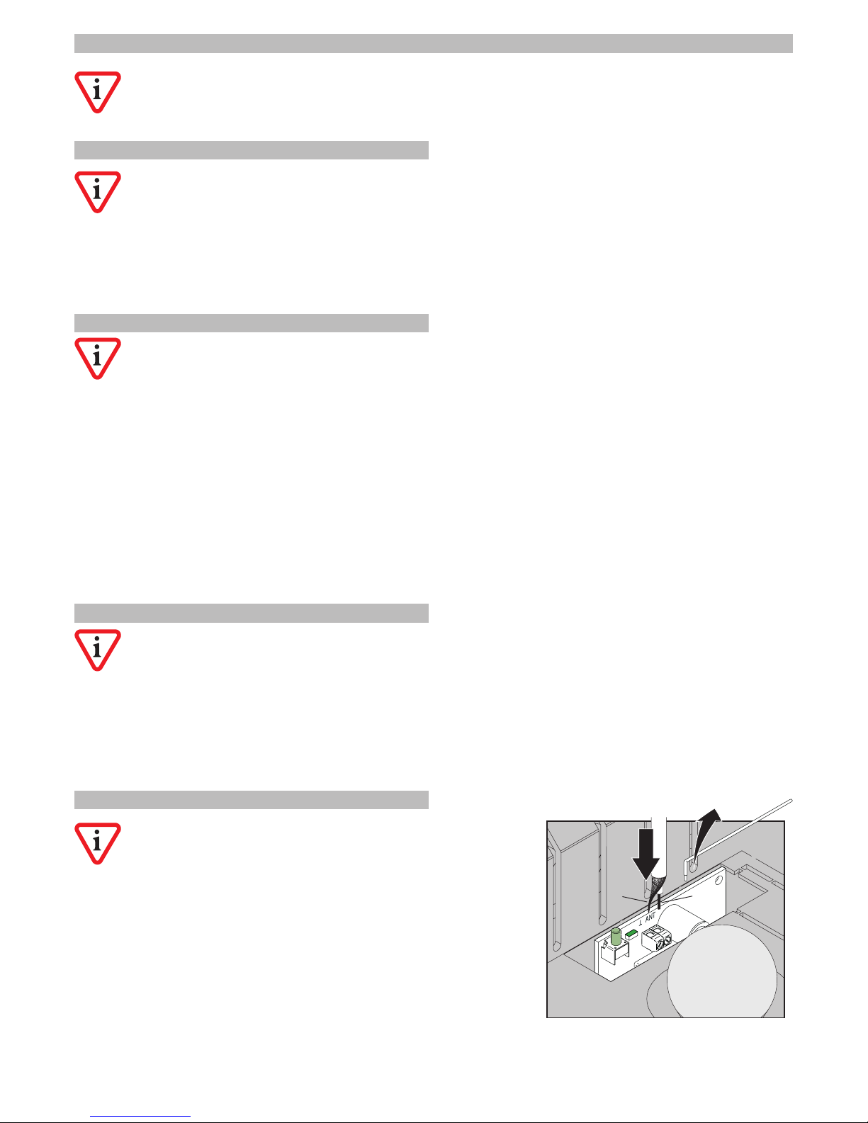
Please use only an antenna with a suitable (=matching) frequency
and screened (or shielded) coaxial cable. Do not modify the antenna
under any circumstances.
• Remove the dipole (wire) antenna xed to the antenna connection ANT of
the wireless receiver.
• Connect the inner conductor (1) of the supplementary antenna to the antenna connection ANT and connect the screen (or shield) (2) to the ┴ terminal.
• Lay the antenna outside the garage and place it at a point that is exposed
and at as high a location as possible with a line of vision to the operating
location.
Do not extend the coaxial cable provided on the antenna and do not use
more than one antenna simultaneously on the device.
1
2
DOCOMATIC 17/23 04-10
Page 18
4.5 Signal module
Using the optional signal module B 300.04, red and green signal lamps of up to max. 60 W respectively can be connected
to the 230 V supply.
FUNCTION:
While opening, the red signal lights up or starts ashing after input of the start impulse (setting via menu, see 3.5 / b: binary
add-on functions / POINT 6 or brief instructions on page 8).
After expiry of the lead time that can be set in various steps of 0 -12 sec. (menu H, see 3.5 / H: Lead time for the signal or
brief instructions on page 8) the door starts moving and the red signal lamp lights up permanently. If the door is open, the
red signal lamp goes off and the green signal lamp lights up.
While closing, the green signal lamp goes off once the start impulse is input and the red signal lamp lights up or begins to
ash. After the lead time has elapsed the door begins to move and the signal changes to continuous red light. The red signal
lamp goes off once the door is closed.
ATTENTION - DANGER TO LIFE! The screw fasteners of the signal module are also used to feed the power supply to
the signal connection; they carry 230 V AC! Ensure that the drive has been unplugged from the mains supply when
any work is being done, and prevent it from being plugged in!
INSTALLATION:
• (FIG. 28) Disconnect the power supply to the drive (remove the plug) and take off the light cover.
• (FIG. 30/31) Unscrew the hood and remove it.
• (FIG. 32) Remove the caps of the screw fasteners, place the signal module and fasten it with screws, and put on the caps
again.
• Fasten and tighten the hood with the screws, and then you can connect the signal to the terminals of the signal module.
Please use cable cores having min. 0.75mm² up to a maximum length of 20 m.
• Put the light cover back in place and fasten it.
After installing the signal module, the warning lamp connection (terminals 9/10) works automatically as a door status indication (see 4.6), since the warning or ashing feature must be implemented via the red signal lamp.
The potential-free connection for warning lamp / door status indication must be protected externally with a fuse
rating of max. 1A, in order to rule out any damage to the controller. The maximum contact load-bearing capacity
is 1A on 230 V AC or 30 V DC.
Use suitable cable for the connection of the door status indication or warning lamp in keeping with the voltage / load used.
We recommend that the warning lamp be installed at a point that is exposed as far as possible and, above all, can be seen
easily from all positions at risk from the door movement.
Door status indication:
As a rule, if the signal module is installed (see 4.5), the connection at terminals 9/10 acts as the door status indication; it generates a continuous signal when the status is "Door closed", which can be wired with any desired application. The same is
true when the signal module is not plugged in and when the automatic door close feature is disabled (inactive) (see 3.5 /
binary add-on functions / POINT 3).
Warning lamp:
When the signal module is not plugged in (see 4.5) but the automatic door close feature is enabled (active) (see 3.5 / b:
binary add-on functions / POINT 3) the connection at terminals 9/10 works, in general, as a warning lamp connection.
You have the option of connecting a warning lamp (without integrated ashing control electronics) or a ashing lamp (with
integrated ashing control electronics). You can make this selection in the menu (see 3.5 / b: binary add-on functions /
POINT 6 or brief instructions on page 8).
The lead time can be congured in the menu from 0 - 12 sec. (see 3.5 / U: Lead time for warning lamp or brief instructions
on page 8).
4.7 External lighting
ATTENTION - DANGER TO LIFE! Terminals 15/16 for the external lighting carry 230 V AC! Ensure that the drive has been
unplugged from the mains supply when any work is being done and prevent it from being plugged in!
An external supplementary lamp of 230 V AC up to max. 60 W or a switching relay can be connected directly to terminals
15/16/17. The connection is held live for the same period of time as that of the lighting of the drive-internal illumination
and can be set in various steps (see 3.5 / L: lighting period or brief instructions on page 8). We recommend
the use of cable cores having a cross-section of at least 0.75mm² up to a total length of max. 20 m.
DOCOMATIC 18/23 04-10
4.6 Warnleuchte/Torzustandsmeldung
DOCOMATIC 18/23 04-10
Page 19
4.8 Emergency off / ap door contact
ATTENTION! The factory-tted wire jumper across the terminals 3/4 may not be removed under any circumstances
if the connection is not being used - this prevents the device from starting!
Potential-free NC (normally closed contacts) of any safety device or its signal transmission can be connected to the terminals 3/4.
In general, triggering the connection prevents the drive from starting when it is at a standstill; triggering the connection
while opening causes the drive to stop immediately and start reversing (direction reversal after opening). After resetting the
trigger, the drive can be operated again in the regular manner.
Before connecting an element, remove the factory-tted wire jumper. Use a cable core of at least 0.25mm² cross-section
for the connection with a maximum length up to 20 m. If a number of elements are operated at this connection, the NC
contacts must be connected in series.
4.9 Centre suspension
The centre suspension provides extra stability to the drive depending on the installation conditions, such as heavy doors or
drives having extended rails (> 3.00 m). It has not been designed to be the only means for xing the drive.
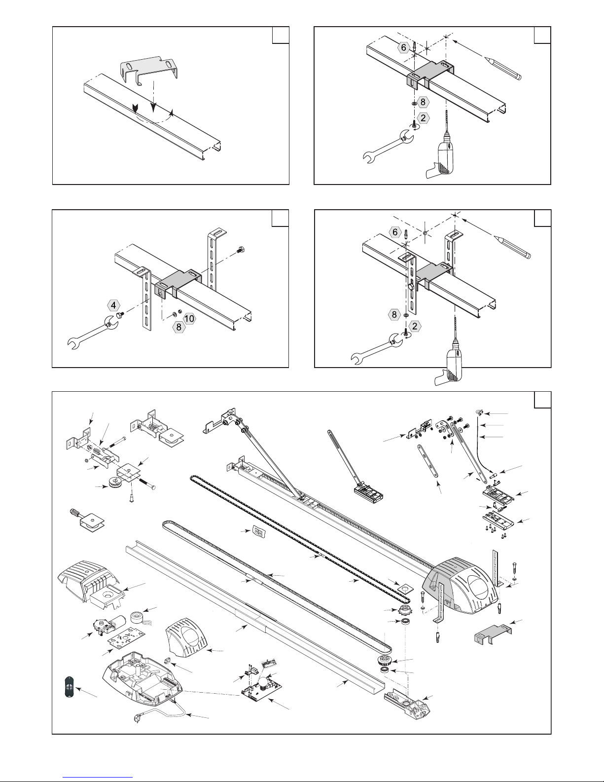
FIG. 33: Bring the centre suspension into place
• Place the centre suspension into the desired position from above on the rail and turn it in position.
FIG. 34: Fixing the centre suspension
• Mark the bore holes, drill the bore holes required and x the centre suspension on both sides using the dowels, screws and
washers specied.
FIG. 35: Suspend the centre suspension using slotted brackets
• Place the centre suspension into the desired position from above on the rail and turn it in position.
• Place the slotted brackets to obtain the desired projection and x the slotted brackets using the screws, nuts and washers
specied on both sides of the centre suspension.
FIG. 36: Fix the centre suspension to the slotted brackets
• Mark the bore holes, drill the bore holes required and x the centre suspension on both sides using the dowels, screws
and washers specied.
5.0 OPERATING THE SYSTEM
IMPORTANT SAFETY INSTRUCTIONS: ATTENTION – IT IS IMPORTANT FOR SAFEGUARDING HUMAN LIVES TO COMPLY WITH
ALL INSTRUCTIONS! THESE INSTRUCTIONS MUST BE KEPT IN SAFE CUSTODY!
When operating the emergency unlocking mechanism, there can be uncontrolled movements of the garage door
if springs are weak or broken or if the door is not balanced by weight. The emergency unlocking mechanism may
only be operated when the mains plug has been removed.
5.1 Instructions for safe operation
• Do not lean on the cord of the emergency unlocking mechanism with your body weight.
• Do not fasten any objects to the cord of the emergency unlocking mechanism or other components of the garage door
drive.
• Please ensure that the emergency unlocking mechanism or other moving parts of the system do not get caught on the
roof supporting structure or other projections of the motor vehicle or the garage door or any other objects in the garage.
• In the event of malfunctions or faults, the garage door can be opened / closed manually by operating the emergency
unlocking mechanism.
• Attention: The garage door can close faster if springs are weak, broken or defective and if the door weight is not balanced properly.
• Only operate the garage door when you can see the entire area covered by the door. Please ensure that there are no
human beings or objects in the path of movement of the garage door. Observe the moving door and keep persons away
until the door has opened or closed completely and has stopped moving.
• Ensure that the garage door is completely open and has stopped moving before driving in and out of the garage.
• Do not keep the handheld transmitter in tight pant pockets or similar clothing. This can cause unintended operation.
Do not allow children to play with the drive. Keep the wireless handheld transmitter away from children.
Please do not operate the garage door system if any repair or service work needs to be done, since a fault in
the system or an incorrectly adjusted garage door can lead to severe injuries. Please ensure that such work is
only carried out by qualied and skilled technicians.
Please do not operate the garage door system if any repair or service work needs to be done, since a fault in the
system or an incorrectly adjusted garage door can lead to severe injuries. Please ensure that such work is only
carried out by qualied and skilled technicians.
DOCOMATIC 19/23 04-10
Page 20
5.2 Operation
The garage door can be opened or closed in a number of ways using the garage door drive: using the handheld transmitter,
the START button or indoor button / key switch / wireless code lock (accessory). Each operation of an operating element
triggers a new impulse ("Impulse follow-up function"): Start - Stop - Reverse - etc.“). If the automatic door closing feature
is enabled (see 3.5 / b: binary add-on function / POINT 3) the drive door closes automatically after the door open time set
(see 3.5 / A: door open time) has elapsed. Following a power supply failure, any interrupted movement will not be resumed
when the power supply is restored.
In addition, every time that the drive is started, the internal and external lighting connected, if any, (see 4.8) is switched on
for the duration set for the lighting (see 3.5 / L: illumination period).
With regard to the operation of any signals or warning lamps that are connected, please take note of the information given
in 4.5 and/or 4.6.
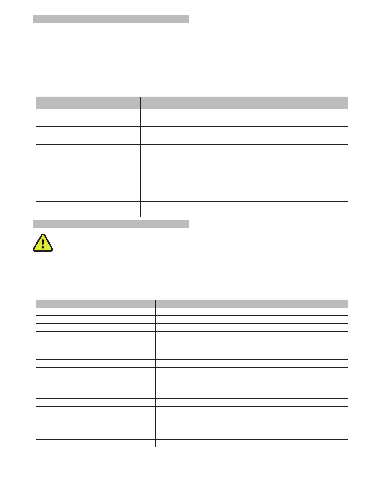
EVENT
when automatic door closing feature is enabled,
leads to:
when automatic door closing feature is enabled,
leads to:
Operating impulse while opening No reaction; the door moves to the end position
"Door open", and the countdown to the door
open time begins
Stop; any other impulse leads to the door closing
Operating impulse while closing The door stops and moves back to the "Door
open" end position, and the countdown to the
door open time begins
Stop; any other impulse leads to the door opening
Operating impulse during the door open time
period
The door open time is reset to zero and the countdown recommences
Not possible
Trigger of light barrier / safety switch strip during
opening
No reaction of the light barrier / safety switch strip
Is disabled (inactive)
No reaction of the light barrier / safety switch strip
Is disabled (inactive)
Trigger of light barrier / safety switch strip during
closing
The door stops and moves back to the "Door
open" end position, and the countdown to the
door open time begins
Stop and partial or complete reversal (depending
on the setting in menu "b", option 1)
Hindrance shutdown while opening Stop and partial or complete reversal (depending
on the setting in menu "b", option 1)
Stop and partial or complete reversal (depending
on the setting in menu "b", option 1)
Hindrance shutdown while closing Stop and partial or complete reversal (depending
on the setting in menu "b", option 1)
Stop and partial or complete reversal (depending
on the setting in menu "b", option 1)
5.3 Fault indications
ATTENTION - DANGER TO LIFE! Faults in the 230 V part of the system may only be attended to by skilled electrical
technicians. Service and repair work may only be carried out by qualied and skilled technicians. Please do not
operate the system if service or repair work is required!
Every time that the 230 V AC mains power supply is switched on, the rst thing the control electronics will do is to perform a
self-test (red and green LED's light up for a few seconds). After the equipment has been commissioned, the red LED goes off,
and the green LED lights up permanently to indicate that the device is ready for operation.
If the drive stops working or no longer starts up, the green LED goes off and the red LED lights up permanently. In addition,
you can also distinguish between the following based on various symbols (icons) in the multi-segment display:
DISPLAY DESCRIPTION ACKNOWLEDGMENT ACTION
0 Over-voltage in the circuit Auto-reset* Restore stabilised voltage conditions (230 V AC +/-10%)
1 Light barrier defective Auto-Reset* Safety elements Release light barrier / safety switch strip
2 Light barrier defective Auto-Reset* Release stop elements; if required, check the jumper (4.8)
3 Light barrier defective Auto-Reset*
Check the light barrier / safety switch strip as well as cables and terminals; Service or replace
4 Path not programmed Taste ENTER then program the drive (3.2)
5 Motor fault Taste ENTER Check motor connection cable. If required, replace the motor
6 Sensor failure Taste ENTER Check the sensor cable / plug. If required, change the motor
7 Processor fault (controller) Manuelles Reset** If required, replace the controller
8 ROM error (controller) Manuelles Reset** If required, replace the controller
9 RAM error (controller) Manuelles Reset** If required, replace the controller
A EEPROM error (controller) Manuelles Reset** If required, replace the controller
b Software error (controller) Manuelles Reset** If required, replace the controller
C Peripheral error (controller) Auto-Reset* Check all connections for proper working and correctness
H Hindrance / power-operated shutdown Auto-Reset*
Check the door movement manually; if required, repair the door; remove the hindrance
L Overload Auto-Reset*
The drive is overloaded by the door; Check the door movement manually; if required, have the door serviced or repaired
U Under-voltage in the circuit Auto-Reset* Restore stabilised voltage conditions (230 V AC +/-10%)
* Auto-reset: the fault indication goes off automatically as soon as normal operating conditions have been restored.
** Manual reset: Unplug the drive from the mains, wait for 10 sec. and switch it on again. If this does not reset the fault indi
cation, the corresponding component must be replaced.
DOCOMATIC 20/23 04-10
Page 21
5.4 Fault rectication
ATTENTION - DANGER TO LIFE! Faults in the 230 V part of the system may only be attended to by skilled electrical
technicians. Service and repair work may only be carried out by qualied and skilled technicians. Please do not
operate the system if service or repair work is required!
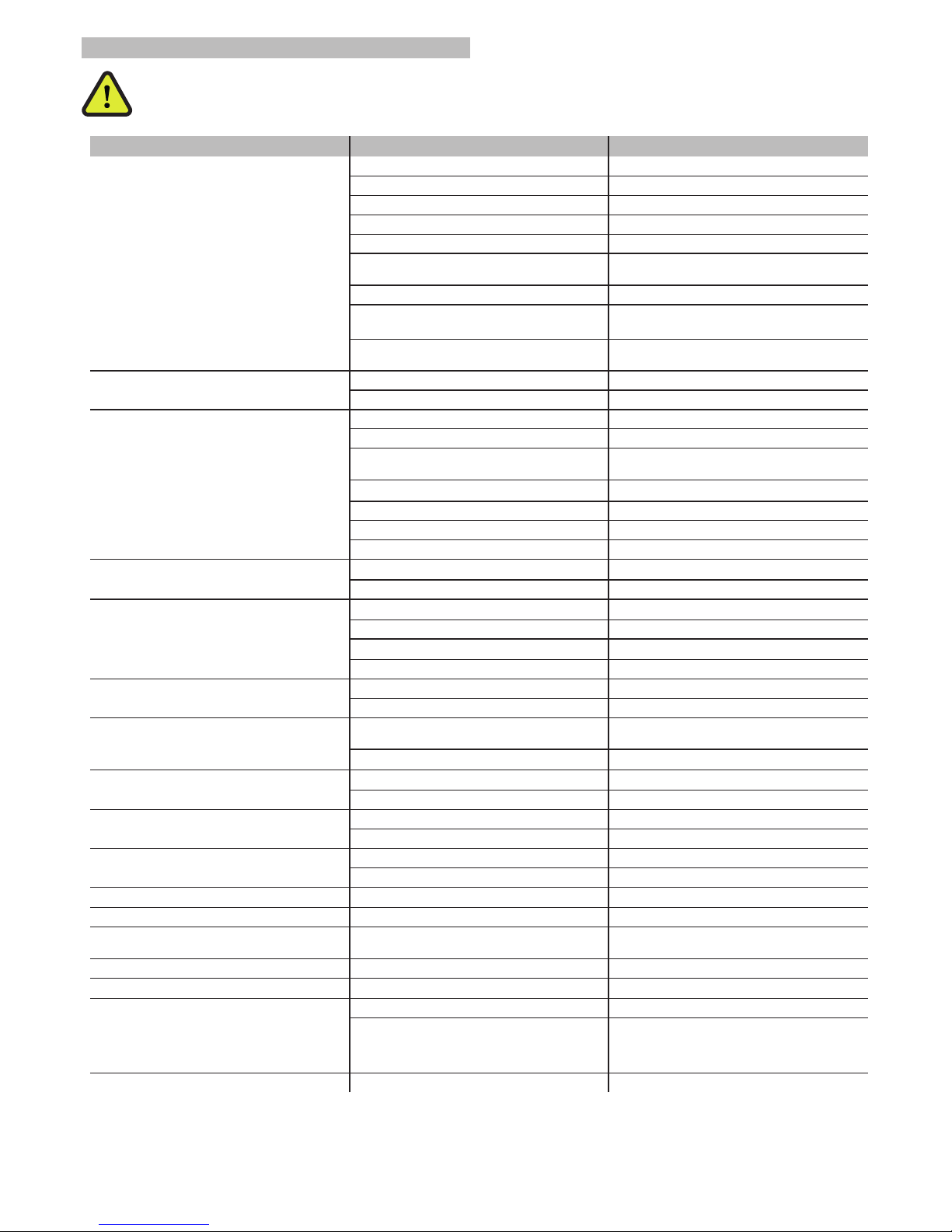
PROBLEM DEFINITION POSSIBLE CAUSE FAULT RECTIFICATION
No operation
FAULT RECTIFICATION Check the mains supply and upstream fuses
Internal ne fuses defective Check the fuses F1/F2
Transformer defective Check the transformer and replace it
Control board is defective Check the control board (5.3) and replace it
Motor is faulty Replace the motor
Safety features in menu (b4 / b5) enabled (activated), but not or incorrectly connected
Disable (deactivate) / check the connections
Safety device enabled (active) Check the safety device
Safety device enabled (active) Check it, and repair it
Jumper for emergency stop (see 4.8) is missing /
loose
Tighten the terminals / insert the jumper
No operation via the START terminals (1/2)
Button or operating element defective Replace button or operating element
Cable / connections defective Check / replace loose cables / connections
No function with wireless
Transmitter not trained Train transmitter
Interference while training Repeat the learning procedure
Transmitter battery discharged or inserted incorrectly
Check the battery
Transmitter defective Replace the transmitter
Receiver not plugged in properly Check if plug connection is live
Receiver defective Replace the receiver
Missing or improper antenna Have maintenance carried out on the door
Door opens slightly and switches off
Change in the door mechanics Have maintenance carried out on the door
(without any new installation) Correct the force setting
Door opens slightly and switches off
(after / with a new installation)
Force setting too low Correct the force setting
Door is too heavy Use a drive with higher power rating
Push rod angle too large Correct the installation
Door is very stiff Have maintenance carried out on the door
Door closes slightly and switches off / reverses
Change in the door mechanics Have maintenance carried out on the door
Hindrance in the path of movement Remove the hindrance
Door doesn’t stop / reverse for any hindrance
Door in learning movement
Repeat learning movement without hindrance.
Finally, check it again under normal operation
Controller defective Shut down operation, replace the controller
No operation despite motor noises
Gear defective / worn out Replace the motor
Drive pinion defective / worn out Replace the drive pinion
Toothed belt squeaks / chain clatters
Toothed belt / chain not properly tensioned Tighten it, and put a chain silencer in place
Toothed belt greased / lubricated Degrease and clean it completely
Water in the drive
Condensation in the garage Provide ventilation
Roof was drilled during installation Seal the roof
Door rubs on the drive rail Drive installed too low Shift the drive upwards
Door closes on its own Automatic door closing is enabled (active) Disable (deactivate) automatic door closing
Door opens / closes on its own Uncontrolled operation
Check the function / access to the operating
elements
Door moves after time delay Lead time enabled (activated) Set lead time to 0 sec.
Door only moves softly / slowly; Hall sensor cable loose / defective Check cable / connector
Motor / sensor is missing as per the indication
Hall sensor or cable is loose / defective; if required, replace the motor / cable
Gear defective Replace the motor
Light barrier / safety switch strip not working Feature not enabled (activated) in the menu Enable (activate) it (b4, b5)
DOCOMATIC 21/23 04-10
Page 22
5.5 Maintenance and repair
Please do not operate the garage door system if any repair or service work needs to be done, since a fault in the
system or an incorrectly adjusted garage door can lead to severe injuries.
Please have all repair and service work carried out by qualied and skilled technicians only. Only original spare
parts may be used for repair work.
• Please note that in the event of broken springs / cables, there is the potential hazard of the garage door falling down
when operating the emergency unlocking system.
• Never put your hand in the way of moving parts of the system while doing maintenance work. Keep a safe distance away
from moving parts (hazard of getting pulled in)!
• With except for programming work, the mains plug must always be pulled out before commencing any work on the garage door or the drive.
• We recommend that you get the entire system checked up by qualied technicians on an annual basis.
• The complete system, particularly fastenings, cables and springs as well as the drive chain and toothed belt, must be checked frequently for signs of wear and tear or damage, as well as for imbalance, strength or tension.
• The hindrance detection system (power-operated shutdown, see 3.4), and, if required, the safety elements connected
and the emergency unlocking mechanism (2.5) should be checked every 4 weeks. Any faults must be attended to immediately by a qualied and skilled technician.
• (FIG. 29) The following parts of the drive are subject to wear and tear and must be replaced after 80,000 operating cycles
or 10 years at the latest: Toothed belt (04.00-04.03), chain (05.00-05.02), deection roller assembly (07.00-07.04), drive assembly (6.00-06.04) and geared motor (01.02).
• Chains should be lubricated slightly once a year using a suitable lubricant. Toothed belts may not be lubricated under
any circumstances.
• If the appliance gets dirty, it must be cleaned in dry conditions, and, if required, using a vacuum cleaner. Under no circumstances may you use use water, steam or pressure cleaning.
6.0 DISMANTLING AND DISPOSAL
When dismantling and disposing of the equipment, please take note of and comply with the local rules and regulations on
safety and disposal.
7.0 TECHNICAL SPECIFICATIONS
120 (1200N)
Weight in kg ca. 19
Max. pulling / pushing force in N 1000
Max. speed in cm/sec 14
Max. running distance in m (3.00 m rail) ca. 2,40 (Sektionaltor jew. 2,25)
Max. door surface in m² 16,8
Minimum installation height in mm 35
Length in m (3.00 m rail) 3,29
Noise emission pressure level in dB(A) <= 70
Ambient temperature in °C -20 bis +40
Atmospheric humidity RH during operation in % 20-80 (jew. nicht kondens.)
Duty cycle 30% ED S3
Rated operating cycles in no. 80.000
Mains power supply 230V/AC (jew. 50-60Hz)
Rated motor power in W, max. 180
Protection class IP20
Consumption in W during standby ca. 4,5
Integrated lighting 230V AC 40W E14
DOCOMATIC 22/23 04-10
Page 23

8.0 ACCESSORIES
Wireless handheld transmitter 4-channel
Wireless handheld transmitter III 4-channel
Spare battery for handheld transmitter (CR 2032)
Wireless code lock 4-channel
Supplementary antenna with 6.00 m coaxial cable
Aluminium key switch IP54
Roof pull-button
Cord for roof pull-button
"FT" light barrier, 10 m range
Flap door contact
Safety switch strip 8.2 Kohm
Warning lamp 24 V, 15 W
Flash lamp 230 V, 15 W
Signal module
Green signal
Red signal
Rail extension 1.00 m
Rail extension 2.00 m
Rail extension 3.00 m
Push rod extender Various lengths on request
Supplementary locking set for the sectional door
Supplementary locking set for the hinged door
Sectional door tting
Swing door tting
Curved door arm (light-weight design)
Curved door arm (heavy-weight design)
Insert lock for emergency unlocking
DOCOMATIC 23/23 04-10
 Loading...