

Page 1
Blade™ & Blade Duo™
Installation Instructions
BLADE PART #:
0290-30000
0290-30001
0290-30002
Time Required - 30 min
Tools Needed:
• Jigsaw
• Drill
• Measuring Tape
BLADE DUO PART #:
0290-30100
0290-30101
0290-30400
0290-30102
0290-30402
• Screwdriver
• Square
• Pencil
• Cutout Template
CAUTION – READ CAREFULLY
• Failure to follow these instructions
can cause death or permanent injury.
Do not work on live electrical circuits!
Make absolutely certain power is o
before connecting the device!
• This product is for dry, indoor and
permanent installations only.
• Install the device in accordance with all
national and local electrical codes.
How to Install the Outlet
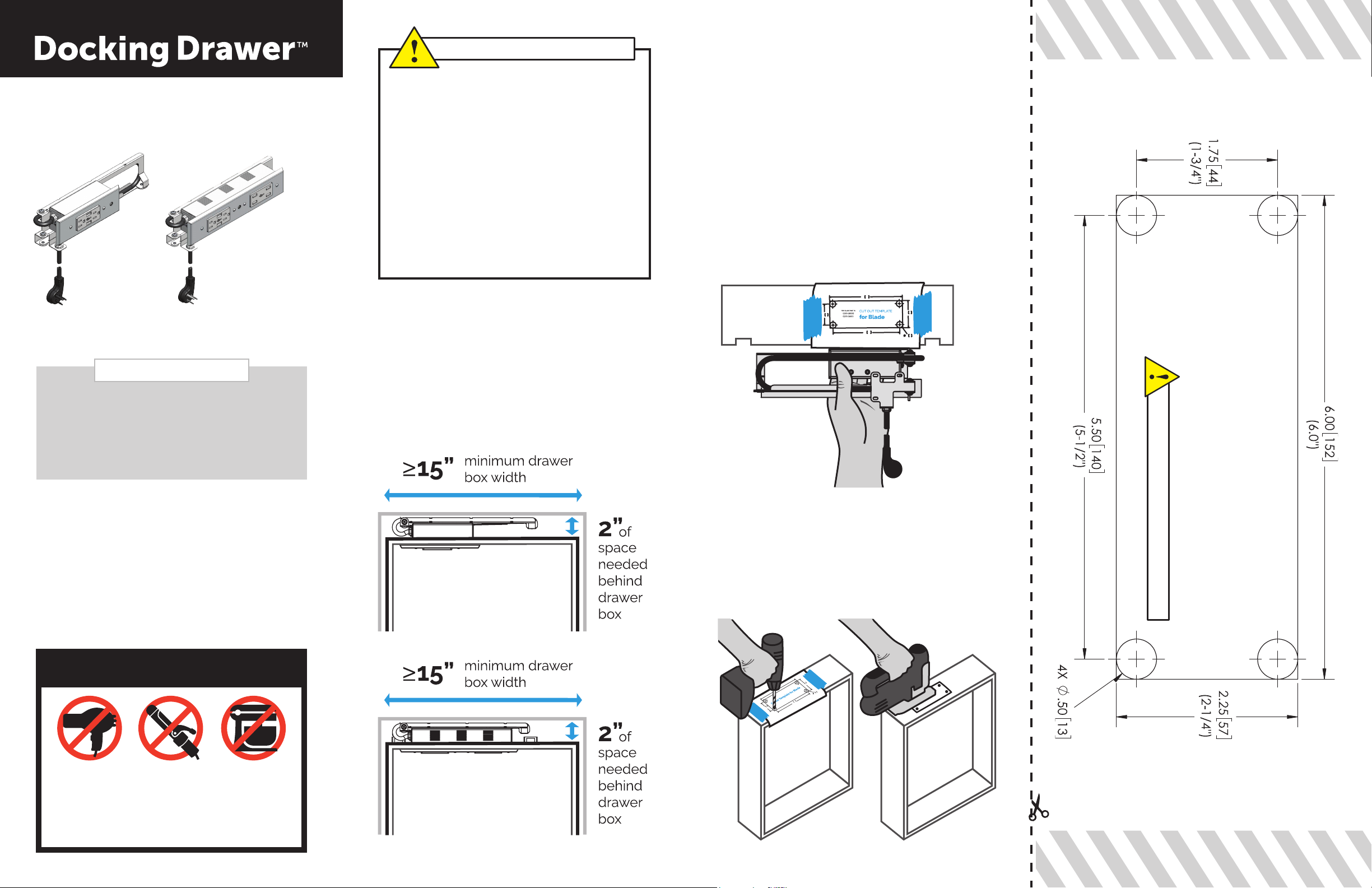
Step 1 - Verify the drawer dimensions.
Docking Drawer Blade and Blade Duo require
at least 2” behind the drawer box and at least a
15” wide drawer box.
Step 2 - Remove the cutout template and
ip to the side that corresponds with your
product’s part number.
Step 3 - Locate the proper location for
the receptacle box cutout using our cutout
template. You can locate the proper location
from either the inside or backside of the
drawer box, making sure that the arms will
not interfere with the slides and that there is
enough material surrounding the receptacle
box to securely hold it in place.
FOR ACCURACY SCALE PRINTER TO 100%
BLADE PART #:
0290-30000
0290-30001
0290-30002
for Blade
CUTOUT TEMPLATE
Visit our Specication Library at
www.dockingdrawer.com to nd:
Detailed Mounting Diagrams to plan your
installation, DXF and STEP Files for importing
into 2D and 3D layout programs, and our
Electrical Planning Guide to plan in-cabinet
power source for Docking Drawer outlets.
WARNING
This in-drawer outlet is intended for charging
technology only. This outlet WILL NOT power
a hair dryer, curling iron, mixer or other types
of high-powered devices.
DOCKING DRAWER
BLADE
DOCKING DRAWER
BLADE DUO
Step 4 - With a 1/2” drill bit, drill a hole in
each corner, being careful not to splinter the
wood on the inside of the drawer box. Using
one of the 1/2” holes, insert a jigsaw and then
make the required cutouts in the drawer box.
Page 2
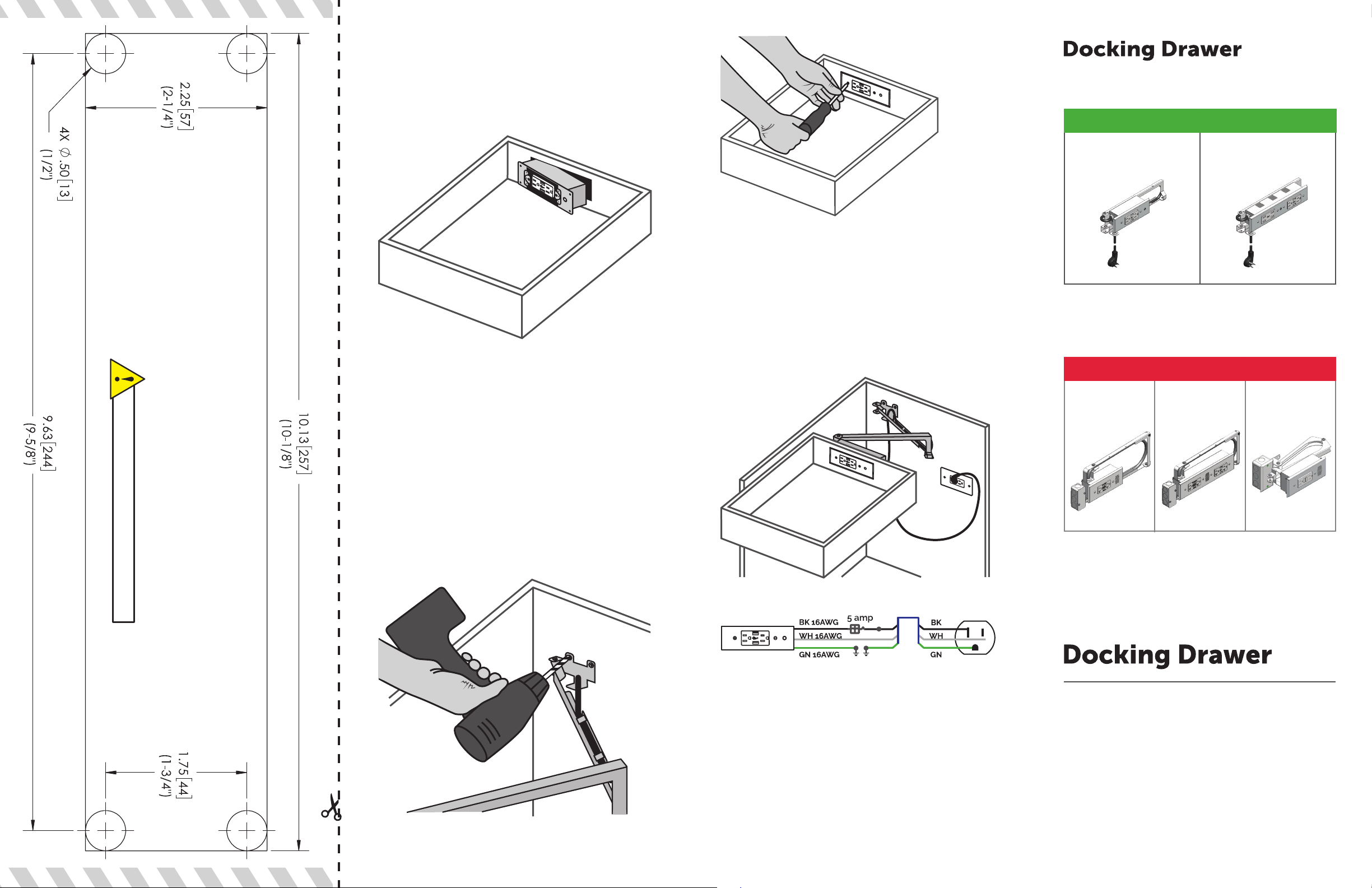
Step 5 - Reinstall the drawer box and slide
the Docking Drawer Blade or Blade Duo
receptacle box through the cutout. Secure it
with the 4 wood screws provided.
Step 7 - Install the
cover plate.
TM
Complete Outlet Lineup
CHARGING
0290-30400
0290-30102
0290-30402
for Blade Duo
FOR ACCURACY SCALE PRINTER TO 100%
BLADE DUO PART #:
0290-30100
0290-30101
CUTOUT TEMPLATE
Step 6 - Align arms. With the drawer mostly
closed, mark the position of the rear mounting
bracket. It is important to make sure the
drawer moves freely in and out and that the
arms are square and even. Spend sucient
time at this step before fastening the bracket
to the rear wall to make sure everything
is square and the arms are in the correct
position. Once that is done, secure with the
screws provided.
Step 8 - Connect the Docking Drawer power
cord to the in-cabinet electrical supply. For
more details about locating an in-cabinet
electrical supply for your Docking Drawer
installation, please refer to the Electrical
Planning Guide located in the Specication
Library at www.dockingdrawer.com.
Docking Drawer
Blade™
Max output: 3 amps. Perfect for charging cell
phones, tablets, and laptops.
POWERING
Style Drawer
Blade™
Max output: 20 amps, GFCI outlets. Perfect for
powering hair dryers, curling irons, and small
kitchen appliances.
Style Drawer
Blade Duo™
Docking Drawer
Blade Duo™
Style Drawer
Flush™
KMG040919
How to Operate the Outlet
Docking Drawer Blade and Blade Duo include a
resettable circuit breaker that prevents highpowered devices from being used. The circuit
breaker trip is indicated by the white button
protruding approximately 3/8” out from the
cover plate. To reset, correct the source of
overcurrent and push the white button in.
TM
Have questions? Need help? Call us!
(530) 205-3625
12893 Alcosta Blvd, Suite M,
San Ramon, CA 94583
www.dockingdrawer.com
 Loading...